EP3797004B1 - Systeme und verfahren für kombinierte bestrahlungs- und funktionsschichtanwendung - Google Patents
Systeme und verfahren für kombinierte bestrahlungs- und funktionsschichtanwendung Download PDFInfo
- Publication number
- EP3797004B1 EP3797004B1 EP20731834.6A EP20731834A EP3797004B1 EP 3797004 B1 EP3797004 B1 EP 3797004B1 EP 20731834 A EP20731834 A EP 20731834A EP 3797004 B1 EP3797004 B1 EP 3797004B1
- Authority
- EP
- European Patent Office
- Prior art keywords
- oxygen
- blocking layer
- unit
- printing plate
- layer application
- Prior art date
- Legal status (The legal status is an assumption and is not a legal conclusion. Google has not performed a legal analysis and makes no representation as to the accuracy of the status listed.)
- Active
Links
Images



Classifications
-
- G—PHYSICS
- G03—PHOTOGRAPHY; CINEMATOGRAPHY; ANALOGOUS TECHNIQUES USING WAVES OTHER THAN OPTICAL WAVES; ELECTROGRAPHY; HOLOGRAPHY
- G03F—PHOTOMECHANICAL PRODUCTION OF TEXTURED OR PATTERNED SURFACES, e.g. FOR PRINTING, FOR PROCESSING OF SEMICONDUCTOR DEVICES; MATERIALS THEREFOR; ORIGINALS THEREFOR; APPARATUS SPECIALLY ADAPTED THEREFOR
- G03F7/00—Photomechanical, e.g. photolithographic, production of textured or patterned surfaces, e.g. printing surfaces; Materials therefor, e.g. comprising photoresists; Apparatus specially adapted therefor
- G03F7/004—Photosensitive materials
- G03F7/09—Photosensitive materials characterised by structural details, e.g. supports, auxiliary layers
- G03F7/092—Photosensitive materials characterised by structural details, e.g. supports, auxiliary layers characterised by backside coating or layers, by lubricating-slip layers or means, by oxygen barrier layers or by stripping-release layers or means
-
- B—PERFORMING OPERATIONS; TRANSPORTING
- B05—SPRAYING OR ATOMISING IN GENERAL; APPLYING FLUENT MATERIALS TO SURFACES, IN GENERAL
- B05C—APPARATUS FOR APPLYING FLUENT MATERIALS TO SURFACES, IN GENERAL
- B05C9/00—Apparatus or plant for applying liquid or other fluent material to surfaces by means not covered by any preceding group, or in which the means of applying the liquid or other fluent material is not important
- B05C9/08—Apparatus or plant for applying liquid or other fluent material to surfaces by means not covered by any preceding group, or in which the means of applying the liquid or other fluent material is not important for applying liquid or other fluent material and performing an auxiliary operation
- B05C9/12—Apparatus or plant for applying liquid or other fluent material to surfaces by means not covered by any preceding group, or in which the means of applying the liquid or other fluent material is not important for applying liquid or other fluent material and performing an auxiliary operation the auxiliary operation being performed after the application
-
- B—PERFORMING OPERATIONS; TRANSPORTING
- B05—SPRAYING OR ATOMISING IN GENERAL; APPLYING FLUENT MATERIALS TO SURFACES, IN GENERAL
- B05D—PROCESSES FOR APPLYING FLUENT MATERIALS TO SURFACES, IN GENERAL
- B05D1/00—Processes for applying liquids or other fluent materials
- B05D1/02—Processes for applying liquids or other fluent materials performed by spraying
-
- B—PERFORMING OPERATIONS; TRANSPORTING
- B05—SPRAYING OR ATOMISING IN GENERAL; APPLYING FLUENT MATERIALS TO SURFACES, IN GENERAL
- B05D—PROCESSES FOR APPLYING FLUENT MATERIALS TO SURFACES, IN GENERAL
- B05D3/00—Pretreatment of surfaces to which liquids or other fluent materials are to be applied; After-treatment of applied coatings, e.g. intermediate treating of an applied coating preparatory to subsequent applications of liquids or other fluent materials
- B05D3/06—Pretreatment of surfaces to which liquids or other fluent materials are to be applied; After-treatment of applied coatings, e.g. intermediate treating of an applied coating preparatory to subsequent applications of liquids or other fluent materials by exposure to radiation
-
- B—PERFORMING OPERATIONS; TRANSPORTING
- B32—LAYERED PRODUCTS
- B32B—LAYERED PRODUCTS, i.e. PRODUCTS BUILT-UP OF STRATA OF FLAT OR NON-FLAT, e.g. CELLULAR OR HONEYCOMB, FORM
- B32B37/00—Methods or apparatus for laminating, e.g. by curing or by ultrasonic bonding
- B32B37/0046—Methods or apparatus for laminating, e.g. by curing or by ultrasonic bonding characterised by constructional aspects of the apparatus
- B32B37/0053—Constructional details of laminating machines comprising rollers; Constructional features of the rollers
-
- B—PERFORMING OPERATIONS; TRANSPORTING
- B32—LAYERED PRODUCTS
- B32B—LAYERED PRODUCTS, i.e. PRODUCTS BUILT-UP OF STRATA OF FLAT OR NON-FLAT, e.g. CELLULAR OR HONEYCOMB, FORM
- B32B38/00—Ancillary operations in connection with laminating processes
- B32B38/0004—Cutting, tearing or severing, e.g. bursting; Cutter details
-
- B—PERFORMING OPERATIONS; TRANSPORTING
- B32—LAYERED PRODUCTS
- B32B—LAYERED PRODUCTS, i.e. PRODUCTS BUILT-UP OF STRATA OF FLAT OR NON-FLAT, e.g. CELLULAR OR HONEYCOMB, FORM
- B32B38/00—Ancillary operations in connection with laminating processes
- B32B38/0008—Electrical discharge treatment, e.g. corona, plasma treatment; wave energy or particle radiation
-
- B—PERFORMING OPERATIONS; TRANSPORTING
- B32—LAYERED PRODUCTS
- B32B—LAYERED PRODUCTS, i.e. PRODUCTS BUILT-UP OF STRATA OF FLAT OR NON-FLAT, e.g. CELLULAR OR HONEYCOMB, FORM
- B32B38/00—Ancillary operations in connection with laminating processes
- B32B38/18—Handling of layers or the laminate
- B32B38/1808—Handling of layers or the laminate characterised by the laying up of the layers
- B32B38/1816—Cross feeding of one or more of the layers
-
- G—PHYSICS
- G03—PHOTOGRAPHY; CINEMATOGRAPHY; ANALOGOUS TECHNIQUES USING WAVES OTHER THAN OPTICAL WAVES; ELECTROGRAPHY; HOLOGRAPHY
- G03F—PHOTOMECHANICAL PRODUCTION OF TEXTURED OR PATTERNED SURFACES, e.g. FOR PRINTING, FOR PROCESSING OF SEMICONDUCTOR DEVICES; MATERIALS THEREFOR; ORIGINALS THEREFOR; APPARATUS SPECIALLY ADAPTED THEREFOR
- G03F7/00—Photomechanical, e.g. photolithographic, production of textured or patterned surfaces, e.g. printing surfaces; Materials therefor, e.g. comprising photoresists; Apparatus specially adapted therefor
- G03F7/16—Coating processes; Apparatus therefor
-
- G—PHYSICS
- G03—PHOTOGRAPHY; CINEMATOGRAPHY; ANALOGOUS TECHNIQUES USING WAVES OTHER THAN OPTICAL WAVES; ELECTROGRAPHY; HOLOGRAPHY
- G03F—PHOTOMECHANICAL PRODUCTION OF TEXTURED OR PATTERNED SURFACES, e.g. FOR PRINTING, FOR PROCESSING OF SEMICONDUCTOR DEVICES; MATERIALS THEREFOR; ORIGINALS THEREFOR; APPARATUS SPECIALLY ADAPTED THEREFOR
- G03F7/00—Photomechanical, e.g. photolithographic, production of textured or patterned surfaces, e.g. printing surfaces; Materials therefor, e.g. comprising photoresists; Apparatus specially adapted therefor
- G03F7/16—Coating processes; Apparatus therefor
- G03F7/161—Coating processes; Apparatus therefor using a previously coated surface, e.g. by stamping or by transfer lamination
-
- G—PHYSICS
- G03—PHOTOGRAPHY; CINEMATOGRAPHY; ANALOGOUS TECHNIQUES USING WAVES OTHER THAN OPTICAL WAVES; ELECTROGRAPHY; HOLOGRAPHY
- G03F—PHOTOMECHANICAL PRODUCTION OF TEXTURED OR PATTERNED SURFACES, e.g. FOR PRINTING, FOR PROCESSING OF SEMICONDUCTOR DEVICES; MATERIALS THEREFOR; ORIGINALS THEREFOR; APPARATUS SPECIALLY ADAPTED THEREFOR
- G03F7/00—Photomechanical, e.g. photolithographic, production of textured or patterned surfaces, e.g. printing surfaces; Materials therefor, e.g. comprising photoresists; Apparatus specially adapted therefor
- G03F7/20—Exposure; Apparatus therefor
- G03F7/2002—Exposure; Apparatus therefor with visible light or UV light, through an original having an opaque pattern on a transparent support, e.g. film printing, projection printing; by reflection of visible or UV light from an original such as a printed image
- G03F7/201—Exposure; Apparatus therefor with visible light or UV light, through an original having an opaque pattern on a transparent support, e.g. film printing, projection printing; by reflection of visible or UV light from an original such as a printed image characterised by an oblique exposure; characterised by the use of plural sources; characterised by the rotation of the optical device; characterised by a relative movement of the optical device, the light source, the sensitive system or the mask
-
- G—PHYSICS
- G03—PHOTOGRAPHY; CINEMATOGRAPHY; ANALOGOUS TECHNIQUES USING WAVES OTHER THAN OPTICAL WAVES; ELECTROGRAPHY; HOLOGRAPHY
- G03F—PHOTOMECHANICAL PRODUCTION OF TEXTURED OR PATTERNED SURFACES, e.g. FOR PRINTING, FOR PROCESSING OF SEMICONDUCTOR DEVICES; MATERIALS THEREFOR; ORIGINALS THEREFOR; APPARATUS SPECIALLY ADAPTED THEREFOR
- G03F7/00—Photomechanical, e.g. photolithographic, production of textured or patterned surfaces, e.g. printing surfaces; Materials therefor, e.g. comprising photoresists; Apparatus specially adapted therefor
- G03F7/20—Exposure; Apparatus therefor
- G03F7/2002—Exposure; Apparatus therefor with visible light or UV light, through an original having an opaque pattern on a transparent support, e.g. film printing, projection printing; by reflection of visible or UV light from an original such as a printed image
- G03F7/2014—Contact or film exposure of light sensitive plates such as lithographic plates or circuit boards, e.g. in a vacuum frame
- G03F7/2016—Contact mask being integral part of the photosensitive element and subject to destructive removal during post-exposure processing
- G03F7/202—Masking pattern being obtained by thermal means, e.g. laser ablation
-
- G—PHYSICS
- G03—PHOTOGRAPHY; CINEMATOGRAPHY; ANALOGOUS TECHNIQUES USING WAVES OTHER THAN OPTICAL WAVES; ELECTROGRAPHY; HOLOGRAPHY
- G03F—PHOTOMECHANICAL PRODUCTION OF TEXTURED OR PATTERNED SURFACES, e.g. FOR PRINTING, FOR PROCESSING OF SEMICONDUCTOR DEVICES; MATERIALS THEREFOR; ORIGINALS THEREFOR; APPARATUS SPECIALLY ADAPTED THEREFOR
- G03F7/00—Photomechanical, e.g. photolithographic, production of textured or patterned surfaces, e.g. printing surfaces; Materials therefor, e.g. comprising photoresists; Apparatus specially adapted therefor
- G03F7/20—Exposure; Apparatus therefor
- G03F7/2035—Exposure; Apparatus therefor simultaneous coating and exposure; using a belt mask, e.g. endless
-
- B—PERFORMING OPERATIONS; TRANSPORTING
- B05—SPRAYING OR ATOMISING IN GENERAL; APPLYING FLUENT MATERIALS TO SURFACES, IN GENERAL
- B05C—APPARATUS FOR APPLYING FLUENT MATERIALS TO SURFACES, IN GENERAL
- B05C9/00—Apparatus or plant for applying liquid or other fluent material to surfaces by means not covered by any preceding group, or in which the means of applying the liquid or other fluent material is not important
- B05C9/08—Apparatus or plant for applying liquid or other fluent material to surfaces by means not covered by any preceding group, or in which the means of applying the liquid or other fluent material is not important for applying liquid or other fluent material and performing an auxiliary operation
- B05C9/14—Apparatus or plant for applying liquid or other fluent material to surfaces by means not covered by any preceding group, or in which the means of applying the liquid or other fluent material is not important for applying liquid or other fluent material and performing an auxiliary operation the auxiliary operation involving heating or cooling
-
- B—PERFORMING OPERATIONS; TRANSPORTING
- B32—LAYERED PRODUCTS
- B32B—LAYERED PRODUCTS, i.e. PRODUCTS BUILT-UP OF STRATA OF FLAT OR NON-FLAT, e.g. CELLULAR OR HONEYCOMB, FORM
- B32B2310/00—Treatment by energy or chemical effects
- B32B2310/08—Treatment by energy or chemical effects by wave energy or particle radiation
- B32B2310/0806—Treatment by energy or chemical effects by wave energy or particle radiation using electromagnetic radiation
- B32B2310/0831—Treatment by energy or chemical effects by wave energy or particle radiation using electromagnetic radiation using UV radiation
-
- B—PERFORMING OPERATIONS; TRANSPORTING
- B32—LAYERED PRODUCTS
- B32B—LAYERED PRODUCTS, i.e. PRODUCTS BUILT-UP OF STRATA OF FLAT OR NON-FLAT, e.g. CELLULAR OR HONEYCOMB, FORM
- B32B2310/00—Treatment by energy or chemical effects
- B32B2310/08—Treatment by energy or chemical effects by wave energy or particle radiation
- B32B2310/0806—Treatment by energy or chemical effects by wave energy or particle radiation using electromagnetic radiation
- B32B2310/0837—Treatment by energy or chemical effects by wave energy or particle radiation using electromagnetic radiation using actinic light
Definitions
- LAMS Laser Ablative Mask System
- the LAMS layer is typically ablated in accordance with an image pattern, leaving gaps in the LAMS layer such that when actinic radiation, typically radiation in the ultraviolet (UV) spectrum, is applied to the plate, polymer in the gaps is exposed to the actinic radiation and cured.
- Later processing e.g. a washing step
- US 6 180 325 B1 describes a method for exposing photo-sensitive printing plates comprising applying a patterned coating to the printing plate to form a mask.
- the coating may be sprayed onto the printing plate and patterned by laser ablation.
- the printing plate is exposed to actinic radiation without dismounting it from the apparatus in which the coating is applied.
- EP 3 130 466 A2 describes an apparatus for preparing a screen for screen printing including a housing having a screen bed for placement of a pre-stretched, ultraviolet sensitive emulsion coated screen in a rectangular frame, the frame including a first end, a second end opposing the first end, a first side and a second side opposing the first side, a registration system attached to the screen bed for positioning the frame, wherein the registration system includes a first retainer for contacting a first end of the frame, a second retainer perpendicular to the first retainer for contacting a side of the frame perpendicular to the first end, and a biasing mechanism having a planar vertical plate for contacting a second end of the frame.
- US 5 228 920 A describes an apparatus for applying protective coatings to photographic films or papers in web or sheet form, wherein the protective coatings are curable by actinic radiation.
- the apparatus includes a feeding station for supplying film, which may be either a feed spool or a sheet feeder for holding and supplying individual sheets of film.
- the apparatus further includes a conveyor for conveying the film through a coating station and a curing chamber to a receiving station which also may either be a take-up spool to receive coated cured film or a stacking device to receive a stack of individual sheets of film.
- the conveyor can either be a series of conveying spools or pulleys or an endless conveyor belt in the case of individual sheets of film.
- the coating station includes a coating roller having a pattern of grooves formed by winding wire onto the surface thereof or other pattern of surface indentations.
- US 2013/209939 A1 describes a combined laminating and exposing apparatus for exposing a photosensitive printing blank to actinic radiation in a printing plate manufacturing system and a method of using the same.
- the photosensitive printing blank comprises a backing layer, at least one photocurable layer disposed on the backing layer, and a laser ablatable mask layer disposed on the at least one photocurable layer, wherein the laser ablatable mask layer is laser ablated to create an in situ negative in the laser ablatable mask layer.
- the exposing apparatus comprises: (a) a laminating apparatus for laminating an oxygen barrier layer to a top of the laser ablated mask layer; (b) a conveyor; (c) a first exposing device for imagewise exposing the at least one photocurable layer to actinic radiation, and (d) a second exposing device for exposing the at least one photocurable layer to actinic radiation through the backing layer.
- LED sources typically have such high intensities that flattop dots can be created even without the help of an oxygen-blocking barrier.
- using an oxygen-blocking layer in conjunction with LED exposure sources offers the advantage of reducing the irradiance required for plate exposure as compared to exposure without oxygen blocking layer.
- providing systems configured to apply an oxygen-blocking layer prior to an LED source exposure step may have certain advantages.
- the one or more radiation sources comprises an bank of UV LED sources arranged in a linear configuration perpendicular to the first direction
- the means for causing the one or more radiation sources and commonly located functional layer application unit to traverse relative to the target in the first direction comprises a movable carriage to which the one or more radiation sources and the functional layer application unit are mounted.
- the functional layer application unit may comprise a coating unit configured to apply the functional layer in a liquid form onto the target surface, such as in the form of a spray coating.
- the functional layer application unit comprises a lamination unit configured to apply the functional layer as a solid laminate.
- the lamination unit may comprise a laminate supply unit configured to feed the solid laminate over the target surface as the one or more radiation sources and commonly located lamination unit traverse relative to the target; and a pressure applicator, such as a roller, configured to apply the solid laminate to the target surface as the one or more radiation sources and commonly located lamination unit traverse relative to the target.
- the laminate supply unit may comprise a holder configured to hold a spool of laminate, having has an axis disposed perpendicular to the direction of travel, and pressure applicator roller also having an axis disposed perpendicular to the direction of travel.
- a cutter such as a blade configured to travel perpendicular to the direction of travel of the lamination unit during application of the laminate, is configured to cut the solid laminate adjacent the trailing edge of the target.
- a second roller which may have a different cross sectional diameter from the pressure applicator roller, may be disposed adjacent the pressure applicator roller and having an axis parallel to the pressure applicator roller axis, with the pressure applicator roller and second roller configured to receive the laminate therebetween during operation of the system.
- the pressure applicator roller axis is located ahead of the second roller axis in the direction of travel as the laminate is applied, and in a second configuration, the second roller axis is located ahead of the pressure applicator roller axis in the direction of travel.
- the pressure applicator roller and the second roller may be mounted to a rack that is rotatable between the first configuration and the second configuration.
- a laminate take-up unit which may have a fixed position relative to the functional layer application unit, may be configured to retrieve the solid laminate from the target surface after the one or more radiation sources and commonly located lamination unit traverse relative to the target.
- a second pressure applicator positioned between a trailing radiation source and the laminate take-up unit may be configured to keep the foil in contact with the mask upstream of the take-up unit.
- the functional layer application unit has variable position, and in some embodiments, a cutter is configured to cut the solid laminate adjacent the trailing edge of the target.
- the functional layer application unit may have a variable position, with a temporary stationary position located downstream of a trailing end of the plate. In this embodiment, the system is configured to secure the functional layer application unit in the temporary stationary position after a foil application pass, conduct one or more exposure passes after the foil application pass, and then retrieve the functional layer application unit following a final exposure pass.
- the method may comprise dispensing the coating as a liquid coating, such as by spraying the coating.
- the functional layer application unit comprises a lamination unit and the combined radiation / functional layer application unit comprises a pressure applicator, wherein the steps comprise feeding a solid laminate from the functional layer supply and applying pressure with the pressure applicator prior to exposing the printing plate.
- the laminate supply unit may comprise a holder configured to hold a spool of laminate and the pressure applicator may comprises a roller, wherein the method comprises unspooling the laminate from the functional layer supply unit and laminating the functional layer onto the printing plate using the roller.
- the method comprising disposing the laminate between the pressure applicator roller and the second roller, providing the relative motion between the combined radiation and lamination unit and the printing plate, positioning the pressure applicator roller and second roller in a first configuration in which the pressure applicator roller axis is located ahead of the second roller axis in the first direction for at least a first time period, then repositioning the pressure applicator roller and second roller in a second configuration in which the second roller axis is located ahead of the pressure applicator roller axis in the first direction for a second time period, and cutting the laminate adjacent a trailing edge of the plate during the second time period.
- the method comprises rotating the rack after the laminate is laminated to a trailing edge of the printing plate in the first direction.
- Some method embodiments may also comprise a step of retrieving the solid laminate from the target surface onto a take-up unit after the one or more radiation sources and commonly located lamination unit traverse relative to the target.
- the solid laminate may be wound and unwound between the functional layer supply and the take-up unit during each pass, and then rewinding the functional layer onto the functional layer supply from the take-up unit after the plurality of exposure steps.
- the solid laminate may be cut adjacent the trailing edge of the target after a first pass, the one or more radiation sources may then make multiple passes, and the solid laminate may be wound onto the take-up unit after a final pass.
- the combined radiation / functional layer application unit may be mounted to a movable carriage and the step of causing relative motion may comprise moving the carriage while the printing plate remains in a fixed position.
- Still another embodiment of the invention comprises a method for preparing a printing plate including providing a combined radiation / functional layer application unit with one or more radiation sources configured to emit radiation and a functional layer application unit commonly located with the one or more radiation sources, in which the functional layer application unit comprises a functional layer supply unit configured to hold a supply spool of an oxygen-blocking functional layer in the form of a solid laminate.
- the combined radiation / functional layer application unit comprises a pressure applicator and a cutter.
- the pressure applicator comprises laminate disposed between a first roller and a second roller.
- the functional layer is disposed over the printing plate surface from the functional layer supply unit during relative motion between the printing plate and the combined radiation / functional layer application unit.
- Laminate is unspooled from a functional layer supply unit and laminated onto the printing plate, and the printing plate is exposed through the functional layer to the radiation emitted from the one or more radiation sources.
- the laminate is cut adjacent a trailing edge of the printing plate with a cutter.
- the first and second rollers are disposed in a first configuration in which the first roller axis is located ahead of the second roller axis in the direction of travel for at least a first time period, then repositioned in a second configuration in which the second roller axis is located ahead of the first roller axis in the direction of travel for a second time period, during which the laminate is cut.
- the first and second rollers may be mounted to a rack rotatable between the first configuration and the second configuration, wherein the method comprises rotating the rack after the laminate is laminated to a trailing edge of the printing plate in the first direction.
- the method comprises rotating the rack after the laminate is laminated to a trailing edge of the printing plate in the first direction.
- Embodiments of the foregoing include embodiments in which the plate is stationary.
- Still another embodiment of the invention comprises a combined radiation and functional layer application system having one or more radiation sources and a functional layer application unit commonly located with the one or more radiation sources comprising a lamination unit configured to apply the functional layer as a solid laminate.
- the lamination unit comprises a laminate supply unit configured to feed the solid laminate over the target surface as the one or more radiation sources and commonly located lamination unit traverse relative to the target.
- the laminate supply unit comprises a holder configured to hold a spool of laminate with an axis of the spool of laminate disposed perpendicular to the first direction, and a pressure applicator configured to apply the solid laminate to the target surface as the one or more radiation sources and commonly located lamination unit traverse relative to the target.
- the pressure applicator comprises a first roller and a second roller, each roller having an axis disposed perpendicular to the first direction, the first and second rollers configured to receive the laminate therebetween during operation of the system and having a first configuration in which the first roller axis is located ahead of the second roller axis in the first direction, and a second configuration in which the second roller axis is located ahead of the first roller axis in the first direction.
- a cutter is configured to cut the solid laminate adjacent the trailing edge of the target.
- the one or more radiation sources and commonly located functional layer application unit are configured to move relative to the target in a first direction moving from the leading edge to the trailing edge, with the functional layer application unit positioned to apply the functional layer to the target ahead of the one or more radiation sources in the first direction.
- the first and second rollers may have different cross-sectional diameters, and may be mounted to a rack rotatable between the first configuration and the second configuration.
- the cutter preferably comprises at least one blade configured to travel in a direction perpendicular to the direction of relative travel between the plate and the combined radiation and functional layer application system.
- the plate is configured to remain stationary.
- a laminate take-up unit may be located in a fixed position relative to the functional layer application unit and configured to retrieve the solid laminate from the target surface after the one or more radiation sources and commonly located lamination unit traverse relative to the target.
- the fixed position of the laminate take-up unit may be adjacent an input of a washing unit.
- One or more radiation sources may be configured to emit radiation toward a back surface of the printing plate.
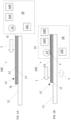
- one exemplary embodiment of the invention comprises a system 100 comprising one or more radiation sources 16A, 16B, 16C and a functional layer application unit 14 commonly located with the one or more radiation sources in a combination radiation / functional layer application unit 18.
- the functional layer supply unit 14 is configured to dispose the functional layer 15 over the surface of a target 12, such as a printing plate comprising a polymer layer 17 that is reactive to the actinic radiation and a mask 13, such as a LAMS layer, during relative motion between the target 12 and the combination radiation / functional layer application unit 18.
- a target 12 such as a printing plate comprising a polymer layer 17 that is reactive to the actinic radiation and a mask 13, such as a LAMS layer
- the term "functional layer” as used herein refers to any layer of material applied over a target, such as the printing plate, which has some function in the system.
- the functional layer is an oxygen barrier layer.
- Each radiation source 16A, 16B, 16C is configured to emit radiation, such as radiation in the UV spectrum, toward a surface of a target 12, such as a printing plate.
- the printing plate 12 may be fixed on substrate 11, while the combination radiation / functional layer application unit 18 traverses in the direction of arrow T.
- the plate can be characterized as having a leading edge LE (which is first to receive radiation) and a trailing edge TE (which is last to receive the radiation).
- Substrate 11 is preferably transparent to, or at least only partially blocks, the actinic radiation in at least an area that receives radiation from source 16C.
- substrate 11 may comprise glass, such as a glass plate with a UV transmission of around 80% or higher, such as is a known property for iron free glass.
- the functional layer application unit 14 is positioned to apply functional layer 15 to the plate 12 ahead of at least radiation sources 16A, 16B on the same side of the plate as the functional layer application unit.
- Radiation source 16C for providing back exposure may be aligned with a contact point C where the functional layer first contacts the plate, or it may be located upstream or downstream of that contact point in the direction of exposure motion.
- downstream means in the direction of arrow T
- upstream means in the direction opposite arrow T.
- each source as depicted may comprise an array of LED point sources, and that each array may comprise a plurality of rows of sources extending across a width of the plate perpendicular to the direction of travel, and that the number of rows in each source may be the same or different.
- Each array may comprise LED point sources having a single wavelength or a mixture of LED point sources of different species each having a different nominal center wavelength.
- functional layer 15 is present on the surface of the plate only downstream of the contact point C.
- the functional layer application unit 14 is configured to laminate a film onto the plate.
- the invention is not limited to such embodiments, however.
- functional layer application unit 14 may comprise a unit for disposing a liquid layer onto the plate such as via spray coating or a coating unit that uses a doctor blade for spreading liquid disposed on the plate by any means.
- the liquid coating may be any type of coating known in the art and curable by any method known in the art, or may comprise a liquid that does not require curing to be an effective oxygen blocker.
- the coating may be rapidly air curable such that it cures in the amount of time it takes for the combination unit 18 to move over a point on the plate the distance between application unit 14 and radiation unit 16A.
- radiation unit 16A may be a radiation unit configured to cure the coating prior to application of radiation from source 16B.
- the functional layer application unit comprises a lamination unit, which typically has three general components: a reservoir spool 21 for the oxygen blocking foil 25, a pressure roller 22 to press the foil against the polymer plate 24, and a cutter 23 to cut off the foil from the reservoir after lamination.
- a lamination unit typically has three general components: a reservoir spool 21 for the oxygen blocking foil 25, a pressure roller 22 to press the foil against the polymer plate 24, and a cutter 23 to cut off the foil from the reservoir after lamination.
- Spool-to-spool embodiments without a cutter are described herein later with reference to FIGS. 6A - 7B .
- Rollers 21 and 22 have axes arranged perpendicular to the direction of motion T of roller 22 relative to the plate 25 (which relative motion may comprise roller 22 moving over a fixed plate in the direction of arrow T, or plate 25 moving in a direction opposite arrow T relative to a fixed roller 22).
- Cutter 23 may move in direction C, which is also perpendicular to the direction of relative motion T.
- Cutter 23 may comprise any means for cutting known in the art, and the depiction in FIG. 2A is intended only to be schematic in nature.
- suitable cutters may include a pair of blades configured to shear the foil between the blades, a single blade with a sharp edge facing in direction C, a laser, a heated blade, a roller blade, or the like.
- Mechanisms for moving a cutter across a film to cut it are well known in the art and are not detailed here.
- pressure roller 42B may have a relatively larger cross sectional diameter than a relatively smaller roller 42A disposed adjacent to it.
- the axes of the rollers (a1 for roller 42A, and a2 for roller 42B) are disposed parallel to one another, and the rollers are configured to receive the laminate therebetween during operation of the system.
- Both rollers may be mounted on a rack 46 configured to be turned 180° along arrow R about axis A (parallel to axes a1 and a2) from a laminating configuration 40 as depicted in FIG. 3A , to a cutting configuration 48 as depicted in FIG. 3B .
- axis a1 of roller 42a is located ahead ("downstream") in the direction of arrow T of the axis a2 of roller 42b in the direction of travel of the lamination unit relative to the plate.
- roller axis a2 of roller 42B is located ahead (downstream) of the axis a1 of roller 42A in the direction of travel.
- the dual roller system lifts the foil up from the polymer plate in the cutting configuration to provide easier access for cutting with the cutting tool. This type of system provides better control of the loose end of the oxygen blocking foil during the lamination process as compared to a single roller system. As noted in FIG.
- the roller may be configured to run at a first height relative to the surface of the plate 24, as depicted in FIG. 2A , and then dip to a second, relatively lower height as depicted in FIG. 2B , in order to complete a cutting step.
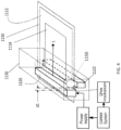
- the combination unit 18 as depicted in FIG. 1A may be embodied in the form of a carriage 1130 in the configuration shown in FIG. 4 .
- Carriage 1130 may comprise a back side linear source 1122 arranged to irradiate the back side of a plate 1114 mounted on transparent surface 1112, such as a glass plate.
- a top side linear source 1120 (which although depicted schematically as a single source, may comprise two or more sources, as depicted in FIG. 1A ) is arranged to irradiate the top side of the plate.
- the functional layer application unit 1150 is positioned downstream (in the direction of arrow L) of the top side linear source(s).
- Each linear source, and the functional layer application unit 1150 extends to cover one dimension of the plate, which in the example shown shall be referred to as the transverse direction.
- the carriage traverses the plate in the longitudinal (or lateral) direction along arrow L in at least a first pass, with at least one source, and preferably both sources, activated. While the exposure step may be performed in a single pass, in some embodiments the exposure may be performed in a plurality of passes, in which each pass imparts radiation using both banks of sources at a fraction of the total exposure needed to provide a desired amount of exposure.
- the carriage may have a first speed when traversing the plate along the direction of arrow L with radiation sources activated, and a second, faster speed when traversing the plate in the direction opposite arrow L, to reset for another pass or at the completion of the desired number of passes.
- the overall mechanism for creating the exposure may comprise a table having an outer frame 1110 that holds a transparent (e.g. glass) inner portion 1112.
- the upper 1120 and lower 1122 linear radiation sources e.g. banks of LED point sources, optionally mounted inside a reflective housing
- the trailing edge of light source 1122 and leading edge of light source 1120 are separated by a distance (d1) to provide a desired amount of time delay between back and front exposure.
- the radiation sources are connected to a power source, such as an electrical power cord having sufficient slack to extend the full range of motion of the carriage.
- Tracks (not shown) disposed on the outer frame portion provide a defined path for the gantry system or carriage to traverse.
- the carriage may be moved on the tracks by any drive mechanism known in the art (also coupled to the power supply and the controller), including a chain drive, a spindle drive, gear drive, or the like.
- the drive mechanism for the carriage may comprise one or more components mounted within the carriage, one or more components fixed to the table, or a combination thereof.
- a position sensor (not shown) is preferably coupled to the carriage to provide feedback to the controller regarding the precise location of the carriage at any given time.
- the control signal output from the controller for operating the radiation sources and for controlling motion of the carriage may be supplied via a wired or wireless connection.
- the controller may be mounted in a fixed location, such as connected to the table with a control signal cable attached to the sources similar to the power cable, or may be mounted in or on the carriage.
- the control system and drive mechanism cooperate to cause back/forth relative motion in a transverse direction between the light from the radiation sources and the plate.
- the drive mechanism is configured to move the portion of the table containing the plate past stationary upper and lower linear radiation sources, as well as embodiments in which the radiation sources cover less than the full width of the plate and are movable in both the transverse and longitudinal direction to provide total plate coverage (or the plate is movable in both directions, or the plate is movable in one of the two directions and the sources are movable in the other direction to provides the full range of motion required to cover the entire plate).
- the control system in addition to controlling the drive mechanism and the radiation sources, may also control the cutter and the functional layer application unit as described herein.
- Sensors (not shown specifically, but generally encompassed as part of the control system) mounted in the carriage may detect when the relevant portion of the layer application unit is disposed over the trailing edge of the plate and may thus cause the functional layer application unit to transition from a lamination configuration to a cutting configuration, such as in the manner as described herein, and then cause the cutter to cut the film.
- the control system may control the flow of liquid to the liquid application system for supplying oxygen-blocking liquid to the plate.
- FIG. 5 depicts schematically a side view of a combined radiation and functional layer application system liquid coating example useful for the understanding of the disclosure.
- the combination radiation / functional layer application unit comprises functional layer application unit 60 commonly located with the radiation sources 54, 56, 58.
- Plate 68 is disposed on a conveyor system comprising conveyor belt 66 and conveyor belt 84, which move the plate along the direction of arrow T past a fixed radiation / functional layer application unit.
- Plate 68 preferably has a LAMS layer (not shown) on a top surface thereof.
- Functional layer application unit 60 comprises a liquid applicator, such as a spray bar configured to spray an oxygen-blocking fluid in a layer 70 on the upper surface of the plate.
- application unit 60 may dispose a stream (rather than a spray) of liquid on the plate and member 72 may be a doctor blade set a predetermined distance above the plate to spread the applied liquid in an even layer.
- member 72 may be configured to cure the applied oxygen blocking liquid by applying heat, air, actinic radiation at a wavelength that cures the oxygen blocking liquid but not the plate polymer, etc.
- Conveyor 66 may be in the form of a grid or may have numerous perforations so that any excess liquid (such as pushed off the trailing edge of the plate) may pass through the conveyor into a disposal unit 64.
- Back exposure unit 58 is located upstream (opposite the direction of arrow T) of the functional layer application unit 60 in a gap between conveyor belts 84 and 66.
- Conveyor belt 66 is driven by drums 50 and 52 (one of which may be active, and the other of which may be passive, or both may be active), and conveyor belt 84 is likewise driven by drums 80 and 82.
- Controller 62 controls the speed of the conveyor 66 by controlling speed of the drums (although depicted as controlling only drum 50, it may control both drums 50 and 52, or only drum 52 instead), controls radiation exposure by controlling sources 52, 56, and 58 (which may be configured for variable intensities), and controls liquid application unit 60. Sensors configured to detect the trailing edge of plate 68 may be used for controlling when to apply the liquid. Power to the controller, the radiation sources, and the conveyor may be supplied by a power source (not shown).
- the liquid dispensed by application unit 60 may be supplied by a pump (not shown) or gravity flow from a reservoir (not shown) and may be controlled by one or more valves (not shown) that may be binary (on/off) and/or variable (to control flow within a range, which range may be dictated by the speed of the conveyor, depth of liquid desired, effectiveness of the liquid, and the like).
- a single conveyor may be used with the back exposure aligned with or located downstream of the functional layer application point.
- the conveyor 66 may also be desirable for the conveyor 66 to be transparent or suitably translucent to the back exposure radiation. It may be desirable in any liquid application based system to provide a cleaning station 90 for the conveyor belt in some portion of the belt travel after the plate is discharged from drum 50 and before a new plate is received on drum 52, to remove any overspray or otherwise undesired liquid present on the conveyor.
- FIGS. 6A and 6B are similar to the system depicted in FIGS. 1A and 1B , except that in system 600, the functional layer 15 extends between the functional layer application unit 614 positioned ahead of radiation sources 616A, 616B and a functional layer take-up unit 619 positioned after the radiation sources (when traversing in the T direction).
- the system may continuously unwind the functional layer from spool 621, press it onto the plate with roller 622, and rewind it onto take-up spool 620.
- Optional pressure roller 623 may be positioned just ahead of take-up spool 620 to ensure that the functional layer does not lift off too early.
- spool 621 may unwind and spool 620 may wind when making a pass in the direction of arrow T, and spool 621 may wind and spool 620 may unwind the functional layer when making a pass in the opposite direction (in the-T direction).
- An optional back exposure radiation source 616C may also be present.
- the radiation sources and functional layer application and take-up units may all be included together in a moving combination unit 616. Because the foil is not cut, the foil may be used for several exposure steps on several different plates, in which case the foil may be rewound onto spool 621 from spool 620 after the completion of a first exposure step or series of exposure steps, before commencing the next exposure step or series of exposure steps.
- the spool may hold enough foil to handle multiple exposure steps (on multiple plates) before rewinding.
- system 700 comprises stationary take-up unit 719, comprising take-up spool 720 and roller 723, may be stationary behind the start positon of the moving combination unit 718, or example at the input of a washing unit 730.
- Moving combination unit contains sources 716A, 716B, and 716C and the foil application unit 714, comprising foil reservoir spool 721, pressure roller 742a, and adjacent roller 742b (with rollers 742a and 742b having functionality similar to 42a and 42b, as described herein with respect to FIGS. 3A and 3B ).
- the foil may be cut, to permit subsequent passes in the T and -T directions, without further disturbing the foil.
- Stationary take-up unit 719 may then be used to peel off and store away the used foil from the plate after a multitude of exposure steps, before the plate is moved into the washing unit 730.
- foil application unit 814 may comprise only foil reservoir spool 821 and pressure roller 842.
- foil 15 is not cut at the end of the first pass, but instead, as depicted in FIG. 8B , the foil application unit 814 is dropped off at a stationary location at the end of the first pass in a location downstream of the trailing edge of the plate.
- the foil remains stationary on both ends of the plate through a plurality of exposure step passes in the T and -T direction, and then the roller is picked up again on the last pass in the T direction, and the foil is then removed from the plate during the final pass in the -T direction.
- the system secures the functional layer application unit in the temporary stationary position after a foil application pass, conducts one or more exposure passes after the foil application pass, and then retrieves the functional layer application unit following a final exposure pass. After the exposure step for a first plate, the foil may then be used again for the exposure steps of one or more additional plates.
- the foil may be wound spool-to-spool between reservoir spool 821 and take-up spool 720 to position "fresh" foil for use in a subsequent exposure.
- spool 821 is referred to as a reservoir spool and spool 720 as a "take-up" spool in this and various other embodiments, it should be understood that the functions of the spools may be reversed with respect to which roll supplies the "fresh foil.” While it may be more convenient for spool 821 to have fresh foil and spool 720 to have used foil, a system may be implemented such that spool 821 takes a predetermined amount of fresh foil needed from spool 720 in a foil winding step so that it can cover the full expanse of the plate with fresh foil for a subsequent set of exposure steps.
- rollers 22, 42a/42b, 622, 623, 742a/742b, 723, 842 may be configured to be raised or lowered up and down (perpendicular to arrow T) as needed to permit the plate to pass underneath the respective units when moving from the exposure step to a washing step in a workflow.
- the distance between the back exposure radiation source (e.g. 58, 16C) and the front exposure radiation sources (e.g. 54 / 56, 16A /16B) in combination with the speed of travel of the plate (in the example depicted in FIG. 5 ) or of the carriage (in the system depicted in FIGS. 1A and 1B may be set (and may be adjustable) to provide a desired delay time between the back exposure and the front exposure steps.
- the distance between the back exposure radiation source (e.g. 58, 16C) and the front exposure radiation sources (e.g. 54 / 56, 16A /16B) in combination with the speed of travel of the plate (in the example depicted in FIG. 5 ) or of the carriage (in the system depicted in FIGS. 1A and 1B may be set (and may be adjustable) to provide a desired delay time between the back exposure and the front exposure steps.
Landscapes
- Physics & Mathematics (AREA)
- General Physics & Mathematics (AREA)
- Engineering & Computer Science (AREA)
- Plasma & Fusion (AREA)
- Thermal Sciences (AREA)
- Architecture (AREA)
- Structural Engineering (AREA)
- Optics & Photonics (AREA)
- Manufacture Or Reproduction Of Printing Formes (AREA)
- Application Of Or Painting With Fluid Materials (AREA)
- Exposure And Positioning Against Photoresist Photosensitive Materials (AREA)
- Manufacturing & Machinery (AREA)
Claims (15)
- Ein kombiniertes Bestrahlungs- und Sauerstoffsperrschicht-Anwendungssystem, das Folgendes umfasst:eine oder mehrere LED-UV-Strahlungsquellen (16A, 16B), wobei die eine oder mehreren Strahlungsquellen (16A, 16B) konfiguriert sind, um Strahlung in Richtung einer oberen Oberfläche einer Druckplatte (12) mit einer LAMS-Schicht zu emittieren, wobei die Druckplatte (12) eine Vorderkante (LE) und eine Hinterkante (TE) aufweist;eine Sauerstoffsperrschicht-Anwendungseinheit (14), die mit der einen oder den mehreren Strahlungsquellen (16A, 16B) angeordnet ist, wobei die Sauerstoffsperrschicht-Anwendungseinheit (14) konfiguriert ist, um eine Sauerstoffsperrschicht (15) über der Oberfläche der LAMS-Schicht anzuordnen;Mittel zum Bewirken einer relativen Bewegung zwischen der Druckplatte (12) und den Strahlungsquellen (16A, 16B) und der Sauerstoffsperrschicht-Anwendungseinheit (14) in einer ersten Richtung, die bewirken, dass die Sauerstoffsperrschicht (15) von der Vorderkante (LE) zur Hinterkante (TE) aufgebracht wird, wobei die Sauerstoffsperrschicht-Anwendungseinheit (14) so positioniert ist, dass sie die Sauerstoffsperrschicht (15) auf die Druckplatte (12) vor (ahead of) der einen oder den mehreren Strahlungsquellen (16A, 16B) in der ersten Richtung aufbringt,wobei die Mittel zum Bewirken einer Relativbewegung bewirken, dass sich die eine oder mehreren Strahlungsquellen (16A, 16B) und die Sauerstoffsperrschicht-Anwendungseinheit (14) bewegen und die Druckplatte (12) stationär ist.
- Das kombinierte Bestrahlungs- und Sauerstoffsperrschicht-Anwendungssystem nach Anspruch 1, wobei die Sauerstoffsperrschicht-Anwendungseinheit (14) eine Beschichtungseinheit umfasst, die konfiguriert ist, um die Sauerstoffsperrschicht (15) in flüssiger Form auf die Druckplattenoberfläche aufzutragen, und, optional
wobei die Beschichtungseinheit konfiguriert ist, um die Beschichtung als Sprühbeschichtung aufzutragen. - Das kombinierte Bestrahlungs- und Sauerstoffsperrschicht-Anwendungssystem nach Anspruch 1, wobei die Sauerstoffsperrschicht-Anwendungseinheit (14) eine Laminiereinheit umfasst, die konfiguriert ist, um die Sauerstoffsperrschicht (15) als ein festes Laminat aufzutragen, wobei die Laminiereinheit Folgendes umfasst:eine Laminat-Versorgungseinheit, die konfiguriert ist, um das feste Laminat über die Druckplattenoberfläche zuzuführen, während sich die eine oder mehrere Strahlungsquellen (16A, 16B) und die Laminiereinheit relativ zur Druckplatte (12) bewegen; undeinen Druckapplikator, der konfiguriert ist, um das feste Laminat auf die Druckplattenoberfläche aufzubringen, während sich die eine oder die mehreren Strahlungsquellen (16A, 16B) und die Laminiereinheit relativ zur Druckplatte (12) bewegen.
- Das kombinierte Bestrahlungs- und Sauerstoffsperrschicht-Anwendungssystem nach Anspruch 3, das ferner eine Schneidvorrichtung (23) umfasst, die konfiguriert ist, um das feste Laminat angrenzend an die Hinterkante (TE) der Druckplatte (12) zu schneiden.
- Das kombinierte Bestrahlungs- und Sauerstoffsperrschicht-Anwendungssystem nach Anspruch 3, wobei der Druckapplikator eine Druckapplikatorwalze umfasst, wobei die Druckapplikatorwalze eine Achse aufweist, die senkrecht zur ersten Richtung angeordnet ist, wobei das System eine zweite Walze umfasst, die an die Druckapplikatorwalze angrenzt und eine Achse aufweist, die parallel zur Druckapplikatorwalzen-Achse verläuft, wobei die Druckapplikatorwalze und die zweite Walze so konfiguriert sind, dass sie das Laminat während des Betriebs des Systems dazwischenliegend aufnehmen, und eine erste Konfiguration aufweisen, in der die Druckapplikatorwalzen-Achse in der ersten Richtung vor der Achse der zweiten Walze angeordnet ist, und eine zweite Konfiguration aufweisen, in der die Achse der zweiten Walze in der ersten Richtung vor der Druckapplikatorwalzen-Achse angeordnet ist, und, optional,
wobei die Druckapplikatorwalze und die zweite Walze an einem Gestell (46) angebracht sind, und wobei das Gestell (46) zwischen der ersten Konfiguration und der zweiten Konfiguration drehbar ist. - Das kombinierte Bestrahlungs- und Sauerstoffsperrschicht-Anwendungssystem nach Anspruch 3, ferner umfassend eine Laminat-Aufnahmeeinheit (619, 719), die konfiguriert ist, um das feste Laminat von der Druckplattenoberfläche zurückzuholen (retrieve), nachdem sich die eine oder mehreren Strahlungsquellen (16A, 16B) und die Laminiereinheit relativ zur Druckplatte (12) bewegt haben, und, optional,
ferner umfassend einen zweiten Druckapplikator, der zwischen einer nachlaufenden Strahlungsquelle und der Laminat-Aufnahmeeinheit (619, 719) angeordnet ist, um die Folie in Kontakt mit der Maske stromaufwärts der Aufnahmeeinheit (619, 719) zu halten. - Das kombinierte Bestrahlungs- und Sauerstoffsperrschicht-Anwendungssystem nach irgendeinem der vorhergehenden Ansprüche,wobei die eine oder mehreren Strahlungsquellen (16A, 16B) eine Bank von UV-LED-Quellen umfassen, die in einer linearen Konfiguration senkrecht zur ersten Richtung angeordnet sind; und/oderwobei die Mittel zum Bewirken der Bewegung von einer oder mehreren Strahlungsquellen (16A, 16B) und der Sauerstoffsperrschicht-Anwendungseinheit (14) relativ zur Druckplatte (12) in der ersten Richtung einen beweglichen Schlitten (1130) umfassen, an dem die eine oder mehreren Strahlungsquellen (16A, 16B) und die Sauerstoffsperrschicht-Anwendungseinheit (14) montiert sind; und/oderferner umfassend eine oder mehrere Strahlungsquellen (16C), die konfiguriert sind, um Strahlung in Richtung einer hinteren Oberfläche der Druckplatte (12) zu emittieren.
- Ein Verfahren zum Vorbereiten bzw. Herstellen (preparing) einer Druckplatte (12), wobei das Verfahren Folgendes umfasst:(a) Bereitstellen eines kombinierten Bestrahlungs- und Sauerstoffsperrschicht-Anwendungssystems nach irgendeinem der Ansprüche von 1 bis 7;(b) Fixieren der Druckplatte (12) relativ zur Sauerstoffsperrschicht-Anwendungseinheit (14) und einer oder mehreren Strahlungsquellen (16A, 16B), wobei eine Oberfläche der Druckplatte (12) ausgerichtet wird, um Strahlung von der einen oder den mehreren Strahlungsquellen (16A, 16B) und die Sauerstoffsperrschicht (15) von der Sauerstoffsperrschicht-Anwendungseinheit (14) zu empfangen;(c) Bewirken, dass sich die eine oder mehreren Strahlungsquellen (16A, 16B) und die Sauerstoffsperrschicht-Anwendungseinheit (14) in der ersten Richtung relativ zur stationären Druckplatte (12) bewegen, während die Sauerstoffsperrschicht (15) von der Sauerstoffsperrschicht-Anwendungseinheit (14) über die Druckplattenoberfläche aufgebracht wird, und anschließendes Belichten der Druckplatte (12) durch die Sauerstoffsperrschicht (15) mit der von der einen oder den mehreren Strahlungsquellen (16A, 16B) emittierten Strahlung.
- Das Verfahren nach Anspruch 8, wobei die Sauerstoffsperrschicht eine Beschichtung umfasst, und der Schritt des Anwendens der Sauerstoffsperrschicht (15) auf die Druckplattenoberfläche das Aufbringen der Beschichtung als flüssige Beschichtung umfasst, und, optional
wobei der Schritt des Anwendens der Sauerstoffsperrschicht (15) das Aufsprühen der Beschichtung umfasst. - Das Verfahren nach Anspruch 8, wobei die Sauerstoffsperrschicht (15) ein festes Laminat umfasst, wobei die Sauerstoffsperrschicht-Anwendungseinheit (14) eine Laminiereinheit umfasst, und wobei die Sauerstoffsperrschicht-Anwendungseinheit (14) ferner einen Druckapplikator umfasst,
wobei die Schritte Folgendes umfassen: Zuführen des festen Laminats von der Sauerstoffsperrschicht-Versorgungseinheit, und Aufbringen von Druck mit dem Druckapplikator in Schritt (c) vor dem Belichten der Druckplatte (12). - Das Verfahren nach Anspruch 10, das ferner Folgendes umfasst: Zurückholen des festen Laminats von der Druckplattenoberfläche auf eine Aufnahmeeinheit (619, 719), nachdem sich die eine oder mehrere Strahlungsquellen (16A, 16B) und die Laminiereinheit relativ zur Druckplatte (12) bewegt haben.
- Das Verfahren nach Anspruch 11, das Folgendes umfasst: Durchführen mehrerer Durchgänge mit der einen oder den mehreren Strahlungsquellen (16A, 16B), und Auf- und Abwickeln des festen Laminats zwischen der Sauerstoffsperrschicht-Versorgungseinheit und der Aufnahmeeinheit (619, 719) während jedes Durchgangs.
- Das Verfahren nach Anspruch 12, das Folgendes umfasst: Durchführen einer Vielzahl von Belichtungsschritten mit der einen oder den mehreren Strahlungsquellen (16A, 16B), und Aufwickeln der Sauerstoffsperrschicht (15) auf die Sauerstoffsperrschicht-Versorgungseinheit von der Aufnahmeeinheit (619, 719) nach der Vielzahl von Belichtungsschritten.
- Das Verfahren nach Anspruch 13, wobei die Laminat-Aufnahmeeinheit (619, 719) eine feste Position hat und die Sauerstoffsperrschicht-Anwendungseinheit (14) eine variable Position hat, ferner umfassend: Schneiden des festen Laminats angrenzend an die Hinterkante (TE) der Druckplatte (12) nach einem ersten Durchgang, Durchführen mehrerer Durchgänge mit der einen oder den mehreren Strahlungsquellen (16A, 16B), und Aufwickeln des festen Laminats auf die Aufnahmeeinheit (619, 719) nach einem letzten Durchgang.
- Das Verfahren nach Anspruch 13, wobei die Sauerstoffsperrschicht-Anwendungseinheit (14) eine variable Position hat und eine temporäre stationäre Position aufweist, wobei die temporäre stationäre Position stromabwärts eines hinteren Endes der Druckplatte (12) angeordnet ist, wobei das Verfahren Folgendes umfasst: Auftragen der Sauerstoffsperrschicht (15) in einem ersten Durchgang, Sichern der Sauerstoffsperrschicht-Anwendungseinheit (14) in der temporären stationären Position nach dem ersten Durchgang, Durchführen eines oder mehrerer Belichtungsdurchgänge nach dem ersten Durchgang, und dann Zurückholen der Sauerstoffsperrschicht-Anwendungseinheit (14) nach einem letzten Belichtungsdurchgang.
Applications Claiming Priority (2)
| Application Number | Priority Date | Filing Date | Title |
|---|---|---|---|
| US201962857456P | 2019-06-05 | 2019-06-05 | |
| PCT/EP2020/065676 WO2020245393A1 (en) | 2019-06-05 | 2020-06-05 | Systems and methods for combined radiation and functional layer application |
Publications (2)
| Publication Number | Publication Date |
|---|---|
| EP3797004A1 EP3797004A1 (de) | 2021-03-31 |
| EP3797004B1 true EP3797004B1 (de) | 2024-05-08 |
Family
ID=71078509
Family Applications (1)
| Application Number | Title | Priority Date | Filing Date |
|---|---|---|---|
| EP20731834.6A Active EP3797004B1 (de) | 2019-06-05 | 2020-06-05 | Systeme und verfahren für kombinierte bestrahlungs- und funktionsschichtanwendung |
Country Status (4)
| Country | Link |
|---|---|
| US (1) | US12023706B2 (de) |
| EP (1) | EP3797004B1 (de) |
| CN (1) | CN112673318B (de) |
| WO (1) | WO2020245393A1 (de) |
Families Citing this family (1)
| Publication number | Priority date | Publication date | Assignee | Title |
|---|---|---|---|---|
| CN115852307A (zh) * | 2022-12-07 | 2023-03-28 | 重庆金美新材料科技有限公司 | 一种高分子基膜表面处理方法、设备及镀膜产品 |
Family Cites Families (24)
| Publication number | Priority date | Publication date | Assignee | Title |
|---|---|---|---|---|
| US5228920A (en) * | 1991-06-03 | 1993-07-20 | Thompson Iii Ernest E | Film coating unit |
| US5262275A (en) | 1992-08-07 | 1993-11-16 | E. I. Du Pont De Nemours And Company | Flexographic printing element having an IR ablatable layer and process for making a flexographic printing plate |
| US6180325B1 (en) * | 1999-06-23 | 2001-01-30 | Creo Srl | Method for masking and exposing photosensitive printing plates |
| JP2004338304A (ja) * | 2003-05-16 | 2004-12-02 | Fuji Photo Film Co Ltd | 湿し水不要平版印刷版原版の製造方法 |
| JP4684685B2 (ja) | 2005-03-03 | 2011-05-18 | 富士フイルム株式会社 | 感光性平版印刷版及びその製造方法 |
| US8389203B2 (en) | 2007-05-08 | 2013-03-05 | Esko-Graphics Imaging Gmbh | Exposing printing plates using light emitting diodes |
| US7807001B2 (en) * | 2007-06-28 | 2010-10-05 | Eastman Kodak Company | Lamination device method for flexographic plate manufacturing |
| US8227769B2 (en) | 2008-05-27 | 2012-07-24 | Esko-Graphics Imaging Gmbh | Curing of photo-curable printing plates with flat tops or round tops |
| US8492074B2 (en) | 2011-01-05 | 2013-07-23 | Laurie A. Bryant | Method of improving print performance in flexographic printing plates |
| US8772740B2 (en) | 2011-04-08 | 2014-07-08 | Esko-Graphics Imaging Gmbh | UV curing creating flattop and roundtop structures on a single printing plate |
| US8551688B2 (en) | 2011-04-21 | 2013-10-08 | Ryan W. Vest | Photosensitive resin laminate and thermal processing of the same |
| US8669041B2 (en) | 2011-07-15 | 2014-03-11 | Brian Cook | Method for improving print performance of flexographic printing elements |
| US8871431B2 (en) | 2011-08-08 | 2014-10-28 | Timothy Gotsick | Laminated flexographic printing sleeves and methods of making the same |
| JP5401522B2 (ja) | 2011-09-15 | 2014-01-29 | 富士フイルム株式会社 | コーティング組成物、ならびに該組成物を用いた、画像形成材料、平版印刷版原版及び酸素遮断性フィルム |
| US8697337B2 (en) | 2012-01-23 | 2014-04-15 | Albert G. Roshelli, JR. | Laminating apparatus and method of using the same |
| US8524442B1 (en) * | 2012-02-13 | 2013-09-03 | David A. Recchia | Integrated membrane lamination and UV exposure system and method of the same |
| US9649837B2 (en) | 2013-03-15 | 2017-05-16 | M&R Printing Equipment, Inc. | Method and apparatus for preparing a screen printing screen |
| CA2923703C (en) | 2013-09-18 | 2021-10-05 | Flint Group Germany Gmbh | Digitally exposable flexographic printing element and method for producing flexographic printing plates |
| EP3054352B1 (de) | 2015-02-06 | 2017-11-08 | Flint Group Germany GmbH | Automatisierte uv-led belichtung von flexodruckplatten |
| ES2781325T3 (es) | 2015-05-28 | 2020-09-01 | Flint Group Germany Gmbh | Placa de impresión flexográfica capaz de ser ilustrada digitalmente con capa de barrera integral |
| JP6768217B2 (ja) | 2015-09-28 | 2020-10-14 | 東洋紡株式会社 | 感光性凸版印刷原版 |
| US10732507B2 (en) | 2015-10-26 | 2020-08-04 | Esko-Graphics Imaging Gmbh | Process and apparatus for controlled exposure of flexographic printing plates and adjusting the floor thereof |
| EP3368949B1 (de) * | 2015-10-26 | 2022-02-16 | Esko-Graphics Imaging GmbH | System und verfahren zur gesteuerten belichtung von flexodruckplatten |
| US9925757B2 (en) | 2016-02-10 | 2018-03-27 | Macdermid Graphics Solutions, Llc | Customizable printing plates and method of making the same |
-
2020
- 2020-06-05 EP EP20731834.6A patent/EP3797004B1/de active Active
- 2020-06-05 US US16/972,293 patent/US12023706B2/en active Active
- 2020-06-05 CN CN202080003673.6A patent/CN112673318B/zh active Active
- 2020-06-05 WO PCT/EP2020/065676 patent/WO2020245393A1/en not_active Ceased
Also Published As
| Publication number | Publication date |
|---|---|
| CN112673318B (zh) | 2024-05-24 |
| WO2020245393A1 (en) | 2020-12-10 |
| CN112673318A (zh) | 2021-04-16 |
| US20220184652A1 (en) | 2022-06-16 |
| US12023706B2 (en) | 2024-07-02 |
| EP3797004A1 (de) | 2021-03-31 |
Similar Documents
| Publication | Publication Date | Title |
|---|---|---|
| US4087182A (en) | Process and apparatus for producing a photopolymer plate having relief images thereon | |
| JP2018535830A5 (de) | ||
| EP2269911B1 (de) | Vorrichtung zum Anbringen von Etikettenstreifen an Behältnissen | |
| EP3121653B1 (de) | Vorrichtung und verfahren zur photopolymerisation von digitalen flexographischen druckplatten | |
| DE102008028949B4 (de) | Oberflächenbehandlungsvorrichtung für ein bedrucktes Blatt | |
| KR102156200B1 (ko) | 양면 코팅장치 | |
| WO2006129870A2 (en) | Method of and apparatus for partly cutting laminated film | |
| US12023706B2 (en) | Systems and methods for combined radiation and functional layer application | |
| JP3376935B2 (ja) | 帯状ワークの露光装置 | |
| US20170066614A1 (en) | Method and apparatus for manufacturing a tape | |
| US5865118A (en) | Method and apparatus for punching and imaging a continuous web | |
| WO2023008456A1 (ja) | 転写装置 | |
| US5826513A (en) | Method and apparatus for punching and imaging a continuous web | |
| EP3545360B1 (de) | Belichtungsvorrichtung und verfahren zur belichtung von plattenförmigen materialien | |
| RU2000132246A (ru) | Способ и устройство для изготовления комбинированного материала, состоящего по меньшей мере из одной полимерной пленки, несущей информацию, и по меньшей мере одной подложки и предназначенного для дальнейшей обработки при изготовлении защищенных от подделки документов | |
| KR20080050425A (ko) | 적층체의 박리 장치 및 박리 방법 | |
| KR20190086884A (ko) | 패턴 성형 장치 | |
| KR102676614B1 (ko) | Ppf 코팅 시스템 및 그 방법 | |
| US20260115758A1 (en) | Sheet embellishing system and non-transitory storage medium storing machine-readable program | |
| CN117836148B (zh) | 用于柔性版印刷元件的热处理的方法和系统 | |
| JP7764774B2 (ja) | 貼付装置、液体吐出装置、電極形成装置、多層セパレータ形成装置および貼付方法 | |
| US20060084005A1 (en) | Means to enable slitting of micro-encapsulated media | |
| JP2000347396A (ja) | 所望幅の感光性ドライフィルムレジスト原反ロールの作製装置、および所望幅の感光性ドライフィルムレジスト原反ロールの作製方法 | |
| HK40103659A (zh) | 用於柔性版印刷元件的热处理的方法和系统 | |
| EP1154326A1 (de) | Verfahren und Vorrichtung zur Herstellung von Druckplatten |
Legal Events
| Date | Code | Title | Description |
|---|---|---|---|
| STAA | Information on the status of an ep patent application or granted ep patent |
Free format text: STATUS: UNKNOWN |
|
| STAA | Information on the status of an ep patent application or granted ep patent |
Free format text: STATUS: THE INTERNATIONAL PUBLICATION HAS BEEN MADE |
|
| PUAI | Public reference made under article 153(3) epc to a published international application that has entered the european phase |
Free format text: ORIGINAL CODE: 0009012 |
|
| STAA | Information on the status of an ep patent application or granted ep patent |
Free format text: STATUS: REQUEST FOR EXAMINATION WAS MADE |
|
| 17P | Request for examination filed |
Effective date: 20201221 |
|
| AK | Designated contracting states |
Kind code of ref document: A1 Designated state(s): AL AT BE BG CH CY CZ DE DK EE ES FI FR GB GR HR HU IE IS IT LI LT LU LV MC MK MT NL NO PL PT RO RS SE SI SK SM TR |
|
| AX | Request for extension of the european patent |
Extension state: BA ME |
|
| STAA | Information on the status of an ep patent application or granted ep patent |
Free format text: STATUS: EXAMINATION IS IN PROGRESS |
|
| 17Q | First examination report despatched |
Effective date: 20211118 |
|
| DAV | Request for validation of the european patent (deleted) | ||
| DAX | Request for extension of the european patent (deleted) | ||
| GRAP | Despatch of communication of intention to grant a patent |
Free format text: ORIGINAL CODE: EPIDOSNIGR1 |
|
| STAA | Information on the status of an ep patent application or granted ep patent |
Free format text: STATUS: GRANT OF PATENT IS INTENDED |
|
| INTG | Intention to grant announced |
Effective date: 20230703 |
|
| GRAJ | Information related to disapproval of communication of intention to grant by the applicant or resumption of examination proceedings by the epo deleted |
Free format text: ORIGINAL CODE: EPIDOSDIGR1 |
|
| STAA | Information on the status of an ep patent application or granted ep patent |
Free format text: STATUS: EXAMINATION IS IN PROGRESS |
|
| INTC | Intention to grant announced (deleted) | ||
| GRAP | Despatch of communication of intention to grant a patent |
Free format text: ORIGINAL CODE: EPIDOSNIGR1 |
|
| STAA | Information on the status of an ep patent application or granted ep patent |
Free format text: STATUS: GRANT OF PATENT IS INTENDED |
|
| INTG | Intention to grant announced |
Effective date: 20231201 |
|
| GRAS | Grant fee paid |
Free format text: ORIGINAL CODE: EPIDOSNIGR3 |
|
| GRAA | (expected) grant |
Free format text: ORIGINAL CODE: 0009210 |
|
| STAA | Information on the status of an ep patent application or granted ep patent |
Free format text: STATUS: THE PATENT HAS BEEN GRANTED |
|
| AK | Designated contracting states |
Kind code of ref document: B1 Designated state(s): AL AT BE BG CH CY CZ DE DK EE ES FI FR GB GR HR HU IE IS IT LI LT LU LV MC MK MT NL NO PL PT RO RS SE SI SK SM TR |
|
| REG | Reference to a national code |
Ref country code: GB Ref legal event code: FG4D |
|
| REG | Reference to a national code |
Ref country code: CH Ref legal event code: EP |
|
| REG | Reference to a national code |
Ref country code: DE Ref legal event code: R096 Ref document number: 602020030624 Country of ref document: DE |
|
| REG | Reference to a national code |
Ref country code: IE Ref legal event code: FG4D |
|
| REG | Reference to a national code |
Ref country code: LT Ref legal event code: MG9D |
|
| REG | Reference to a national code |
Ref country code: NL Ref legal event code: MP Effective date: 20240508 |
|
| PG25 | Lapsed in a contracting state [announced via postgrant information from national office to epo] |
Ref country code: IS Free format text: LAPSE BECAUSE OF FAILURE TO SUBMIT A TRANSLATION OF THE DESCRIPTION OR TO PAY THE FEE WITHIN THE PRESCRIBED TIME-LIMIT Effective date: 20240908 |
|
| PG25 | Lapsed in a contracting state [announced via postgrant information from national office to epo] |
Ref country code: BG Free format text: LAPSE BECAUSE OF FAILURE TO SUBMIT A TRANSLATION OF THE DESCRIPTION OR TO PAY THE FEE WITHIN THE PRESCRIBED TIME-LIMIT Effective date: 20240508 |
|
| PG25 | Lapsed in a contracting state [announced via postgrant information from national office to epo] |
Ref country code: HR Free format text: LAPSE BECAUSE OF FAILURE TO SUBMIT A TRANSLATION OF THE DESCRIPTION OR TO PAY THE FEE WITHIN THE PRESCRIBED TIME-LIMIT Effective date: 20240508 Ref country code: FI Free format text: LAPSE BECAUSE OF FAILURE TO SUBMIT A TRANSLATION OF THE DESCRIPTION OR TO PAY THE FEE WITHIN THE PRESCRIBED TIME-LIMIT Effective date: 20240508 |
|
| PG25 | Lapsed in a contracting state [announced via postgrant information from national office to epo] |
Ref country code: GR Free format text: LAPSE BECAUSE OF FAILURE TO SUBMIT A TRANSLATION OF THE DESCRIPTION OR TO PAY THE FEE WITHIN THE PRESCRIBED TIME-LIMIT Effective date: 20240809 |
|
| PG25 | Lapsed in a contracting state [announced via postgrant information from national office to epo] |
Ref country code: PT Free format text: LAPSE BECAUSE OF FAILURE TO SUBMIT A TRANSLATION OF THE DESCRIPTION OR TO PAY THE FEE WITHIN THE PRESCRIBED TIME-LIMIT Effective date: 20240909 |
|
| REG | Reference to a national code |
Ref country code: AT Ref legal event code: MK05 Ref document number: 1684570 Country of ref document: AT Kind code of ref document: T Effective date: 20240508 |
|
| PG25 | Lapsed in a contracting state [announced via postgrant information from national office to epo] |
Ref country code: NL Free format text: LAPSE BECAUSE OF FAILURE TO SUBMIT A TRANSLATION OF THE DESCRIPTION OR TO PAY THE FEE WITHIN THE PRESCRIBED TIME-LIMIT Effective date: 20240508 |
|
| PG25 | Lapsed in a contracting state [announced via postgrant information from national office to epo] |
Ref country code: ES Free format text: LAPSE BECAUSE OF FAILURE TO SUBMIT A TRANSLATION OF THE DESCRIPTION OR TO PAY THE FEE WITHIN THE PRESCRIBED TIME-LIMIT Effective date: 20240508 |
|
| PG25 | Lapsed in a contracting state [announced via postgrant information from national office to epo] |
Ref country code: AT Free format text: LAPSE BECAUSE OF FAILURE TO SUBMIT A TRANSLATION OF THE DESCRIPTION OR TO PAY THE FEE WITHIN THE PRESCRIBED TIME-LIMIT Effective date: 20240508 |
|
| PG25 | Lapsed in a contracting state [announced via postgrant information from national office to epo] |
Ref country code: PL Free format text: LAPSE BECAUSE OF FAILURE TO SUBMIT A TRANSLATION OF THE DESCRIPTION OR TO PAY THE FEE WITHIN THE PRESCRIBED TIME-LIMIT Effective date: 20240508 |
|
| PG25 | Lapsed in a contracting state [announced via postgrant information from national office to epo] |
Ref country code: LV Free format text: LAPSE BECAUSE OF FAILURE TO SUBMIT A TRANSLATION OF THE DESCRIPTION OR TO PAY THE FEE WITHIN THE PRESCRIBED TIME-LIMIT Effective date: 20240508 |
|
| PG25 | Lapsed in a contracting state [announced via postgrant information from national office to epo] |
Ref country code: PT Free format text: LAPSE BECAUSE OF FAILURE TO SUBMIT A TRANSLATION OF THE DESCRIPTION OR TO PAY THE FEE WITHIN THE PRESCRIBED TIME-LIMIT Effective date: 20240909 Ref country code: PL Free format text: LAPSE BECAUSE OF FAILURE TO SUBMIT A TRANSLATION OF THE DESCRIPTION OR TO PAY THE FEE WITHIN THE PRESCRIBED TIME-LIMIT Effective date: 20240508 Ref country code: NO Free format text: LAPSE BECAUSE OF FAILURE TO SUBMIT A TRANSLATION OF THE DESCRIPTION OR TO PAY THE FEE WITHIN THE PRESCRIBED TIME-LIMIT Effective date: 20240808 Ref country code: NL Free format text: LAPSE BECAUSE OF FAILURE TO SUBMIT A TRANSLATION OF THE DESCRIPTION OR TO PAY THE FEE WITHIN THE PRESCRIBED TIME-LIMIT Effective date: 20240508 Ref country code: LV Free format text: LAPSE BECAUSE OF FAILURE TO SUBMIT A TRANSLATION OF THE DESCRIPTION OR TO PAY THE FEE WITHIN THE PRESCRIBED TIME-LIMIT Effective date: 20240508 Ref country code: IS Free format text: LAPSE BECAUSE OF FAILURE TO SUBMIT A TRANSLATION OF THE DESCRIPTION OR TO PAY THE FEE WITHIN THE PRESCRIBED TIME-LIMIT Effective date: 20240908 Ref country code: HR Free format text: LAPSE BECAUSE OF FAILURE TO SUBMIT A TRANSLATION OF THE DESCRIPTION OR TO PAY THE FEE WITHIN THE PRESCRIBED TIME-LIMIT Effective date: 20240508 Ref country code: GR Free format text: LAPSE BECAUSE OF FAILURE TO SUBMIT A TRANSLATION OF THE DESCRIPTION OR TO PAY THE FEE WITHIN THE PRESCRIBED TIME-LIMIT Effective date: 20240809 Ref country code: FI Free format text: LAPSE BECAUSE OF FAILURE TO SUBMIT A TRANSLATION OF THE DESCRIPTION OR TO PAY THE FEE WITHIN THE PRESCRIBED TIME-LIMIT Effective date: 20240508 Ref country code: ES Free format text: LAPSE BECAUSE OF FAILURE TO SUBMIT A TRANSLATION OF THE DESCRIPTION OR TO PAY THE FEE WITHIN THE PRESCRIBED TIME-LIMIT Effective date: 20240508 Ref country code: BG Free format text: LAPSE BECAUSE OF FAILURE TO SUBMIT A TRANSLATION OF THE DESCRIPTION OR TO PAY THE FEE WITHIN THE PRESCRIBED TIME-LIMIT Effective date: 20240508 Ref country code: AT Free format text: LAPSE BECAUSE OF FAILURE TO SUBMIT A TRANSLATION OF THE DESCRIPTION OR TO PAY THE FEE WITHIN THE PRESCRIBED TIME-LIMIT Effective date: 20240508 Ref country code: RS Free format text: LAPSE BECAUSE OF FAILURE TO SUBMIT A TRANSLATION OF THE DESCRIPTION OR TO PAY THE FEE WITHIN THE PRESCRIBED TIME-LIMIT Effective date: 20240808 |
|
| PG25 | Lapsed in a contracting state [announced via postgrant information from national office to epo] |
Ref country code: DK Free format text: LAPSE BECAUSE OF FAILURE TO SUBMIT A TRANSLATION OF THE DESCRIPTION OR TO PAY THE FEE WITHIN THE PRESCRIBED TIME-LIMIT Effective date: 20240508 |
|
| PG25 | Lapsed in a contracting state [announced via postgrant information from national office to epo] |
Ref country code: EE Free format text: LAPSE BECAUSE OF FAILURE TO SUBMIT A TRANSLATION OF THE DESCRIPTION OR TO PAY THE FEE WITHIN THE PRESCRIBED TIME-LIMIT Effective date: 20240508 |
|
| PG25 | Lapsed in a contracting state [announced via postgrant information from national office to epo] |
Ref country code: CZ Free format text: LAPSE BECAUSE OF FAILURE TO SUBMIT A TRANSLATION OF THE DESCRIPTION OR TO PAY THE FEE WITHIN THE PRESCRIBED TIME-LIMIT Effective date: 20240508 |
|
| PG25 | Lapsed in a contracting state [announced via postgrant information from national office to epo] |
Ref country code: SK Free format text: LAPSE BECAUSE OF FAILURE TO SUBMIT A TRANSLATION OF THE DESCRIPTION OR TO PAY THE FEE WITHIN THE PRESCRIBED TIME-LIMIT Effective date: 20240508 Ref country code: RO Free format text: LAPSE BECAUSE OF FAILURE TO SUBMIT A TRANSLATION OF THE DESCRIPTION OR TO PAY THE FEE WITHIN THE PRESCRIBED TIME-LIMIT Effective date: 20240508 |
|
| PG25 | Lapsed in a contracting state [announced via postgrant information from national office to epo] |
Ref country code: SM Free format text: LAPSE BECAUSE OF FAILURE TO SUBMIT A TRANSLATION OF THE DESCRIPTION OR TO PAY THE FEE WITHIN THE PRESCRIBED TIME-LIMIT Effective date: 20240508 |
|
| PG25 | Lapsed in a contracting state [announced via postgrant information from national office to epo] |
Ref country code: SM Free format text: LAPSE BECAUSE OF FAILURE TO SUBMIT A TRANSLATION OF THE DESCRIPTION OR TO PAY THE FEE WITHIN THE PRESCRIBED TIME-LIMIT Effective date: 20240508 Ref country code: SK Free format text: LAPSE BECAUSE OF FAILURE TO SUBMIT A TRANSLATION OF THE DESCRIPTION OR TO PAY THE FEE WITHIN THE PRESCRIBED TIME-LIMIT Effective date: 20240508 Ref country code: RO Free format text: LAPSE BECAUSE OF FAILURE TO SUBMIT A TRANSLATION OF THE DESCRIPTION OR TO PAY THE FEE WITHIN THE PRESCRIBED TIME-LIMIT Effective date: 20240508 Ref country code: EE Free format text: LAPSE BECAUSE OF FAILURE TO SUBMIT A TRANSLATION OF THE DESCRIPTION OR TO PAY THE FEE WITHIN THE PRESCRIBED TIME-LIMIT Effective date: 20240508 Ref country code: DK Free format text: LAPSE BECAUSE OF FAILURE TO SUBMIT A TRANSLATION OF THE DESCRIPTION OR TO PAY THE FEE WITHIN THE PRESCRIBED TIME-LIMIT Effective date: 20240508 Ref country code: CZ Free format text: LAPSE BECAUSE OF FAILURE TO SUBMIT A TRANSLATION OF THE DESCRIPTION OR TO PAY THE FEE WITHIN THE PRESCRIBED TIME-LIMIT Effective date: 20240508 |
|
| REG | Reference to a national code |
Ref country code: CH Ref legal event code: PL |
|
| PG25 | Lapsed in a contracting state [announced via postgrant information from national office to epo] |
Ref country code: MC Free format text: LAPSE BECAUSE OF FAILURE TO SUBMIT A TRANSLATION OF THE DESCRIPTION OR TO PAY THE FEE WITHIN THE PRESCRIBED TIME-LIMIT Effective date: 20240508 Ref country code: IT Free format text: LAPSE BECAUSE OF FAILURE TO SUBMIT A TRANSLATION OF THE DESCRIPTION OR TO PAY THE FEE WITHIN THE PRESCRIBED TIME-LIMIT Effective date: 20240508 |
|
| REG | Reference to a national code |
Ref country code: DE Ref legal event code: R097 Ref document number: 602020030624 Country of ref document: DE |
|
| PG25 | Lapsed in a contracting state [announced via postgrant information from national office to epo] |
Ref country code: LU Free format text: LAPSE BECAUSE OF NON-PAYMENT OF DUE FEES Effective date: 20240605 |
|
| PLBE | No opposition filed within time limit |
Free format text: ORIGINAL CODE: 0009261 |
|
| STAA | Information on the status of an ep patent application or granted ep patent |
Free format text: STATUS: NO OPPOSITION FILED WITHIN TIME LIMIT |
|
| 26N | No opposition filed |
Effective date: 20250211 |
|
| PG25 | Lapsed in a contracting state [announced via postgrant information from national office to epo] |
Ref country code: IE Free format text: LAPSE BECAUSE OF NON-PAYMENT OF DUE FEES Effective date: 20240605 |
|
| GBPC | Gb: european patent ceased through non-payment of renewal fee |
Effective date: 20240808 |
|
| PG25 | Lapsed in a contracting state [announced via postgrant information from national office to epo] |
Ref country code: SI Free format text: LAPSE BECAUSE OF FAILURE TO SUBMIT A TRANSLATION OF THE DESCRIPTION OR TO PAY THE FEE WITHIN THE PRESCRIBED TIME-LIMIT Effective date: 20240508 Ref country code: CH Free format text: LAPSE BECAUSE OF NON-PAYMENT OF DUE FEES Effective date: 20240630 |
|
| PGFP | Annual fee paid to national office [announced via postgrant information from national office to epo] |
Ref country code: DE Payment date: 20250618 Year of fee payment: 6 |
|
| PG25 | Lapsed in a contracting state [announced via postgrant information from national office to epo] |
Ref country code: GB Free format text: LAPSE BECAUSE OF NON-PAYMENT OF DUE FEES Effective date: 20240808 |
|
| PGFP | Annual fee paid to national office [announced via postgrant information from national office to epo] |
Ref country code: BE Payment date: 20250618 Year of fee payment: 6 |
|
| PGFP | Annual fee paid to national office [announced via postgrant information from national office to epo] |
Ref country code: FR Payment date: 20250626 Year of fee payment: 6 |
|
| PG25 | Lapsed in a contracting state [announced via postgrant information from national office to epo] |
Ref country code: SE Free format text: LAPSE BECAUSE OF FAILURE TO SUBMIT A TRANSLATION OF THE DESCRIPTION OR TO PAY THE FEE WITHIN THE PRESCRIBED TIME-LIMIT Effective date: 20240508 |
|
| PG25 | Lapsed in a contracting state [announced via postgrant information from national office to epo] |
Ref country code: CY Free format text: LAPSE BECAUSE OF FAILURE TO SUBMIT A TRANSLATION OF THE DESCRIPTION OR TO PAY THE FEE WITHIN THE PRESCRIBED TIME-LIMIT; INVALID AB INITIO Effective date: 20200605 |
|
| PG25 | Lapsed in a contracting state [announced via postgrant information from national office to epo] |
Ref country code: HU Free format text: LAPSE BECAUSE OF FAILURE TO SUBMIT A TRANSLATION OF THE DESCRIPTION OR TO PAY THE FEE WITHIN THE PRESCRIBED TIME-LIMIT; INVALID AB INITIO Effective date: 20200605 |