EP3796876B1 - Relocalisation percutanée de muscle papillaire - Google Patents
Relocalisation percutanée de muscle papillaire Download PDFInfo
- Publication number
- EP3796876B1 EP3796876B1 EP19732495.7A EP19732495A EP3796876B1 EP 3796876 B1 EP3796876 B1 EP 3796876B1 EP 19732495 A EP19732495 A EP 19732495A EP 3796876 B1 EP3796876 B1 EP 3796876B1
- Authority
- EP
- European Patent Office
- Prior art keywords
- sheath
- papillary muscle
- anchor
- distal end
- prong
- Prior art date
- Legal status (The legal status is an assumption and is not a legal conclusion. Google has not performed a legal analysis and makes no representation as to the accuracy of the status listed.)
- Active
Links
- 210000003540 papillary muscle Anatomy 0.000 title claims description 211
- 210000001519 tissue Anatomy 0.000 claims description 94
- 230000007246 mechanism Effects 0.000 claims description 90
- 206010027727 Mitral valve incompetence Diseases 0.000 claims description 34
- 230000035515 penetration Effects 0.000 claims description 17
- 239000003550 marker Substances 0.000 claims description 16
- 238000013519 translation Methods 0.000 claims description 3
- 238000000034 method Methods 0.000 description 45
- 210000005240 left ventricle Anatomy 0.000 description 29
- 229910001000 nickel titanium Inorganic materials 0.000 description 24
- 210000003709 heart valve Anatomy 0.000 description 19
- 239000000463 material Substances 0.000 description 19
- -1 HASTELLOY® C276® Chemical compound 0.000 description 18
- HLXZNVUGXRDIFK-UHFFFAOYSA-N nickel titanium Chemical compound [Ti].[Ti].[Ti].[Ti].[Ti].[Ti].[Ti].[Ti].[Ti].[Ti].[Ti].[Ni].[Ni].[Ni].[Ni].[Ni].[Ni].[Ni].[Ni].[Ni].[Ni].[Ni].[Ni].[Ni].[Ni] HLXZNVUGXRDIFK-UHFFFAOYSA-N 0.000 description 16
- 210000004115 mitral valve Anatomy 0.000 description 9
- BASFCYQUMIYNBI-UHFFFAOYSA-N platinum Chemical compound [Pt] BASFCYQUMIYNBI-UHFFFAOYSA-N 0.000 description 8
- 229910001182 Mo alloy Inorganic materials 0.000 description 7
- 229910045601 alloy Inorganic materials 0.000 description 7
- 239000000956 alloy Substances 0.000 description 7
- PXHVJJICTQNCMI-UHFFFAOYSA-N Nickel Chemical compound [Ni] PXHVJJICTQNCMI-UHFFFAOYSA-N 0.000 description 6
- 238000004873 anchoring Methods 0.000 description 6
- 239000000853 adhesive Substances 0.000 description 5
- 230000001070 adhesive effect Effects 0.000 description 5
- 238000003384 imaging method Methods 0.000 description 5
- 229920000728 polyester Polymers 0.000 description 5
- 229920000642 polymer Polymers 0.000 description 5
- 239000004814 polyurethane Substances 0.000 description 5
- 229920002635 polyurethane Polymers 0.000 description 5
- 229910001220 stainless steel Inorganic materials 0.000 description 5
- 239000010935 stainless steel Substances 0.000 description 5
- HTTJABKRGRZYRN-UHFFFAOYSA-N Heparin Chemical compound OC1C(NC(=O)C)C(O)OC(COS(O)(=O)=O)C1OC1C(OS(O)(=O)=O)C(O)C(OC2C(C(OS(O)(=O)=O)C(OC3C(C(O)C(O)C(O3)C(O)=O)OS(O)(=O)=O)C(CO)O2)NS(O)(=O)=O)C(C(O)=O)O1 HTTJABKRGRZYRN-UHFFFAOYSA-N 0.000 description 4
- KDLHZDBZIXYQEI-UHFFFAOYSA-N Palladium Chemical compound [Pd] KDLHZDBZIXYQEI-UHFFFAOYSA-N 0.000 description 4
- 239000004952 Polyamide Substances 0.000 description 4
- 239000004698 Polyethylene Substances 0.000 description 4
- 239000004743 Polypropylene Substances 0.000 description 4
- 210000004369 blood Anatomy 0.000 description 4
- 239000008280 blood Substances 0.000 description 4
- 239000003102 growth factor Substances 0.000 description 4
- 229910000856 hastalloy Inorganic materials 0.000 description 4
- 239000000203 mixture Substances 0.000 description 4
- 229910052697 platinum Inorganic materials 0.000 description 4
- 229920002647 polyamide Polymers 0.000 description 4
- 229920000573 polyethylene Polymers 0.000 description 4
- 229920000139 polyethylene terephthalate Polymers 0.000 description 4
- 239000005020 polyethylene terephthalate Substances 0.000 description 4
- 229920001155 polypropylene Polymers 0.000 description 4
- 229920001343 polytetrafluoroethylene Polymers 0.000 description 4
- 238000011144 upstream manufacturing Methods 0.000 description 4
- RTZKZFJDLAIYFH-UHFFFAOYSA-N Diethyl ether Chemical compound CCOCC RTZKZFJDLAIYFH-UHFFFAOYSA-N 0.000 description 3
- 229920000106 Liquid crystal polymer Polymers 0.000 description 3
- 239000004977 Liquid-crystal polymers (LCPs) Substances 0.000 description 3
- 229920002614 Polyether block amide Polymers 0.000 description 3
- 239000004721 Polyphenylene oxide Substances 0.000 description 3
- RTAQQCXQSZGOHL-UHFFFAOYSA-N Titanium Chemical compound [Ti] RTAQQCXQSZGOHL-UHFFFAOYSA-N 0.000 description 3
- 239000003146 anticoagulant agent Substances 0.000 description 3
- 210000001765 aortic valve Anatomy 0.000 description 3
- 239000000919 ceramic Substances 0.000 description 3
- 239000002131 composite material Substances 0.000 description 3
- 230000002950 deficient Effects 0.000 description 3
- 230000000694 effects Effects 0.000 description 3
- 239000012530 fluid Substances 0.000 description 3
- PCHJSUWPFVWCPO-UHFFFAOYSA-N gold Chemical compound [Au] PCHJSUWPFVWCPO-UHFFFAOYSA-N 0.000 description 3
- 229910052737 gold Inorganic materials 0.000 description 3
- 239000010931 gold Substances 0.000 description 3
- 210000002837 heart atrium Anatomy 0.000 description 3
- 239000003112 inhibitor Substances 0.000 description 3
- 230000000670 limiting effect Effects 0.000 description 3
- 238000002595 magnetic resonance imaging Methods 0.000 description 3
- 229910052751 metal Inorganic materials 0.000 description 3
- 239000002184 metal Substances 0.000 description 3
- 229910052759 nickel Inorganic materials 0.000 description 3
- 239000002861 polymer material Substances 0.000 description 3
- 230000008439 repair process Effects 0.000 description 3
- 230000003068 static effect Effects 0.000 description 3
- 239000010936 titanium Substances 0.000 description 3
- 229910052719 titanium Inorganic materials 0.000 description 3
- BSYNRYMUTXBXSQ-UHFFFAOYSA-N Aspirin Chemical compound CC(=O)OC1=CC=CC=C1C(O)=O BSYNRYMUTXBXSQ-UHFFFAOYSA-N 0.000 description 2
- 229910000881 Cu alloy Inorganic materials 0.000 description 2
- 101710112752 Cytotoxin Proteins 0.000 description 2
- 239000004812 Fluorinated ethylene propylene Substances 0.000 description 2
- 229940123011 Growth factor receptor antagonist Drugs 0.000 description 2
- 229920000339 Marlex Polymers 0.000 description 2
- UFWIBTONFRDIAS-UHFFFAOYSA-N Naphthalene Chemical compound C1=CC=CC2=CC=CC=C21 UFWIBTONFRDIAS-UHFFFAOYSA-N 0.000 description 2
- 239000004696 Poly ether ether ketone Substances 0.000 description 2
- 239000004697 Polyetherimide Substances 0.000 description 2
- 239000004642 Polyimide Substances 0.000 description 2
- 239000004734 Polyphenylene sulfide Substances 0.000 description 2
- 229910001080 W alloy Inorganic materials 0.000 description 2
- MTHLBYMFGWSRME-UHFFFAOYSA-N [Cr].[Co].[Mo] Chemical compound [Cr].[Co].[Mo] MTHLBYMFGWSRME-UHFFFAOYSA-N 0.000 description 2
- 229960001138 acetylsalicylic acid Drugs 0.000 description 2
- 238000004458 analytical method Methods 0.000 description 2
- 230000000702 anti-platelet effect Effects 0.000 description 2
- 230000001028 anti-proliverative effect Effects 0.000 description 2
- 239000004019 antithrombin Chemical class 0.000 description 2
- 210000000709 aorta Anatomy 0.000 description 2
- 238000013459 approach Methods 0.000 description 2
- 229910001566 austenite Inorganic materials 0.000 description 2
- 238000005452 bending Methods 0.000 description 2
- 230000001588 bifunctional effect Effects 0.000 description 2
- 239000012620 biological material Substances 0.000 description 2
- 210000004204 blood vessel Anatomy 0.000 description 2
- 210000000748 cardiovascular system Anatomy 0.000 description 2
- 239000003795 chemical substances by application Substances 0.000 description 2
- 239000000788 chromium alloy Substances 0.000 description 2
- PRQRQKBNBXPISG-UHFFFAOYSA-N chromium cobalt molybdenum nickel Chemical compound [Cr].[Co].[Ni].[Mo] PRQRQKBNBXPISG-UHFFFAOYSA-N 0.000 description 2
- 150000001875 compounds Chemical class 0.000 description 2
- 229920001577 copolymer Polymers 0.000 description 2
- YOCUPQPZWBBYIX-UHFFFAOYSA-N copper nickel Chemical compound [Ni].[Cu] YOCUPQPZWBBYIX-UHFFFAOYSA-N 0.000 description 2
- 231100000599 cytotoxic agent Toxicity 0.000 description 2
- 239000002619 cytotoxin Substances 0.000 description 2
- 238000000113 differential scanning calorimetry Methods 0.000 description 2
- 238000006073 displacement reaction Methods 0.000 description 2
- 239000003814 drug Substances 0.000 description 2
- 229910000701 elgiloys (Co-Cr-Ni Alloy) Inorganic materials 0.000 description 2
- 150000002148 esters Chemical class 0.000 description 2
- 229920000840 ethylene tetrafluoroethylene copolymer Polymers 0.000 description 2
- 239000000835 fiber Substances 0.000 description 2
- 238000009432 framing Methods 0.000 description 2
- 239000011521 glass Substances 0.000 description 2
- 229960002897 heparin Drugs 0.000 description 2
- 229920000669 heparin Polymers 0.000 description 2
- 238000004519 manufacturing process Methods 0.000 description 2
- 229910000734 martensite Inorganic materials 0.000 description 2
- 238000005259 measurement Methods 0.000 description 2
- 229910001092 metal group alloy Inorganic materials 0.000 description 2
- 239000007769 metal material Substances 0.000 description 2
- DDTIGTPWGISMKL-UHFFFAOYSA-N molybdenum nickel Chemical compound [Ni].[Mo] DDTIGTPWGISMKL-UHFFFAOYSA-N 0.000 description 2
- 229910052763 palladium Inorganic materials 0.000 description 2
- 229920009441 perflouroethylene propylene Polymers 0.000 description 2
- 229920001200 poly(ethylene-vinyl acetate) Polymers 0.000 description 2
- 229920001707 polybutylene terephthalate Polymers 0.000 description 2
- 229920002530 polyetherether ketone Polymers 0.000 description 2
- 229920001601 polyetherimide Polymers 0.000 description 2
- 229920001721 polyimide Polymers 0.000 description 2
- 229920000098 polyolefin Polymers 0.000 description 2
- 229920006324 polyoxymethylene Polymers 0.000 description 2
- 229920006380 polyphenylene oxide Polymers 0.000 description 2
- 229920000069 polyphenylene sulfide Polymers 0.000 description 2
- 229920001296 polysiloxane Polymers 0.000 description 2
- 239000004810 polytetrafluoroethylene Substances 0.000 description 2
- 210000003102 pulmonary valve Anatomy 0.000 description 2
- 230000009467 reduction Effects 0.000 description 2
- 230000000087 stabilizing effect Effects 0.000 description 2
- 229920002994 synthetic fiber Polymers 0.000 description 2
- 229910052715 tantalum Inorganic materials 0.000 description 2
- GUVRBAGPIYLISA-UHFFFAOYSA-N tantalum atom Chemical compound [Ta] GUVRBAGPIYLISA-UHFFFAOYSA-N 0.000 description 2
- 239000004753 textile Substances 0.000 description 2
- 229940124597 therapeutic agent Drugs 0.000 description 2
- 210000000591 tricuspid valve Anatomy 0.000 description 2
- 210000005167 vascular cell Anatomy 0.000 description 2
- 238000003466 welding Methods 0.000 description 2
- PUDHBTGHUJUUFI-SCTWWAJVSA-N (4r,7s,10s,13r,16s,19r)-10-(4-aminobutyl)-n-[(2s,3r)-1-amino-3-hydroxy-1-oxobutan-2-yl]-19-[[(2r)-2-amino-3-naphthalen-2-ylpropanoyl]amino]-16-[(4-hydroxyphenyl)methyl]-13-(1h-indol-3-ylmethyl)-6,9,12,15,18-pentaoxo-7-propan-2-yl-1,2-dithia-5,8,11,14,17-p Chemical compound C([C@H]1C(=O)N[C@H](CC=2C3=CC=CC=C3NC=2)C(=O)N[C@@H](CCCCN)C(=O)N[C@H](C(N[C@@H](CSSC[C@@H](C(=O)N1)NC(=O)[C@H](N)CC=1C=C2C=CC=CC2=CC=1)C(=O)N[C@@H]([C@@H](C)O)C(N)=O)=O)C(C)C)C1=CC=C(O)C=C1 PUDHBTGHUJUUFI-SCTWWAJVSA-N 0.000 description 1
- ZKMNUMMKYBVTFN-HNNXBMFYSA-N (S)-ropivacaine Chemical compound CCCN1CCCC[C@H]1C(=O)NC1=C(C)C=CC=C1C ZKMNUMMKYBVTFN-HNNXBMFYSA-N 0.000 description 1
- KHXKESCWFMPTFT-UHFFFAOYSA-N 1,1,1,2,2,3,3-heptafluoro-3-(1,2,2-trifluoroethenoxy)propane Chemical compound FC(F)=C(F)OC(F)(F)C(F)(F)C(F)(F)F KHXKESCWFMPTFT-UHFFFAOYSA-N 0.000 description 1
- SUNMBRGCANLOEG-UHFFFAOYSA-N 1,3-dichloroacetone Chemical compound ClCC(=O)CCl SUNMBRGCANLOEG-UHFFFAOYSA-N 0.000 description 1
- LEBVLXFERQHONN-UHFFFAOYSA-N 1-butyl-N-(2,6-dimethylphenyl)piperidine-2-carboxamide Chemical compound CCCCN1CCCCC1C(=O)NC1=C(C)C=CC=C1C LEBVLXFERQHONN-UHFFFAOYSA-N 0.000 description 1
- VNDNKFJKUBLYQB-UHFFFAOYSA-N 2-(4-amino-6-chloro-5-oxohexyl)guanidine Chemical compound ClCC(=O)C(N)CCCN=C(N)N VNDNKFJKUBLYQB-UHFFFAOYSA-N 0.000 description 1
- 102400000068 Angiostatin Human genes 0.000 description 1
- 108010079709 Angiostatins Proteins 0.000 description 1
- IYMAXBFPHPZYIK-BQBZGAKWSA-N Arg-Gly-Asp Chemical compound NC(N)=NCCC[C@H](N)C(=O)NCC(=O)N[C@@H](CC(O)=O)C(O)=O IYMAXBFPHPZYIK-BQBZGAKWSA-N 0.000 description 1
- VOVIALXJUBGFJZ-KWVAZRHASA-N Budesonide Chemical compound C1CC2=CC(=O)C=C[C@]2(C)[C@@H]2[C@@H]1[C@@H]1C[C@H]3OC(CCC)O[C@@]3(C(=O)CO)[C@@]1(C)C[C@@H]2O VOVIALXJUBGFJZ-KWVAZRHASA-N 0.000 description 1
- OKTJSMMVPCPJKN-UHFFFAOYSA-N Carbon Chemical compound [C] OKTJSMMVPCPJKN-UHFFFAOYSA-N 0.000 description 1
- 229910000531 Co alloy Inorganic materials 0.000 description 1
- OMFXVFTZEKFJBZ-UHFFFAOYSA-N Corticosterone Natural products O=C1CCC2(C)C3C(O)CC(C)(C(CC4)C(=O)CO)C4C3CCC2=C1 OMFXVFTZEKFJBZ-UHFFFAOYSA-N 0.000 description 1
- 229920004943 Delrin® Polymers 0.000 description 1
- 206010013012 Dilatation ventricular Diseases 0.000 description 1
- 229920006055 Durethan® Polymers 0.000 description 1
- 102400001047 Endostatin Human genes 0.000 description 1
- 108010079505 Endostatins Proteins 0.000 description 1
- 239000004593 Epoxy Substances 0.000 description 1
- 229920000219 Ethylene vinyl alcohol Polymers 0.000 description 1
- 229910000640 Fe alloy Inorganic materials 0.000 description 1
- GHASVSINZRGABV-UHFFFAOYSA-N Fluorouracil Chemical compound FC1=CNC(=O)NC1=O GHASVSINZRGABV-UHFFFAOYSA-N 0.000 description 1
- 229920003620 Grilon® Polymers 0.000 description 1
- 229910000787 Gum metal Inorganic materials 0.000 description 1
- 102000007625 Hirudins Human genes 0.000 description 1
- 108010007267 Hirudins Proteins 0.000 description 1
- 206010048858 Ischaemic cardiomyopathy Diseases 0.000 description 1
- UETNIIAIRMUTSM-UHFFFAOYSA-N Jacareubin Natural products CC1(C)OC2=CC3Oc4c(O)c(O)ccc4C(=O)C3C(=C2C=C1)O UETNIIAIRMUTSM-UHFFFAOYSA-N 0.000 description 1
- 229920000271 Kevlar® Polymers 0.000 description 1
- ONIBWKKTOPOVIA-BYPYZUCNSA-N L-Proline Chemical compound OC(=O)[C@@H]1CCCN1 ONIBWKKTOPOVIA-BYPYZUCNSA-N 0.000 description 1
- JHWNWJKBPDFINM-UHFFFAOYSA-N Laurolactam Chemical compound O=C1CCCCCCCCCCCN1 JHWNWJKBPDFINM-UHFFFAOYSA-N 0.000 description 1
- 206010049694 Left Ventricular Dysfunction Diseases 0.000 description 1
- NNJVILVZKWQKPM-UHFFFAOYSA-N Lidocaine Chemical compound CCN(CC)CC(=O)NC1=C(C)C=CC=C1C NNJVILVZKWQKPM-UHFFFAOYSA-N 0.000 description 1
- 229910001209 Low-carbon steel Inorganic materials 0.000 description 1
- MWCLLHOVUTZFKS-UHFFFAOYSA-N Methyl cyanoacrylate Chemical compound COC(=O)C(=C)C#N MWCLLHOVUTZFKS-UHFFFAOYSA-N 0.000 description 1
- 229910000792 Monel Inorganic materials 0.000 description 1
- 229910000990 Ni alloy Inorganic materials 0.000 description 1
- 239000004677 Nylon Substances 0.000 description 1
- 229920000299 Nylon 12 Polymers 0.000 description 1
- 229930012538 Paclitaxel Natural products 0.000 description 1
- 229930040373 Paraformaldehyde Natural products 0.000 description 1
- NTUPOKHATNSWCY-JYJNAYRXSA-N Phe-Pro-Arg Chemical compound C([C@H](N)C(=O)N1[C@@H](CCC1)C(=O)N[C@@H](CCCN=C(N)N)C(O)=O)C1=CC=CC=C1 NTUPOKHATNSWCY-JYJNAYRXSA-N 0.000 description 1
- 229920000265 Polyparaphenylene Polymers 0.000 description 1
- 239000004793 Polystyrene Substances 0.000 description 1
- ONIBWKKTOPOVIA-UHFFFAOYSA-N Proline Natural products OC(=O)C1CCCN1 ONIBWKKTOPOVIA-UHFFFAOYSA-N 0.000 description 1
- 206010067171 Regurgitation Diseases 0.000 description 1
- 102000003990 Urokinase-type plasminogen activator Human genes 0.000 description 1
- 108090000435 Urokinase-type plasminogen activator Proteins 0.000 description 1
- JXLYSJRDGCGARV-WWYNWVTFSA-N Vinblastine Natural products O=C(O[C@H]1[C@](O)(C(=O)OC)[C@@H]2N(C)c3c(cc(c(OC)c3)[C@]3(C(=O)OC)c4[nH]c5c(c4CCN4C[C@](O)(CC)C[C@H](C3)C4)cccc5)[C@@]32[C@H]2[C@@]1(CC)C=CCN2CC3)C JXLYSJRDGCGARV-WWYNWVTFSA-N 0.000 description 1
- QXZUUHYBWMWJHK-UHFFFAOYSA-N [Co].[Ni] Chemical compound [Co].[Ni] QXZUUHYBWMWJHK-UHFFFAOYSA-N 0.000 description 1
- HZEWFHLRYVTOIW-UHFFFAOYSA-N [Ti].[Ni] Chemical compound [Ti].[Ni] HZEWFHLRYVTOIW-UHFFFAOYSA-N 0.000 description 1
- 210000003484 anatomy Anatomy 0.000 description 1
- 229940121363 anti-inflammatory agent Drugs 0.000 description 1
- 239000002260 anti-inflammatory agent Substances 0.000 description 1
- 230000000118 anti-neoplastic effect Effects 0.000 description 1
- 239000003529 anticholesteremic agent Substances 0.000 description 1
- 229940127226 anticholesterol agent Drugs 0.000 description 1
- 229940127219 anticoagulant drug Drugs 0.000 description 1
- 239000003080 antimitotic agent Substances 0.000 description 1
- 108010072041 arginyl-glycyl-aspartic acid Proteins 0.000 description 1
- 210000001367 artery Anatomy 0.000 description 1
- FZCSTZYAHCUGEM-UHFFFAOYSA-N aspergillomarasmine B Natural products OC(=O)CNC(C(O)=O)CNC(C(O)=O)CC(O)=O FZCSTZYAHCUGEM-UHFFFAOYSA-N 0.000 description 1
- 229920000249 biocompatible polymer Polymers 0.000 description 1
- 230000000903 blocking effect Effects 0.000 description 1
- 230000017531 blood circulation Effects 0.000 description 1
- 230000036760 body temperature Effects 0.000 description 1
- 229960004436 budesonide Drugs 0.000 description 1
- 229960003150 bupivacaine Drugs 0.000 description 1
- 229910052799 carbon Inorganic materials 0.000 description 1
- 230000010261 cell growth Effects 0.000 description 1
- 230000004663 cell proliferation Effects 0.000 description 1
- 239000011651 chromium Substances 0.000 description 1
- OGSYQYXYGXIQFH-UHFFFAOYSA-N chromium molybdenum nickel Chemical compound [Cr].[Ni].[Mo] OGSYQYXYGXIQFH-UHFFFAOYSA-N 0.000 description 1
- DQLATGHUWYMOKM-UHFFFAOYSA-L cisplatin Chemical compound N[Pt](N)(Cl)Cl DQLATGHUWYMOKM-UHFFFAOYSA-L 0.000 description 1
- 229960004316 cisplatin Drugs 0.000 description 1
- 230000000295 complement effect Effects 0.000 description 1
- OMFXVFTZEKFJBZ-HJTSIMOOSA-N corticosterone Chemical compound O=C1CC[C@]2(C)[C@H]3[C@@H](O)C[C@](C)([C@H](CC4)C(=O)CO)[C@@H]4[C@@H]3CCC2=C1 OMFXVFTZEKFJBZ-HJTSIMOOSA-N 0.000 description 1
- 238000013461 design Methods 0.000 description 1
- 229960003957 dexamethasone Drugs 0.000 description 1
- UREBDLICKHMUKA-CXSFZGCWSA-N dexamethasone Chemical compound C1CC2=CC(=O)C=C[C@]2(C)[C@]2(F)[C@@H]1[C@@H]1C[C@@H](C)[C@@](C(=O)CO)(O)[C@@]1(C)C[C@@H]2O UREBDLICKHMUKA-CXSFZGCWSA-N 0.000 description 1
- 201000010099 disease Diseases 0.000 description 1
- 208000037265 diseases, disorders, signs and symptoms Diseases 0.000 description 1
- 239000013013 elastic material Substances 0.000 description 1
- 229920001971 elastomer Polymers 0.000 description 1
- 239000000806 elastomer Substances 0.000 description 1
- 229920006351 engineering plastic Polymers 0.000 description 1
- 229960000610 enoxaparin Drugs 0.000 description 1
- 229930013356 epothilone Natural products 0.000 description 1
- HESCAJZNRMSMJG-KKQRBIROSA-N epothilone A Chemical class C/C([C@@H]1C[C@@H]2O[C@@H]2CCC[C@@H]([C@@H]([C@@H](C)C(=O)C(C)(C)[C@@H](O)CC(=O)O1)O)C)=C\C1=CSC(C)=N1 HESCAJZNRMSMJG-KKQRBIROSA-N 0.000 description 1
- JBKVHLHDHHXQEQ-UHFFFAOYSA-N epsilon-caprolactam Chemical compound O=C1CCCCCN1 JBKVHLHDHHXQEQ-UHFFFAOYSA-N 0.000 description 1
- 229940011871 estrogen Drugs 0.000 description 1
- 239000000262 estrogen Substances 0.000 description 1
- QHSJIZLJUFMIFP-UHFFFAOYSA-N ethene;1,1,2,2-tetrafluoroethene Chemical group C=C.FC(F)=C(F)F QHSJIZLJUFMIFP-UHFFFAOYSA-N 0.000 description 1
- HQQADJVZYDDRJT-UHFFFAOYSA-N ethene;prop-1-ene Chemical group C=C.CC=C HQQADJVZYDDRJT-UHFFFAOYSA-N 0.000 description 1
- 150000002170 ethers Chemical class 0.000 description 1
- 239000005038 ethylene vinyl acetate Substances 0.000 description 1
- 239000004715 ethylene vinyl alcohol Substances 0.000 description 1
- 210000001105 femoral artery Anatomy 0.000 description 1
- 239000003302 ferromagnetic material Substances 0.000 description 1
- 239000003527 fibrinolytic agent Substances 0.000 description 1
- 239000000945 filler Substances 0.000 description 1
- 238000002594 fluoroscopy Methods 0.000 description 1
- 229960002949 fluorouracil Drugs 0.000 description 1
- 230000006870 function Effects 0.000 description 1
- 239000003193 general anesthetic agent Substances 0.000 description 1
- 239000003966 growth inhibitor Substances 0.000 description 1
- 239000007952 growth promoter Substances 0.000 description 1
- 239000002628 heparin derivative Substances 0.000 description 1
- RZXDTJIXPSCHCI-UHFFFAOYSA-N hexa-1,5-diene-2,5-diol Chemical compound OC(=C)CCC(O)=C RZXDTJIXPSCHCI-UHFFFAOYSA-N 0.000 description 1
- 229920001903 high density polyethylene Polymers 0.000 description 1
- 239000004700 high-density polyethylene Substances 0.000 description 1
- WQPDUTSPKFMPDP-OUMQNGNKSA-N hirudin Chemical compound C([C@@H](C(=O)N[C@@H](CCC(O)=O)C(=O)N[C@@H](CCC(O)=O)C(=O)N[C@@H]([C@@H](C)CC)C(=O)N1[C@@H](CCC1)C(=O)N[C@@H](CCC(O)=O)C(=O)N[C@@H](CCC(O)=O)C(=O)N[C@@H](CC=1C=CC(OS(O)(=O)=O)=CC=1)C(=O)N[C@@H](CC(C)C)C(=O)N[C@@H](CCC(N)=O)C(O)=O)NC(=O)[C@H](CC(O)=O)NC(=O)CNC(=O)[C@H](CC(O)=O)NC(=O)[C@H](CC(N)=O)NC(=O)[C@H](CC=1NC=NC=1)NC(=O)[C@H](CO)NC(=O)[C@H](CCC(N)=O)NC(=O)[C@H]1N(CCC1)C(=O)[C@H](CCCCN)NC(=O)[C@H]1N(CCC1)C(=O)[C@@H](NC(=O)CNC(=O)[C@H](CCC(O)=O)NC(=O)CNC(=O)[C@@H](NC(=O)[C@@H](NC(=O)[C@H]1NC(=O)[C@H](CCC(N)=O)NC(=O)[C@H](CC(N)=O)NC(=O)[C@H](CCCCN)NC(=O)[C@H](CCC(O)=O)NC(=O)CNC(=O)[C@H](CC(O)=O)NC(=O)[C@H](CO)NC(=O)CNC(=O)[C@H](CC(C)C)NC(=O)[C@H]([C@@H](C)CC)NC(=O)[C@@H]2CSSC[C@@H](C(=O)N[C@@H](CCC(O)=O)C(=O)NCC(=O)N[C@@H](CO)C(=O)N[C@@H](CC(N)=O)C(=O)N[C@H](C(=O)N[C@H](C(NCC(=O)N[C@@H](CCC(N)=O)C(=O)NCC(=O)N[C@@H](CC(N)=O)C(=O)N[C@@H](CCCCN)C(=O)N2)=O)CSSC1)C(C)C)NC(=O)[C@H](CC(C)C)NC(=O)[C@H]1NC(=O)[C@H](CC(C)C)NC(=O)[C@H](CC(N)=O)NC(=O)[C@H](CCC(N)=O)NC(=O)CNC(=O)[C@H](CO)NC(=O)[C@H](CCC(O)=O)NC(=O)[C@H]([C@@H](C)O)NC(=O)[C@@H](NC(=O)[C@H](CC(O)=O)NC(=O)[C@@H](NC(=O)[C@H](CC=2C=CC(O)=CC=2)NC(=O)[C@@H](NC(=O)[C@@H](N)C(C)C)C(C)C)[C@@H](C)O)CSSC1)C(C)C)[C@@H](C)O)[C@@H](C)O)C1=CC=CC=C1 WQPDUTSPKFMPDP-OUMQNGNKSA-N 0.000 description 1
- 229940006607 hirudin Drugs 0.000 description 1
- 208000022368 idiopathic cardiomyopathy Diseases 0.000 description 1
- 229910001026 inconel Inorganic materials 0.000 description 1
- 230000002401 inhibitory effect Effects 0.000 description 1
- 229920000554 ionomer Polymers 0.000 description 1
- UGKDIUIOSMUOAW-UHFFFAOYSA-N iron nickel Chemical compound [Fe].[Ni] UGKDIUIOSMUOAW-UHFFFAOYSA-N 0.000 description 1
- 230000000302 ischemic effect Effects 0.000 description 1
- 239000004761 kevlar Substances 0.000 description 1
- 108010021336 lanreotide Proteins 0.000 description 1
- 229960002437 lanreotide Drugs 0.000 description 1
- 210000005246 left atrium Anatomy 0.000 description 1
- 230000036723 left ventricular dilatation Effects 0.000 description 1
- 229960004194 lidocaine Drugs 0.000 description 1
- 229920000092 linear low density polyethylene Polymers 0.000 description 1
- 239000004707 linear low-density polyethylene Substances 0.000 description 1
- 229920001684 low density polyethylene Polymers 0.000 description 1
- 239000004702 low-density polyethylene Substances 0.000 description 1
- KBOPZPXVLCULAV-UHFFFAOYSA-N mesalamine Chemical compound NC1=CC=C(O)C(C(O)=O)=C1 KBOPZPXVLCULAV-UHFFFAOYSA-N 0.000 description 1
- 229960004963 mesalazine Drugs 0.000 description 1
- 239000002905 metal composite material Substances 0.000 description 1
- 150000002739 metals Chemical class 0.000 description 1
- MOWMLACGTDMJRV-UHFFFAOYSA-N nickel tungsten Chemical compound [Ni].[W] MOWMLACGTDMJRV-UHFFFAOYSA-N 0.000 description 1
- 229910000623 nickel–chromium alloy Inorganic materials 0.000 description 1
- 229920001778 nylon Polymers 0.000 description 1
- 229960001592 paclitaxel Drugs 0.000 description 1
- 230000036961 partial effect Effects 0.000 description 1
- VPRUMANMDWQMNF-UHFFFAOYSA-N phenylethane boronic acid Chemical compound OB(O)CCC1=CC=CC=C1 VPRUMANMDWQMNF-UHFFFAOYSA-N 0.000 description 1
- XNGIFLGASWRNHJ-UHFFFAOYSA-L phthalate(2-) Chemical compound [O-]C(=O)C1=CC=CC=C1C([O-])=O XNGIFLGASWRNHJ-UHFFFAOYSA-L 0.000 description 1
- 229920003023 plastic Polymers 0.000 description 1
- 239000004033 plastic Substances 0.000 description 1
- 239000000106 platelet aggregation inhibitor Substances 0.000 description 1
- 229920002492 poly(sulfone) Polymers 0.000 description 1
- 239000004417 polycarbonate Substances 0.000 description 1
- 229920000515 polycarbonate Polymers 0.000 description 1
- 229920000570 polyether Polymers 0.000 description 1
- 239000011112 polyethylene naphthalate Substances 0.000 description 1
- 229920000417 polynaphthalene Polymers 0.000 description 1
- 229920002223 polystyrene Polymers 0.000 description 1
- 229920002215 polytrimethylene terephthalate Polymers 0.000 description 1
- 239000004800 polyvinyl chloride Substances 0.000 description 1
- 239000005033 polyvinylidene chloride Substances 0.000 description 1
- 229960005205 prednisolone Drugs 0.000 description 1
- OIGNJSKKLXVSLS-VWUMJDOOSA-N prednisolone Chemical compound O=C1C=C[C@]2(C)[C@H]3[C@@H](O)C[C@](C)([C@@](CC4)(O)C(=O)CO)[C@@H]4[C@@H]3CCC2=C1 OIGNJSKKLXVSLS-VWUMJDOOSA-N 0.000 description 1
- 108090000765 processed proteins & peptides Proteins 0.000 description 1
- 102000004196 processed proteins & peptides Human genes 0.000 description 1
- 239000002089 prostaglandin antagonist Substances 0.000 description 1
- 210000001147 pulmonary artery Anatomy 0.000 description 1
- 229940044551 receptor antagonist Drugs 0.000 description 1
- 239000002464 receptor antagonist Substances 0.000 description 1
- 102000005962 receptors Human genes 0.000 description 1
- 108020003175 receptors Proteins 0.000 description 1
- 230000002829 reductive effect Effects 0.000 description 1
- 230000010076 replication Effects 0.000 description 1
- 210000005245 right atrium Anatomy 0.000 description 1
- 210000005241 right ventricle Anatomy 0.000 description 1
- 229960001549 ropivacaine Drugs 0.000 description 1
- 230000009291 secondary effect Effects 0.000 description 1
- 239000012781 shape memory material Substances 0.000 description 1
- 229910001285 shape-memory alloy Inorganic materials 0.000 description 1
- 210000000329 smooth muscle myocyte Anatomy 0.000 description 1
- 239000007787 solid Substances 0.000 description 1
- NCEXYHBECQHGNR-QZQOTICOSA-N sulfasalazine Chemical compound C1=C(O)C(C(=O)O)=CC(\N=N\C=2C=CC(=CC=2)S(=O)(=O)NC=2N=CC=CC=2)=C1 NCEXYHBECQHGNR-QZQOTICOSA-N 0.000 description 1
- 229960001940 sulfasalazine Drugs 0.000 description 1
- NCEXYHBECQHGNR-UHFFFAOYSA-N sulfasalazine Natural products C1=C(O)C(C(=O)O)=CC(N=NC=2C=CC(=CC=2)S(=O)(=O)NC=2N=CC=CC=2)=C1 NCEXYHBECQHGNR-UHFFFAOYSA-N 0.000 description 1
- RCINICONZNJXQF-MZXODVADSA-N taxol Chemical compound O([C@@H]1[C@@]2(C[C@@H](C(C)=C(C2(C)C)[C@H](C([C@]2(C)[C@@H](O)C[C@H]3OC[C@]3([C@H]21)OC(C)=O)=O)OC(=O)C)OC(=O)[C@H](O)[C@@H](NC(=O)C=1C=CC=CC=1)C=1C=CC=CC=1)O)C(=O)C1=CC=CC=C1 RCINICONZNJXQF-MZXODVADSA-N 0.000 description 1
- MHSKRLJMQQNJNC-UHFFFAOYSA-N terephthalamide Chemical compound NC(=O)C1=CC=C(C(N)=O)C=C1 MHSKRLJMQQNJNC-UHFFFAOYSA-N 0.000 description 1
- 125000000383 tetramethylene group Chemical group [H]C([H])([*:1])C([H])([H])C([H])([H])C([H])([H])[*:2] 0.000 description 1
- 238000002076 thermal analysis method Methods 0.000 description 1
- 239000012815 thermoplastic material Substances 0.000 description 1
- 239000003803 thymidine kinase inhibitor Substances 0.000 description 1
- 108091006106 transcriptional activators Proteins 0.000 description 1
- 108091006107 transcriptional repressors Proteins 0.000 description 1
- WFKWXMTUELFFGS-UHFFFAOYSA-N tungsten Chemical compound [W] WFKWXMTUELFFGS-UHFFFAOYSA-N 0.000 description 1
- 229910052721 tungsten Inorganic materials 0.000 description 1
- 239000010937 tungsten Substances 0.000 description 1
- 238000002604 ultrasonography Methods 0.000 description 1
- 229960005356 urokinase Drugs 0.000 description 1
- 230000002792 vascular Effects 0.000 description 1
- 239000003071 vasodilator agent Substances 0.000 description 1
- 210000001631 vena cava inferior Anatomy 0.000 description 1
- 210000002620 vena cava superior Anatomy 0.000 description 1
- 229960003048 vinblastine Drugs 0.000 description 1
- JXLYSJRDGCGARV-XQKSVPLYSA-N vincaleukoblastine Chemical compound C([C@@H](C[C@]1(C(=O)OC)C=2C(=CC3=C([C@]45[C@H]([C@@]([C@H](OC(C)=O)[C@]6(CC)C=CCN([C@H]56)CC4)(O)C(=O)OC)N3C)C=2)OC)C[C@@](C2)(O)CC)N2CCC2=C1NC1=CC=CC=C21 JXLYSJRDGCGARV-XQKSVPLYSA-N 0.000 description 1
- 229960004528 vincristine Drugs 0.000 description 1
- OGWKCGZFUXNPDA-XQKSVPLYSA-N vincristine Chemical compound C([N@]1C[C@@H](C[C@]2(C(=O)OC)C=3C(=CC4=C([C@]56[C@H]([C@@]([C@H](OC(C)=O)[C@]7(CC)C=CCN([C@H]67)CC5)(O)C(=O)OC)N4C=O)C=3)OC)C[C@@](C1)(O)CC)CC1=C2NC2=CC=CC=C12 OGWKCGZFUXNPDA-XQKSVPLYSA-N 0.000 description 1
- OGWKCGZFUXNPDA-UHFFFAOYSA-N vincristine Natural products C1C(CC)(O)CC(CC2(C(=O)OC)C=3C(=CC4=C(C56C(C(C(OC(C)=O)C7(CC)C=CCN(C67)CC5)(O)C(=O)OC)N4C=O)C=3)OC)CN1CCC1=C2NC2=CC=CC=C12 OGWKCGZFUXNPDA-UHFFFAOYSA-N 0.000 description 1
- 229920002554 vinyl polymer Polymers 0.000 description 1
Images


Classifications
-
- A—HUMAN NECESSITIES
- A61—MEDICAL OR VETERINARY SCIENCE; HYGIENE
- A61F—FILTERS IMPLANTABLE INTO BLOOD VESSELS; PROSTHESES; DEVICES PROVIDING PATENCY TO, OR PREVENTING COLLAPSING OF, TUBULAR STRUCTURES OF THE BODY, e.g. STENTS; ORTHOPAEDIC, NURSING OR CONTRACEPTIVE DEVICES; FOMENTATION; TREATMENT OR PROTECTION OF EYES OR EARS; BANDAGES, DRESSINGS OR ABSORBENT PADS; FIRST-AID KITS
- A61F2/00—Filters implantable into blood vessels; Prostheses, i.e. artificial substitutes or replacements for parts of the body; Appliances for connecting them with the body; Devices providing patency to, or preventing collapsing of, tubular structures of the body, e.g. stents
- A61F2/02—Prostheses implantable into the body
- A61F2/24—Heart valves ; Vascular valves, e.g. venous valves; Heart implants, e.g. passive devices for improving the function of the native valve or the heart muscle; Transmyocardial revascularisation [TMR] devices; Valves implantable in the body
- A61F2/2442—Annuloplasty rings or inserts for correcting the valve shape; Implants for improving the function of a native heart valve
- A61F2/2466—Delivery devices therefor
-
- A—HUMAN NECESSITIES
- A61—MEDICAL OR VETERINARY SCIENCE; HYGIENE
- A61B—DIAGNOSIS; SURGERY; IDENTIFICATION
- A61B17/00—Surgical instruments, devices or methods, e.g. tourniquets
- A61B17/00234—Surgical instruments, devices or methods, e.g. tourniquets for minimally invasive surgery
-
- A—HUMAN NECESSITIES
- A61—MEDICAL OR VETERINARY SCIENCE; HYGIENE
- A61B—DIAGNOSIS; SURGERY; IDENTIFICATION
- A61B17/00—Surgical instruments, devices or methods, e.g. tourniquets
- A61B17/04—Surgical instruments, devices or methods, e.g. tourniquets for suturing wounds; Holders or packages for needles or suture materials
- A61B17/0469—Suturing instruments for use in minimally invasive surgery, e.g. endoscopic surgery
-
- A—HUMAN NECESSITIES
- A61—MEDICAL OR VETERINARY SCIENCE; HYGIENE
- A61B—DIAGNOSIS; SURGERY; IDENTIFICATION
- A61B17/00—Surgical instruments, devices or methods, e.g. tourniquets
- A61B17/30—Surgical pincettes without pivotal connections
-
- A—HUMAN NECESSITIES
- A61—MEDICAL OR VETERINARY SCIENCE; HYGIENE
- A61F—FILTERS IMPLANTABLE INTO BLOOD VESSELS; PROSTHESES; DEVICES PROVIDING PATENCY TO, OR PREVENTING COLLAPSING OF, TUBULAR STRUCTURES OF THE BODY, e.g. STENTS; ORTHOPAEDIC, NURSING OR CONTRACEPTIVE DEVICES; FOMENTATION; TREATMENT OR PROTECTION OF EYES OR EARS; BANDAGES, DRESSINGS OR ABSORBENT PADS; FIRST-AID KITS
- A61F2/00—Filters implantable into blood vessels; Prostheses, i.e. artificial substitutes or replacements for parts of the body; Appliances for connecting them with the body; Devices providing patency to, or preventing collapsing of, tubular structures of the body, e.g. stents
- A61F2/02—Prostheses implantable into the body
- A61F2/24—Heart valves ; Vascular valves, e.g. venous valves; Heart implants, e.g. passive devices for improving the function of the native valve or the heart muscle; Transmyocardial revascularisation [TMR] devices; Valves implantable in the body
- A61F2/2442—Annuloplasty rings or inserts for correcting the valve shape; Implants for improving the function of a native heart valve
- A61F2/2454—Means for preventing inversion of the valve leaflets, e.g. chordae tendineae prostheses
- A61F2/2457—Chordae tendineae prostheses
-
- A—HUMAN NECESSITIES
- A61—MEDICAL OR VETERINARY SCIENCE; HYGIENE
- A61F—FILTERS IMPLANTABLE INTO BLOOD VESSELS; PROSTHESES; DEVICES PROVIDING PATENCY TO, OR PREVENTING COLLAPSING OF, TUBULAR STRUCTURES OF THE BODY, e.g. STENTS; ORTHOPAEDIC, NURSING OR CONTRACEPTIVE DEVICES; FOMENTATION; TREATMENT OR PROTECTION OF EYES OR EARS; BANDAGES, DRESSINGS OR ABSORBENT PADS; FIRST-AID KITS
- A61F2/00—Filters implantable into blood vessels; Prostheses, i.e. artificial substitutes or replacements for parts of the body; Appliances for connecting them with the body; Devices providing patency to, or preventing collapsing of, tubular structures of the body, e.g. stents
- A61F2/02—Prostheses implantable into the body
- A61F2/24—Heart valves ; Vascular valves, e.g. venous valves; Heart implants, e.g. passive devices for improving the function of the native valve or the heart muscle; Transmyocardial revascularisation [TMR] devices; Valves implantable in the body
- A61F2/2478—Passive devices for improving the function of the heart muscle, i.e. devices for reshaping the external surface of the heart, e.g. bags, strips or bands
- A61F2/2487—Devices within the heart chamber, e.g. splints
-
- A—HUMAN NECESSITIES
- A61—MEDICAL OR VETERINARY SCIENCE; HYGIENE
- A61B—DIAGNOSIS; SURGERY; IDENTIFICATION
- A61B17/00—Surgical instruments, devices or methods, e.g. tourniquets
- A61B17/02—Surgical instruments, devices or methods, e.g. tourniquets for holding wounds open; Tractors
- A61B17/0218—Surgical instruments, devices or methods, e.g. tourniquets for holding wounds open; Tractors for minimally invasive surgery
-
- A—HUMAN NECESSITIES
- A61—MEDICAL OR VETERINARY SCIENCE; HYGIENE
- A61B—DIAGNOSIS; SURGERY; IDENTIFICATION
- A61B17/00—Surgical instruments, devices or methods, e.g. tourniquets
- A61B17/00234—Surgical instruments, devices or methods, e.g. tourniquets for minimally invasive surgery
- A61B2017/00238—Type of minimally invasive operation
- A61B2017/00243—Type of minimally invasive operation cardiac
-
- A—HUMAN NECESSITIES
- A61—MEDICAL OR VETERINARY SCIENCE; HYGIENE
- A61B—DIAGNOSIS; SURGERY; IDENTIFICATION
- A61B17/00—Surgical instruments, devices or methods, e.g. tourniquets
- A61B17/00234—Surgical instruments, devices or methods, e.g. tourniquets for minimally invasive surgery
- A61B2017/00292—Surgical instruments, devices or methods, e.g. tourniquets for minimally invasive surgery mounted on or guided by flexible, e.g. catheter-like, means
- A61B2017/003—Steerable
-
- A—HUMAN NECESSITIES
- A61—MEDICAL OR VETERINARY SCIENCE; HYGIENE
- A61B—DIAGNOSIS; SURGERY; IDENTIFICATION
- A61B17/00—Surgical instruments, devices or methods, e.g. tourniquets
- A61B17/02—Surgical instruments, devices or methods, e.g. tourniquets for holding wounds open; Tractors
- A61B2017/0237—Surgical instruments, devices or methods, e.g. tourniquets for holding wounds open; Tractors for heart surgery
-
- A—HUMAN NECESSITIES
- A61—MEDICAL OR VETERINARY SCIENCE; HYGIENE
- A61B—DIAGNOSIS; SURGERY; IDENTIFICATION
- A61B17/00—Surgical instruments, devices or methods, e.g. tourniquets
- A61B17/04—Surgical instruments, devices or methods, e.g. tourniquets for suturing wounds; Holders or packages for needles or suture materials
- A61B17/0401—Suture anchors, buttons or pledgets, i.e. means for attaching sutures to bone, cartilage or soft tissue; Instruments for applying or removing suture anchors
- A61B2017/0409—Instruments for applying suture anchors
-
- A—HUMAN NECESSITIES
- A61—MEDICAL OR VETERINARY SCIENCE; HYGIENE
- A61B—DIAGNOSIS; SURGERY; IDENTIFICATION
- A61B17/00—Surgical instruments, devices or methods, e.g. tourniquets
- A61B17/04—Surgical instruments, devices or methods, e.g. tourniquets for suturing wounds; Holders or packages for needles or suture materials
- A61B17/0401—Suture anchors, buttons or pledgets, i.e. means for attaching sutures to bone, cartilage or soft tissue; Instruments for applying or removing suture anchors
- A61B2017/0414—Suture anchors, buttons or pledgets, i.e. means for attaching sutures to bone, cartilage or soft tissue; Instruments for applying or removing suture anchors having a suture-receiving opening, e.g. lateral opening
-
- A—HUMAN NECESSITIES
- A61—MEDICAL OR VETERINARY SCIENCE; HYGIENE
- A61B—DIAGNOSIS; SURGERY; IDENTIFICATION
- A61B17/00—Surgical instruments, devices or methods, e.g. tourniquets
- A61B17/04—Surgical instruments, devices or methods, e.g. tourniquets for suturing wounds; Holders or packages for needles or suture materials
- A61B17/0401—Suture anchors, buttons or pledgets, i.e. means for attaching sutures to bone, cartilage or soft tissue; Instruments for applying or removing suture anchors
- A61B2017/0464—Suture anchors, buttons or pledgets, i.e. means for attaching sutures to bone, cartilage or soft tissue; Instruments for applying or removing suture anchors for soft tissue
-
- A—HUMAN NECESSITIES
- A61—MEDICAL OR VETERINARY SCIENCE; HYGIENE
- A61B—DIAGNOSIS; SURGERY; IDENTIFICATION
- A61B17/00—Surgical instruments, devices or methods, e.g. tourniquets
- A61B17/30—Surgical pincettes without pivotal connections
- A61B2017/305—Tweezer like handles with tubular extensions, inner slidable actuating members and distal tools, e.g. microsurgical instruments
-
- A—HUMAN NECESSITIES
- A61—MEDICAL OR VETERINARY SCIENCE; HYGIENE
- A61B—DIAGNOSIS; SURGERY; IDENTIFICATION
- A61B17/00—Surgical instruments, devices or methods, e.g. tourniquets
- A61B17/30—Surgical pincettes without pivotal connections
- A61B2017/306—Surgical pincettes without pivotal connections holding by means of suction
-
- A—HUMAN NECESSITIES
- A61—MEDICAL OR VETERINARY SCIENCE; HYGIENE
- A61B—DIAGNOSIS; SURGERY; IDENTIFICATION
- A61B90/00—Instruments, implements or accessories specially adapted for surgery or diagnosis and not covered by any of the groups A61B1/00 - A61B50/00, e.g. for luxation treatment or for protecting wound edges
- A61B90/39—Markers, e.g. radio-opaque or breast lesions markers
- A61B2090/3966—Radiopaque markers visible in an X-ray image
-
- A—HUMAN NECESSITIES
- A61—MEDICAL OR VETERINARY SCIENCE; HYGIENE
- A61F—FILTERS IMPLANTABLE INTO BLOOD VESSELS; PROSTHESES; DEVICES PROVIDING PATENCY TO, OR PREVENTING COLLAPSING OF, TUBULAR STRUCTURES OF THE BODY, e.g. STENTS; ORTHOPAEDIC, NURSING OR CONTRACEPTIVE DEVICES; FOMENTATION; TREATMENT OR PROTECTION OF EYES OR EARS; BANDAGES, DRESSINGS OR ABSORBENT PADS; FIRST-AID KITS
- A61F2/00—Filters implantable into blood vessels; Prostheses, i.e. artificial substitutes or replacements for parts of the body; Appliances for connecting them with the body; Devices providing patency to, or preventing collapsing of, tubular structures of the body, e.g. stents
- A61F2/02—Prostheses implantable into the body
- A61F2/24—Heart valves ; Vascular valves, e.g. venous valves; Heart implants, e.g. passive devices for improving the function of the native valve or the heart muscle; Transmyocardial revascularisation [TMR] devices; Valves implantable in the body
- A61F2/2442—Annuloplasty rings or inserts for correcting the valve shape; Implants for improving the function of a native heart valve
- A61F2/2463—Implants forming part of the valve leaflets
-
- A—HUMAN NECESSITIES
- A61—MEDICAL OR VETERINARY SCIENCE; HYGIENE
- A61F—FILTERS IMPLANTABLE INTO BLOOD VESSELS; PROSTHESES; DEVICES PROVIDING PATENCY TO, OR PREVENTING COLLAPSING OF, TUBULAR STRUCTURES OF THE BODY, e.g. STENTS; ORTHOPAEDIC, NURSING OR CONTRACEPTIVE DEVICES; FOMENTATION; TREATMENT OR PROTECTION OF EYES OR EARS; BANDAGES, DRESSINGS OR ABSORBENT PADS; FIRST-AID KITS
- A61F2220/00—Fixations or connections for prostheses classified in groups A61F2/00 - A61F2/26 or A61F2/82 or A61F9/00 or A61F11/00 or subgroups thereof
- A61F2220/0008—Fixation appliances for connecting prostheses to the body
- A61F2220/0016—Fixation appliances for connecting prostheses to the body with sharp anchoring protrusions, e.g. barbs, pins, spikes
-
- A—HUMAN NECESSITIES
- A61—MEDICAL OR VETERINARY SCIENCE; HYGIENE
- A61F—FILTERS IMPLANTABLE INTO BLOOD VESSELS; PROSTHESES; DEVICES PROVIDING PATENCY TO, OR PREVENTING COLLAPSING OF, TUBULAR STRUCTURES OF THE BODY, e.g. STENTS; ORTHOPAEDIC, NURSING OR CONTRACEPTIVE DEVICES; FOMENTATION; TREATMENT OR PROTECTION OF EYES OR EARS; BANDAGES, DRESSINGS OR ABSORBENT PADS; FIRST-AID KITS
- A61F2220/00—Fixations or connections for prostheses classified in groups A61F2/00 - A61F2/26 or A61F2/82 or A61F9/00 or A61F11/00 or subgroups thereof
- A61F2220/0025—Connections or couplings between prosthetic parts, e.g. between modular parts; Connecting elements
- A61F2220/0075—Connections or couplings between prosthetic parts, e.g. between modular parts; Connecting elements sutured, ligatured or stitched, retained or tied with a rope, string, thread, wire or cable
-
- A—HUMAN NECESSITIES
- A61—MEDICAL OR VETERINARY SCIENCE; HYGIENE
- A61F—FILTERS IMPLANTABLE INTO BLOOD VESSELS; PROSTHESES; DEVICES PROVIDING PATENCY TO, OR PREVENTING COLLAPSING OF, TUBULAR STRUCTURES OF THE BODY, e.g. STENTS; ORTHOPAEDIC, NURSING OR CONTRACEPTIVE DEVICES; FOMENTATION; TREATMENT OR PROTECTION OF EYES OR EARS; BANDAGES, DRESSINGS OR ABSORBENT PADS; FIRST-AID KITS
- A61F2250/00—Special features of prostheses classified in groups A61F2/00 - A61F2/26 or A61F2/82 or A61F9/00 or A61F11/00 or subgroups thereof
- A61F2250/0004—Special features of prostheses classified in groups A61F2/00 - A61F2/26 or A61F2/82 or A61F9/00 or A61F11/00 or subgroups thereof adjustable
- A61F2250/0007—Special features of prostheses classified in groups A61F2/00 - A61F2/26 or A61F2/82 or A61F9/00 or A61F11/00 or subgroups thereof adjustable for adjusting length
Definitions
- the present disclosure pertains to medical devices and methods, the methods not forming part of the invention, for using medical devices. More particularly, the present disclosure pertains to aspects of medical devices and/or means to deliver and release medical devices for percutaneously treating mitral regurgitation by relocating the papillary muscles of the heart.
- intracorporeal medical devices have been developed for medical use, for example, surgical and/or intravascular use. Some of these devices include guidewires, catheters, medical device delivery systems (e.g., for stents, grafts, replacement valves, occlusive medical devices, etc.), and the like. These devices are manufactured by any one of a variety of different manufacturing methods and may be used according to any one of a variety of methods. There is an ongoing need to provide alternative medical devices as well as alternative methods for manufacturing and/or using medical devices.
- US 2011/011917 A1 discloses devices for addressing cardiac valve repair.
- the present invention is directed to system for treating mitral regurgitation as set forth in the appended claims.
- the system for treating mitral regurgitation comprises an outer sheath having a lumen extending to a distal end of the outer sheath, an intermediate sheath slidably disposed within the lumen of the outer sheath, the intermediate sheath having a lumen extending to a distal end of the intermediate sheath, and an inner sheath slidably disposed within the lumen of the intermediate sheath, wherein the inner sheath includes a first anchor disposed within a lumen of the inner sheath, the first anchor being configured to penetrate and secure to a first papillary muscle.
- the intermediate sheath includes a tissue grasping mechanism at the distal end of the intermediate sheath, the tissue grasping mechanism being configured to hold and stabilize the first papillary muscle for penetration and securement of the first anchor to the first papillary muscle.
- the present disclosure also provides a method, the method not being part of the invention, for treating mitral regurgitation may comprise:
- the present invention is directed to system for treating mitral regurgitation as set forth in the appended claims.
- the following description should be read with reference to the drawings, which are not necessarily to scale, wherein like reference numerals indicate like elements throughout the several views.
- the detailed description and drawings are intended to illustrate but not limit the claimed invention.
- the detailed description and drawings illustrate example embodiments of the claimed invention.
- numeric values are herein assumed to be modified by the term "about,” whether or not explicitly indicated.
- the term “about”, in the context of numeric values, generally refers to a range of numbers that one of skill in the art would consider equivalent to the recited value (e.g., having the same function or result). In many instances, the term “about” may include numbers that are rounded to the nearest significant figure. Other uses of the term “about” (e.g., in a context other than numeric values) may be assumed to have their ordinary and customary definition(s), as understood from and consistent with the context of the specification, unless otherwise specified.
- proximal distal
- distal distal
- proximal distal
- distal distal
- proximal distal
- distal distal
- distal distal
- proximal distal
- distal distal
- distal may be arbitrarily assigned in an effort to facilitate understanding of the disclosure, and such instances will be readily apparent to the skilled artisan.
- relative terms such as “upstream”, “downstream”, “inflow”, and “outflow” refer to a direction of fluid flow within a lumen, such as a body lumen, a blood vessel, or within a device.
- Still other relative terms, such as “axial”, “circumferential”, “longitudinal”, “lateral”, “radial”, etc. and/or variants thereof generally refer to direction and/or orientation relative to a central longitudinal axis of the disclosed structure or device.
- extent and/or “maximum extent” may be understood to mean a greatest measurement of a stated or identified dimension, while the term “minimum extent” may be understood to mean a smallest measurement of a stated or identified dimension.
- outer extent may be understood to mean a maximum outer dimension
- radial extent may be understood to mean a maximum radial dimension
- longitudinal extent may be understood to mean a maximum longitudinal dimension, etc.
- Each instance of an “extent” may be different (e.g., axial, longitudinal, lateral, radial, circumferential, etc.) and will be apparent to the skilled person from the context of the individual usage.
- an "extent” or “maximum extent” may be considered a greatest possible dimension measured according to the intended usage.
- a “minimum extent” may be considered a smallest possible dimension measured according to the intended usage.
- an “extent” may generally be measured orthogonally within a plane and/or cross-section, but may be, as will be apparent from the particular context, measured differently - such as, but not limited to, angularly, radially, circumferentially (e.g., along an arc), etc.
- references in the specification to "an embodiment”, “some embodiments”, “other embodiments”, etc., indicate that the embodiment(s) described may include a particular feature, structure, or characteristic, but every embodiment may not necessarily include the particular feature, structure, or characteristic. Moreover, such phrases are not necessarily referring to the same embodiment. Further, when a particular feature, structure, or characteristic is described in connection with an embodiment, it would be within the knowledge of one skilled in the art to effect the particular feature, structure, or characteristic in connection with other embodiments, whether or not explicitly described, unless clearly stated to the contrary.
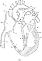
- Some mammalian hearts include four heart valves: a tricuspid valve 12, a pulmonary valve 14, an aortic valve 16, and a mitral valve 18, as seen in an example heart 10 illustrated in FIG. 1 .
- the purpose of the heart valves is to control blood flow into the heart 10 from the inferior vena cava 24 and/or the superior vena cava 26, through the heart 10, and out of the heart 10 into the major blood vessels connected to the heart 10, such as the aorta 20, the pulmonary artery 22, for example.
- Each heart valve may have a plurality of valve leaflets configured to shift between an open configuration permitting fluid flow through the heart valve in an antegrade direction, and a closed configuration wherein free edges of the valve leaflets coapt to substantially prevent fluid flow through the heart valve in a retrograde direction.
- the heart 10 may also include a left atrium 30, a left ventricle 40, a right atrium 50, and a right ventricle 60.
- the left ventricle 40 may include a first papillary muscle 42 attached to and/or extending from a wall of the left ventricle 40, a second papillary muscle 44 attached to and/or extending from the wall of the left ventricle 40, and a plurality of chordae 46 connecting the first papillary muscle 42 and the second papillary muscle 44 to the leaflets of the mitral valve 18.
- blood is permitted to pass or flow downstream through the heart valve (e.g., from an atrium to a ventricle, from a ventricle to an artery, etc.) when the heart valve is open (e.g., during diastole), and when the heart valve is closed (e.g., during systole), blood is prevented from passing or flowing back upstream through the heart valve (e.g., from a ventricle to an atrium, etc.).
- the heart valve e.g., from an atrium to a ventricle, from a ventricle to an artery, etc.
- a heart valve e.g., the mitral valve 18
- the mitral valve 18 fails to open and/or close properly such that blood is permitted to pass or flow back upstream through the heart valve (e.g., from a ventricle to an atrium, etc.).
- the defective heart valve may have leaflets that may not close, or may not be capable of closing, completely.
- secondary or functional mitral regurgitation may be a secondary effect of left ventricular dysfunction, where left ventricular dilatation and/or distension caused by ischemic or idiopathic cardiomyopathy, for example, results in annular dilatation and/or distension of the left ventricle 40 and papillary muscle displacement with subsequent leaflet tethering and insufficient coaptation of the mitral leaflets during systole, as seen in FIG. 1 for example.
- the first and second papillary muscles 42/44 are displaced outward and/or away from the mitral valve 18.
- Displacement of the first and second papillary muscles 42/44 adds tension to the chordae 46 connecting the first and second papillary muscles 42/44 to the mitral valve leaflets, and/or changes the tension on the chordae 46 with respect to a directional vector of the tension, resulting in leaflet tethering and/or insufficient coaptation of the mitral leaflets during systole.
- apparatus, medical devices, and/or methods that may be used to diagnose, treat, and/or repair a portion of the cardiovascular system.
- One possible remedy is an annular reduction procedure that may be performed to reduce an overall extent of the defective heart valve to bring the heart valve leaflets closer together.
- the annular reduction procedure may be performed in conjunction with a sub-valvular repair technique involving relocation of the papillary muscles to reduce leaflet tethering, thereby permitting the heart valve leaflets to more properly close the defective heart valve the passage of blood.
- the disclosed mitral regurgitation treatment method(s) and associated medical device(s) may be performed/used percutaneously via minimally-invasive intravascular techniques, or in an alternative method, using open-heart surgical methods.
- the device(s) and method(s) disclosed herein may also provide a number of additional desirable features and/or benefits as described in more detail below.
- the discussion below is directed toward repairing the mitral valve 18 and will be so described in the interest of brevity. This, however, is not intended to be limiting as the skilled person will recognize that the following discussion may also apply to the aortic valve 16 or another heart valve (e.g., the tricuspid valve 12, the pulmonary valve 14, etc.) with no or minimal changes to the structure and/or scope of the disclosure.
- a mitral regurgitation treatment system may reposition the first papillary muscle 42 and/or the second papillary muscle 44 relative to each other, relative to the wall of the left ventricle 40, and/or relative to the mitral valve 18 and/or the annulus of the mitral valve 18.
- the mitral regurgitation treatment system may pull the first papillary muscle 42 closer to the second papillary muscle 44.
- pulling the first papillary muscle 42 closer to the second papillary muscle 44 may also relocate the wall of the left ventricle 40, thereby reducing and/or eliminating the magnitude of dilatation and/or distension of the left ventricle 40, which also serves to reduce tension on the chordae 46, reduce leaflet tethering, and improves coaptation of the mitral leaflets during systole.
- pulling the first papillary muscle 42 closer to the second papillary muscle 44 may have limited effect upon the wall of the left ventricle 40 but may still reduce tension on the chordae 46, reduce leaflet tethering, and improves coaptation of the mitral leaflets during systole due to relocation of the first papillary muscle 42 and the second papillary muscle 44 closer to each other and/or the mitral valve 18.
- FIG. 2 illustrates selected aspects of an example method, not forming part of the invention, of treating mitral regurgitation.
- the method may include advancing a distal end 102 of an outer sheath 100 of a mitral regurgitation treatment system intravascularly to the left ventricle 40 of the heart 10.
- the outer sheath 100 of the mitral regurgitation treatment system may be inserted through a femoral artery and advanced in a retrograde direction (e.g., upstream) through the aorta 20 and the aortic valve 16 into the left ventricle 40 of the heart 10.
- a retrograde direction e.g., upstream
- Alternative percutaneous approaches including but not limited to transseptal access, as well as additional alternative methods including but not limited to an apical approach, are also contemplated.
- the outer sheath 100 has a lumen extending to the distal end 102 of the outer sheath 100.
- the lumen may extend completely through the outer sheath 100 to a proximal end of the outer sheath 100.
- a proximal end of the lumen may exit the outer sheath 100 distal of the proximal end of the outer sheath 100.
- the distal end 102 and/or a distal portion of the outer sheath 100 may be steerable to facilitate navigation and treatment procedures.
- the distal end 102 and/or the distal portion of the outer sheath 100 may be steerable to direct an opening from the lumen toward the first papillary muscle 42 and/or the second papillary muscle 44, as discussed herein.
- the proximal end of the outer sheath 100 may be disposed and/or be configured to be manipulated by a user outside of a patient's anatomy.
- the mitral regurgitation treatment system includes an intermediate sheath 110 slidably disposed within the lumen of the outer sheath 100.
- the intermediate sheath 110 a proximal portion of which may be seen in FIG. 2 adjacent the proximal end of the outer sheath 100, has a lumen extending to a distal end 112 of the intermediate sheath 110 and a tissue grasping mechanism 120 disposed at the distal end 112 of the intermediate sheath 110, as seen in FIG. 3 for example. Additional and/or alternative forms for the tissue grasping mechanism 120 may be seen in FIGS.
- tissue grasping mechanism 220 e.g., tissue grasping mechanism 220
- 7 e.g., tissue grasping mechanism 320
- 12 e.g., tissue grasping mechanism 290
- 13 e.g., tissue grasping mechanism 294
- the tissue grasping mechanism 120 may include a first prong 122 and a second prong 124 each fixedly attached to the distal end 112 of the intermediate sheath 110, as seen in FIG. 3 for example.
- the first prong 122 and the second prong 124 may be integrally formed with the intermediate sheath 110.
- the first prong 122 and the second prong 124 may each be at least partially embedded within a wall of the intermediate sheath 110.
- a proximal end of each of the first prong 122 and the second prong 124 may be attached, affixed, and/or secured to an outer surface of the intermediate sheath 110.
- the first prong 122 and the second prong 124 of the tissue grasping mechanism 120 may be configured to shift between a grasping configuration, shown in FIG. 4 for example, and an open configuration (e.g., FIG. 3 ).
- the first prong 122 and the second prong 124 of the tissue grasping mechanism 120 may be biased toward the open configuration when unconstrained, such as when disposed outside of the outer sheath 100, for example.
- the first prong 122 and the second prong 124 may be self-biased toward the open configuration when unconstrained.
- a gap 125A between a distal end of the first prong 122 and a distal end of the second prong 124, and more particularly a gap 125B between a first barb 126 on the first prong 122 extending toward the second prong 124 and a second barb 127 on the second prong 124 extending toward the first prong 122, is greater than an outer extent of the outer sheath 100 measured across the gap 125A/125B and/or normal to a longitudinal axis of the outer sheath 100.
- the gap 125A/125B may permit the first prong 122 and the second prong 124 of the to fit around and/or encompass at least a portion of the first papillary muscle 42 and/or the second papillary muscle 44, as seen in FIG. 3 .
- the tissue grasping mechanism 120 may be configured to hold and stabilize the first papillary muscle 42 and/or the second papillary muscle 44, as seen in FIG. 4 .
- the outer sheath 100 may be advanced distally while the intermediate sheath 110 and/or the tissue grasping mechanism 120 is maintained in a static position, and/or the intermediate sheath 110 and/or the tissue grasping mechanism 120 may be retracted proximally while the outer sheath 100 is maintained in a static position, such that relative translation between the outer sheath 100 and the intermediate sheath 110 and/or the tissue grasping mechanism 120 moves the distal end 102 of the outer sheath 100 over the first prong 122 and the second prong 124 of the tissue grasping mechanism 120, thereby urging the first prong 122 and the second prong 124 towards each other and/or the grasping configuration.
- the first papillary muscle 42 and/or the second papillary muscle 44 may be pinched, squeezed, and/or otherwise held between the first prong 122 and the second prong 124 of the tissue grasping mechanism 120.
- An anchor may then be inserted into and/or through the papillary muscle from an inner sheath 130, as described herein.
- FIGS. 5 and 6 illustrate an alternative configuration of a tissue grasping mechanism 220 disposed at the distal end 112 of the intermediate sheath 110.
- the tissue grasping mechanism 220 may include a first prong 222 and a second prong 224 configured to shift between a grasping configuration, shown in FIG. 6 for example, and an open configuration (e.g., FIG. 5 ).
- the first prong 222 and the second prong 224 of the tissue grasping mechanism 220 may be biased toward the open configuration when unconstrained, such as when disposed outside of the outer sheath 100, for example.
- the first prong 222 and the second prong 224 may be self-biased toward the open configuration when unconstrained.
- a gap 225A between a distal end of the first prong 222 and a distal end of the second prong 224 is greater than an outer extent of the outer sheath 100 measured across the gap 225A/225B and/or normal to a longitudinal axis of the outer sheath 100.
- the gap 225A/225B may permit the first prong 222 and the second prong 224 of the to fit around and/or encompass at least a portion of the first papillary muscle 42 and/or the second papillary muscle 44, as seen in FIG. 5 .
- the tissue grasping mechanism 220 may be configured to hold and stabilize the first papillary muscle 42 and/or the second papillary muscle 44, as seen in FIG. 6 .
- the outer sheath 100 may be maintained in a static position, and an actuator element 228 extending proximally from the tissue grasping mechanism 120 to an actuation position (e.g., FIG.
- proximate a proximal end of the intermediate sheath 110 may be retracted proximally, such that relative translation between the outer sheath 100 and actuator element 228 and/or the tissue grasping mechanism 220 urges the first prong 222 and the second prong 224 of the tissue grasping mechanism 220 towards each other and/or the grasping configuration.
- tension applied to the actuator element 228 may urge the first prong 222 and the second prong 224 towards each other and/or the grasping configuration by translating the tissue grasping mechanism 220 into the distal end 112 of the intermediate sheath 110.
- first prong 222 and the second prong 224 may be hingedly connected proximate a proximal end of the first prong 222 and the second prong 224, and the actuator element 228 may be connected to each of the first prong 222 and the second prong 224 distal of the hinged connection such that tension applied to the actuator element 228 may urge the first prong 222 and the second prong 224 towards each other and/or the grasping configuration by causing the first prong 222 and the second prong 224 to pivot towards each other and/or toward the grasping configuration at the hinged connection.
- the first papillary muscle 42 and/or the second papillary muscle 44 may be pinched, squeezed, and/or otherwise held between the first prong 222 and the second prong 224 of the tissue grasping mechanism 220.
- An anchor may then be inserted into and/or through the papillary muscle from an inner sheath, as described herein.
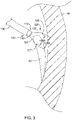
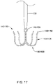
- the intermediate sheath 110 may include a tissue grasping mechanism 320 at the distal end 112 of the intermediate sheath 110.
- the tissue grasping mechanism 320 may include a curved member 322 fixedly attached to the distal end 112 of the intermediate sheath 110, as seen in FIG. 7 for example.
- the curved member 322 may be integrally formed with the intermediate sheath 110.
- the curved member 322 may be at least partially embedded within a wall of the intermediate sheath 110.
- a proximal end of the curved member 322 may be attached, affixed, and/or secured to an outer surface of the intermediate sheath 110.
- Various known means of attachment may be used, including but not limited to, adhesives, shrink wrap, welding, mechanical attachment, etc.
- the curved member 322 may be configured to shift between a delivery configuration, wherein the curved member 322 is constrained by and straightened by the outer sheath 100, and a curved configuration, wherein when the curved member 322 is unconstrained, the curved member 322 is biased towards the curved configuration and/or shape, as illustrated in FIG. 7 for example.
- the curved member 322 may be self-biased towards the curved configuration.
- the curved member 322 may be formed from a shape memory alloy and/or may be heat set to the curved configuration and/or shape.
- the curved member 322 may be deployed and allowed/permitted to shift towards the curved configuration.
- the intermediate sheath 110 and/or the curved member 322 may be maneuvered within the left ventricle 40 to position the curved member 322 around the first papillary muscle 42 and/or the second papillary muscle 44, using a suitable imaging technique (e.g., ultrasound, etc.).
- the curved member 322 may be adapted and/or configured to extend around a majority of a circumference of the first papillary muscle 42 and/or the second papillary muscle 44 in the curved configuration.
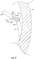
- an inner sheath 130 slidably disposed within the lumen of the intermediate sheath 110 may be extended out of the distal end 112 of the intermediate sheath 110 and into contact with an outer surface of the first papillary muscle 42 and/or the second papillary muscle 44, as seen in FIG. 8 for example.
- the first papillary muscle 42 and/or the second papillary muscle 44 may be pinched, squeezed, and/or otherwise held between inner sheath 130 and the curved member 322.
- distal advancement of the inner sheath 130 relative to the curved member 322 and/or the intermediate sheath 110 until a distal end 132 of the inner sheath 130 is positioned against the outer surface of the first papillary muscle 42 and/or the second papillary muscle 44 may grasp the first papillary muscle 42 and/or the second papillary muscle 44 to facilitate penetration of an anchor into the first papillary muscle 42 and/or the second papillary muscle 44 through an opening at the distal end 132 of the inner sheath 130, as discussed herein.
- a central longitudinal axis of the inner sheath 130 and/or the opening at the distal end 132 of the inner sheath 130 may be oriented substantially perpendicular to the outer surface of the first papillary muscle 42 and/or the second papillary muscle 44.
- the inner sheath 130 may include a port 136 extending through a side wall of the inner sheath 130 proximate the distal end 132 of the inner sheath 130, as seen in FIG. 9 for example, instead of and/or in addition to the opening at the distal end 132 of the inner sheath 130.
- the distal end 132 of the inner sheath 130 may be a closed distal end.
- distal advancement of the inner sheath 130 relative to the curved member 322 and/or the intermediate sheath 110 until the distal end 132 of the inner sheath 130 is positioned adjacent the first papillary muscle 42 and/or the second papillary muscle 44 may grasp the first papillary muscle 42 and/or the second papillary muscle 44 to facilitate penetration of an anchor into the first papillary muscle 42 and/or the second papillary muscle 44 through the port 136 at an angle generally perpendicular to a surface of the first papillary muscle 42 and/or the second papillary muscle 44 being penetrated, as discussed herein.
- the central longitudinal axis of the inner sheath 130 may be oriented substantially parallel to the outer surface of the first papillary muscle 42 and/or the second papillary muscle 44 being penetrated such that the port 136 generally abuts the outer surface of the first papillary muscle 42 and/or the second papillary muscle 44 being penetrated.
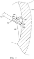
- a positioning sheath 180 may be slidably disposed within the lumen of the intermediate sheath 110.
- the positioning sheath 180 may include a distal end 182 and a port 186 extending through a side wall of the positioning sheath 180 proximate the distal end 182 of the positioning sheath 180, as seen in FIG. 10 for example.
- the distal end 182 of the positioning sheath 180 may be a closed distal end.
- the inner sheath 130 may be slidably disposed within a lumen of the positioning sheath 180.
- the lumen of the positioning sheath 180 and/or the port 186 of the positioning sheath 180 may be configured to direct the distal end 132 of the inner sheath 130 toward and/or into contact with the first papillary muscle 42 and/or the second papillary muscle 44 upon advancement of the inner sheath 130 relative to the positioning sheath 180, the intermediate sheath 110, and/or the curved member 322.
- the positioning sheath 180 may be configured to cooperate with the inner sheath 130 to facilitate penetration of an anchor into the first papillary muscle 42 and/or the second papillary muscle 44 through an opening at the distal end 132 of the inner sheath 130 at an angle generally perpendicular to a surface of the first papillary muscle 42 and/or the second papillary muscle 44 being penetrated, as discussed herein.
- a central longitudinal axis of the positioning sheath 180 may be oriented substantially parallel to the outer surface of the first papillary muscle 42 and/or the second papillary muscle 44 being penetrated such that the port 186 is positioned adjacent the outer surface of the first papillary muscle 42 and/or the second papillary muscle 44 being penetrated.
- the mitral regurgitation treatment system may include an intermediate sheath 280 slidably disposed within the lumen of the outer sheath 100.
- the intermediate sheath 280 may include a proximal portion disposed adjacent the proximal end of the outer sheath 100, a device lumen 284 extending to a distal end 282 of the intermediate sheath 280, and an anchoring lumen 288 extending to the distal end 282 of the intermediate sheath 280.
- the intermediate sheath 280 may include a port 286 extending through a side wall of the device lumen 284 and/or through a side wall of the intermediate sheath 280 proximate the distal end 282 of the intermediate sheath 280.
- the distal end 282 of the intermediate sheath 280 may be a closed distal end.
- the inner sheath 130 may be slidably disposed within the device lumen 284 of the intermediate sheath 280.
- the device lumen 284 of the intermediate sheath 280 and/or the port 286 of the intermediate sheath 280 may be configured to direct the distal end 132 of the inner sheath 130 toward and/or into contact with the first papillary muscle 42 and/or the second papillary muscle 44 upon advancement of the inner sheath 130 relative to the intermediate sheath 280.
- the intermediate sheath 280 may be configured to cooperate with the inner sheath 130 to facilitate penetration of an anchor into the first papillary muscle 42 and/or the second papillary muscle 44 through an opening at the distal end 132 of the inner sheath 130 at an angle generally perpendicular to a surface of the first papillary muscle 42 and/or the second papillary muscle 44 being penetrated, as discussed herein.
- a central longitudinal axis of the intermediate sheath 280 may be oriented substantially parallel to the outer surface of the first papillary muscle 42 and/or the second papillary muscle 44 being penetrated such that the port 286 is positioned adjacent the outer surface of the first papillary muscle 42 and/or the second papillary muscle 44 being penetrated.
- the intermediate sheath 280 may be configured to be positioned with the distal end 282 of the intermediate sheath 280 proximate and/or adjacent to a wall of the heart 10, as seen in FIG. 11 for example.
- the intermediate sheath 280 may include a tissue grasping mechanism 290 disposed at and/or extendable from the anchoring lumen 288 and/or the distal end 282 of the intermediate sheath 280, as seen in FIG. 12 for example. It should be understood that while aspects of the tissue grasping mechanism 290 is illustrated with respect to the first papillary muscle 42 in the interest of brevity, any and/or all aspects of the tissue grasping mechanism 290 may apply equally with respect to the second papillary muscle 44 and/or any procedures or method steps occurring with respect thereto.
- the tissue grasping mechanism 290 may be configured to secure the distal end 282 of the intermediate sheath 280 relative to the wall of the heart 10 and/or the first papillary muscle 42 and/or the second papillary muscle 44 being penetrated.
- the tissue grasping mechanism 290 may comprise a stabilizing needle configured to project distally from and/or configured to be extended out of the anchoring lumen 288 and/or the distal end 282 of the intermediate sheath 280 and into the wall of the heart 10 and/or a base of the first papillary muscle 42 and/or the second papillary muscle 44 being penetrated, as shown in FIG. 12 .
- the inner sheath 130 may be advanced distally relative to the intermediate sheath 280 and out of the port 286 and the distal end 132 of the inner sheath 130 may be advanced into contact and/or abutment with the first papillary muscle 42 and/or the second papillary muscle 44 to facilitate penetration of the anchor into the first papillary muscle 42 and/or the second papillary muscle 44 through the opening at the distal end 132 of the inner sheath 130 at an angle generally perpendicular to the surface of the first papillary muscle 42 and/or the second papillary muscle 44 being penetrated, as discussed herein.
- the intermediate sheath 280 may include a tissue grasping mechanism 294 disposed at and/or extendable from the anchoring lumen 288 and/or the distal end 282 of the intermediate sheath 280, as seen in FIG. 13 for example. It should be understood that while aspects of the tissue grasping mechanism 294 is illustrated with respect to the first papillary muscle 42 in the interest of brevity, any and/or all aspects of the tissue grasping mechanism 294 may apply equally with respect to the second papillary muscle 44 and/or any procedures or method steps occurring with respect thereto.
- the tissue grasping mechanism 294 may be configured to secure the distal end 282 of the intermediate sheath 280 relative to the wall of the heart 10 and/or the first papillary muscle 42 and/or the second papillary muscle 44 being penetrated, similar to the tissue grasping mechanism 290 discussed above.
- the tissue grasping mechanism 294 may comprise a suction member configured to project distally from and/or configured to be extended out of the anchoring lumen 288 and/or the distal end 282 of the intermediate sheath 280 and into contact with the wall of the heart 10 and/or a base of the first papillary muscle 42 and/or the second papillary muscle 44 being penetrated, as shown in FIG. 13 .
- the tissue grasping mechanism 294 and/or the suction member may expand radially outward in a distal direction, and the tissue grasping mechanism 294 and/or the suction member may have a generally conical or trumpet-like shape expanding to a greater outer extent further from the distal end 282 of the intermediate sheath 280.
- suction and/or negative pressure may be applied to the anchoring lumen 288 and/or the tissue grasping mechanism 294 and/or the suction member, thereby securing the tissue grasping mechanism 294 and/or the suction member and/or the intermediate sheath 280 to the wall of the heart 10 and/or the base of the first papillary muscle 42 and/or the second papillary muscle 44 being penetrated.
- the inner sheath 130 may be advanced distally relative to the intermediate sheath 280 and out of the port 286 and the distal end 132 of the inner sheath 130 may be advanced into contact and/or abutment with the first papillary muscle 42 and/or the second papillary muscle 44 to facilitate penetration of the anchor into the first papillary muscle 42 and/or the second papillary muscle 44 through the opening at the distal end 132 of the inner sheath 130 at an angle generally perpendicular to the surface of the first papillary muscle 42 and/or the second papillary muscle 44 being penetrated, as discussed herein.
- the inner sheath 130 may include at least one orientation marker 138 positioned adjacent the port 136 for determining an orientation of the port 136 relative to the first papillary muscle 42 and/or the second papillary muscle 44, as seen in FIGS. 14 and 15 .
- the positioning sheath 180 and/or the intermediate sheath 280 may similarly include at least one orientation marker 138 positioned adjacent the port 186 and/or the port 286, respectively, for determining an orientation of the portion 186/286 relative to the first papillary muscle 42 and/or the second papillary muscle 44, and any discussion related to the at least one orientation marker 138 and/or the port 136 may be applied equally to any and/or all embodiments having a port (e.g., 186, 286) through a side wall of a sheath or lumen.
- a port e.g., 186, 286
- the at least one orientation marker 138 may be radiopaque for identification during imaging.
- the at least one orientation marker 138 may comprise and/or may be a single orientation marker 138 framing or outlining the port 136 as viewed from a side of the inner sheath 130, as shown in FIG. 14 .
- the at least one orientation marker 138 may be distinguishable under imaging to determine the position of the inner sheath 130 and the port 136 relative to the first papillary muscle 42 and/or the second papillary muscle 44.
- the at least one orientation marker 138 may include three sides or legs, wherein a longest side or leg of the at least one orientation marker 138 may be oriented parallel with the central longitudinal axis of the inner sheath 130, and a shorter pair of sides or legs of the at least one orientation marker 138 may be oriented transversely relative to the central longitudinal axis of the inner sheath 130.
- the at least one orientation marker 138 may comprise and/or may be three or more individual orientation markers 138 framing or outlining the port 136 as viewed from the side of the inner sheath 130, as shown in FIG. 15 .
- the at least one orientation marker 138 may be distinguishable under imaging to determine the position of the inner sheath 130 and the port 136 relative to the first papillary muscle 42 and/or the second papillary muscle 44.
- one orientation marker 138 may be disposed on and/or within the side wall of the inner sheath 130 opposite the port 136, which two or more orientation markers 138 may be disposed on and/or within the side wall of the inner sheath 130 adjacent to and/or around an edge or circumference of the port 136.
- Other orientation marker configurations - for example, L-shaped, circular, etc. - are also contemplated.
- FIGS. 16 and 17 illustrate an example of a first/second anchor 140/150 suitable for use with the disclosed mitral regurgitation treatment system(s).
- the first/second anchor 140/150 may be used with any and/or all of the devices disclosed herein, as well as others.
- one or more additional anchors may be used in some embodiments.
- the first/second anchor 140/150 may include an eyelet 142/152 and a plurality of anchor legs 144/154 extending from the eyelet 142/152.
- the plurality of anchor legs 144/154 may extend from the eyelet 142/152 to free ends 148/158, the free ends 148/158 each having a tip configured to penetrate tissue.
- each free end 148/158 may be pointed and/or sharpened to easily pierce tissue. In some embodiments, the tip of each free end 148/158 may be slightly rounded, but still capable of easily piercing tissue without tearing said tissue. Combinations and/or other configurations of the tip are also contemplated.
- the first/second anchor 140/150 may be configured to penetrate and secure to the first papillary muscle 42 and/or the second papillary muscle 44.
- the first/second anchor 140/150 and/or the plurality of anchor legs 144/154 may be configured to shift from a delivery configuration when constrained by the inner sheath 130, wherein the plurality of anchor legs 144/154 is generally straightened and extends longitudinally away from the eyelet 142/152 in a first direction, and a deployed configuration when unconstrained by the inner sheath 130, wherein the plurality of anchor legs 144/154 extends in the first direction away from the eyelet 142/152 and then curves back on itself at a bend location 146/156 to extend in a second direction opposite the first direction from the bend location 146/156 to free ends 148/158.
- the first direction may be a distal direction and the second direction may be a proximal direction.
- the plurality of anchor legs 144/154 may extend in the second direction from the bend location 146/156 until the tip of each free end 148/158 is proximate to the eyelet 142/152 in the deployed configuration.
- the free ends 148/158 of the plurality of anchor legs 144/154 may point in a distal direction
- the free ends 148/158 of the plurality of anchor legs 144/154 may point in a proximal direction.
- the first/second anchor 140/150 may be biased towards the deployed configuration when unconstrained. In some embodiments, the first/second anchor 140/150 may be self-biased towards the deployed configuration with unconstrained. In at least some embodiments, the first/second anchor 140/150 may be formed from a shape memory material. Some suitable but non-limiting materials for the first/second anchor 140/150, for example metallic materials, polymer materials, composite materials, synthetic materials, etc., are described below.
- the mitral regurgitation treatment system may comprise an inner sheath 130 including a first anchor 140 disposed within a lumen of an inner sheath 130 in the delivery configuration.
- the first anchor 140 may be configured to penetrate and secure to the first papillary muscle 42.
- the mitral regurgitation treatment system may include a pusher member 160 (shown in FIG. 16 in phantom) slidably disposed within the lumen of the inner sheath 130.
- the pusher member 160 may be configured to expel the first anchor 140 from the lumen of the inner sheath 130 and/or to push/urge the first anchor 140 into the first papillary muscle 42.
- a proximal portion and/or the eyelet 142 of the first anchor 140 may be disposed within a lumen of the pusher member 160 in the delivery configuration.
- the tissue grasping mechanism 120/220/320 may be configured to hold and stabilize the first papillary muscle 42 for penetration and securement of the first anchor 140 to the first papillary muscle 42.
- the inner sheath 130 may further include a tethering element 170 disposed within the lumen of the inner sheath 130 and/or within a lumen of the pusher member 160.
- the tethering element 170 may engage with and/or be attached to the eyelet 142 of the first anchor 140.
- the tethering element 170 may extend proximally from the eyelet 142 of the first anchor 140.
- the tethering element 170 may take one or more of various forms known in the art - including, but not limited to, a suture, a filament, a wire, etc.
- the inner sheath 130 may be configured to extend and/or be advanced distally out of the distal end 112 of the intermediate sheath 110 and into contact and/or engagement with the first papillary muscle 42 and/or the second papillary muscle 44.
- the inner sheath 130 may be configured to extend and/or be advanced distally out of the distal end 112 of the intermediate sheath 110 while the tissue grasping mechanism 120/220/320/290/294 holds and stabilizes the first papillary muscle 42 and/or the second papillary muscle 44 and/or the distal end 282 of the intermediate sheath 280 to ensure proper positioning of a distal end 132 of the inner sheath 130 relative to the first papillary muscle 42 and/or the second papillary muscle 44 (e.g., FIGS. 4 , 6 , and 8-13 ).
- the first anchor 140 may be configured to shift toward the deployed configuration, shown in FIG. 17 for example.
- the inner sheath 130 may further include a second anchor 150 advanceable through the lumen of the inner sheath 130.
- the second anchor 150 may be configured to penetrate and secure to the second papillary muscle 44.
- the tissue grasping mechanism 120/220/320/290/294 may be configured to hold and stabilize the second papillary muscle 44 and/or the distal end 282 of the intermediate sheath 280 for penetration and securement of the second anchor 150 to the second papillary muscle 44.
- the first anchor 140 and the second anchor 150 may be advanceable through the inner sheath 130 in series.
- the first anchor 140 and the second anchor 150 may be advanceable through the inner sheath 130 in parallel.
- the first anchor 140 and the second anchor 150 may be advanceable through the inner sheath 130 separately.
- the first anchor 140 and the second anchor 150 may be advanceable through the inner sheath 130 together.
- the first anchor 140 and the second anchor 150 may be connectable to each other.
- the first anchor 140 and the second anchor 150 may be configured to be connected to each other after deployment from the inner sheath 130.
- the first anchor 140 and the second anchor 150 may be connected to each other by the tethering element 170.
- the tethering element 170 may engage with and/or be attached to the eyelet 152 of the second anchor 150.
- the tethering element 170 may extend proximally from the eyelet 152 of the second anchor 150.
- the tethering element 170 may be configured to extend between the first papillary muscle 42 and the second papillary muscle 44, and/or the eyelet 142 of the first anchor 140 and the eyelet 152 of the second anchor 150, in tension. In some embodiments, at least a portion of each of the first anchor 140 and the second anchor 150 is configured to extend transversely relative to the tethering element 170 when unconstrained by the inner sheath 130. In some embodiments, the first anchor 140 and the second anchor 150 may each include a separate and/or independent tethering element, and the separate and/or independent tethering elements may be connectable together. For example, the tethering element of the first anchor 140 may be connectable to the tethering element of the second anchor 150, such as by tying, adhesive(s), or other suitable means.
- FIG. 18 illustrates an alternative first/second anchor 240/250 disposed within the lumen of the inner sheath 130 in a delivery configuration.
- the distal end 132 of the inner sheath 130 may be configured to penetrate the first papillary muscle 42 and/or the second papillary muscle 44 in order to deploy the first/second anchor 240/250.
- the first/second anchor 240/250 may be oriented generally parallel to a central longitudinal axis of the inner sheath 130 and/or generally perpendicular to the outer surface of the first papillary muscle 42 and/or the second papillary muscle 44.
- first/second anchor 240/250 may be shaped and/or configured to pierce tissue as the first/second anchor 240/250 is advanced out of the distal end 132 of the inner sheath 130.
- first/second anchor 240/250 for example metallic materials, polymer materials, composite materials, synthetic materials, etc., are described below.
- a pusher member 260 may be slidably disposed within the lumen of the inner sheath 130.
- the pusher member 260 may be an elongate solid rod or shaft, however, other configurations are also contemplated.
- the pusher member 260 may be configured to expel the first/second anchor 240/250 from the lumen of the inner sheath 130.
- the first/second anchor 240/250 may be configured to shift to a deployed configuration, wherein the first/second anchor 240/250 is oriented generally perpendicular to the central longitudinal axis of the inner sheath 130 and/or generally parallel to and/or abutting the outer surface of the first papillary muscle 42 and/or the second papillary muscle 44.
- the tethering element 170 may extend from an eyelet 242/252 of the first/second anchor 240/250. Upon deployment, the tethering element 170 may extend through the first papillary muscle 42 and/or the second papillary muscle 44.
- the tethering element 170 may be configured to extend between the first papillary muscle 42 and the second papillary muscle 44, and/or the first anchor 240 and the second anchor 250, in tension. In some embodiments, the tethering element 170 may be configured to extend between the eyelet 242 of the first anchor 240 and the eyelet 252 of the second anchor 250, in tension. In some embodiments, at least a portion of each of the first anchor 240 and the second anchor 250 is configured to extend transversely relative to the tethering element 170 when unconstrained by the inner sheath 130.
- first anchor 240 and the second anchor 250 may each include a separate and/or independent tethering element, and the separate and/or independent tethering elements may be connectable together.
- the tethering element of the first anchor 240 may be connectable to the tethering element of the second anchor 250, such as by tying, adhesive(s), or other suitable means.
- a method, not forming part of the invention, for treating mitral regurgitation may include advancing the distal end 102 of the outer sheath 100 intravascularly to the left ventricle 40 of the heart 10, as shown in FIG. 2 and described herein.
- the distal end 102 of the outer sheath 100 may be positioned proximate the first papillary muscle 42.
- the method may include advancing the intermediate sheath 110/280 and/or the tissue grasping mechanism 120/220/320/290/294 out of the distal end 102 of the outer sheath 100 and into engagement with the first papillary muscle 42.
- the method may include grasping the first papillary muscle 42 of the left ventricle 40 using the tissue grasping mechanism 120/220/320/290/294, the tissue grasping mechanism 120/220/320/290/294 being configured to hold and stabilize the first papillary muscle 42 for penetration of the first anchor 140/240 into the first papillary muscle 42 from the inner sheath 130, the inner sheath 130 being slidably disposed within the lumen of the intermediate sheath 110/280.
- the method may include advancing the inner sheath 130 through the lumen of the intermediate sheath 110/280 and/or out of the distal end 112/282 of the intermediate sheath 110/280 proximate the first papillary muscle 42 while the tissue grasping mechanism 120/220/320/290/294 holds and stabilizes the first papillary muscle 42 relative to the outer sheath 100 and/or a wall of the left ventricle 40.
- the method may include advancing the first anchor 140/240 into the first papillary muscle 42 from within a lumen of the inner sheath 130, the first anchor 140/240 being configured to penetrate and secure to the first papillary muscle 42 of the left ventricle 40.
- the tethering element 170 may extend from the first anchor 140/240 into the distal end 132 of the inner sheath 130 and/or the distal end 102 of the outer sheath 100.
- the method may include releasing the first papillary muscle 42 of the left ventricle 40 from the tissue grasping mechanism 120/220/320/290/294 and/or withdrawing the tissue grasping mechanism 120/220/320/290/294 and/or the intermediate sheath 110/280 into the distal end 102 of the outer sheath 100, as seen in FIG. 19 for example.
- the method may include repositioning the distal end 102 of the outer sheath 100 adjacent the second papillary muscle 44 of the left ventricle 40, as shown in FIG. 20 .
- the method may include advancing the intermediate sheath 110/280 and/or the tissue grasping mechanism 120/220/320/290/294 out of the distal end 102 of the outer sheath 100 and into engagement with the second papillary muscle 44.
- the method may include grasping the second papillary muscle 44 of the left ventricle 40 using the tissue grasping mechanism 120/220/320/290/294, the tissue grasping mechanism 120/220/320/290/294 being configured to hold and stabilize the second papillary muscle 44 for penetration of the second anchor 150/250 into the second papillary muscle 44 from the inner sheath 130.
- the method may include advancing the inner sheath 130 through the lumen of the intermediate sheath 110/280 and/or out of the distal end 112 of the intermediate sheath 110 proximate the second papillary muscle 44 while the tissue grasping mechanism 120/220/320/290/294 holds and stabilizes the second papillary muscle 44 relative to the outer sheath 100 and/or a wall of the left ventricle 40.
- the method may include advancing the second anchor 150/250 into the second papillary muscle 44 from within a lumen of the inner sheath 130, the second anchor 150/250 being configured to penetrate and secure to the second papillary muscle 44 of the left ventricle 40.
- the tethering element 170 may extend from the second anchor 150/250 into the distal end 132 of the inner sheath 130 and/or the distal end 102 of the outer sheath 100, and/or the tethering element 170 may extend between the first anchor 140/240 and the second anchor 150/250.
- the method may include releasing the second papillary muscle 44 of the left ventricle 40 from the tissue grasping mechanism 120/220/320/290/294 and/or withdrawing the tissue grasping mechanism 120/220/320/290/294 and/or the intermediate sheath 110/280 into the distal end 102 of the outer sheath 100, as seen in FIG. 21 for example.
- the method may include translating the first papillary muscle 42 closer to the second papillary muscle 44 by tensioning the tethering element 170 between the first anchor 140/240 and the second anchor 150/250, as seen in FIG. 22 .
- the mitral regurgitation treatment system the tethering element 170 may draw, translate, and/or relocate the first papillary muscle 42 into contact with the second papillary muscle 44.
- a space between the first papillary muscle 42 and the second papillary muscle 44 may be eliminated and/or reduced to zero. This arrangement and/or configuration may be equally applied to any configuration and/or embodiment disclosed herein.
- the method may include connecting the tethering element of the first anchor 140/240 to the tethering element of the second anchor 140/240, as discussed herein, such as by tying the tethering element of the first anchor 140/240 together with the tethering element of the second anchor 140/240, or by fixing the tethering element of the first anchor 140/240 to the tethering element of the second anchor 140/240 with an adhesive, or by other suitable means.
- the materials that can be used for the various components of the outer sheath 100, the intermediate sheath 110/280, the tissue grasping mechanism 120/220/320/290/294, the inner sheath 130, the first anchor 140/240, the second anchor 150/250, the pusher member 160/260, the tethering element 170, the positioning sheath 180, etc. (and/or other systems or components disclosed herein) and the various elements thereof disclosed herein may include those commonly associated with medical devices.
- the following discussion makes reference to the outer sheath 100, the intermediate sheath 110/280, the tissue grasping mechanism 120/220/320/290/294, the inner sheath 130, the first anchor 140/240, the second anchor 150/250, the pusher member 160/260, the tethering element 170, the positioning sheath 180, etc.
- this is not intended to limit the devices and methods described herein, as the discussion may be applied to other elements, members, components, or devices disclosed herein, such as, but not limited to, the first prong 122/222, the second prong 124/224, the curved member 322, the plurality of anchor legs 144/154, etc. and/or elements or components thereof.
- the outer sheath 100, the intermediate sheath 110/280, the tissue grasping mechanism 120/220/320/290/294, the inner sheath 130, the first anchor 140/240, the second anchor 150/250, the pusher member 160/260, the tethering element 170, the positioning sheath 180, etc., and/or components thereof may be made from a metal, metal alloy, polymer (some examples of which are disclosed below), a metal-polymer composite, ceramics, combinations thereof, and the like, or other suitable material.
- suitable metals and metal alloys include stainless steel, such as 444V, 444L, and 314LV stainless steel; mild steel; nickel-titanium alloy such as linear-elastic and/or super-elastic nitinol; other nickel alloys such as nickel-chromium-molybdenum alloys (e.g., UNS: N06625 such as INCONEL ® 625, UNS: N06022 such as HASTELLOY ® C-22 ® , UNS: N10276 such as HASTELLOY ® C276 ® , other HASTELLOY ® alloys, and the like), nickel-copper alloys (e.g., UNS: N04400 such as MONEL ® 400, NICKEL VAC ® 400, NICORROS ® 400, and the like), nickel-cobalt-chromium-molybdenum alloys (e.g., UNS: R44035 such as MP35-N ® and the like), nickel
- Linear elastic and/or non-super-elastic nitinol may be distinguished from super elastic nitinol in that the linear elastic and/or non-super-elastic nitinol does not display a substantial "superelastic plateau” or “flag region” in its stress/strain curve like super elastic nitinol does.
- linear elastic and/or non-super-elastic nitinol as recoverable strain increases, the stress continues to increase in a substantially linear, or a somewhat, but not necessarily entirely linear relationship until plastic deformation begins or at least in a relationship that is more linear than the super elastic plateau and/or flag region that may be seen with super elastic nitinol.
- linear elastic and/or non-super-elastic nitinol may also be termed "substantially" linear elastic and/or non-super-elastic nitinol.
- linear elastic and/or non-super-elastic nitinol may also be distinguishable from super elastic nitinol in that linear elastic and/or non-super-elastic nitinol may accept up to about 2-5% strain while remaining substantially elastic (e.g., before plastically deforming) whereas super elastic nitinol may accept up to about 8% strain before plastically deforming. Both of these materials can be distinguished from other linear elastic materials such as stainless steel (that can also be distinguished based on its composition), which may accept only about 0.2 to 0.44 percent strain before plastically deforming.
- the linear elastic and/or non-super-elastic nickel-titanium alloy is an alloy that does not show any martensite/austenite phase changes that are detectable by differential scanning calorimetry (DSC) and dynamic metal thermal analysis (DMTA) analysis over a large temperature range.
- DSC differential scanning calorimetry
- DMTA dynamic metal thermal analysis
- the mechanical bending properties of such material may therefore be generally inert to the effect of temperature over this very broad range of temperature.
- the mechanical bending properties of the linear elastic and/or non-super-elastic nickel-titanium alloy at ambient or room temperature are substantially the same as the mechanical properties at body temperature, for example, in that they do not display a super-elastic plateau and/or flag region.
- the linear elastic and/or non-super-elastic nickel-titanium alloy maintains its linear elastic and/or non-super-elastic characteristics and/or properties.
- the linear elastic and/or non-super-elastic nickel-titanium alloy may be in the range of about 50 to about 60 weight percent nickel, with the remainder being essentially titanium. In some embodiments, the composition is in the range of about 54 to about 57 weight percent nickel.
- a suitable nickel-titanium alloy is FHP-NT alloy commercially available from Furukawa Techno Material Co. of Kanagawa, Japan. Other suitable materials may include ULTANIUM TM (available from Neo-Metrics) and GUM METAL TM (available from Toyota).
- a superelastic alloy for example a superelastic nitinol can be used to achieve desired properties.
- portions or all of the outer sheath 100, the intermediate sheath 110/280, the tissue grasping mechanism 120/220/320/290/294, the inner sheath 130, the first anchor 140/240, the second anchor 150/250, the pusher member 160/260, the tethering element 170, the positioning sheath 180, etc., and/or components thereof, may also be doped with, made of, or otherwise include a radiopaque material.
- Radiopaque materials are understood to be materials capable of producing a relatively bright image on a fluoroscopy screen or another imaging technique during a medical procedure.
- radiopaque materials can include, but are not limited to, gold, platinum, palladium, tantalum, tungsten alloy, polymer material loaded with a radiopaque filler, and the like.
- radiopaque marker bands and/or coils may also be incorporated into the design of the outer sheath 100, the intermediate sheath 110/280, the tissue grasping mechanism 120/220/320/290/294, the inner sheath 130, the first anchor 140/240, the second anchor 150/250, the pusher member 160/260, the tethering element 170, the positioning sheath 180, etc. to achieve the same result.
- a degree of Magnetic Resonance Imaging (MRI) compatibility is imparted into the outer sheath 100, the intermediate sheath 110/280, the tissue grasping mechanism 120/220/320/290/294, the inner sheath 130, the first anchor 140/240, the second anchor 150/250, the pusher member 160/260, the tethering element 170, the positioning sheath 180, etc.
- MRI Magnetic Resonance Imaging
- the outer sheath 100, the intermediate sheath 110/280, the tissue grasping mechanism 120/220/320/290/294, the inner sheath 130, the first anchor 140/240, the second anchor 150/250, the pusher member 160/260, the tethering element 170, the positioning sheath 180, etc., and/or components or portions thereof may be made of a material that does not substantially distort the image and create substantial artifacts (e.g., gaps in the image). Certain ferromagnetic materials, for example, may not be suitable because they may create artifacts in an MRI image.
- the outer sheath 100, the intermediate sheath 110/280, the tissue grasping mechanism 120/220/320/290/294, the inner sheath 130, the first anchor 140/240, the second anchor 150/250, the pusher member 160/260, the tethering element 170, the positioning sheath 180, etc., or portions thereof, may also be made from a material that the MRI machine can image.
- Some materials that exhibit these characteristics include, for example, tungsten, cobalt-chromium-molybdenum alloys (e.g., UNS: R44003 such as ELGILOY ® , PHYNOX ® , and the like), nickel-cobalt-chromium-molybdenum alloys (e.g., UNS: R44035 such as MP35-N ® and the like), nitinol, and the like, and others.
- cobalt-chromium-molybdenum alloys e.g., UNS: R44003 such as ELGILOY ® , PHYNOX ® , and the like
- nickel-cobalt-chromium-molybdenum alloys e.g., UNS: R44035 such as MP35-N ® and the like
- nitinol and the like, and others.
- the outer sheath 100, the intermediate sheath 110/280, the tissue grasping mechanism 120/220/320/290/294, the inner sheath 130, the first anchor 140/240, the second anchor 150/250, the pusher member 160/260, the tethering element 170, the positioning sheath 180, etc., and/or portions thereof, may be made from or include a polymer or other suitable material.
- suitable polymers may include polytetrafluoroethylene (PTFE), ethylene tetrafluoroethylene (ETFE), fluorinated ethylene propylene (FEP), polyoxymethylene (POM, for example, DELRIN ® available from DuPont), polyether block ester, polyurethane (for example, Polyurethane 85A), polypropylene (PP), polyvinylchloride (PVC), polyether-ester (for example, ARNITEL ® available from DSM Engineering Plastics), ether or ester based copolymers (for example, butylene/poly(alkylene ether) phthalate and/or other polyester elastomers such as HYTREL ® available from DuPont), polyamide (for example, DURETHAN ® available from Bayer or CRISTAMID ® available from Elf Atochem), elastomeric polyamides, block polyamide/ethers, polyether block amide (PEBA, for example available under the trade name PEBAX ®
- the outer sheath 100, the intermediate sheath 110/280, the tissue grasping mechanism 120/220/320/290/294, the inner sheath 130, the first anchor 140/240, the second anchor 150/250, the pusher member 160/260, the tethering element 170, the positioning sheath 180, etc. may include and/or be formed from a textile material.
- suitable textile materials may include synthetic yarns that may be flat, shaped, twisted, textured, pre-shrunk or un-shrunk.
- Synthetic biocompatible yarns suitable for use in the present invention include, but are not limited to, polyesters, including polyethylene terephthalate (PET) polyesters, polypropylenes, polyethylenes, polyurethanes, polyolefins, polyvinyls, polymethylacetates, polyamides, naphthalene dicarboxylene derivatives, natural silk, and polytetrafluoroethylenes.
- PET polyethylene terephthalate
- polypropylenes polyethylenes
- polyethylenes polyurethanes
- polyolefins polyvinyls
- polymethylacetates polyamides
- naphthalene dicarboxylene derivatives polymethylacetates
- polyamides naphthalene dicarboxylene derivatives
- natural silk and polytetrafluoroethylenes.
- at least one of the synthetic yarns may be a metallic yarn or a glass or ceramic yarn or fiber.
- Useful metallic yarns include those yarns made from or containing
- the yarns are made from thermoplastic materials including, but not limited to, polyesters, polypropylenes, polyethylenes, polyurethanes, polynaphthalenes, polytetrafluoroethylenes, and the like.
- the yarns may be of the multifilament, monofilament, or spun-types.
- the type and denier of the yarn chosen may be selected in a manner which forms a biocompatible and implantable prosthesis and, more particularly, a vascular structure having desirable properties.
- the outer sheath 100, the intermediate sheath 110/280, the tissue grasping mechanism 120/220/320/290/294, the inner sheath 130, the first anchor 140/240, the second anchor 150/250, the pusher member 160/260, the tethering element 170, the positioning sheath 180, etc. may include and/or be treated with a suitable therapeutic agent.
- suitable therapeutic agents may include anti-thrombogenic agents (such as heparin, heparin derivatives, urokinase, and PPack (dextrophenylalanine proline arginine chloromethylketone)); anti-proliferative agents (such as enoxaparin, angiopeptin, monoclonal antibodies capable of blocking smooth muscle cell proliferation, hirudin, and acetylsalicylic acid); anti-inflammatory agents (such as dexamethasone, prednisolone, corticosterone, budesonide, estrogen, sulfasalazine, and mesalamine); antineoplastic/antiproliferative/anti-mitotic agents (such as paclitaxel, 5-fluorouracil, cisplatin, vinblastine, vincristine, epothilones, endostatin, angiostatin and thymidine kinase inhibitors); anesthetic agents (such as lido
Claims (15)
- Système pour traiter la régurgitation mitrale, comprenant :une gaine externe (100) ayant une lumière s'étendant jusqu'à une extrémité distale (102) de la gaine externe (100),une gaine intermédiaire (110) disposée de manière coulissante à l'intérieur de la lumière de la gaine externe (100), la gaine intermédiaire ayant une lumière s'étendant jusqu'à une extrémité distale (112) de la gaine intermédiaire (110), et caractérisé parune gaine interne disposée de manière coulissante à l'intérieur de la lumière de la gaine intermédiaire, la gaine interne comprenant une première ancre disposée à l'intérieur d'une lumière de la gaine interne, la première ancre étant configurée pour pénétrer et se fixer à un premier muscle papillaire ;la gaine intermédiaire (110) comprenant un mécanisme de préhension de tissu (120, 220, 320, 290, 294) à l'extrémité distale (112) de la gaine intermédiaire (110), le mécanisme de préhension de tissu (120, 220, 320, 290, 294) étant configuré pour maintenir et stabiliser le premier muscle papillaire pour la pénétration et la fixation de la première ancre au premier muscle papillaire.
- Système selon la revendication 1, le mécanisme de préhension de tissu (120, 220, 320, 290, 294) comprenant une première branche (122, 222) et une seconde branche (124, 224), chacune étant fixée à l'extrémité distale (112) de la gaine intermédiaire (110) ;
la première branche (122, 222) et la seconde branche (124, 224) étant configurées pour se déplacer entre une configuration de préhension et une configuration ouverte, la première branche (122, 224) et la seconde branche (124, 224) étant sollicitées vers la configuration ouverte lorsqu'elles ne sont pas contraintes. - Système selon la revendication 2, dans la configuration ouverte, un espace (125A, 225A, 225B) entre une extrémité distale de la première branche (122, 222) et une extrémité distale de la seconde branche (124, 224) étant supérieur à une étendue externe de la gaine externe (100).
- Système selon la revendication 3, la translation relative de la gaine externe (100) et du mécanisme de préhension de tissu (120, 220, 320, 290, 294) l'un vers l'autre poussant la première branche (122, 222) et la seconde branche (124, 224) vers la configuration de préhension.
- Système selon la revendication 3, la gaine intermédiaire (110) comprenant un élément d'actionnement (228) s'étendant de manière proximale depuis le mécanisme de préhension de tissu (220) jusqu'à une position d'actionnement à proximité d'une extrémité proximale de la gaine intermédiaire (110).
- Système selon la revendication 5, la tension appliquée à l'élément actionneur (228) poussant la première branche (222) et la seconde branche (224) vers la configuration de préhension.
- Système selon la revendication 1, le mécanisme de préhension de tissu (320) comprenant un élément incurvé (332) fixé à l'extrémité distale (112) de la gaine intermédiaire (110), l'élément incurvé (320) étant configuré pour s'étendre autour d'une majorité d'une circonférence du premier muscle papillaire (42).
- Système selon la revendication 7, l'avancement distal de la gaine interne (130) par rapport à l'élément incurvé (320) jusqu'à ce qu'une extrémité distale de la gaine interne (130) soit positionnée contre le premier muscle papillaire (42) saisissant le premier muscle papillaire (42) pour faciliter la pénétration de la première ancre (140) dans le premier muscle papillaire (42) à travers l'extrémité distale (132) de la gaine interne (130).
- Système selon la revendication 7, la gaine interne (130) comprenant un orifice (136) s'étendant à travers une paroi latérale de la gaine interne (130) à proximité d'une extrémité distale (132) de la gaine interne (130), et au moins un marqueur d'orientation positionné de manière adjacente à l'orifice (136) pour déterminer une orientation de l'orifice par rapport au premier muscle papillaire (42) ;
l'avancement distal de la gaine interne (130) par rapport à l'élément incurvé (320) jusqu'à ce que l'extrémité distale (132) de la gaine interne (130) soit positionnée de manière adjacente au premier muscle papillaire (42) saisissant le premier muscle papillaire (42) pour faciliter la pénétration de la première ancre (140) dans le premier muscle papillaire (42) à travers l'orifice selon un angle généralement perpendiculaire à une surface du premier muscle papillaire (42) en cours de pénétration. - Système selon la revendication 9, l'extrémité distale (132) de la gaine interne (130) étant une extrémité distale fermée.
- Système selon l'une quelconque des revendications 1 à 10, comprenant en outre une seconde ancre (150) pouvant être avancée à travers la lumière de la gaine interne (130), la seconde ancre (150) étant configurée pour pénétrer et se fixer à un second muscle papillaire (44).
- Système selon la revendication 11, la première ancre (140) et la seconde ancre (150) pouvant être reliées l'une à l'autre.
- Système selon la revendication 12, la première ancre (140) et la seconde ancre (150) étant configurées pour être reliées l'une à l'autre après le déploiement de la gaine interne (130).
- Système selon la revendication 12, la première ancre (140) et la seconde ancre (150) étant reliées l'une à l'autre par un élément d'attache (170).
- Système selon l'une quelconque des revendications 11 à 14, le mécanisme de préhension de tissu (120, 220, 320, 290, 294) étant configuré pour maintenir et stabiliser le second muscle papillaire (44) pour la pénétration et la fixation de la seconde ancre (150) au second muscle papillaire (44).
Applications Claiming Priority (2)
| Application Number | Priority Date | Filing Date | Title |
|---|---|---|---|
| US201862675118P | 2018-05-22 | 2018-05-22 | |
| PCT/US2019/033572 WO2019226803A1 (fr) | 2018-05-22 | 2019-05-22 | Relocalisation percutanée de muscle papillaire |
Publications (2)
| Publication Number | Publication Date |
|---|---|
| EP3796876A1 EP3796876A1 (fr) | 2021-03-31 |
| EP3796876B1 true EP3796876B1 (fr) | 2022-07-27 |
Family
ID=66999901
Family Applications (1)
| Application Number | Title | Priority Date | Filing Date |
|---|---|---|---|
| EP19732495.7A Active EP3796876B1 (fr) | 2018-05-22 | 2019-05-22 | Relocalisation percutanée de muscle papillaire |
Country Status (3)
| Country | Link |
|---|---|
| US (3) | US11147673B2 (fr) |
| EP (1) | EP3796876B1 (fr) |
| WO (1) | WO2019226803A1 (fr) |
Cited By (1)
| Publication number | Priority date | Publication date | Assignee | Title |
|---|---|---|---|---|
| US11617650B2 (en) | 2012-05-30 | 2023-04-04 | Neovasc Tiara Inc. | Methods and apparatus for loading a prosthesis onto a delivery system |
Families Citing this family (11)
| Publication number | Priority date | Publication date | Assignee | Title |
|---|---|---|---|---|
| US9554897B2 (en) | 2011-04-28 | 2017-01-31 | Neovasc Tiara Inc. | Methods and apparatus for engaging a valve prosthesis with tissue |
| WO2018178901A2 (fr) | 2017-03-28 | 2018-10-04 | Cardiac Success Ltd. | Procédé permettant d'améliorer le fonctionnement cardiaque |
| US11318018B2 (en) | 2017-03-28 | 2022-05-03 | Cardiac Success Ltd. | Method of improving cardiac function |
| WO2019036810A1 (fr) | 2017-08-25 | 2019-02-28 | Neovasc Tiara Inc. | Prothèse de valvule mitrale transcathéter à déploiement séquentiel |
| EP3681439B1 (fr) * | 2017-09-12 | 2021-07-28 | Boston Scientific Scimed, Inc. | Relocalisation percutanée de muscle papillaire |
| EP3700470B1 (fr) | 2017-10-23 | 2024-04-17 | Cardiac Success Ltd. | Bande de muscles papillaires à auto-verrouillage réglable |
| US11464638B2 (en) | 2017-10-23 | 2022-10-11 | Cardiac Success Ltd | Adjustable self-locking papillary muscle band |
| CA3118599A1 (fr) | 2018-11-08 | 2020-05-14 | Neovasc Tiara Inc. | Deploiement ventriculaire d'une prothese de valvule mitrale transcatheter |
| EP3946163A4 (fr) | 2019-04-01 | 2022-12-21 | Neovasc Tiara Inc. | Valve prothétique déployable de manière contrôlable |
| EP3972673A4 (fr) | 2019-05-20 | 2023-06-07 | Neovasc Tiara Inc. | Dispositif d'introduction avec mécanisme d'hémostase |
| AU2020295566B2 (en) | 2019-06-20 | 2023-07-20 | Neovasc Tiara Inc. | Low profile prosthetic mitral valve |
Family Cites Families (216)
| Publication number | Priority date | Publication date | Assignee | Title |
|---|---|---|---|---|
| US3130418A (en) | 1960-11-25 | 1964-04-28 | Louis R Head | Artificial heart valve and method for making same |
| JPS5590013A (en) | 1978-12-27 | 1980-07-08 | Nippon Electric Co | Conductor |
| GB9012716D0 (en) | 1990-06-07 | 1990-08-01 | Frater Robert W M | Mitral heart valve replacements |
| JPH0590013A (ja) | 1991-09-27 | 1993-04-09 | Toshiba Lighting & Technol Corp | 周波数制御部品の製造方法 |
| BR9202905A (pt) | 1992-07-28 | 1994-02-01 | Mario Osvaldo Vrandecic Peredo | Bioprotese heterologa total para uso em posicao mitral e tricuspide |
| DE4234127C2 (de) | 1992-10-09 | 1996-02-22 | Herbert Dr Vetter | Herzklappenprothese |
| US6074417A (en) | 1992-11-16 | 2000-06-13 | St. Jude Medical, Inc. | Total mitral heterologous bioprosthesis to be used in mitral or tricuspid heart replacement |
| US5480424A (en) | 1993-11-01 | 1996-01-02 | Cox; James L. | Heart valve replacement using flexible tubes |
| WO1997024083A1 (fr) | 1993-11-01 | 1997-07-10 | Cox James L | Remplacement de valvule cardiaque a l'aide de tubes souples |
| US5713950A (en) | 1993-11-01 | 1998-02-03 | Cox; James L. | Method of replacing heart valves using flexible tubes |
| US5554184A (en) | 1994-07-27 | 1996-09-10 | Machiraju; Venkat R. | Heart valve |
| US5662704A (en) | 1995-12-01 | 1997-09-02 | Medtronic, Inc. | Physiologic mitral valve bioprosthesis |
| CA2248643A1 (fr) | 1996-04-08 | 1997-10-16 | Medtronic, Inc. | Methode pour fixer une bioprothese de valvule mitrale physiologique |
| US5989284A (en) | 1997-02-18 | 1999-11-23 | Hearten Medical, Inc. | Method and device for soft tissue modification |
| US6332893B1 (en) | 1997-12-17 | 2001-12-25 | Myocor, Inc. | Valve to myocardium tension members device and method |
| RU2141259C1 (ru) | 1998-04-06 | 1999-11-20 | Московская медицинская академия им.И.М.Сеченова | Способ хирургического лечения гипертрофической обструктивной кардиомиопатии с сопутствующей митральной недостаточностью |
| US6547821B1 (en) | 1998-07-16 | 2003-04-15 | Cardiothoracic Systems, Inc. | Surgical procedures and devices for increasing cardiac output of the heart |
| US6267781B1 (en) | 1998-08-31 | 2001-07-31 | Quantum Therapeutics Corp. | Medical device and methods for treating valvular annulus |
| US10327743B2 (en) | 1999-04-09 | 2019-06-25 | Evalve, Inc. | Device and methods for endoscopic annuloplasty |
| ATE492219T1 (de) | 1999-04-09 | 2011-01-15 | Evalve Inc | Vorrichtung zur herzklappenoperation |
| US7666204B2 (en) | 1999-04-09 | 2010-02-23 | Evalve, Inc. | Multi-catheter steerable guiding system and methods of use |
| US6136017A (en) | 1999-04-23 | 2000-10-24 | Sulzer Carbomedics Inc. | One handed instrument for spreading a heart valve |
| US6306133B1 (en) | 1999-10-02 | 2001-10-23 | Quantum Cor Incorporated | Ablation catheter system and methods for repairing a valvular annulus |
| US7229469B1 (en) | 1999-10-02 | 2007-06-12 | Quantumcor, Inc. | Methods for treating and repairing mitral valve annulus |
| US6409759B1 (en) | 1999-12-30 | 2002-06-25 | St. Jude Medical, Inc. | Harvested tissue heart valve with sewing rim |
| US6854467B2 (en) | 2000-05-04 | 2005-02-15 | Percardia, Inc. | Methods and devices for delivering a ventricular stent |
| US6358277B1 (en) | 2000-06-21 | 2002-03-19 | The International Heart Institute Of Montana Foundation | Atrio-ventricular valvular device |
| WO2002102237A2 (fr) | 2001-06-15 | 2002-12-27 | The Cleveland Clinic Foundation | Cordes de valvule mitrale obtenues par genie tissulaire; methodes de realisation et d'utilisation |
| GB0125925D0 (en) | 2001-10-29 | 2001-12-19 | Univ Glasgow | Mitral valve prosthesis |
| US6978176B2 (en) | 2001-12-08 | 2005-12-20 | Lattouf Omar M | Treatment for patient with congestive heart failure |
| US20080249504A1 (en) | 2007-04-06 | 2008-10-09 | Lattouf Omar M | Instrument port |
| US6740107B2 (en) | 2001-12-19 | 2004-05-25 | Trimedyne, Inc. | Device for treatment of atrioventricular valve regurgitation |
| US8641727B2 (en) | 2002-06-13 | 2014-02-04 | Guided Delivery Systems, Inc. | Devices and methods for heart valve repair |
| US9949829B2 (en) | 2002-06-13 | 2018-04-24 | Ancora Heart, Inc. | Delivery devices and methods for heart valve repair |
| US7241257B1 (en) | 2002-06-28 | 2007-07-10 | Abbott Cardiovascular Systems, Inc. | Devices and methods to perform minimally invasive surgeries |
| AU2003265354A1 (en) | 2002-08-01 | 2004-02-23 | The General Hospital Corporation | Cardiac devices and methods for minimally invasive repair of ischemic mitral regurgitation |
| AU2003282617B2 (en) | 2002-10-10 | 2006-06-29 | The Cleveland Clinic Foundation | Method and apparatus for replacing a mitral valve with a stentless bioprosthetic valve having chordae |
| US20060195182A1 (en) | 2002-10-10 | 2006-08-31 | Navia Jose L | Method and apparatus for replacing a mitral valve with a stentless bioprosthetic valve |
| US7331972B1 (en) | 2002-11-15 | 2008-02-19 | Abbott Cardiovascular Systems Inc. | Heart valve chord cutter |
| US20050043609A1 (en) | 2003-01-30 | 2005-02-24 | Gregory Murphy | System and method for facilitating cardiac intervention |
| EP1593087A4 (fr) | 2003-01-30 | 2006-10-04 | Chase Medical Lp | Procede et systeme de traitement d'image et d'evaluation de contour |
| US20040186566A1 (en) | 2003-03-18 | 2004-09-23 | Hindrichs Paul J. | Body tissue remodeling methods and apparatus |
| US6945996B2 (en) | 2003-04-18 | 2005-09-20 | Sedransk Kyra L | Replacement mitral valve |
| US20050159810A1 (en) | 2004-01-15 | 2005-07-21 | Farzan Filsoufi | Devices and methods for repairing cardiac valves |
| US20070038294A1 (en) | 2004-01-21 | 2007-02-15 | Navia Jose L | Method and apparatus for replacing a mitral valve and an aortic valve with a homograft |
| US7488346B2 (en) | 2004-01-21 | 2009-02-10 | The Cleveland Clinic Foundation | Method and apparatus for replacing a mitral valve and an aortic valve with a single homograft |
| US8431397B2 (en) | 2004-09-14 | 2013-04-30 | The Trustees Of Columbia University In The City Of New York | Differentiation of human mesenchymal stem cells to cardiac progenitor cells that promote cardiac repair |
| WO2006032054A2 (fr) | 2004-09-14 | 2006-03-23 | The Trustees Of Columbia University In The City Of New York | Differenciation de cellules souches mesenchateuses de cellules souches cardiaques qui favorisent la cure cardiaque |
| CA2581852C (fr) | 2004-09-27 | 2012-11-13 | Evalve, Inc. | Procedes et dispositifs de saisie et d'evaluation de tissus |
| US8052592B2 (en) | 2005-09-27 | 2011-11-08 | Evalve, Inc. | Methods and devices for tissue grasping and assessment |
| US20090043381A1 (en) | 2004-10-05 | 2009-02-12 | Macoviak John A | Atrioventricular valve annulus repair systems and methods including retro-chordal anchors |
| SE0403046D0 (sv) | 2004-12-15 | 2004-12-15 | Medtentia Ab | A device and method for improving the function of a heart valve |
| WO2006086434A1 (fr) * | 2005-02-07 | 2006-08-17 | Evalve, Inc. | Procedes, systemes et dispositifs pour reparer une valvule cardiaque |
| US8608797B2 (en) | 2005-03-17 | 2013-12-17 | Valtech Cardio Ltd. | Mitral valve treatment techniques |
| SE531468C2 (sv) | 2005-04-21 | 2009-04-14 | Edwards Lifesciences Ag | En anordning för styrning av blodflöde |
| EP1887981A2 (fr) | 2005-06-09 | 2008-02-20 | The University Of Miami | Fixation aux muscles papillaires pour reduction ventriculaire gauche |
| US8685083B2 (en) | 2005-06-27 | 2014-04-01 | Edwards Lifesciences Corporation | Apparatus, system, and method for treatment of posterior leaflet prolapse |
| US20070118151A1 (en) | 2005-11-21 | 2007-05-24 | The Brigham And Women's Hospital, Inc. | Percutaneous cardiac valve repair with adjustable artificial chordae |
| US8043368B2 (en) | 2005-11-23 | 2011-10-25 | Traves Dean Crabtree | Methods and apparatus for atrioventricular valve repair |
| US7632308B2 (en) | 2005-11-23 | 2009-12-15 | Didier Loulmet | Methods, devices, and kits for treating mitral valve prolapse |
| US7799038B2 (en) | 2006-01-20 | 2010-09-21 | Boston Scientific Scimed, Inc. | Translumenal apparatus, system, and method |
| RS20060147A (en) | 2006-03-02 | 2008-04-04 | Uroš Babić | Implant, apparatus and implantation method for catheter based mitral valve repair |
| US7635386B1 (en) | 2006-03-07 | 2009-12-22 | University Of Maryland, Baltimore | Methods and devices for performing cardiac valve repair |
| US8932348B2 (en) | 2006-05-18 | 2015-01-13 | Edwards Lifesciences Corporation | Device and method for improving heart valve function |
| RU2317020C1 (ru) | 2006-05-19 | 2008-02-20 | Государственное учреждение Научный центр сердечно-сосудистой хирургии им. А.Н. Бакулева Российской академии медицинских наук | Способ протезирования митрального клапана с восстановлением связи между папиллярной мышцей и фиброзным кольцом |
| US20090188964A1 (en) | 2006-06-01 | 2009-07-30 | Boris Orlov | Membrane augmentation, such as of for treatment of cardiac valves, and fastening devices for membrane augmentation |
| WO2008022077A2 (fr) | 2006-08-14 | 2008-02-21 | Buch Wally S | procédés et appareil pour la réparation d'une valvule mitrale |
| EP2114304B1 (fr) | 2007-02-14 | 2017-09-06 | Edwards Lifesciences Corporation | Dispositif médical implantable destiné à réparer le coeur |
| US8100820B2 (en) | 2007-08-22 | 2012-01-24 | Edwards Lifesciences Corporation | Implantable device for treatment of ventricular dilation |
| CN101902975B (zh) | 2007-10-18 | 2014-06-04 | 尼奥绰德有限公司 | 搏动心脏中瓣膜小叶的微创修复 |
| EP3854315A1 (fr) | 2007-10-19 | 2021-07-28 | Ancora Heart, Inc. | Systèmes de remodelage cardiaque |
| US8968393B2 (en) | 2008-02-28 | 2015-03-03 | Medtronic, Inc. | System and method for percutaneous mitral valve repair |
| US8382829B1 (en) | 2008-03-10 | 2013-02-26 | Mitralign, Inc. | Method to reduce mitral regurgitation by cinching the commissure of the mitral valve |
| US20100121437A1 (en) | 2008-04-16 | 2010-05-13 | Cardiovascular Technologies, Llc | Transvalvular intraannular band and chordae cutting for ischemic and dilated cardiomyopathy |
| US10456259B2 (en) | 2008-04-16 | 2019-10-29 | Heart Repair Technologies, Inc. | Transvalvular intraannular band for mitral valve repair |
| US8096985B2 (en) | 2008-05-07 | 2012-01-17 | Guided Delivery Systems Inc. | Deflectable guide |
| EP2291123A2 (fr) | 2008-05-12 | 2011-03-09 | John T.M. Wright | Dispositif et procédé pour le traitement chirurgical d'une régurgitation mitrale ischémique |
| US8323335B2 (en) | 2008-06-20 | 2012-12-04 | Edwards Lifesciences Corporation | Retaining mechanisms for prosthetic valves and methods for using |
| US20100023118A1 (en) | 2008-07-24 | 2010-01-28 | Edwards Lifesciences Corporation | Method and apparatus for repairing or replacing chordae tendinae |
| US8778016B2 (en) | 2008-08-14 | 2014-07-15 | Edwards Lifesciences Corporation | Method and apparatus for repairing or replacing chordae tendinae |
| US20100100174A1 (en) | 2008-09-15 | 2010-04-22 | Gurskis Donnell W | Tools, systems, and methods for remodeling tissue |
| EP2901966B1 (fr) | 2008-09-29 | 2016-06-29 | Edwards Lifesciences CardiAQ LLC | Valvule cardiaque |
| EP3613383B1 (fr) | 2008-11-21 | 2023-08-30 | Percutaneous Cardiovascular Solutions Pty Limited | Prothèse de valvule cardiaque |
| US20110011917A1 (en) * | 2008-12-31 | 2011-01-20 | Hansen Medical, Inc. | Methods, devices, and kits for treating valve prolapse |
| WO2010085456A1 (fr) | 2009-01-20 | 2010-07-29 | Guided Delivery Systems Inc. | Dispositifs de déploiement d'ancrage et procédés apparentés |
| WO2010085457A1 (fr) | 2009-01-20 | 2010-07-29 | Guided Delivery Systems Inc. | Cathéters de diagnostic, cathéters de guidage, dispositifs de visualisation et dispositifs de manipulation de cordages, kits et procédés apparentés |
| CA2758156A1 (fr) | 2009-04-10 | 2010-10-14 | Lon Sutherland Annest | Echafaudage implantable a orifice utilise avec une prothese ou bioprothese cardiaque |
| US9011522B2 (en) | 2009-04-10 | 2015-04-21 | Lon Sutherland ANNEST | Device and method for temporary or permanent suspension of an implantable scaffolding containing an orifice for placement of a prosthetic or bio-prosthetic valve |
| US20100262233A1 (en) | 2009-04-12 | 2010-10-14 | Texas Tech University System | Mitral Valve Coaptation Plate For Mitral Valve Regurgitation |
| US8828040B2 (en) | 2009-07-07 | 2014-09-09 | Thomas G. Goff | Device and methods for delivery and transfer of temporary radiopaque element |
| JP5433336B2 (ja) | 2009-07-29 | 2014-03-05 | 株式会社雪ヶ谷制御研究所 | 旋回式プロペラ装置 |
| US20190060070A1 (en) | 2009-10-06 | 2019-02-28 | Adam Groothuis | Systems and methods for treating lumenal valves |
| US20130190861A1 (en) | 2012-01-23 | 2013-07-25 | Tendyne Holdings, Inc. | Prosthetic Valve for Replacing Mitral Valve |
| US8449599B2 (en) | 2009-12-04 | 2013-05-28 | Edwards Lifesciences Corporation | Prosthetic valve for replacing mitral valve |
| US8870950B2 (en) | 2009-12-08 | 2014-10-28 | Mitral Tech Ltd. | Rotation-based anchoring of an implant |
| PL3335670T3 (pl) | 2010-03-05 | 2022-09-05 | Edwards Lifesciences Corporation | Mechanizmy ustalające do zastawek protetycznych |
| ES2365317B1 (es) | 2010-03-19 | 2012-08-03 | Xavier Ruyra Baliarda | Banda protésica, en particular para la reparación de una válvula mitral. |
| AU2015200387B2 (en) | 2010-04-13 | 2016-11-17 | Atricure, Inc. | Methods and devices for accessing and delivering devices to a heart |
| CN104997574B (zh) | 2010-04-13 | 2017-06-06 | 森特里心脏股份有限公司 | 用于向心脏介入和置放装置的方法和装置 |
| US9795482B2 (en) | 2010-04-27 | 2017-10-24 | Medtronic, Inc. | Prosthetic heart valve devices and methods of valve repair |
| US8579964B2 (en) | 2010-05-05 | 2013-11-12 | Neovasc Inc. | Transcatheter mitral valve prosthesis |
| EP4018966A1 (fr) | 2010-06-21 | 2022-06-29 | Edwards Lifesciences CardiAQ LLC | Prothèse de valvule cardiaque |
| US8992604B2 (en) | 2010-07-21 | 2015-03-31 | Mitraltech Ltd. | Techniques for percutaneous mitral valve replacement and sealing |
| US9763657B2 (en) | 2010-07-21 | 2017-09-19 | Mitraltech Ltd. | Techniques for percutaneous mitral valve replacement and sealing |
| WO2012020415A2 (fr) | 2010-08-11 | 2012-02-16 | Aram Smolinsky | Prothèses d'annuloplastie et techniques chirurgicales |
| US20120065498A1 (en) | 2010-09-14 | 2012-03-15 | Thomas Redel | Apparatus and method for minimally invasive therapy of mitral regurgitation |
| US9579200B2 (en) | 2010-09-15 | 2017-02-28 | The United States Of America, As Represented By The Secretary, Department Of Health & Human Services | Methods and devices for transcatheter cerclage annuloplasty |
| FR2964855B1 (fr) | 2010-09-17 | 2013-10-18 | Ct Hospitalier Regional Universitaire D Amiens | Implant destine a etre place dans un passage sanguin auriculo-ventriculaire |
| EP3459500B1 (fr) | 2010-09-23 | 2020-09-16 | Edwards Lifesciences CardiAQ LLC | Valvules cardiaques de remplacement et dispositifs |
| EP2661239B1 (fr) | 2011-01-04 | 2019-04-10 | The Cleveland Clinic Foundation | Appareil de traitement d'une valvule cardiaque à régurgitation |
| US9125738B2 (en) | 2011-01-11 | 2015-09-08 | Hans Reiner Figulla | Prosthetic valve for replacing an atrioventricular heart valve |
| WO2012106602A2 (fr) | 2011-02-04 | 2012-08-09 | Annest Lon Sutherland | Dispositif et méthode de suspension temporaire ou permanente d'un échafaudage implantable contenant un orifice pour le positionnement d'une valvule prothétique ou bioprothétique |
| US8920322B2 (en) | 2011-03-09 | 2014-12-30 | Siemens Aktiengesellschaft | Valve treatment simulation from medical diagnostic imaging data |
| EP2697721B1 (fr) | 2011-04-15 | 2019-09-18 | Heartstitch, Inc. | Dispositifs de suture d'une valvule anatomique |
| US9308087B2 (en) | 2011-04-28 | 2016-04-12 | Neovasc Tiara Inc. | Sequentially deployed transcatheter mitral valve prosthesis |
| US8696744B2 (en) | 2011-05-27 | 2014-04-15 | Cormatrix Cardiovascular, Inc. | Extracellular matrix material valve conduit and methods of making thereof |
| WO2012166554A2 (fr) | 2011-05-27 | 2012-12-06 | Cormatrix Cardiovascular, Inc. | Conduits en matière de matrice extracellulaire et procédés de fabrication et d'utilisation de ces conduits |
| CA2840084C (fr) | 2011-06-21 | 2019-11-05 | Foundry Newco Xii, Inc. | Dispositifs de valvule cardiaque prosthetiques et systemes et procedes associes |
| WO2013003228A1 (fr) | 2011-06-27 | 2013-01-03 | University Of Maryland, Baltimore | Dispositif de réparation par voie apicale de valvule mitrale |
| EP2741711B1 (fr) | 2011-08-11 | 2018-05-30 | Tendyne Holdings, Inc. | Améliorations apportées à des valves prothétiques et inventions associées |
| US9387075B2 (en) | 2011-09-12 | 2016-07-12 | Highlife Sas | Transcatheter valve prosthesis |
| US8858623B2 (en) | 2011-11-04 | 2014-10-14 | Valtech Cardio, Ltd. | Implant having multiple rotational assemblies |
| US20140350669A1 (en) | 2011-12-01 | 2014-11-27 | The Trustees if The University of Pennsylvania | Percutaneous valve replacement devices |
| EP2793751B1 (fr) | 2011-12-21 | 2019-08-07 | The Trustees of The University of Pennsylvania | Plates-formes destinées au remplacement de la valvule mitrale |
| FR2986149B1 (fr) | 2012-01-26 | 2014-12-26 | Ct Hospitalier Universitaire De Clermont Fd | Dispositif de remplacement d'au moins un cordage de la valve mitrale et kit comprenant au moins deux dispositifs |
| CN110403735A (zh) | 2012-01-31 | 2019-11-05 | 米特拉尔维尔福科技有限责任公司 | 二尖瓣停放装置、系统和方法 |
| CN102579161A (zh) | 2012-02-20 | 2012-07-18 | 广西医科大学第一附属医院 | 网式二尖瓣成形环 |
| CN202477903U (zh) | 2012-02-20 | 2012-10-10 | 广西医科大学第一附属医院 | 网式二尖瓣成形环 |
| ES2675936T3 (es) | 2012-03-23 | 2018-07-13 | Sorin Group Italia S.R.L. | Prótesis de válvula plegable |
| US9427315B2 (en) | 2012-04-19 | 2016-08-30 | Caisson Interventional, LLC | Valve replacement systems and methods |
| WO2013175468A2 (fr) | 2012-05-20 | 2013-11-28 | Tel Hashomer Medical Research Infrastructure And Services Ltd. | Valvule mitrale prosthétique |
| EP2906151B1 (fr) | 2012-10-12 | 2023-06-21 | Mardil, Inc. | Système de traitement cardiaque |
| US9023099B2 (en) | 2012-10-31 | 2015-05-05 | Medtronic Vascular Galway Limited | Prosthetic mitral valve and delivery method |
| US9730793B2 (en) | 2012-12-06 | 2017-08-15 | Valtech Cardio, Ltd. | Techniques for guide-wire based advancement of a tool |
| US10499941B2 (en) | 2012-12-14 | 2019-12-10 | Mayo Foundation For Medical Education And Research | Mitral valve repair devices |
| US8986371B2 (en) | 2013-01-08 | 2015-03-24 | Medtronic CV Luxembourg S.a.r.l. | Method of treating paravalvular leakage after prosthetic valve implantation |
| ITRM20130016A1 (it) | 2013-01-10 | 2014-07-11 | Jacob Zeitani | Dispositivo per plastica della valvola mitrale. |
| US10130471B2 (en) | 2013-01-25 | 2018-11-20 | Medtentia International Ltd. Oy | Medical system, a device for collecting chordae and/or leaflets and a method therefor |
| US9844435B2 (en) | 2013-03-01 | 2017-12-19 | St. Jude Medical, Cardiology Division, Inc. | Transapical mitral valve replacement |
| US10583002B2 (en) | 2013-03-11 | 2020-03-10 | Neovasc Tiara Inc. | Prosthetic valve with anti-pivoting mechanism |
| US9539094B2 (en) | 2013-03-13 | 2017-01-10 | St. Jude Medical, Cardiology Division, Inc. | Simulated environment for transcatheter heart valve repair |
| US20140277427A1 (en) | 2013-03-14 | 2014-09-18 | Cardiaq Valve Technologies, Inc. | Prosthesis for atraumatically grasping intralumenal tissue and methods of delivery |
| US9681951B2 (en) | 2013-03-14 | 2017-06-20 | Edwards Lifesciences Cardiaq Llc | Prosthesis with outer skirt and anchors |
| US10111747B2 (en) | 2013-05-20 | 2018-10-30 | Twelve, Inc. | Implantable heart valve devices, mitral valve repair devices and associated systems and methods |
| US20190095589A1 (en) | 2013-06-28 | 2019-03-28 | Board Of Regents Of The University Of Texas System | System and method for selecting, modeling and analyzing mitral valve surgical techniques |
| BR112016002887B1 (pt) | 2013-08-12 | 2021-05-25 | Mitral Valve Technologies Sarl | sistema para substituição de uma válvula cardíaca nativa |
| ES2660196T3 (es) | 2013-08-14 | 2018-03-21 | Sorin Group Italia S.R.L. | Aparato para el reemplazo de cuerdas |
| JP6328242B2 (ja) | 2013-08-14 | 2018-05-23 | マイトラル・ヴァルヴ・テクノロジーズ・エス・アー・エール・エル | 心臓弁置換のためのシステム |
| KR20150026766A (ko) | 2013-08-29 | 2015-03-11 | 김준홍 | 승모판막 서클라지 시술용 카테터 및 이를 이용한 유도방법 |
| US10195028B2 (en) | 2013-09-10 | 2019-02-05 | Edwards Lifesciences Corporation | Magnetic retaining mechanisms for prosthetic valves |
| WO2015048738A1 (fr) | 2013-09-30 | 2015-04-02 | The Cleveland Clinic Foundation | Appareil et procédé de traitement d'une valve cardiaque régurgitante |
| US9421094B2 (en) | 2013-10-23 | 2016-08-23 | Caisson Interventional, LLC | Methods and systems for heart valve therapy |
| SG11201606836TA (en) | 2014-02-20 | 2016-09-29 | Mitral Valve Technologies Sarl | Coiled anchor for supporting prosthetic heart valve, prosthetic heart valve, and deployment device |
| EP3782585B1 (fr) | 2014-02-21 | 2023-06-28 | Mitral Valve Technologies Sàrl | Valvule mitrale prothétique et dispositif d'ancrage |
| US20150250590A1 (en) | 2014-03-10 | 2015-09-10 | St. Jude Medical, Cardiology Division, Inc. | Transapical mitral chordae replacement |
| US9585632B2 (en) | 2014-04-23 | 2017-03-07 | Siemens Medical Solutions Usa, Inc. | Estimation of a mechanical property of anatomy from medical scan data |
| CA3161000A1 (fr) | 2014-05-19 | 2015-11-26 | Edwards Lifesciences Cardiaq Llc | Valvule mitrale de remplacement ayant un rabat annulaire |
| WO2015191414A2 (fr) | 2014-06-09 | 2015-12-17 | Siemens Corporation | Détection de points de repère avec des contraintes spatiales et temporelles en imagerie médicale |
| ES2675559T3 (es) | 2014-06-12 | 2018-07-11 | The Cleveland Clinic Foundation | Dispositivo y sistema para tratar una válvula cardíaca regurgitante |
| US10195026B2 (en) | 2014-07-22 | 2019-02-05 | Edwards Lifesciences Corporation | Mitral valve anchoring |
| US10472355B2 (en) | 2014-09-26 | 2019-11-12 | Texas Tech University System | Cancer treatment utilizing SP-141 to bind with MDM2 and act as an inhibitor of MDM2 expression |
| US9750607B2 (en) | 2014-10-23 | 2017-09-05 | Caisson Interventional, LLC | Systems and methods for heart valve therapy |
| US10543081B2 (en) | 2014-11-17 | 2020-01-28 | Mitrassist Medical Ltd. | Heart valve prosthesis |
| CN204336975U (zh) | 2014-12-03 | 2015-05-20 | 李鸿雁 | 一种人工腱索介入装置 |
| US10231834B2 (en) | 2015-02-09 | 2019-03-19 | Edwards Lifesciences Corporation | Low profile transseptal catheter and implant system for minimally invasive valve procedure |
| CN104665888A (zh) | 2015-02-16 | 2015-06-03 | 江苏大学 | 一种微创植入人工腱索的二尖瓣腱索缝纫机及其方法 |
| CN107613908B (zh) | 2015-03-19 | 2020-03-10 | 凯森因特万逊奈尔有限公司 | 用于心脏瓣膜疗法的系统和方法 |
| US10010417B2 (en) | 2015-04-16 | 2018-07-03 | Edwards Lifesciences Corporation | Low-profile prosthetic heart valve for replacing a mitral valve |
| US10064718B2 (en) | 2015-04-16 | 2018-09-04 | Edwards Lifesciences Corporation | Low-profile prosthetic heart valve for replacing a mitral valve |
| US9629720B2 (en) | 2015-05-04 | 2017-04-25 | Jacques Seguin | Apparatus and methods for treating cardiac valve regurgitation |
| WO2016201024A1 (fr) | 2015-06-12 | 2016-12-15 | St. Jude Medical, Cardiology Division, Inc. | Réparation et remplacement de valvule cardiaque |
| CN111658234B (zh) | 2015-08-21 | 2023-03-10 | 托尔福公司 | 可植入心脏瓣膜装置、二尖瓣修复装置以及相关系统和方法 |
| US20170056176A1 (en) | 2015-08-25 | 2017-03-02 | Edwards Lifesciences Corporation | Treatments for mitral valve insufficiency |
| SG11201802840PA (en) | 2015-10-08 | 2018-05-30 | Nat Univ Singapore | A naturally designed mitral prosthesis |
| US20190000624A1 (en) | 2015-11-02 | 2019-01-03 | Peter Wilson | Distal anchor apparatus and methods for mitral valve repair |
| CN109172045B (zh) | 2015-11-06 | 2021-04-06 | 麦克尔有限公司 | 二尖瓣假体 |
| CN116603152A (zh) | 2015-12-30 | 2023-08-18 | 管道医疗技术股份有限公司 | 二尖瓣瓣叶拴系 |
| CN109069271B (zh) | 2016-03-01 | 2021-11-02 | 米特拉尔爱有限责任公司 | 用于锚固和/或密封心脏瓣膜假体的系统、装置和方法 |
| US10624743B2 (en) | 2016-04-22 | 2020-04-21 | Edwards Lifesciences Corporation | Beating-heart mitral valve chordae replacement |
| US10470877B2 (en) | 2016-05-03 | 2019-11-12 | Tendyne Holdings, Inc. | Apparatus and methods for anterior valve leaflet management |
| EP3484375A4 (fr) | 2016-07-13 | 2020-07-22 | Medfree, Inc. | Dispositifs de préhension de tissu et procédés associés |
| WO2018058157A1 (fr) | 2016-09-26 | 2018-03-29 | Williams Mervyn Alexander | Accessoire pour aider à la réparation d'une valve mitrale |
| US10758348B2 (en) | 2016-11-02 | 2020-09-01 | Edwards Lifesciences Corporation | Supra and sub-annular mitral valve delivery system |
| US10368988B2 (en) | 2016-11-09 | 2019-08-06 | Medtronic Vascular, Inc. | Valve delivery system having an integral displacement component for managing chordae tendineae in situ and methods of use thereof |
| JP7142020B2 (ja) | 2016-11-22 | 2022-09-26 | シネコー・エルエルシー | 僧帽弁治療装置(mvtd)を僧帽弁の位置に導入するためのシステム |
| FR3060292B1 (fr) | 2016-12-15 | 2019-01-25 | Cmi'nov | Dispositif pour realiser ou preparer une annuloplastie mitrale par voie transfemorale |
| US11083580B2 (en) | 2016-12-30 | 2021-08-10 | Pipeline Medical Technologies, Inc. | Method of securing a leaflet anchor to a mitral valve leaflet |
| US9877833B1 (en) | 2016-12-30 | 2018-01-30 | Pipeline Medical Technologies, Inc. | Method and apparatus for transvascular implantation of neo chordae tendinae |
| US10925731B2 (en) | 2016-12-30 | 2021-02-23 | Pipeline Medical Technologies, Inc. | Method and apparatus for transvascular implantation of neo chordae tendinae |
| WO2018148839A1 (fr) | 2017-02-17 | 2018-08-23 | Cardiovascular Diagnostics Inc. | Appareil de valve cardiaque transcathéter pour sténose mitrale calcifiée |
| EP3585313A4 (fr) | 2017-02-23 | 2020-12-30 | University of Pittsburgh - of The Commonwealth System of Higher Education | Remplacement de valve cardiaque en biopolymère sans endoprothèse pouvant régénérer des tissus vivants |
| FR3063631B1 (fr) | 2017-03-13 | 2019-03-22 | Cmi'nov | Dispositif de reparation des cordages de la valve mitrale d'un cœur par voie transfemorale |
| US10765515B2 (en) | 2017-04-06 | 2020-09-08 | University Of Maryland, Baltimore | Distal anchor apparatus and methods for mitral valve repair |
| CN110650710B (zh) | 2017-04-06 | 2022-04-26 | 哈珀恩医疗有限公司 | 用于二尖瓣修复的远侧锚固件器械和方法 |
| WO2018187805A1 (fr) | 2017-04-07 | 2018-10-11 | Cornell University | Valve mitrale transcathéter |
| US10925730B2 (en) | 2017-04-25 | 2021-02-23 | Edwards Lifesciences Corporation | Papillary muscle adjustment |
| US20180318082A1 (en) * | 2017-05-05 | 2018-11-08 | Edwards Lifesciences Corporation | Papillary muscle binding |
| RU2654075C1 (ru) | 2017-06-01 | 2018-05-16 | Сергей Владимирович Осутин | Способ создания искусственных хорд митрального клапана сердца и инструменты для его осуществления |
| JP2020527095A (ja) | 2017-07-13 | 2020-09-03 | マイトリックス, インコーポレイテッド | 心臓手術のために左心房にアクセスするためのデバイスおよび方法 |
| WO2019055154A2 (fr) | 2017-08-06 | 2019-03-21 | Synecor Llc | Systèmes et procédés pour la mise en place par voie transseptale de dispositifs thérapeutiques du cœur |
| WO2019036810A1 (fr) | 2017-08-25 | 2019-02-28 | Neovasc Tiara Inc. | Prothèse de valvule mitrale transcathéter à déploiement séquentiel |
| EP3681410B1 (fr) | 2017-09-13 | 2024-01-31 | DiaxaMed, LLC | Système de traitement cardiaque |
| US20200306043A1 (en) | 2017-11-03 | 2020-10-01 | University Of Maryland, Baltimore | Valve translocation device and method for the treatment of functional valve regurgitation |
| US11135062B2 (en) | 2017-11-20 | 2021-10-05 | Valtech Cardio Ltd. | Cinching of dilated heart muscle |
| CN109833117B (zh) | 2017-11-28 | 2020-12-25 | 杭州德晋医疗科技有限公司 | 双侧人工腱索植入系统 |
| CN108065970B (zh) | 2017-12-14 | 2019-06-25 | 谭雄进 | 一种可多次调节的人工腱索固定组件 |
| WO2019126518A1 (fr) | 2017-12-20 | 2019-06-27 | W. L. Gore & Associates, Inc. | Sutures avec éléments réduisant la porosité et dispositifs médicaux associés |
| US11957586B2 (en) | 2018-01-27 | 2024-04-16 | Mitre Medical Corp. | Epicardial valve repair system |
| EP3749233A1 (fr) | 2018-02-06 | 2020-12-16 | Septulus Ab | Système et procédé de préhension à base de pression négative |
| US10925728B2 (en) | 2018-02-22 | 2021-02-23 | Medtronic Vascular, Inc. | Prosthetic heart valve delivery systems and methods |
| US11167122B2 (en) | 2018-03-05 | 2021-11-09 | Harmony Development Group, Inc. | Force transducting implant system for the mitigation of atrioventricular pressure gradient loss and the restoration of healthy ventricular geometry |
| CN108635017A (zh) | 2018-06-01 | 2018-10-12 | 潘世伟 | 瓣膜夹合装置 |
| CN109044564B (zh) | 2018-07-17 | 2020-12-18 | 江苏大学 | 一种二尖瓣人工腱索放置器械 |
| CN108904102B (zh) | 2018-07-19 | 2023-12-12 | 上海诺强医疗科技有限公司 | 经导管二尖瓣环缩系统及其使用方法 |
| CN109498216A (zh) | 2018-12-25 | 2019-03-22 | 乐普(北京)医疗器械股份有限公司 | 一种用于瓣膜修复的牵拉线锁定导管 |
| CN109498217B (zh) | 2019-02-13 | 2021-07-06 | 上海形状记忆合金材料有限公司 | 经心尖人工腱索修复系统 |
-
2019
- 2019-05-22 WO PCT/US2019/033572 patent/WO2019226803A1/fr unknown
- 2019-05-22 EP EP19732495.7A patent/EP3796876B1/fr active Active
- 2019-05-22 US US16/419,640 patent/US11147673B2/en active Active
-
2021
- 2021-10-18 US US17/503,778 patent/US11678988B2/en active Active
-
2023
- 2023-05-08 US US18/144,760 patent/US20230277318A1/en active Pending
Cited By (1)
| Publication number | Priority date | Publication date | Assignee | Title |
|---|---|---|---|---|
| US11617650B2 (en) | 2012-05-30 | 2023-04-04 | Neovasc Tiara Inc. | Methods and apparatus for loading a prosthesis onto a delivery system |
Also Published As
| Publication number | Publication date |
|---|---|
| US20190358037A1 (en) | 2019-11-28 |
| US11147673B2 (en) | 2021-10-19 |
| US20230277318A1 (en) | 2023-09-07 |
| WO2019226803A1 (fr) | 2019-11-28 |
| US20220031457A1 (en) | 2022-02-03 |
| EP3796876A1 (fr) | 2021-03-31 |
| US11678988B2 (en) | 2023-06-20 |
Similar Documents
| Publication | Publication Date | Title |
|---|---|---|
| EP3796876B1 (fr) | Relocalisation percutanée de muscle papillaire | |
| EP3681439B1 (fr) | Relocalisation percutanée de muscle papillaire | |
| US10939996B2 (en) | Replacement heart valve commissure assembly | |
| US10828154B2 (en) | Heart valve implant commissure support structure | |
| US20180250126A1 (en) | Replacement heart valve system having docking station with sacrificial valve | |
| EP3697346B1 (fr) | Implant de réparation de valvule cardiaque pour le traitement de la régurgitation tricuspide | |
| EP3668450B1 (fr) | Structure de dôme pour fonction de ventricule gauche améliorée | |
| US11918470B2 (en) | Percutaneous repair of mitral prolapse | |
| US11026719B2 (en) | Radially expandable introducer sheath | |
| US10702384B2 (en) | Heart valve regurgitation anchor and delivery tool | |
| US20230020981A1 (en) | Mitral valve leaflet clip |
Legal Events
| Date | Code | Title | Description |
|---|---|---|---|
| STAA | Information on the status of an ep patent application or granted ep patent |
Free format text: STATUS: UNKNOWN |
|
| STAA | Information on the status of an ep patent application or granted ep patent |
Free format text: STATUS: THE INTERNATIONAL PUBLICATION HAS BEEN MADE |
|
| STAA | Information on the status of an ep patent application or granted ep patent |
Free format text: STATUS: THE INTERNATIONAL PUBLICATION HAS BEEN MADE |
|
| PUAI | Public reference made under article 153(3) epc to a published international application that has entered the european phase |
Free format text: ORIGINAL CODE: 0009012 |
|
| STAA | Information on the status of an ep patent application or granted ep patent |
Free format text: STATUS: REQUEST FOR EXAMINATION WAS MADE |
|
| 17P | Request for examination filed |
Effective date: 20201209 |
|
| AK | Designated contracting states |
Kind code of ref document: A1 Designated state(s): AL AT BE BG CH CY CZ DE DK EE ES FI FR GB GR HR HU IE IS IT LI LT LU LV MC MK MT NL NO PL PT RO RS SE SI SK SM TR |
|
| AX | Request for extension of the european patent |
Extension state: BA ME |
|
| DAV | Request for validation of the european patent (deleted) | ||
| DAX | Request for extension of the european patent (deleted) | ||
| GRAP | Despatch of communication of intention to grant a patent |
Free format text: ORIGINAL CODE: EPIDOSNIGR1 |
|
| STAA | Information on the status of an ep patent application or granted ep patent |
Free format text: STATUS: GRANT OF PATENT IS INTENDED |
|
| INTG | Intention to grant announced |
Effective date: 20220222 |
|
| GRAS | Grant fee paid |
Free format text: ORIGINAL CODE: EPIDOSNIGR3 |
|
| GRAA | (expected) grant |
Free format text: ORIGINAL CODE: 0009210 |
|
| STAA | Information on the status of an ep patent application or granted ep patent |
Free format text: STATUS: THE PATENT HAS BEEN GRANTED |
|
| AK | Designated contracting states |
Kind code of ref document: B1 Designated state(s): AL AT BE BG CH CY CZ DE DK EE ES FI FR GB GR HR HU IE IS IT LI LT LU LV MC MK MT NL NO PL PT RO RS SE SI SK SM TR |
|
| REG | Reference to a national code |
Ref country code: CH Ref legal event code: EP |
|
| REG | Reference to a national code |
Ref country code: AT Ref legal event code: REF Ref document number: 1506570 Country of ref document: AT Kind code of ref document: T Effective date: 20220815 |
|
| REG | Reference to a national code |
Ref country code: DE Ref legal event code: R096 Ref document number: 602019017519 Country of ref document: DE |
|
| REG | Reference to a national code |
Ref country code: IE Ref legal event code: FG4D |
|
| REG | Reference to a national code |
Ref country code: NL Ref legal event code: FP |
|
| REG | Reference to a national code |
Ref country code: LT Ref legal event code: MG9D |
|
| PG25 | Lapsed in a contracting state [announced via postgrant information from national office to epo] |
Ref country code: SE Free format text: LAPSE BECAUSE OF FAILURE TO SUBMIT A TRANSLATION OF THE DESCRIPTION OR TO PAY THE FEE WITHIN THE PRESCRIBED TIME-LIMIT Effective date: 20220727 Ref country code: RS Free format text: LAPSE BECAUSE OF FAILURE TO SUBMIT A TRANSLATION OF THE DESCRIPTION OR TO PAY THE FEE WITHIN THE PRESCRIBED TIME-LIMIT Effective date: 20220727 Ref country code: PT Free format text: LAPSE BECAUSE OF FAILURE TO SUBMIT A TRANSLATION OF THE DESCRIPTION OR TO PAY THE FEE WITHIN THE PRESCRIBED TIME-LIMIT Effective date: 20221128 Ref country code: NO Free format text: LAPSE BECAUSE OF FAILURE TO SUBMIT A TRANSLATION OF THE DESCRIPTION OR TO PAY THE FEE WITHIN THE PRESCRIBED TIME-LIMIT Effective date: 20221027 Ref country code: LV Free format text: LAPSE BECAUSE OF FAILURE TO SUBMIT A TRANSLATION OF THE DESCRIPTION OR TO PAY THE FEE WITHIN THE PRESCRIBED TIME-LIMIT Effective date: 20220727 Ref country code: LT Free format text: LAPSE BECAUSE OF FAILURE TO SUBMIT A TRANSLATION OF THE DESCRIPTION OR TO PAY THE FEE WITHIN THE PRESCRIBED TIME-LIMIT Effective date: 20220727 Ref country code: FI Free format text: LAPSE BECAUSE OF FAILURE TO SUBMIT A TRANSLATION OF THE DESCRIPTION OR TO PAY THE FEE WITHIN THE PRESCRIBED TIME-LIMIT Effective date: 20220727 Ref country code: ES Free format text: LAPSE BECAUSE OF FAILURE TO SUBMIT A TRANSLATION OF THE DESCRIPTION OR TO PAY THE FEE WITHIN THE PRESCRIBED TIME-LIMIT Effective date: 20220727 |
|
| REG | Reference to a national code |
Ref country code: AT Ref legal event code: MK05 Ref document number: 1506570 Country of ref document: AT Kind code of ref document: T Effective date: 20220727 |
|
| PG25 | Lapsed in a contracting state [announced via postgrant information from national office to epo] |
Ref country code: PL Free format text: LAPSE BECAUSE OF FAILURE TO SUBMIT A TRANSLATION OF THE DESCRIPTION OR TO PAY THE FEE WITHIN THE PRESCRIBED TIME-LIMIT Effective date: 20220727 Ref country code: IS Free format text: LAPSE BECAUSE OF FAILURE TO SUBMIT A TRANSLATION OF THE DESCRIPTION OR TO PAY THE FEE WITHIN THE PRESCRIBED TIME-LIMIT Effective date: 20221127 Ref country code: HR Free format text: LAPSE BECAUSE OF FAILURE TO SUBMIT A TRANSLATION OF THE DESCRIPTION OR TO PAY THE FEE WITHIN THE PRESCRIBED TIME-LIMIT Effective date: 20220727 Ref country code: GR Free format text: LAPSE BECAUSE OF FAILURE TO SUBMIT A TRANSLATION OF THE DESCRIPTION OR TO PAY THE FEE WITHIN THE PRESCRIBED TIME-LIMIT Effective date: 20221028 |
|
| PG25 | Lapsed in a contracting state [announced via postgrant information from national office to epo] |
Ref country code: SM Free format text: LAPSE BECAUSE OF FAILURE TO SUBMIT A TRANSLATION OF THE DESCRIPTION OR TO PAY THE FEE WITHIN THE PRESCRIBED TIME-LIMIT Effective date: 20220727 Ref country code: RO Free format text: LAPSE BECAUSE OF FAILURE TO SUBMIT A TRANSLATION OF THE DESCRIPTION OR TO PAY THE FEE WITHIN THE PRESCRIBED TIME-LIMIT Effective date: 20220727 Ref country code: DK Free format text: LAPSE BECAUSE OF FAILURE TO SUBMIT A TRANSLATION OF THE DESCRIPTION OR TO PAY THE FEE WITHIN THE PRESCRIBED TIME-LIMIT Effective date: 20220727 Ref country code: CZ Free format text: LAPSE BECAUSE OF FAILURE TO SUBMIT A TRANSLATION OF THE DESCRIPTION OR TO PAY THE FEE WITHIN THE PRESCRIBED TIME-LIMIT Effective date: 20220727 Ref country code: AT Free format text: LAPSE BECAUSE OF FAILURE TO SUBMIT A TRANSLATION OF THE DESCRIPTION OR TO PAY THE FEE WITHIN THE PRESCRIBED TIME-LIMIT Effective date: 20220727 |
|
| REG | Reference to a national code |
Ref country code: DE Ref legal event code: R097 Ref document number: 602019017519 Country of ref document: DE |
|
| PG25 | Lapsed in a contracting state [announced via postgrant information from national office to epo] |
Ref country code: SK Free format text: LAPSE BECAUSE OF FAILURE TO SUBMIT A TRANSLATION OF THE DESCRIPTION OR TO PAY THE FEE WITHIN THE PRESCRIBED TIME-LIMIT Effective date: 20220727 Ref country code: EE Free format text: LAPSE BECAUSE OF FAILURE TO SUBMIT A TRANSLATION OF THE DESCRIPTION OR TO PAY THE FEE WITHIN THE PRESCRIBED TIME-LIMIT Effective date: 20220727 |
|
| PLBE | No opposition filed within time limit |
Free format text: ORIGINAL CODE: 0009261 |
|
| STAA | Information on the status of an ep patent application or granted ep patent |
Free format text: STATUS: NO OPPOSITION FILED WITHIN TIME LIMIT |
|
| PG25 | Lapsed in a contracting state [announced via postgrant information from national office to epo] |
Ref country code: AL Free format text: LAPSE BECAUSE OF FAILURE TO SUBMIT A TRANSLATION OF THE DESCRIPTION OR TO PAY THE FEE WITHIN THE PRESCRIBED TIME-LIMIT Effective date: 20220727 |
|
| PGFP | Annual fee paid to national office [announced via postgrant information from national office to epo] |
Ref country code: NL Payment date: 20230419 Year of fee payment: 5 |
|
| 26N | No opposition filed |
Effective date: 20230502 |
|
| PGFP | Annual fee paid to national office [announced via postgrant information from national office to epo] |
Ref country code: IE Payment date: 20230420 Year of fee payment: 5 Ref country code: DE Payment date: 20230419 Year of fee payment: 5 |
|
| PG25 | Lapsed in a contracting state [announced via postgrant information from national office to epo] |
Ref country code: SI Free format text: LAPSE BECAUSE OF FAILURE TO SUBMIT A TRANSLATION OF THE DESCRIPTION OR TO PAY THE FEE WITHIN THE PRESCRIBED TIME-LIMIT Effective date: 20220727 |
|
| REG | Reference to a national code |
Ref country code: CH Ref legal event code: PL |
|
| PG25 | Lapsed in a contracting state [announced via postgrant information from national office to epo] |
Ref country code: MC Free format text: LAPSE BECAUSE OF FAILURE TO SUBMIT A TRANSLATION OF THE DESCRIPTION OR TO PAY THE FEE WITHIN THE PRESCRIBED TIME-LIMIT Effective date: 20220727 |
|
| GBPC | Gb: european patent ceased through non-payment of renewal fee |
Effective date: 20230522 |
|
| REG | Reference to a national code |
Ref country code: BE Ref legal event code: MM Effective date: 20230531 |
|
| PG25 | Lapsed in a contracting state [announced via postgrant information from national office to epo] |
Ref country code: MC Free format text: LAPSE BECAUSE OF FAILURE TO SUBMIT A TRANSLATION OF THE DESCRIPTION OR TO PAY THE FEE WITHIN THE PRESCRIBED TIME-LIMIT Effective date: 20220727 Ref country code: LU Free format text: LAPSE BECAUSE OF NON-PAYMENT OF DUE FEES Effective date: 20230522 Ref country code: LI Free format text: LAPSE BECAUSE OF NON-PAYMENT OF DUE FEES Effective date: 20230531 Ref country code: CH Free format text: LAPSE BECAUSE OF NON-PAYMENT OF DUE FEES Effective date: 20230531 |