EP3795909A1 - A cooking device - Google Patents
A cooking device Download PDFInfo
- Publication number
- EP3795909A1 EP3795909A1 EP20193639.0A EP20193639A EP3795909A1 EP 3795909 A1 EP3795909 A1 EP 3795909A1 EP 20193639 A EP20193639 A EP 20193639A EP 3795909 A1 EP3795909 A1 EP 3795909A1
- Authority
- EP
- European Patent Office
- Prior art keywords
- receiving
- carrier member
- receiving region
- group
- enables
- Prior art date
- Legal status (The legal status is an assumption and is not a legal conclusion. Google has not performed a legal analysis and makes no representation as to the accuracy of the status listed.)
- Withdrawn
Links
- 238000010411 cooking Methods 0.000 title claims abstract description 31
- 210000000078 claw Anatomy 0.000 claims description 8
- 238000000034 method Methods 0.000 description 3
- 235000013305 food Nutrition 0.000 description 2
- 230000002411 adverse Effects 0.000 description 1
- 210000003298 dental enamel Anatomy 0.000 description 1
- 238000010438 heat treatment Methods 0.000 description 1
- 238000004519 manufacturing process Methods 0.000 description 1
- 230000008447 perception Effects 0.000 description 1
Images

Classifications
-
- F—MECHANICAL ENGINEERING; LIGHTING; HEATING; WEAPONS; BLASTING
- F24—HEATING; RANGES; VENTILATING
- F24C—DOMESTIC STOVES OR RANGES ; DETAILS OF DOMESTIC STOVES OR RANGES, OF GENERAL APPLICATION
- F24C15/00—Details
- F24C15/16—Shelves, racks or trays inside ovens; Supports therefor
Definitions
- the present invention relates to a cooking device comprising wire-shaped rack supports which are fixed onto the side walls.
- Today cooking devices are used for preparing foodstuffs by means of processes such as heating, cooking, etc.
- the cooking devices exhibit structural and design differences depending on the need and can be used in a wide field.
- the oven is one of the most frequently used devices to prepare foodstuffs.
- the trays wherein the foods to be cooked are placed are supported by various methods inside the casing which surrounds the cooking chamber. For example, the trays are placed onto the rack supports provided on the side walls of the casing.
- the rack supports are positioned at different cooking levels predetermined by the producer for different types of foods.
- guide wires are used, for enabling the user to easily performing loading and unloading.
- the rack support When the rack support is desired to be mounted onto the side wall of the oven by being riveting, the enamel cracks due to the riveting process, adversely affecting the quality perception.
- the special operations required for fixing the rack support onto the side wall necessitate a large number of components, thus making the production difficult and increasing labor costs.
- the rack support cannot be safely attached onto the side wall.
- an oven comprising rack supports whereon telescopic rails are placed.
- the rack support is fixed onto the side wall by means of extensions.
- connection member which is fixed to the side wall of the oven and the guide wire.
- the connection member is also placed onto the upright wire.
- the aim of the present invention is the realization of a cooking device comprising a rack support which is easily and securely attached onto the side wall.
- the cooking device realized in order to attain the aim of the present invention, explicated in the first claim and the respective claims thereof, comprises a cooking chamber wherein the foodstuffs to be cooked are placed; and a casing in the form of a box with the front side open which has a plurality of walls enclosing the cooking chamber.
- a plurality of rack supports are provided on the side walls so as to support one or more than one tray.
- the rack support has one or more than one guide wire oppositely at different levels predetermined by the producer.
- the guide wires positioned parallel to each other are fixed to each other by means of at least one connection wire which is perpendicular to the guide wires.
- the rack support has a first carrier member and a second carrier member provided on the guide wire.
- the first carrier member extends towards the front side of the side wall and is placed onto the side wall by means of at least one first receiving member group.
- the second carrier member extends towards the rear side of the side wall and is placed onto the side wall by means of at least one second receiving member group.
- the rack support of the present invention comprises a first receiving region and a second receiving region provided on the first receiving member group.
- the first carrier member has preferably an angular structure.
- the first carrier member is inserted via the first receiving region in the direction of entry and moves in the second receiving region.
- the rack support comprises a third receiving region and a fourth receiving region provided on the second receiving member group.
- the second carrier member is inserted via the third receiving region so as to be at an angle with respect to the direction of entry of the first carrier member into the first receiving region, and moves in the fourth receiving region.
- the rack support is safely mounted onto the side wall.
- the first receiving member group comprises a guiding member which is positioned at the second receiving region and which enables the first carrier member to move in the second receiving region so as to be at an angle with respect to the direction of entry into the first receiving region.
- the guiding member is preferably flexible. Thus, the first carrier member and the second carrier member are easily placed onto the first receiving member group and the second receiving member group.
- the first receiving member group comprises at least one fixing member which enables the first carrier member to be fixed onto the first receiving member group.
- the fixing member is disposed on the second receiving region.
- the first carrier member is prevented from detaching from the first receiving member group.
- the first receiving member group comprises at least one claw which extends from the second receiving region towards the first receiving region and which prevents the first carrier member from being detached from the first receiving member group.
- the claw is provided on the guiding member and/or the lateral surfaces of the second receiving region.
- the rack support comprises the first receiving region and the second receiving region which are in the form of a window.
- the first carrier member is surrounded by the first receiving member group, ensuring a secure connection.
- the rack support comprises the second receiving member group which is obtained by rotating the first receiving member group 90 degrees and which enables the second carrier member to be placed onto the side wall.
- the rack support comprises the first receiving member group and the second receiving member group which have identical structures.
- a cooking device comprising the rack support which is securely attached onto the side wall by means of the first receiving member group and the second receiving member group.
- the cooking device (1) comprises a cooking chamber (2) wherein the foodstuffs to be cooked are placed; and a casing (3) in the form of a box with the front side open which has a plurality of walls(4) enclosing the cooking chamber (2).
- a plurality of rack supports (5) are provided on the side walls (4) so as to support one or more than one tray.
- the rack support (5) has one or more than one guide wire (6) oppositely at different levels predetermined by the producer.
- the guide wires (6) positioned parallel to each other are fixed to each other by means of at least one connection wire (7) which is perpendicular to the guide wires (6).
- the rack support (5) comprises a first carrier member (8) and a second carrier member (9) provided on the guide wire (6).
- the first carrier member (8) extends towards the front section of the guide wire (6).
- the second carrier member (9) extends towards the rear section of the guide wire (6).
- the first carrier member (8) is fixed onto the side wall (4) by means of at least one first receiving member group (10) while the second carrier member (9) is fixed onto the side wall (4) by means of at least one second receiving member group (11).
- the rack support (5) of the present invention comprises a first receiving region (12) which enables the first carrier member (8) to be inserted into the first receiving member group (10) in the direction of entry. After being inserted, the first carrier member (8) moves in a second receiving region (13).
- the second carrier member (9) is inserted through a third receiving region (14) provided on the second receiving member group (12) so as to be at an angle with respect to the direction of entry of the first carrier member (8).
- the second receiving member group (11) comprises a fourth receiving region (15) wherein the second carrier member (9) can move after being inserted into the third receiving region (14).
- the first receiving member group (10) comprises a guiding member (16) which is positioned at the second receiving region (13) and which enables the first carrier member (8) to move in the second receiving region (13) so as to be at an angle with respect to the direction of entry into the first receiving region (12).
- the first carrier member (8) and the second carrier member (9) can easily move on the first receiving member group (10) and the second receiving member group (11).
- the first receiving member group (11) comprises at least one fixing member (17) which enables the first carrier member (8) to be fixed onto the first receiving member group (10).
- the movement of the first carrier member (8) on the second receiving region (13) is limited, ensuring a connection with the first receiving member group (10).
- the fixing member (17) is disposed on the second receiving region (13).
- the first receiving member group (10) comprises at least one claw (18) which extends from the second receiving region (13) towards the first receiving region (12).
- the claw (18) By means of the claw (18), the first carrier member (8) is prevented from being detached from the first receiving member group (10).
- the claw (18) is provided on the guiding member (16) and/or the lateral surfaces (19) of the second receiving region (13).
- the rack support (5) By means of the claws (18) provided on the lateral surfaces (19), the rack support (5) is securely attached onto the side wall, preventing energy loss.
- the rack support (5) comprises the first receiving region (12) and the second receiving region (13) which are in the form of a window.
- the first carrier member (8) is surrounded by the first receiving member group (10) while the second carrier member (9) is surrounded by the second receiving member group (11).
- the rack support (5) comprises the second receiving member group (11) which is obtained by rotating the first receiving member group (10) 90 degrees and which enables the second carrier member (9) to be placed onto the side wall (4).
- the rack support (5) comprises the first receiving member group (10) and the second receiving member group (11) which have identical structures.
- the rack support (5) is fixed onto the side wall by placing the first carrier member (8) onto the first receiving member group (10) and the second carrier member (9) onto the second receiving member group (11).
Landscapes
- Electric Ovens (AREA)
- Engineering & Computer Science (AREA)
- Chemical & Material Sciences (AREA)
- Combustion & Propulsion (AREA)
- Mechanical Engineering (AREA)
- General Engineering & Computer Science (AREA)
Abstract
The present invention relates to a cooking device (1) comprising a cooking chamber (2) wherein the foodstuffs to be cooked are placed; a casing (3) in the form of a box with the front side open which has a plurality of walls enclosing the cooking chamber (2); two rack supports (5) having one or more than one guide wire (6) which are oppositely disposed on the walls (4) and arranged at different levels predetermined by the producer and at least one connection wire (7) which enable the guide wires (6) to be fixed to each other and which extends perpendicularly to the guide wires (6); a first carrier member (8) and a second carrier member (9) which are provided on the guide wire (6); a first receiving member group (10) which enables the first carrier member (8) to be placed onto the side wall (4) and a second receiving member group (11) which enables the second carrier member (9) to be placed onto the side wall (4), wherein
- a first receiving region (12) is arranged on the first receiving member group (10) and which enables the first carrier member (8) to be inserted in the direction of entry, and a second receiving region (13) wherein the first carrier member (8) moves after being inserted, and
- a third receiving region (14) is arranged on the second receiving member group (11) and which enables the second carrier member (9) to be inserted so as to be at an angle with respect to the direction of entry of the first carrier member (8), and a fourth receiving region (15) wherein the second carrier member (9) moves after being inserted.
- a third receiving region (14) is arranged on the second receiving member group (11) and which enables the second carrier member (9) to be inserted so as to be at an angle with respect to the direction of entry of the first carrier member (8), and a fourth receiving region (15) wherein the second carrier member (9) moves after being inserted.
Description
- The present invention relates to a cooking device comprising wire-shaped rack supports which are fixed onto the side walls.
- Today cooking devices are used for preparing foodstuffs by means of processes such as heating, cooking, etc. The cooking devices exhibit structural and design differences depending on the need and can be used in a wide field. The oven is one of the most frequently used devices to prepare foodstuffs. In ovens, the trays wherein the foods to be cooked are placed are supported by various methods inside the casing which surrounds the cooking chamber. For example, the trays are placed onto the rack supports provided on the side walls of the casing. The rack supports are positioned at different cooking levels predetermined by the producer for different types of foods. In the state of the art, on the rack support, guide wires are used, for enabling the user to easily performing loading and unloading. When the rack support is desired to be mounted onto the side wall of the oven by being riveting, the enamel cracks due to the riveting process, adversely affecting the quality perception. The special operations required for fixing the rack support onto the side wall necessitate a large number of components, thus making the production difficult and increasing labor costs. Moreover, due to the errors occurring during the operations, the rack support cannot be safely attached onto the side wall.
- In the state of the art European Patent Document No.
EP1840473 , an oven is disclosed, comprising rack supports whereon telescopic rails are placed. The rack support is fixed onto the side wall by means of extensions. - In the state of the art European Patent Document No.
EP2843316 , a connection member is disclosed, which is fixed to the side wall of the oven and the guide wire. The connection member is also placed onto the upright wire. - The aim of the present invention is the realization of a cooking device comprising a rack support which is easily and securely attached onto the side wall.
- The cooking device realized in order to attain the aim of the present invention, explicated in the first claim and the respective claims thereof, comprises a cooking chamber wherein the foodstuffs to be cooked are placed; and a casing in the form of a box with the front side open which has a plurality of walls enclosing the cooking chamber. A plurality of rack supports are provided on the side walls so as to support one or more than one tray. The rack support has one or more than one guide wire oppositely at different levels predetermined by the producer. The guide wires positioned parallel to each other are fixed to each other by means of at least one connection wire which is perpendicular to the guide wires. The rack support has a first carrier member and a second carrier member provided on the guide wire. The first carrier member extends towards the front side of the side wall and is placed onto the side wall by means of at least one first receiving member group. The second carrier member extends towards the rear side of the side wall and is placed onto the side wall by means of at least one second receiving member group.
- The rack support of the present invention comprises a first receiving region and a second receiving region provided on the first receiving member group. The first carrier member has preferably an angular structure. The first carrier member is inserted via the first receiving region in the direction of entry and moves in the second receiving region. Thus, the first carrier member is placed onto the first receiving member group. The rack support comprises a third receiving region and a fourth receiving region provided on the second receiving member group. The second carrier member is inserted via the third receiving region so as to be at an angle with respect to the direction of entry of the first carrier member into the first receiving region, and moves in the fourth receiving region. Thus, by placing the second carrier member onto the second receiving member group, the rack support is safely mounted onto the side wall.
- In an embodiment of the present invention, the first receiving member group comprises a guiding member which is positioned at the second receiving region and which enables the first carrier member to move in the second receiving region so as to be at an angle with respect to the direction of entry into the first receiving region. The guiding member is preferably flexible. Thus, the first carrier member and the second carrier member are easily placed onto the first receiving member group and the second receiving member group.
- In another embodiment of the present invention, the first receiving member group comprises at least one fixing member which enables the first carrier member to be fixed onto the first receiving member group. The fixing member is disposed on the second receiving region. Thus, the first carrier member is prevented from detaching from the first receiving member group.
- In another embodiment of the present invention, the first receiving member group comprises at least one claw which extends from the second receiving region towards the first receiving region and which prevents the first carrier member from being detached from the first receiving member group. The claw is provided on the guiding member and/or the lateral surfaces of the second receiving region. Thus, the rack support is securely attached onto the side wall, preventing energy loss.
- In another embodiment of the present invention, the rack support comprises the first receiving region and the second receiving region which are in the form of a window. Thus, the first carrier member is surrounded by the first receiving member group, ensuring a secure connection.
- In another embodiment of the present invention, the rack support comprises the second receiving member group which is obtained by rotating the first receiving member group 90 degrees and which enables the second carrier member to be placed onto the side wall.
- In another embodiment of the present invention, the rack support comprises the first receiving member group and the second receiving member group which have identical structures.
- By means of the present invention, a cooking device is realized, comprising the rack support which is securely attached onto the side wall by means of the first receiving member group and the second receiving member group.
- The cooking device realized in order to attain the aim of the present invention is illustrated in the attached figures, where:
-
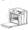
Figure 1 - is the front perspective view of the cooking device. -
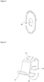
Figure 2 - is the front perspective view of the first receiving region. -
Figure 3 - is the front perspective view of the second receiving region. -
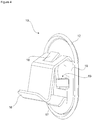
Figure 4 - is the sideways perspective view of the first receiving member group. -
Figure 5 - is the top perspective view of the second receiving member group. -
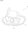
Figure 6 - is the front perspective view of the first receiving member group and the second receiving member group placed onto the side wall. - The elements illustrated in the figures are numbered as follows:
- 1. Cooking device
- 2. Cooking chamber
- 3. Casing
- 4. Side wall
- 5. Rack support
- 6. Guide wire
- 7. Connection wire
- 8. First carrier member
- 9. Second carrier member
- 10. First receiving member group
- 11. Second receiving member group
- 12. First receiving region
- 13. Second receiving region
- 14. Third receiving region
- 15. Fourth receiving region
- 16. Guiding member
- 17. Fixing member
- 18. Claw
- 19. Lateral surface
- The cooking device (1) comprises a cooking chamber (2) wherein the foodstuffs to be cooked are placed; and a casing (3) in the form of a box with the front side open which has a plurality of walls(4) enclosing the cooking chamber (2). A plurality of rack supports (5) are provided on the side walls (4) so as to support one or more than one tray. The rack support (5) has one or more than one guide wire (6) oppositely at different levels predetermined by the producer. The guide wires (6) positioned parallel to each other are fixed to each other by means of at least one connection wire (7) which is perpendicular to the guide wires (6). The rack support (5) comprises a first carrier member (8) and a second carrier member (9) provided on the guide wire (6). The first carrier member (8) extends towards the front section of the guide wire (6). The second carrier member (9) extends towards the rear section of the guide wire (6). The first carrier member (8) is fixed onto the side wall (4) by means of at least one first receiving member group (10) while the second carrier member (9) is fixed onto the side wall (4) by means of at least one second receiving member group (11).
- The rack support (5) of the present invention comprises a first receiving region (12) which enables the first carrier member (8) to be inserted into the first receiving member group (10) in the direction of entry. After being inserted, the first carrier member (8) moves in a second receiving region (13). The second carrier member (9) is inserted through a third receiving region (14) provided on the second receiving member group (12) so as to be at an angle with respect to the direction of entry of the first carrier member (8). The second receiving member group (11) comprises a fourth receiving region (15) wherein the second carrier member (9) can move after being inserted into the third receiving region (14). During the mounting of the rack support (5) onto the side wall (4), preferably first the second carrier member (9) is placed onto the second receiving member group (11). After the second carrier member (9) is placed onto the side wall (4), the first carrier member (8) is placed onto the side wall (4) by means of the first receiving member group (10).
- In an embodiment of the present invention, the first receiving member group (10) comprises a guiding member (16) which is positioned at the second receiving region (13) and which enables the first carrier member (8) to move in the second receiving region (13) so as to be at an angle with respect to the direction of entry into the first receiving region (12). Thus, the first carrier member (8) and the second carrier member (9) can easily move on the first receiving member group (10) and the second receiving member group (11).
- In another embodiment of the present invention, the first receiving member group (11) comprises at least one fixing member (17) which enables the first carrier member (8) to be fixed onto the first receiving member group (10). Thus, the movement of the first carrier member (8) on the second receiving region (13) is limited, ensuring a connection with the first receiving member group (10). The fixing member (17) is disposed on the second receiving region (13).
- In another embodiment of the present invention, the first receiving member group (10) comprises at least one claw (18) which extends from the second receiving region (13) towards the first receiving region (12). By means of the claw (18), the first carrier member (8) is prevented from being detached from the first receiving member group (10). The claw (18) is provided on the guiding member (16) and/or the lateral surfaces (19) of the second receiving region (13). By means of the claws (18) provided on the lateral surfaces (19), the rack support (5) is securely attached onto the side wall, preventing energy loss.
- In another embodiment of the present invention, the rack support (5) comprises the first receiving region (12) and the second receiving region (13) which are in the form of a window. Thus, the first carrier member (8) is surrounded by the first receiving member group (10) while the second carrier member (9) is surrounded by the second receiving member group (11).
- In another embodiment of the present invention, the rack support (5) comprises the second receiving member group (11) which is obtained by rotating the first receiving member group (10) 90 degrees and which enables the second carrier member (9) to be placed onto the side wall (4).
- In another embodiment of the present invention, the rack support (5) comprises the first receiving member group (10) and the second receiving member group (11) which have identical structures.
- By means of the present invention, the rack support (5) is fixed onto the side wall by placing the first carrier member (8) onto the first receiving member group (10) and the second carrier member (9) onto the second receiving member group (11).
Claims (7)
- A cooking device (1) comprising a cooking chamber (2) wherein the foodstuffs to be cooked are placed; a casing (3) in the form of a box with the front side open which has a plurality of walls(4) enclosing the cooking chamber (2); two rack supports (5) having one or more than one guide wire (6) which are oppositely disposed on the walls (4) and arranged at different levels predetermined by the producer and at least one connection wire (7) which enable the guide wires (6) to be fixed to each other and which extends perpendicularly to the guide wires (6); a first carrier member (8) and a second carrier member (9) which are provided on the guide wire (6); a first receiving member group (10) which enables the first carrier member (8) to be placed onto the side wall (4) and a second receiving member group (11) which enables the second carrier member (9) to be placed onto the side wall (4), characterized by - a first receiving region (12) which is arranged on the first receiving member group (10) and which enables the first carrier member (8) to be inserted in the direction of entry, and a second receiving region (13) wherein the first carrier member (8) moves after being inserted, and - a third receiving region (14) which is arranged on the second receiving member group (11) and which enables the second carrier member (9) to be inserted so as to be at an angle with respect to the direction of entry of the first carrier member (8), and a fourth receiving region (15) wherein the second carrier member (9) moves after being inserted.
- A cooking device (1) as in Claim 1, characterized by a guiding member (16) which is positioned at the second receiving region (13) and which enables the first carrier member (8) to move in the second receiving region (13) so as to be at an angle with respect to the direction of entry into the first receiving region (12).
- A cooking device (1) as in any one of the above claims, characterized by at least one fixing member (17) which is positioned at the second receiving region (13) and which enables the first carrier member (8) to be fixed onto the first receiving member group (10) by engagement.
- A cooking device (1) as in any one of the above claims, characterized by at least one claw (18) which extends on the guiding member (16) from the second receiving region (13) towards the first receiving region (12) and which prevents the first carrier member (8) from detaching from the first receiving member group (10).
- A cooking device (1) as in any one of the above claims, characterized by the first receiving region (12) and the second receiving region (13) which are in the form of a window.
- A cooking device (1) as in any one of the above claims, characterized by the second receiving member group (11) which is obtained by rotating the first receiving member group (10) 90 degrees and which enables the second carrier member (9) to be placed onto the side wall (4).
- A cooking device (1) as in any one of the above claims, characterized by the first receiving member group (10) and the second receiving member group (11) which have identical structures.
Applications Claiming Priority (1)
| Application Number | Priority Date | Filing Date | Title |
|---|---|---|---|
| TR2019/14393A TR201914393A2 (en) | 2019-09-23 | 2019-09-23 | A COOKING DEVICE |
Publications (1)
| Publication Number | Publication Date |
|---|---|
| EP3795909A1 true EP3795909A1 (en) | 2021-03-24 |
Family
ID=72292384
Family Applications (1)
| Application Number | Title | Priority Date | Filing Date |
|---|---|---|---|
| EP20193639.0A Withdrawn EP3795909A1 (en) | 2019-09-23 | 2020-08-31 | A cooking device |
Country Status (2)
| Country | Link |
|---|---|
| EP (1) | EP3795909A1 (en) |
| TR (1) | TR201914393A2 (en) |
Citations (6)
| Publication number | Priority date | Publication date | Assignee | Title |
|---|---|---|---|---|
| US20050172830A1 (en) * | 2002-09-03 | 2005-08-11 | Bsh Bosch Und Siemens Hausgerate Gmbh | Support unit, particularly for a cooking device |
| EP1840473A2 (en) | 2006-03-31 | 2007-10-03 | Miele & Cie. KG | Telescopic device for attachment to a supporting frame in the operational area of a domestic appliance |
| EP2615312A1 (en) * | 2012-01-11 | 2013-07-17 | BSH Bosch und Siemens Hausgeräte GmbH | Bearing bush, designed for the bearing of a component of a domestic appliance, and domestic appliance with such a bearing bush |
| DE102012217358A1 (en) * | 2012-09-26 | 2014-03-27 | BSH Bosch und Siemens Hausgeräte GmbH | Bearing bush, which is designed for storing a household appliance component on a household appliance component, and household appliance with such a bushing |
| EP2843316A1 (en) | 2013-08-05 | 2015-03-04 | Laag S.r.l. | Suspension device for an apparatus, in particular a baking oven |
| EP3211324A1 (en) * | 2016-02-23 | 2017-08-30 | BSH Hausgeräte GmbH | Bearing bush for a household appliance with a spring element, comprising a cover for covering an insertion opening, assembly and household appliance |
-
2019
- 2019-09-23 TR TR2019/14393A patent/TR201914393A2/en unknown
-
2020
- 2020-08-31 EP EP20193639.0A patent/EP3795909A1/en not_active Withdrawn
Patent Citations (6)
| Publication number | Priority date | Publication date | Assignee | Title |
|---|---|---|---|---|
| US20050172830A1 (en) * | 2002-09-03 | 2005-08-11 | Bsh Bosch Und Siemens Hausgerate Gmbh | Support unit, particularly for a cooking device |
| EP1840473A2 (en) | 2006-03-31 | 2007-10-03 | Miele & Cie. KG | Telescopic device for attachment to a supporting frame in the operational area of a domestic appliance |
| EP2615312A1 (en) * | 2012-01-11 | 2013-07-17 | BSH Bosch und Siemens Hausgeräte GmbH | Bearing bush, designed for the bearing of a component of a domestic appliance, and domestic appliance with such a bearing bush |
| DE102012217358A1 (en) * | 2012-09-26 | 2014-03-27 | BSH Bosch und Siemens Hausgeräte GmbH | Bearing bush, which is designed for storing a household appliance component on a household appliance component, and household appliance with such a bushing |
| EP2843316A1 (en) | 2013-08-05 | 2015-03-04 | Laag S.r.l. | Suspension device for an apparatus, in particular a baking oven |
| EP3211324A1 (en) * | 2016-02-23 | 2017-08-30 | BSH Hausgeräte GmbH | Bearing bush for a household appliance with a spring element, comprising a cover for covering an insertion opening, assembly and household appliance |
Also Published As
| Publication number | Publication date |
|---|---|
| TR201914393A2 (en) | 2021-04-21 |
Similar Documents
| Publication | Publication Date | Title |
|---|---|---|
| EP2032005B1 (en) | Rack assembly | |
| US9622296B2 (en) | Induction cooking hob | |
| EP3494345B1 (en) | Cooking appliance with improved side wire racks | |
| WO2013074443A1 (en) | Oven accessory with removable inserts | |
| US8826898B2 (en) | Metal rack for an oven appliance | |
| AU2014210119A1 (en) | An induction module for an induction cooking hob | |
| US20130118475A1 (en) | Metal rack for an oven appliance | |
| EP2748536A1 (en) | An oven comprising a movable support | |
| EP3149408B1 (en) | Oven | |
| US20130292369A1 (en) | Home appliance with unitary broil element mount and reflector | |
| EP2390585B1 (en) | An oven cavity for a cooking oven | |
| EP2469190A1 (en) | A cooking hob including an upper part and a base part | |
| EP3155160B1 (en) | A household appliance comprising a printed circuit board | |
| WO2018188722A1 (en) | Cooking appliance with improved assemblage | |
| EP3413689B1 (en) | Connection element for connecting a heating energy generating element to a carrier element of a cooking hob | |
| AU781401B2 (en) | Shell structure for a heating appliance, and method of manufacturing heating appliance including same | |
| EP2370738B1 (en) | An oven comprising a door | |
| WO2020099018A1 (en) | An oven comprising a drawer | |
| WO2014072133A1 (en) | Oven comprising support unit | |
| WO2019129401A1 (en) | An oven comprising shelf support made of wire | |
| WO2019129441A1 (en) | An oven comprising a connection element | |
| WO2019129402A1 (en) | An oven comprising shelf support made of wire | |
| EP3800401B1 (en) | A cooking device | |
| EP3789706A1 (en) | A mounting member for the mounting of the decorative panel to the built-in household appliance | |
| EP1985931B1 (en) | Cooking hob |
Legal Events
| Date | Code | Title | Description |
|---|---|---|---|
| PUAI | Public reference made under article 153(3) epc to a published international application that has entered the european phase |
Free format text: ORIGINAL CODE: 0009012 |
|
| STAA | Information on the status of an ep patent application or granted ep patent |
Free format text: STATUS: REQUEST FOR EXAMINATION WAS MADE |
|
| 17P | Request for examination filed |
Effective date: 20200831 |
|
| AK | Designated contracting states |
Kind code of ref document: A1 Designated state(s): AL AT BE BG CH CY CZ DE DK EE ES FI FR GB GR HR HU IE IS IT LI LT LU LV MC MK MT NL NO PL PT RO RS SE SI SK SM TR |
|
| AX | Request for extension of the european patent |
Extension state: BA ME |
|
| STAA | Information on the status of an ep patent application or granted ep patent |
Free format text: STATUS: THE APPLICATION IS DEEMED TO BE WITHDRAWN |
|
| 18D | Application deemed to be withdrawn |
Effective date: 20210925 |