EP3149408B1 - Oven - Google Patents
Oven Download PDFInfo
- Publication number
- EP3149408B1 EP3149408B1 EP15800427.5A EP15800427A EP3149408B1 EP 3149408 B1 EP3149408 B1 EP 3149408B1 EP 15800427 A EP15800427 A EP 15800427A EP 3149408 B1 EP3149408 B1 EP 3149408B1
- Authority
- EP
- European Patent Office
- Prior art keywords
- rail
- oven
- guide rails
- cooking compartment
- unit
- Prior art date
- Legal status (The legal status is an assumption and is not a legal conclusion. Google has not performed a legal analysis and makes no representation as to the accuracy of the status listed.)
- Active
Links
- 238000010411 cooking Methods 0.000 claims description 61
- 238000009434 installation Methods 0.000 claims description 32
- 238000003780 insertion Methods 0.000 claims description 28
- 230000037431 insertion Effects 0.000 claims description 28
- 239000000126 substance Substances 0.000 description 14
- 238000005452 bending Methods 0.000 description 1
- 238000004140 cleaning Methods 0.000 description 1
- 238000004939 coking Methods 0.000 description 1
- 230000000694 effects Effects 0.000 description 1
- 238000000034 method Methods 0.000 description 1
- XLYOFNOQVPJJNP-UHFFFAOYSA-N water Substances O XLYOFNOQVPJJNP-UHFFFAOYSA-N 0.000 description 1
Images


Classifications
-
- F—MECHANICAL ENGINEERING; LIGHTING; HEATING; WEAPONS; BLASTING
- F24—HEATING; RANGES; VENTILATING
- F24C—DOMESTIC STOVES OR RANGES ; DETAILS OF DOMESTIC STOVES OR RANGES, OF GENERAL APPLICATION
- F24C7/00—Stoves or ranges heated by electric energy
- F24C7/04—Stoves or ranges heated by electric energy with heat radiated directly from the heating element
-
- F—MECHANICAL ENGINEERING; LIGHTING; HEATING; WEAPONS; BLASTING
- F24—HEATING; RANGES; VENTILATING
- F24C—DOMESTIC STOVES OR RANGES ; DETAILS OF DOMESTIC STOVES OR RANGES, OF GENERAL APPLICATION
- F24C15/00—Details
- F24C15/16—Shelves, racks or trays inside ovens; Supports therefor
- F24C15/168—Shelves, racks or trays inside ovens; Supports therefor with telescopic rail systems
Definitions
- Embodiments of the present disclosure relate to an oven, and more particularly, an oven having guide rails.
- An oven is an apparatus configured to seal, heat, and cook food substance, and in general may be divided into an electric-type oven, a gas-type oven, and an electronic-type oven according to a heat source thereof.
- the electric-type oven is configured to use an electric heater as a heat source, as the gas-type oven and the electronic-type oven are configured to use a heat by gas and by a frictional heat of water molecules by high frequency, respectively.
- a cooking compartment configured to heat food substance may be provided at an inside the oven.
- At least one shelf member configured to settle food substance may be disposed at the cooking compartment.
- the shelf member may be installed as to be withdrawn in a sliding manner toward a front surface for convenience of a user. At this time, the shelf member may be withdrawn by use of a guide member.
- the guide member may include a pair of rails movably installed at side surfaces of the cooking compartment.
- the each of the pair of rails is installed at the each side surface of the coking compartment, thereby may be separately moved.
- the each rail may be separately disposed, and an inconvenience may be present.
- an oven in accordance with one aspect of the present disclosure, includes a cooking compartment, a shelf member, and a fixing wire.
- the cooking compartment comprises an upper surface, a lower surface and side panels.
- the shelf member is disposed at an inside the cooking compartment and allowing food substance to be mounted thereon.
- a plurality of guide rails are installed such that the shelf member is withdrawn from the cooking compartment.
- the plurality of guide rails each compromise a first rail and a second rail.
- the fixing wire is installed as to connect the plurality of guide rails and having a plurality of contact units configured to make contact with the plurality of guide rails, respectively.
- the at least one contact unit is formed while provided with a step.
- the at least one contact unit includes a plurality of mounting units and an insertion unit provided in between the plurality of mounting units.
- the insertion unit is further protruded than the mounting units with respect to the closest of the side.
- the insertion unit is installed such that at least one portion thereof is inserted in between the first rail and the second rail.
- Each of the guide rails includes a plurality of first brackets at which the fixing wire is mounted.
- the at least one contact unit includes a plurality of mounting units mounted at the plurality of first brackets and an insertion unit provided in between the plurality of mounting units, and the plurality of mounting units and the insertion unit are formed while provided with a step.
- the plurality of mounting units each may be mounted at each of the plurality of first brackets in a downward direction, and the insertion unit may be disposed such that at least one portion of each of the guide rails is positioned at an upper portion of the insertion unit.
- the plurality of first brackets each may be disposed at one side surface of each of the guide rails.
- the fixing wire may be provided in the shape of a closed loop as to connect the plurality of guide rails.
- the fixing wire may be positioned in between the plurality of guide rails.
- the fixing wire may include a handle unit provided as to be grabbed.
- the oven may further include an installation member at which the plurality of guide rails is mounted.
- the plurality of guide rails may each include a first rail connected by the fixing wire, and a second rail mounted at the installation member.
- the first rail may include a first bracket at which the fixing wire is mounted, and the second rail may include a second bracket coupled to the installation member.
- the first rail may include at least one safety member configured to fix the shelf member to one direction.
- the installation member may be mounted at an inner side wall of the cooking compartment, as to support the shelf member and the guide rails.
- the cooking compartment may include at least one supporting member being installed at an inner side wall of the cooking compartment, such that the installation member is mounted at the inner side wall of the cooking compartment,
- An inner side wall of the cooking compartment may include at least one concave surface such that the installation member is mounted at the inner side wall of the cooking compartment.
- an oven in accordance with another aspect of the present disclosure, includes a shelf member, an installation member and a guide member.
- the shelf member may allow food substance to be placed.
- the installation member may be detachably mounted at an inside the cooking compartment.
- the guide member may have a plurality of guide rails disposed in between the shelf member and the installation member.
- the guide member may also have a fixing wire connecting the plurality of guide rails.
- the plurality of guide rails may each include a first rail at which the shelf member is mounted, and a second rail coupled to the installation member, and the fixing wire may be installed as to connect each first rail.
- the first rail may include a plurality of first brackets at which the fixing wire is mounted.
- the fixing wire may include a plurality of mounting units being mounted at the plurality of first brackets and an insertion unit provided in between the plurality of mounting units.
- the plurality of mounting units and the insertion unit may be formed while provided with a step.
- the plurality of guide rails may each include a first rail being connected by the fixing wire, and the first rail may include an upper surface unit at which the shelf member is mounted.
- the first rail may include a side surface unit provided with one side thereof connected to the upper surface unit while the other side thereof is connected to a lower surface unit, and a first bracket at which the fixing wire is mounted may be installed at the side surface unit.
- At least one portion of the fixing wire may be positioned at a lower portion of the lower surface unit.
- an oven in accordance with another aspect of the present disclosure, includes a shelf member, a pair of guide rails, and a fixing wire.
- the shelf member may be disposed at an inside a cooking compartment.
- the pair of guide rails may be installed as to move the shelf member, and each having a plurality of rails.
- the fixing wire may be disposed as to connect the pair of guide rails, and at least one portion of the fixing wire may be disposed in between the plurality of rails.
- the plurality of rails may include a first rail movably installed and a second rail fixedly installed.
- the fixing wire may be provided with at least one portion thereof disposed in between the first rail and the second rail.
- the pair of guide rails may each include a plurality of first brackets allowing the fixing wire to be mounted thereon.
- the fixing wire may include a plurality of mounting units being mounted at the plurality of first brackets and an insertion unit provided in between the plurality of mounting units.
- the insertion unit may be installed such that at least one portion thereof is inserted into in between the plurality of rails.
- the pair of guide rails may each include side surface units provided as to face each other, and at least one portion of the fixing wire may be mounted at the side surface units.
- the pair of guide rails may each include a lower surface unit being bent from the side surface unit toward a different direction with respect to each other, and at least one portion of the fixing wire may be positioned at a lower portion of the lower surface unit.
- the left and right movements of guide rails can be stabilized by use of a fixing wire stably coupled to the guide rails.
- a user can be conveniently able to clean a withdrawal unit as the guide rails and the fixing wire are coupled so as to be easily.
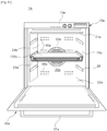
- FIG. 1 and FIG. 2 are drawings illustrating an oven 1 in accordance with one embodiment of the present disclosure.
- FIG. 1 is a drawing illustrating the oven 1 from a front direction in a state of a door 30 thereof open
- FIG. 2 is a drawing illustrating a cross-sectional view from a side of the oven 1 in a state of the door 30 closed.
- a withdrawal unit 100 is schematically illustrated on FIG. 1 and FIG. 2 .
- the oven 1 includes a casing 10 and a cooking compartment 20 provided at an inside the casing 10.
- the cooking compartment 20 is provided as to have a front opening unit, and the oven 1 may include the door 30 as to open/close the front opening unit of the cooking compartment 20.
- the door 30 may be rotatabley coupled to one side of the casing 10 as to form an exterior appearance of the casing 10.
- the cooking compartment 20 is referred to as a cooking space in which food substance is cooked, and is structured by an upper surface panel 21, a lower surface panel 22, side surface panels 23, and a rear surface panel 24.
- Various parts structuring the oven 1 may be disposed at a space provided in between the cooking compartment 20 and the casing 10.
- a fan cover 40 may be coupled to an outer side of the rear surface panel 24.
- a convection fan 41 configured to circulate air through the cooking compartment 20 may be provided in between the rear surface panel 24 and the fan cover 40.
- At least one electrical heater 42 is installed at the convection fan 41, and a driving motor 43 connected to the convection fan 41 may be installed in between the fan cover 40 and th casing 10.
- the rear surface panel 24 may include a plurality of inlet holes 25 formed such that the air at an inside the cooking compartment 20 may be moved to the convection fan 41.
- the plurality of inlet holes 25 may be formed at the surroundings of a central portion of the rear surface panel 24 which faces the convection fan 41.
- the rear surface panel 24 may include a plurality of outlet holes 26 formed such that heat may be moved to an inside the cooking compartment 20.
- an insulating member 44 may be disposed at outer sides of the upper surface panel 21, the lower surface panel 22, the side surface panels 23, and the fan cover 40 forming the cooking compartment 20.
- a control panel 12 configured to control the driving of the oven 1 may be installed at an upper portion of the casing 10. As for a user to open/close the cooking compartment 20, a lower portion of the door 30 may be installed while hinge-coupled to a lower end portion of the casing 10. A handle 37 may be attached to an upper portion of the door 30 such that a user may be able to grab and rotate the door 30.
- the at least one withdrawal unit 100 provided such that food substance is placed may be disposed at an inside the cooking compartment 20.
- the withdrawal unit 100 may be installed while mounted at an inner wall of the cooking compartment 20.
- the both side surface panels 23 may include at least one supporting member 27.
- the supporting member 27 may be fixed while spaced apart with respect to each other by a predetermined distance at the each of the side surface panels 23. That is, the both side surface panels 23 are provided in the shape of plane panels, and the supporting member 27 may be able to support the withdrawal unit 100 as the supporting member 27 is fixed at the both side surface panels 23.
- the supporting member 27 may be provided in pairs as to restrain the withdrawal unit 100 toward vertical directions.
- the supporting member 27 may be provided in a plurality of pairs.
- the cooking compartment 20 is sealed by rotating the door 30 after the food substance is placed at the withdrawal unit 100 supported by the supporting member 27. Then, the electrical heater 42 is heated as the control panel 12 is manipulated, and the convection fan 41 is rotated by the driving motor 43. The air at an inside the cooking compartment 20 is inlet through the inlet holes 25, and then is heated by the electrical heater 42. The inlet air after being heated is supplied to the cooking compartment 20 through the outlet holes 26. The heated air being supplied through the outlet holes 26 may be able to cook the food substance while circulating the inside the cooking compartment 20.
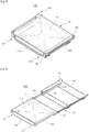
- FIG. 3 and FIG. 4 are drawings illustrating the withdrawal unit 100 of the oven 1 in accordance with one embodiment of the present disclosure
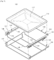
- FIG. 5 is an exploded drawing illustrating the withdrawal unit 100 of the oven 1 in accordance with one embodiment of the present disclosure.
- the withdrawal unit 100 includes a shelf member 110, and a guide member 120 at which the shelf member 110 is mounted.
- the withdrawal unit 100 may include an installation member 150 mounted at an inside the cooking compartment 20.
- the shelf member 110 is disposed at an inside the cooking compartment 20 such that food substance may be mounted.
- the shelf member 110 may be provided in various shapes such that food substance may be mounted.
- the shelf member 110 may include a bottom surface 112 provided in the shape of a plane panel such that various sizes of food substance may be mounted.
- the shelf member 110 may be installed such that the shelf member 110 may be moved toward a front of the cooking compartment 20 for the convenience of a user.
- the installation member 150 may be detachably mounted at an inside the cooking compartment 20.
- the installation member 150 may be able to support the shelf member 110 and the guide member 120 while mounted at an inner wall of the cooking compartment 20.
- the installation member 150 may be mounted at the side surface panels 23 by use of the supporting member 27.
- the installation member 150 may include a supporting unit 152 provided as to be inserted into in between the pair of supporting members 27 that are disposed while being spaced with respect to each other.
- the supporting unit 152 may be provided at both sides of the installation member 150 while corresponding to the supporting members 27 provided at the both side surface panels 23.
- the supporting unit 152 may be provided in a protruded shape toward the both side surface panels 23 as to be disposed in between the pair of supporting members 27.
- the guide member 120 is installed such that the shelf member 110 may be withdrawn from the cooking compartment 20.
- the guide member 120 includes a plurality of guide rails 130, and a fixing wire 140 connecting the plurality of guide rails 130.
- the plurality of guide rails 130 are installed so that the shelf member 110 may be moved.
- the guide rail 130 may be formed in various shapes so that the shelf member 110 may be moved.
- the plurality of guide rails 130 are provided in a pair of guide rails 130 supporting both sides of the shelf member 110.
- the pair of guide rails 130 supporting the shelf member 110 may be mounted at the installation member 150. That is, the pair of guide rails 130 may be disposed in between the shelf member 110 and the installation member 150.
- the pair of guide rails 130 each includes a plurality of rails.
- the plurality of rails may include a first rail 132 at which the shelf member 110 is mounted, and a second rail 134 being mounted at the installation member 150.
- the first rail 132 may be installed such that the first rail 132 may be moved along with the shelf member 110.
- the second rail 134 may be installed such that the second rail 134 may be fixed along with the installation member 150 being mounted at an inner wall of the cooking compartment 20.
- the first rail 132 includes a first bracket 131 at which the fixing wire 140 is mounted.
- the second rail 134 may include a second bracket 135 coupled to the installation member 150.
- the first bracket 131 and the second bracket 135 each may be provided in a plurality of units.
- the first rail 132 may include at least one safety member 133 configured to fix the shelf member 110 toward one direction.
- the safety member 133 may be provided at both ends of the first rail 132 in a protruded shape toward an upper side.
- the shelf member 110 is mounted at an upper portion of the first rail 132, and the relative movements toward forward/backward direction with respect to the first rail 132 may be restrained by the safety member 133.
- the plurality of rails may include a connecting rail 136 disposed in between the first rail 132 and the second rail 134.
- the connecting rail 136 is capable of supplying an extra length at which the shelf member 110 may be moved toward a front of the cooking compartment 20.
- a ball bearing (not shown) may be provided in between the first rail 132, and the connecting rail 136, as well as in between the connecting rail 136 and the second rail 134.
- the fixing wire 140 is positioned in between the pair of guide rails 130 as to connect the guide rails 130.
- the fixing wire 140 is provided as to connect the first rails 132 each disposed at the each of the pair of guide rails 130.
- the fixing wire 140 may include a handle unit 148 provided such that a user may be able to grip.
- the handle unit 148 may be provided toward a front of the cooking compartment 20.
- a user may be able to withdraw the withdrawal unit 100 disposed as illustrated on FIG. 3 toward a front while applying an outside force by gripping the handle unit 148.
- the shelf member 110 is moved toward a front as illustrated on FIG. 4 , and a user may be able to withdraw/deposit food substance from/to the shelf member 110.
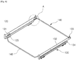
- FIG. 6 and FIG. 7 are drawings illustrating the guide member 120 of the oven 1 in accordance with one embodiment of the present disclosure
- FIG. 8 is an enlarged drawing illustrating an 'A' portion of FIG. 6
- FIG. 7 is a drawing illustrating an upper surface of the guide member 120, and for the purpose of descriptions, one side of FIG. 8 is cut out and illustrated.
- FIG. 9 is a drawing illustrating a cross section of the guide member 120 of the oven 1 in accordance with one embodiment of the present disclosure
- FIG. 10 is an exploded drawing illustrating the guide member 120 of the oven 1 in accordance with one embodiment of the present disclosure.
- the guide member 120 includes the guide rail 130 and the fixing wire 140, and the guide rail 130 and the fixing wire 140 may be detachably coupled to each other.
- the fixing wire 140 may be installed as to connect the guide rails 130.
- the fixing wire 140 may be provided in the shape of a closed loop as to connect the pair of guide rails 130.
- the fixing wire 140 may be provided in the shape of a rectangular frame that is formed by bending.
- the fixing wire 140 includes a plurality of contact units 142 each making contact with the each of the plurality of guide rails 130.
- the contact unit 142 is provided at both sides by corresponding to the pair of guide rails 130.
- the contact unit 142 may be referred to as one surface of the fixing wire 140.
- the each contact unit 142 is formed while provided with a step.
- the each contact unit 142 includes a plurality of mounting units 146 mounted at the first bracket 131, and an insertion unit 144 provided in between the plurality of mounting units 146. At this time, the plurality of mounting units 146 and the insertion unit 144 are formed while provided with a step.
- the insertion unit 144 is provided such that the insertion unit 144 is further protruded then the mounting unit 146 with respect to the guide rail 130.
- the insertion unit 144 is installed such that at least one portion thereof is inserted into in between the guide rail 130. That is, the fixing wire 140 is provided with at least one portion thereof disposed in between the first rail 132 and the second rail 134.
- the first bracket 131 may be disposed at one side surface of the guide rail 130.
- the mounting unit 146 may be mounted at the first bracket from an upper portion to a lower portion. As illustrated on FIG. 8 , one side of the first bracket 131 is fixed to one side surface of the first rail 132, and the other side of the first bracket 131 may be extended as to accommodate the mounting unit 146.
- the first bracket 131 and the mounting unit 146 correspondingly provided with respect to the first bracket 131 may be provided in a plurality of units at the pair of guide rails 130.
- the first rail 132 may be formed in a bent manner as to be provided with an accommodating space at an inside thereof.
- the connecting rail 136, etc. may be disposed at the accommodating space, and the first rail 132 may be provided while wrapping around at least one portion of the connecting rail 136, etc.
- a surface provided at an upper portion of the first rail 132 such that the shelf member 110 may be mounted is referred to as an upper surface unit 137.
- a surface at which the first bracket 131 is positioned at the first rail 132 is referred to as a side surface unit 138.
- the side surface unit 138 is provided with one side thereof connected to the upper surface unit 137, and the other side of the side surface unit 138 may be connected to a lower surface unit 139.
- the lower surface unit 139 may be provided in a bent manner toward the accommodating space from the side surface unit 138.
- the mounting unit 146 is restrained toward a lower direction by the first bracket 131, and the insertion unit 144 may be restrained toward an upper direction by the side surface unit 138 and the lower surface unit 139.
- the contact unit 142 may be coupled to the guide rail 130 while restrained toward vertical directions, and the fixing wire 140 may be able to firmly connect the pair of guide rails 130.
- the second rail 134 as well may be provided while provided with an identical cross-sectional surface with respect to the first rail 132.
- the insertion unit 144 may be provided with at least one portion thereof disposed in between the first rail 132 and the second rail 134.
- the insertion unit 144 may be disposed while making contact with the first rail 132 so that the insertion unit 144 may be able to be moved along with the first rail 132.
- the insertion unit 144 may be disposed not to make contact with the second rail 134.
- FIG. 11 is a drawing illustrating an oven 1a in accordance with another embodiment of the present disclosure.
- FIG. 11 is a drawing illustrating an oven 1a in accordance with another embodiment of the present disclosure.
- the oven 1a may include a casing 10a, a cooking compartment 20a provided at an inside the casing 10a, and a door 30a provided as to open/close the cooking compartment 20a.
- a handle 37a may be attached to the door 30a.
- the cooking compartment 20a may be structured by an upper surface panel 21a, a lower surface panel 22a, side surface panels 23a, and a rear surface panel 24a.
- the rear surface panel 24a may include a plurality of inlet holes 25a and a plurality of outlet holes 26a.
- a control panel 12a may be installed at the casing 10a.
- At least one withdrawal unit 100a is disposed at an inside the cooking compartment 20a, and the withdrawal unit 100a may be installed while mounted at an inner surface of the cooking compartment 20a.
- the both side surface panels 23a may include a concavo-convex structure.
- the concavo-convex structure may include a plurality of concave surfaces 28 each spaced apart by a predetermined distance at the side surface panels 23a. That is, the side surface panels 23a are not provided in a plane manner, and the side surface panels 23a may be directly able to support the withdrawal unit 100a.
- the convex surfaces 28 each may be disposed at a predetermined position so that the withdrawal unit 100a may be installed at a height that is needed for a user.
- FIG. 12 is a drawing illustrating the withdrawal unit 100a of the oven 1a in accordance with another embodiment of the present disclosure
- FIG. 13 is an exploded drawing illustrating the withdrawal unit 100a of the oven 1a in accordance with another embodiment of the present disclosure.
- the withdrawal unit 100a may include a shelf member 110a, a guide member 120a, and an installation member 150a. As illustrated on FIG. 12 , the shelf member 110a may include a bottom surface 112a provided by use of wires arranged toward one direction.
- the installation member 150a may be mounted at the concave surface 28 provided at the side surface panel 23a.
- the installation member 150a may include a supporting unit 152a provided as to be inserted into the concave surface 28.
- the supporting units 152a may be provided at the both sides of the installation member 150a while corresponding to the concave surfaces 28 that are provided at the both side surface panels 23a.
- the supporting units 152a may be provided in a protruded shape toward the both side surface panels 23a as to be mounted at the concave surfaces 28.
- the guide member 120a may include a pair of guide rails 130a and a fixing wire 140a.
- the pair of guide rails 130a each may include a plurality of rails.
- the plurality of rails may include a first rail 132a at which the shelf member 110a is mounted, and a second rail 134a being mounted at the installation member 150a.
- a ball bearing (not shown) may be provided in between the first rail 132a and the second rail 134a.
- the first rail 132a includes a first bracket 131a and a safety member 133a
- the second rail 134a may include a second bracket 135a.
- the fixing wire 140a may include a plurality of contact units 142a and a handle unit 148a.
- the each contact unit 142a may include a plurality of mounting units 146a, and an insertion unit 144a provided in between the plurality of mounting units 146a.
- the plurality of mounting units 146a and the insertion unit 144a may be formed while provided with a step.
Description
- Embodiments of the present disclosure relate to an oven, and more particularly, an oven having guide rails.
- An oven is an apparatus configured to seal, heat, and cook food substance, and in general may be divided into an electric-type oven, a gas-type oven, and an electronic-type oven according to a heat source thereof. The electric-type oven is configured to use an electric heater as a heat source, as the gas-type oven and the electronic-type oven are configured to use a heat by gas and by a frictional heat of water molecules by high frequency, respectively.
- A cooking compartment configured to heat food substance may be provided at an inside the oven. At least one shelf member configured to settle food substance may be disposed at the cooking compartment. The shelf member may be installed as to be withdrawn in a sliding manner toward a front surface for convenience of a user. At this time, the shelf member may be withdrawn by use of a guide member.
- In general, the guide member may include a pair of rails movably installed at side surfaces of the cooking compartment. The each of the pair of rails is installed at the each side surface of the coking compartment, thereby may be separately moved. Thus, in a case when a user withdraws and settles the shelf member from the rails, the each rail may be separately disposed, and an inconvenience may be present.
- There is an oven using a fixing wire as to connect one pair of rails. However, the fixing wire is press-fitted to a bracket provided at the rail, cleaning the fixing wire by separating may be difficult. In addition, only the portion of the fixing wire coupled by the bracket is fixed, and thus the fixing wire may not be able to stably connect the rail.
-
DE 101 02 589A1 ,JP 2011-112301 A US 2013/0118471 A1 ,US 2005/0217501 A1 andES 2 392 291 A1 - It is an aspect of the present disclosure to provide an oven having guide rails configured to stably move when withdrawing a shelf member.
- It is another aspect of the present disclosure to provide an oven provided with guide rails and a fixing wire firmly inserted to each other and fixedly coupled to each other by a step structure of the fixing wire.
- Additional aspects of the disclosure will be set forth in part in the description which follows.
- In accordance with one aspect of the present disclosure, an oven includes a cooking compartment, a shelf member, and a fixing wire. The cooking compartment comprises an upper surface, a lower surface and side panels. The shelf member is disposed at an inside the cooking compartment and allowing food substance to be mounted thereon. A plurality of guide rails are installed such that the shelf member is withdrawn from the cooking compartment. The plurality of guide rails each compromise a first rail and a second rail. The fixing wire is installed as to connect the plurality of guide rails and having a plurality of contact units configured to make contact with the plurality of guide rails, respectively. The at least one contact unit is formed while provided with a step. The at least one contact unit includes a plurality of mounting units and an insertion unit provided in between the plurality of mounting units. The insertion unit is further protruded than the mounting units with respect to the closest of the side. The insertion unit is installed such that at least one portion thereof is inserted in between the first rail and the second rail.
- Each of the guide rails includes a plurality of first brackets at which the fixing wire is mounted.
- The at least one contact unit includes a plurality of mounting units mounted at the plurality of first brackets and an insertion unit provided in between the plurality of mounting units, and the plurality of mounting units and the insertion unit are formed while provided with a step.
- The plurality of mounting units each may be mounted at each of the plurality of first brackets in a downward direction, and the insertion unit may be disposed such that at least one portion of each of the guide rails is positioned at an upper portion of the insertion unit.
- The plurality of first brackets each may be disposed at one side surface of each of the guide rails.
- The fixing wire may be provided in the shape of a closed loop as to connect the plurality of guide rails.
- The fixing wire may be positioned in between the plurality of guide rails.
- The fixing wire may include a handle unit provided as to be grabbed.
- The oven may further include an installation member at which the plurality of guide rails is mounted.
- The plurality of guide rails may each include a first rail connected by the fixing wire, and a second rail mounted at the installation member.
- The first rail may include a first bracket at which the fixing wire is mounted, and the second rail may include a second bracket coupled to the installation member.
- The first rail may include at least one safety member configured to fix the shelf member to one direction.
- The installation member may be mounted at an inner side wall of the cooking compartment, as to support the shelf member and the guide rails.
- The cooking compartment may include at least one supporting member being installed at an inner side wall of the cooking compartment, such that the installation member is mounted at the inner side wall of the cooking compartment,
- An inner side wall of the cooking compartment may include at least one concave surface such that the installation member is mounted at the inner side wall of the cooking compartment.
- In accordance with another aspect of the present disclosure, an oven includes a shelf member, an installation member and a guide member. The shelf member may allow food substance to be placed. The installation member may be detachably mounted at an inside the cooking compartment. The guide member may have a plurality of guide rails disposed in between the shelf member and the installation member. The guide member may also have a fixing wire connecting the plurality of guide rails.
- The plurality of guide rails may each include a first rail at which the shelf member is mounted, and a second rail coupled to the installation member, and the fixing wire may be installed as to connect each first rail.
- The first rail may include a plurality of first brackets at which the fixing wire is mounted.
- The fixing wire may include a plurality of mounting units being mounted at the plurality of first brackets and an insertion unit provided in between the plurality of mounting units. The plurality of mounting units and the insertion unit may be formed while provided with a step.
- The plurality of guide rails may each include a first rail being connected by the fixing wire, and the first rail may include an upper surface unit at which the shelf member is mounted.
- The first rail may include a side surface unit provided with one side thereof connected to the upper surface unit while the other side thereof is connected to a lower surface unit, and a first bracket at which the fixing wire is mounted may be installed at the side surface unit.
- At least one portion of the fixing wire may be positioned at a lower portion of the lower surface unit.
- In accordance with another aspect of the present disclosure, an oven includes a shelf member, a pair of guide rails, and a fixing wire. The shelf member may be disposed at an inside a cooking compartment. The pair of guide rails may be installed as to move the shelf member, and each having a plurality of rails. The fixing wire may be disposed as to connect the pair of guide rails, and at least one portion of the fixing wire may be disposed in between the plurality of rails.
- The plurality of rails may include a first rail movably installed and a second rail fixedly installed. The fixing wire may be provided with at least one portion thereof disposed in between the first rail and the second rail.
- The pair of guide rails may each include a plurality of first brackets allowing the fixing wire to be mounted thereon.
- The fixing wire may include a plurality of mounting units being mounted at the plurality of first brackets and an insertion unit provided in between the plurality of mounting units. The insertion unit may be installed such that at least one portion thereof is inserted into in between the plurality of rails.
- The pair of guide rails may each include side surface units provided as to face each other, and at least one portion of the fixing wire may be mounted at the side surface units.
- The pair of guide rails may each include a lower surface unit being bent from the side surface unit toward a different direction with respect to each other, and at least one portion of the fixing wire may be positioned at a lower portion of the lower surface unit.
- The left and right movements of guide rails can be stabilized by use of a fixing wire stably coupled to the guide rails.
- In addition, a user can be conveniently able to clean a withdrawal unit as the guide rails and the fixing wire are coupled so as to be easily.
- These and/or other aspects of the disclosure will become apparent and more readily appreciated from the following description of the embodiments, taken in conjunction with the accompanying drawings of which:
-
FIG. 1 andFIG. 2 are drawings illustrating an oven in accordance with one embodiment of the present disclosure. -
FIG. 3 and FIG. 4 are drawings illustrating a withdrawal unit of the oven in accordance with one embodiment of the present disclosure. -
FIG. 5 is an exploded drawing illustrating the withdrawal unit of the oven in accordance with one embodiment of the present disclosure. -
FIG. 6 andFIG. 7 are drawings illustrating a guide member of the oven in accordance with one embodiment of the present disclosure. -
FIG. 8 is an enlarged drawing illustrating an 'A' portion ofFIG. 6 . -
FIG. 9 is a drawing illustrating a cross section of the guide member of the oven in accordance with one embodiment of the present disclosure. -
FIG. 10 is an exploded drawing illustrating the guide member of the oven in accordance with one embodiment of the present disclosure. -
FIG. 11 is a drawing illustrating an oven in accordance with another embodiment of the present disclosure. -
FIG. 12 is a drawing illustrating a withdrawal unit of the oven in accordance with another embodiment of the present disclosure. -
FIG. 13 is an exploded drawing illustrating the withdrawal unit of the oven in accordance with another embodiment of the present disclosure. - Reference will now be made in detail to the embodiments of the present disclosure, examples of which are illustrated in the accompanying drawings, wherein like reference numerals refer to like elements throughout.
-
FIG. 1 andFIG. 2 are drawings illustrating anoven 1 in accordance with one embodiment of the present disclosure.FIG. 1 is a drawing illustrating theoven 1 from a front direction in a state of adoor 30 thereof open, andFIG. 2 is a drawing illustrating a cross-sectional view from a side of theoven 1 in a state of thedoor 30 closed. Awithdrawal unit 100 is schematically illustrated onFIG. 1 andFIG. 2 . - The
oven 1 includes acasing 10 and acooking compartment 20 provided at an inside thecasing 10. Thecooking compartment 20 is provided as to have a front opening unit, and theoven 1 may include thedoor 30 as to open/close the front opening unit of thecooking compartment 20. Thedoor 30 may be rotatabley coupled to one side of thecasing 10 as to form an exterior appearance of thecasing 10. - The
cooking compartment 20 is referred to as a cooking space in which food substance is cooked, and is structured by anupper surface panel 21, alower surface panel 22,side surface panels 23, and arear surface panel 24. Various parts structuring theoven 1 may be disposed at a space provided in between thecooking compartment 20 and thecasing 10. - A
fan cover 40 may be coupled to an outer side of therear surface panel 24. Aconvection fan 41 configured to circulate air through thecooking compartment 20 may be provided in between therear surface panel 24 and thefan cover 40. At least oneelectrical heater 42 is installed at theconvection fan 41, and a drivingmotor 43 connected to theconvection fan 41 may be installed in between thefan cover 40 andth casing 10. - The
rear surface panel 24 may include a plurality of inlet holes 25 formed such that the air at an inside thecooking compartment 20 may be moved to theconvection fan 41. The plurality of inlet holes 25 may be formed at the surroundings of a central portion of therear surface panel 24 which faces theconvection fan 41. In addition, therear surface panel 24 may include a plurality of outlet holes 26 formed such that heat may be moved to an inside thecooking compartment 20. - As to insulate the
cooking compartment 20 from an outside, an insulatingmember 44 may be disposed at outer sides of theupper surface panel 21, thelower surface panel 22, theside surface panels 23, and thefan cover 40 forming thecooking compartment 20. - A
control panel 12 configured to control the driving of theoven 1 may be installed at an upper portion of thecasing 10. As for a user to open/close thecooking compartment 20, a lower portion of thedoor 30 may be installed while hinge-coupled to a lower end portion of thecasing 10. Ahandle 37 may be attached to an upper portion of thedoor 30 such that a user may be able to grab and rotate thedoor 30. - The at least one
withdrawal unit 100 provided such that food substance is placed may be disposed at an inside thecooking compartment 20. Thewithdrawal unit 100 may be installed while mounted at an inner wall of thecooking compartment 20. As for thewithdrawal unit 100 to be mounted at the inner wall of thecooking compartment 100, the bothside surface panels 23 may include at least one supportingmember 27. - The supporting
member 27 may be fixed while spaced apart with respect to each other by a predetermined distance at the each of theside surface panels 23. That is, the bothside surface panels 23 are provided in the shape of plane panels, and the supportingmember 27 may be able to support thewithdrawal unit 100 as the supportingmember 27 is fixed at the bothside surface panels 23. The supportingmember 27 may be provided in pairs as to restrain thewithdrawal unit 100 toward vertical directions. The supportingmember 27 may be provided in a plurality of pairs. - With respect to a brief description of a cooking procedure of food substance, the
cooking compartment 20 is sealed by rotating thedoor 30 after the food substance is placed at thewithdrawal unit 100 supported by the supportingmember 27. Then, theelectrical heater 42 is heated as thecontrol panel 12 is manipulated, and theconvection fan 41 is rotated by the drivingmotor 43. The air at an inside thecooking compartment 20 is inlet through the inlet holes 25, and then is heated by theelectrical heater 42. The inlet air after being heated is supplied to thecooking compartment 20 through the outlet holes 26. The heated air being supplied through the outlet holes 26 may be able to cook the food substance while circulating the inside thecooking compartment 20. -
FIG. 3 and FIG. 4 are drawings illustrating thewithdrawal unit 100 of theoven 1 in accordance with one embodiment of the present disclosure, andFIG. 5 is an exploded drawing illustrating thewithdrawal unit 100 of theoven 1 in accordance with one embodiment of the present disclosure. - The
withdrawal unit 100 includes ashelf member 110, and aguide member 120 at which theshelf member 110 is mounted. In addition, thewithdrawal unit 100 may include aninstallation member 150 mounted at an inside thecooking compartment 20. - The
shelf member 110 is disposed at an inside thecooking compartment 20 such that food substance may be mounted. Theshelf member 110 may be provided in various shapes such that food substance may be mounted. As illustrated onFIG. 3 to FIG. 5 , theshelf member 110 may include abottom surface 112 provided in the shape of a plane panel such that various sizes of food substance may be mounted. Theshelf member 110 may be installed such that theshelf member 110 may be moved toward a front of thecooking compartment 20 for the convenience of a user. - The
installation member 150 may be detachably mounted at an inside thecooking compartment 20. Theinstallation member 150 may be able to support theshelf member 110 and theguide member 120 while mounted at an inner wall of thecooking compartment 20. As previously described, theinstallation member 150 may be mounted at theside surface panels 23 by use of the supportingmember 27. - The
installation member 150 may include a supportingunit 152 provided as to be inserted into in between the pair of supportingmembers 27 that are disposed while being spaced with respect to each other. The supportingunit 152 may be provided at both sides of theinstallation member 150 while corresponding to the supportingmembers 27 provided at the bothside surface panels 23. The supportingunit 152 may be provided in a protruded shape toward the bothside surface panels 23 as to be disposed in between the pair of supportingmembers 27. - The
guide member 120 is installed such that theshelf member 110 may be withdrawn from thecooking compartment 20. Theguide member 120 includes a plurality ofguide rails 130, and afixing wire 140 connecting the plurality of guide rails 130. The plurality ofguide rails 130 are installed so that theshelf member 110 may be moved. Theguide rail 130 may be formed in various shapes so that theshelf member 110 may be moved. - The plurality of
guide rails 130 are provided in a pair ofguide rails 130 supporting both sides of theshelf member 110. The pair ofguide rails 130 supporting theshelf member 110 may be mounted at theinstallation member 150. That is, the pair ofguide rails 130 may be disposed in between theshelf member 110 and theinstallation member 150. - The pair of
guide rails 130 each includes a plurality of rails. The plurality of rails may include afirst rail 132 at which theshelf member 110 is mounted, and asecond rail 134 being mounted at theinstallation member 150. Thefirst rail 132 may be installed such that thefirst rail 132 may be moved along with theshelf member 110. Thesecond rail 134 may be installed such that thesecond rail 134 may be fixed along with theinstallation member 150 being mounted at an inner wall of thecooking compartment 20. - The
first rail 132 includes afirst bracket 131 at which thefixing wire 140 is mounted. Thesecond rail 134 may include asecond bracket 135 coupled to theinstallation member 150. Thefirst bracket 131 and thesecond bracket 135 each may be provided in a plurality of units. - In addition, the
first rail 132 may include at least onesafety member 133 configured to fix theshelf member 110 toward one direction. Thesafety member 133 may be provided at both ends of thefirst rail 132 in a protruded shape toward an upper side. Theshelf member 110 is mounted at an upper portion of thefirst rail 132, and the relative movements toward forward/backward direction with respect to thefirst rail 132 may be restrained by thesafety member 133. - In addition, the plurality of rails may include a connecting
rail 136 disposed in between thefirst rail 132 and thesecond rail 134. The connectingrail 136 is capable of supplying an extra length at which theshelf member 110 may be moved toward a front of thecooking compartment 20. A ball bearing (not shown) may be provided in between thefirst rail 132, and the connectingrail 136, as well as in between the connectingrail 136 and thesecond rail 134. - The
fixing wire 140 is positioned in between the pair ofguide rails 130 as to connect the guide rails 130. Thefixing wire 140 is provided as to connect thefirst rails 132 each disposed at the each of the pair of guide rails 130. - The
fixing wire 140 may include ahandle unit 148 provided such that a user may be able to grip. As for a user to grip, thehandle unit 148 may be provided toward a front of thecooking compartment 20. A user may be able to withdraw thewithdrawal unit 100 disposed as illustrated onFIG. 3 toward a front while applying an outside force by gripping thehandle unit 148. According to the above, theshelf member 110 is moved toward a front as illustrated onFIG. 4 , and a user may be able to withdraw/deposit food substance from/to theshelf member 110. -
FIG. 6 andFIG. 7 are drawings illustrating theguide member 120 of theoven 1 in accordance with one embodiment of the present disclosure, andFIG. 8 is an enlarged drawing illustrating an 'A' portion ofFIG. 6 .FIG. 7 is a drawing illustrating an upper surface of theguide member 120, and for the purpose of descriptions, one side ofFIG. 8 is cut out and illustrated. - In addition,
FIG. 9 is a drawing illustrating a cross section of theguide member 120 of theoven 1 in accordance with one embodiment of the present disclosure, andFIG. 10 is an exploded drawing illustrating theguide member 120 of theoven 1 in accordance with one embodiment of the present disclosure. - As previously described, the
guide member 120 includes theguide rail 130 and thefixing wire 140, and theguide rail 130 and thefixing wire 140 may be detachably coupled to each other. As for the pair ofguide rails 130, which is disposed while spaced apart from each other, may be moved while interlocked with respect to each other, thefixing wire 140 may be installed as to connect the guide rails 130. - As illustrated on
FIG. 10 , thefixing wire 140 may be provided in the shape of a closed loop as to connect the pair of guide rails 130. Thefixing wire 140 may be provided in the shape of a rectangular frame that is formed by bending. - The
fixing wire 140 includes a plurality ofcontact units 142 each making contact with the each of the plurality of guide rails 130. Thecontact unit 142 is provided at both sides by corresponding to the pair of guide rails 130. As one surface of thefixing wire 140 provided in the shape of a rectangular frame is entirely making contact with theguide tail 130, thecontact unit 142 may be referred to as one surface of thefixing wire 140. - The each
contact unit 142 is formed while provided with a step. The eachcontact unit 142 includes a plurality of mountingunits 146 mounted at thefirst bracket 131, and aninsertion unit 144 provided in between the plurality of mountingunits 146. At this time, the plurality of mountingunits 146 and theinsertion unit 144 are formed while provided with a step. - As illustrated on
FIG. 6 to FIG. 8 , theinsertion unit 144 is provided such that theinsertion unit 144 is further protruded then the mountingunit 146 with respect to theguide rail 130. Thus, theinsertion unit 144 is installed such that at least one portion thereof is inserted into in between theguide rail 130. That is, thefixing wire 140 is provided with at least one portion thereof disposed in between thefirst rail 132 and thesecond rail 134. - The
first bracket 131 may be disposed at one side surface of theguide rail 130. The mountingunit 146 may be mounted at the first bracket from an upper portion to a lower portion. As illustrated onFIG. 8 , one side of thefirst bracket 131 is fixed to one side surface of thefirst rail 132, and the other side of thefirst bracket 131 may be extended as to accommodate the mountingunit 146. Thefirst bracket 131 and the mountingunit 146 correspondingly provided with respect to thefirst bracket 131 may be provided in a plurality of units at the pair of guide rails 130. - As illustrated on
FIG. 8 andFIG. 9 , thefirst rail 132 may be formed in a bent manner as to be provided with an accommodating space at an inside thereof. The connectingrail 136, etc. may be disposed at the accommodating space, and thefirst rail 132 may be provided while wrapping around at least one portion of the connectingrail 136, etc. - At this time, a surface provided at an upper portion of the
first rail 132 such that theshelf member 110 may be mounted is referred to as anupper surface unit 137. In addition, a surface at which thefirst bracket 131 is positioned at thefirst rail 132 is referred to as aside surface unit 138. Theside surface unit 138 is provided with one side thereof connected to theupper surface unit 137, and the other side of theside surface unit 138 may be connected to alower surface unit 139. Thelower surface unit 139 may be provided in a bent manner toward the accommodating space from theside surface unit 138. - That is, the mounting
unit 146 is restrained toward a lower direction by thefirst bracket 131, and theinsertion unit 144 may be restrained toward an upper direction by theside surface unit 138 and thelower surface unit 139. Thus, thecontact unit 142 may be coupled to theguide rail 130 while restrained toward vertical directions, and thefixing wire 140 may be able to firmly connect the pair of guide rails 130. - As illustrated on
FIG. 9 , thesecond rail 134 as well may be provided while provided with an identical cross-sectional surface with respect to thefirst rail 132. At this time, theinsertion unit 144 may be provided with at least one portion thereof disposed in between thefirst rail 132 and thesecond rail 134. Theinsertion unit 144 may be disposed while making contact with thefirst rail 132 so that theinsertion unit 144 may be able to be moved along with thefirst rail 132. As to prevent an occurrence of a friction with respect to thesecond rail 134 while thefixing wire 140 and thefirst rail 133 are moved, theinsertion unit 144 may be disposed not to make contact with thesecond rail 134. -
FIG. 11 is a drawing illustrating anoven 1a in accordance with another embodiment of the present disclosure. Hereinafter, other than the details that are to be described, the descriptions with respect toFIG. 1 andFIG. 2 that are previously described will be cited. - The
oven 1a may include acasing 10a, acooking compartment 20a provided at an inside thecasing 10a, and adoor 30a provided as to open/close thecooking compartment 20a. Ahandle 37a may be attached to thedoor 30a. - In addition, the
cooking compartment 20a may be structured by anupper surface panel 21a, alower surface panel 22a,side surface panels 23a, and arear surface panel 24a. Therear surface panel 24a may include a plurality ofinlet holes 25a and a plurality ofoutlet holes 26a. In addition, acontrol panel 12a may be installed at thecasing 10a. - At least one
withdrawal unit 100a is disposed at an inside thecooking compartment 20a, and thewithdrawal unit 100a may be installed while mounted at an inner surface of thecooking compartment 20a. As thewithdrawal unit 100a to be mounted at the inner wall of thecooking compartment 20a, the bothside surface panels 23a may include a concavo-convex structure. - The concavo-convex structure may include a plurality of
concave surfaces 28 each spaced apart by a predetermined distance at theside surface panels 23a. That is, theside surface panels 23a are not provided in a plane manner, and theside surface panels 23a may be directly able to support thewithdrawal unit 100a. In addition, theconvex surfaces 28 each may be disposed at a predetermined position so that thewithdrawal unit 100a may be installed at a height that is needed for a user. -
FIG. 12 is a drawing illustrating thewithdrawal unit 100a of theoven 1a in accordance with another embodiment of the present disclosure, andFIG. 13 is an exploded drawing illustrating thewithdrawal unit 100a of theoven 1a in accordance with another embodiment of the present disclosure. Hereinafter, other than the details that are to be described, the descriptions with respect toFIG. 3 to FIG. 10 that are previously described will be cited. - The
withdrawal unit 100a may include ashelf member 110a, aguide member 120a, and aninstallation member 150a. As illustrated onFIG. 12 , theshelf member 110a may include abottom surface 112a provided by use of wires arranged toward one direction. - The
installation member 150a may be mounted at theconcave surface 28 provided at theside surface panel 23a. Theinstallation member 150a may include a supportingunit 152a provided as to be inserted into theconcave surface 28. The supportingunits 152a may be provided at the both sides of theinstallation member 150a while corresponding to theconcave surfaces 28 that are provided at the bothside surface panels 23a. The supportingunits 152a may be provided in a protruded shape toward the bothside surface panels 23a as to be mounted at the concave surfaces 28. - The
guide member 120a may include a pair ofguide rails 130a and afixing wire 140a. The pair ofguide rails 130a each may include a plurality of rails. The plurality of rails may include afirst rail 132a at which theshelf member 110a is mounted, and asecond rail 134a being mounted at theinstallation member 150a. A ball bearing (not shown) may be provided in between thefirst rail 132a and thesecond rail 134a. Thefirst rail 132a includes afirst bracket 131a and asafety member 133a, and thesecond rail 134a may include a second bracket 135a. - The
fixing wire 140a may include a plurality ofcontact units 142a and ahandle unit 148a. The eachcontact unit 142a may include a plurality of mountingunits 146a, and aninsertion unit 144a provided in between the plurality of mountingunits 146a. At this time, the plurality of mountingunits 146a and theinsertion unit 144a may be formed while provided with a step.
Claims (14)
- An oven (1), comprising:a cooking compartment (20); whereinthe cooking compartment (20) comprises an upper surface (21), a lower surface (22) and side panels (23);a shelf member (110) disposed at an inside of the cooking compartment (20) to allow food to be mounted thereon;a plurality of guide rails (130) installed for withdrawal of the shelf member (110) from the cooking compartment (20); anda fixing wire (140) installed to couple at least a pair of the plurality of guide rails (130) to each other,the fixing wire (140) having a plurality of contact units (142) configured to contact the plurality of guide rails (130), respectively, the at least one contact unit (142) is formed to provide a stepcharacterized in thatthe plurality of guide rails (130) each comprise a first rail (132) and a second rail (134)), the at least one contact unit (142) includes a plurality of mounting units (146) and an insertion unit (144) provided in between the plurality of mounting units (146),the insertion unit (144) is further protruded than the mounting units (146) with respect to the closest of the side panels (23), and the insertion unit (144) is installed such that at least one portion thereof is inserted in between the first rail (132) and the second rail (134).
- The oven of claim 1, wherein:
each of the guide rails (130) comprises a plurality of first brackets (131) at which the plurality of mounting units (146) is mounted. - The oven of claim 2, wherein:each of the plurality of mounting units (146) is mounted at each of the plurality of first brackets (131) in a direction of the lower surface (22) of the cooking compartment (20), andthe insertion unit (144) is disposed such that at least one portion of each of the guide rails (130) is positioned at an upper portion of the insertion unit (144).
- The oven of claim 2, wherein:
the plurality of first brackets (131) each is disposed at one side surface (138) of each of the guide rails (130). - The oven of claim 1, wherein:
the fixing wire (140) is provided in a shape of a closed loop as to couple the plurality of guide rails (130) to each other. - The oven of claim 1, wherein:
the fixing wire (140) couples the pair of guide rails (130) by being positioned in between the pair of guide rails (130). - The oven of claim 1, wherein:
the fixing wire (140) comprises a handle unit (148) provided as to be grabbed. - The oven of claim 1, further comprising:
an installation member (150) at which the plurality of guide rails (130) are mounted. - The oven of claim 8, wherein:
the first rail (132) as a first pair of rails coupled to the fixing wire (140), and the second rail (134) as a second pair of rails mounted at the installation member (150). - The oven of claim 9, wherein:the first rail (132) comprises a first bracket (131) at which the fixing wire (140) is mounted, andthe second rail (134) comprises a second bracket (135) coupled to the installation member (150).
- The oven of claim 9, wherein:
the first rail (132)comprises at least one safety member (133) configured to fix the shelf member (110) in one direction. - The oven of claim 8, wherein:
the installation member (150) is mounted at an inner side wall (23) of the cooking compartment (20), as to support the shelf member (110) and the guide rails (130). - The oven of claim 8, wherein:
the cooking compartment (20) comprises at least one supporting member (27) being installed at an inner side wall (23) of the cooking compartment (20), such that the installation member (150) is mounted at the inner side wall (23) of the cooking compartment (20), - The oven of claim 8, wherein:
an inner side wall (23a) of the cooking compartment (20a) comprises at least one concave surface (28) such that the installation member (150a) is mounted at the inner side wall (23a) of the cooking compartment (20a).
Applications Claiming Priority (2)
| Application Number | Priority Date | Filing Date | Title |
|---|---|---|---|
| KR1020140064226A KR102211725B1 (en) | 2014-05-28 | 2014-05-28 | Oven |
| PCT/KR2015/003048 WO2015182864A2 (en) | 2014-05-28 | 2015-03-27 | Oven |
Publications (3)
| Publication Number | Publication Date |
|---|---|
| EP3149408A2 EP3149408A2 (en) | 2017-04-05 |
| EP3149408A4 EP3149408A4 (en) | 2018-05-30 |
| EP3149408B1 true EP3149408B1 (en) | 2020-03-11 |
Family
ID=54700009
Family Applications (1)
| Application Number | Title | Priority Date | Filing Date |
|---|---|---|---|
| EP15800427.5A Active EP3149408B1 (en) | 2014-05-28 | 2015-03-27 | Oven |
Country Status (4)
| Country | Link |
|---|---|
| US (1) | US10557636B2 (en) |
| EP (1) | EP3149408B1 (en) |
| KR (1) | KR102211725B1 (en) |
| WO (1) | WO2015182864A2 (en) |
Families Citing this family (4)
| Publication number | Priority date | Publication date | Assignee | Title |
|---|---|---|---|---|
| US10890336B2 (en) * | 2015-06-08 | 2021-01-12 | Alto-Shaam, Inc. | Thermal management system for multizone oven |
| US9677774B2 (en) * | 2015-06-08 | 2017-06-13 | Alto-Shaam, Inc. | Multi-zone oven with variable cavity sizes |
| DE102017106104A1 (en) * | 2017-03-22 | 2018-09-27 | Paul Hettich Gmbh & Co. Kg | Pull-out guide and microwave cooking appliance or industrial heating oven with a pull-out guide |
| US20230243515A1 (en) * | 2022-02-01 | 2023-08-03 | Ssw Advanced Technologies, Llc | Oven rack assemblies and methods of use |
Family Cites Families (15)
| Publication number | Priority date | Publication date | Assignee | Title |
|---|---|---|---|---|
| US3706302A (en) * | 1971-02-11 | 1972-12-19 | Raytheon Co | Continuous clean oven conversion |
| DE10102589B4 (en) | 2001-01-20 | 2004-08-26 | AEG Hausgeräte GmbH | Pull-out system for household appliances, in particular stoves |
| US7216646B2 (en) * | 2002-07-10 | 2007-05-15 | Accuride International Inc. | Oven rack with slide assembly |
| US6938617B2 (en) * | 2002-07-10 | 2005-09-06 | Accuride International Inc. | Oven assembly with slides |
| DE202004005475U1 (en) * | 2004-04-02 | 2004-07-01 | Paul Hettich Gmbh & Co. | Carrying floor of a kitchen appliance |
| KR100697461B1 (en) * | 2004-12-03 | 2007-03-20 | 엘지전자 주식회사 | Movement prevention oven rack for electric oven |
| SE529002C2 (en) * | 2005-07-29 | 2007-04-03 | Electrolux Home Prod Corp | Rail arrangement for oven shelves and support device including such a rail arrangement, and oven with such support device |
| KR101266872B1 (en) * | 2006-08-21 | 2013-05-23 | 삼성전자주식회사 | Slide-rail device for refrigerator |
| KR100863839B1 (en) * | 2007-04-25 | 2008-10-15 | 엘지전자 주식회사 | Oven |
| TR200706719A2 (en) * | 2007-09-28 | 2009-04-21 | Vestel Beyaz E�Ya Sanay� Ve T�Caret A.�. | Telescopic rail system. |
| TWI448655B (en) | 2008-02-29 | 2014-08-11 | Panasonic Corp | A track device and a refrigerator using the device |
| JP2011112301A (en) | 2009-11-27 | 2011-06-09 | Toshiba Corp | Heating cooker |
| ES2392291B1 (en) | 2009-12-01 | 2013-10-30 | BSH Electrodomésticos España S.A. | DOMESTIC APPARATUS TO PREPARE FOODS WITH A GUIDE ROAD FOR THE ACCOMMODATION OF A SUPPORT FRAME FOR A COOKING PRODUCT SUPPORT. |
| US20130118471A1 (en) | 2011-11-11 | 2013-05-16 | General Electric Company | Extendable rack mounting system for an oven appliance |
| US9671115B2 (en) | 2012-11-20 | 2017-06-06 | Bsh Home Appliances Corporation | Home appliance with a telescopic rack |
-
2014
- 2014-05-28 KR KR1020140064226A patent/KR102211725B1/en active IP Right Grant
-
2015
- 2015-03-27 US US15/314,306 patent/US10557636B2/en active Active
- 2015-03-27 EP EP15800427.5A patent/EP3149408B1/en active Active
- 2015-03-27 WO PCT/KR2015/003048 patent/WO2015182864A2/en active Application Filing
Non-Patent Citations (1)
| Title |
|---|
| None * |
Also Published As
| Publication number | Publication date |
|---|---|
| US20170198922A1 (en) | 2017-07-13 |
| KR102211725B1 (en) | 2021-02-03 |
| US10557636B2 (en) | 2020-02-11 |
| EP3149408A2 (en) | 2017-04-05 |
| EP3149408A4 (en) | 2018-05-30 |
| WO2015182864A3 (en) | 2017-05-04 |
| WO2015182864A2 (en) | 2015-12-03 |
| KR20150136787A (en) | 2015-12-08 |
Similar Documents
| Publication | Publication Date | Title |
|---|---|---|
| EP3149408B1 (en) | Oven | |
| EP2370741B1 (en) | An oven comprising a tray carrying support unit | |
| CA2779123C (en) | Household appliance having a deployable warming drawer module | |
| US20120160228A1 (en) | Cooking appliance | |
| US20140283814A1 (en) | Appliance shelving system | |
| US20130118471A1 (en) | Extendable rack mounting system for an oven appliance | |
| EP2767763A2 (en) | Cooker | |
| EP3037732A1 (en) | Cooking appliance | |
| US10364990B2 (en) | Cooking appliance | |
| US8835812B2 (en) | Home appliance with unitary broil element mount and reflector | |
| US20150101590A1 (en) | Spring loaded shelf for an oven appliance | |
| EP2926054A1 (en) | Oven comprising telescopic rails | |
| KR101774139B1 (en) | Shelf guide and oven with the shelf guide | |
| KR101055950B1 (en) | Rack assembly and oven containing it | |
| CN213721499U (en) | Three-dimensional heating electric oven | |
| US10480796B2 (en) | Handle for a rack support structure | |
| US20150184868A1 (en) | Removable shelf support assembly for oven appliance | |
| EP3346193B1 (en) | Shelf supporting apparatus and cooking appliance including a shelf supporting apparatus | |
| EP3732398B1 (en) | An oven comprising a connection element | |
| KR200327743Y1 (en) | Heater shielding of the toaster combined in the microwave oven | |
| CN109716030B (en) | Support frame for a culinary article support, assembly with a support frame and household appliance | |
| CN219088996U (en) | Cooking apparatus | |
| CN211822547U (en) | Motor fixing structure of cooking appliance and drawer type microwave oven | |
| EP3494345B1 (en) | Cooking appliance with improved side wire racks | |
| KR200327742Y1 (en) | Heater assembly of the toaster combined in the microwave oven |
Legal Events
| Date | Code | Title | Description |
|---|---|---|---|
| STAA | Information on the status of an ep patent application or granted ep patent |
Free format text: STATUS: THE INTERNATIONAL PUBLICATION HAS BEEN MADE |
|
| PUAI | Public reference made under article 153(3) epc to a published international application that has entered the european phase |
Free format text: ORIGINAL CODE: 0009012 |
|
| STAA | Information on the status of an ep patent application or granted ep patent |
Free format text: STATUS: REQUEST FOR EXAMINATION WAS MADE |
|
| 17P | Request for examination filed |
Effective date: 20161128 |
|
| AK | Designated contracting states |
Kind code of ref document: A2 Designated state(s): AL AT BE BG CH CY CZ DE DK EE ES FI FR GB GR HR HU IE IS IT LI LT LU LV MC MK MT NL NO PL PT RO RS SE SI SK SM TR |
|
| AX | Request for extension of the european patent |
Extension state: BA ME |
|
| R17D | Deferred search report published (corrected) |
Effective date: 20170504 |
|
| DAV | Request for validation of the european patent (deleted) | ||
| DAX | Request for extension of the european patent (deleted) | ||
| A4 | Supplementary search report drawn up and despatched |
Effective date: 20180426 |
|
| RIC1 | Information provided on ipc code assigned before grant |
Ipc: F24C 15/16 20060101AFI20180420BHEP Ipc: F24C 7/04 20060101ALI20180420BHEP |
|
| STAA | Information on the status of an ep patent application or granted ep patent |
Free format text: STATUS: EXAMINATION IS IN PROGRESS |
|
| 17Q | First examination report despatched |
Effective date: 20180921 |
|
| GRAP | Despatch of communication of intention to grant a patent |
Free format text: ORIGINAL CODE: EPIDOSNIGR1 |
|
| STAA | Information on the status of an ep patent application or granted ep patent |
Free format text: STATUS: GRANT OF PATENT IS INTENDED |
|
| RIC1 | Information provided on ipc code assigned before grant |
Ipc: F24C 15/16 20060101AFI20190906BHEP |
|
| INTG | Intention to grant announced |
Effective date: 20190930 |
|
| GRAS | Grant fee paid |
Free format text: ORIGINAL CODE: EPIDOSNIGR3 |
|
| GRAA | (expected) grant |
Free format text: ORIGINAL CODE: 0009210 |
|
| STAA | Information on the status of an ep patent application or granted ep patent |
Free format text: STATUS: THE PATENT HAS BEEN GRANTED |
|
| AK | Designated contracting states |
Kind code of ref document: B1 Designated state(s): AL AT BE BG CH CY CZ DE DK EE ES FI FR GB GR HR HU IE IS IT LI LT LU LV MC MK MT NL NO PL PT RO RS SE SI SK SM TR |
|
| REG | Reference to a national code |
Ref country code: GB Ref legal event code: FG4D |
|
| REG | Reference to a national code |
Ref country code: CH Ref legal event code: EP |
|
| REG | Reference to a national code |
Ref country code: AT Ref legal event code: REF Ref document number: 1243586 Country of ref document: AT Kind code of ref document: T Effective date: 20200315 |
|
| REG | Reference to a national code |
Ref country code: IE Ref legal event code: FG4D |
|
| REG | Reference to a national code |
Ref country code: DE Ref legal event code: R096 Ref document number: 602015048680 Country of ref document: DE |
|
| REG | Reference to a national code |
Ref country code: NL Ref legal event code: FP |
|
| PG25 | Lapsed in a contracting state [announced via postgrant information from national office to epo] |
Ref country code: RS Free format text: LAPSE BECAUSE OF FAILURE TO SUBMIT A TRANSLATION OF THE DESCRIPTION OR TO PAY THE FEE WITHIN THE PRESCRIBED TIME-LIMIT Effective date: 20200311 Ref country code: NO Free format text: LAPSE BECAUSE OF FAILURE TO SUBMIT A TRANSLATION OF THE DESCRIPTION OR TO PAY THE FEE WITHIN THE PRESCRIBED TIME-LIMIT Effective date: 20200611 Ref country code: FI Free format text: LAPSE BECAUSE OF FAILURE TO SUBMIT A TRANSLATION OF THE DESCRIPTION OR TO PAY THE FEE WITHIN THE PRESCRIBED TIME-LIMIT Effective date: 20200311 |
|
| PG25 | Lapsed in a contracting state [announced via postgrant information from national office to epo] |
Ref country code: BG Free format text: LAPSE BECAUSE OF FAILURE TO SUBMIT A TRANSLATION OF THE DESCRIPTION OR TO PAY THE FEE WITHIN THE PRESCRIBED TIME-LIMIT Effective date: 20200611 Ref country code: GR Free format text: LAPSE BECAUSE OF FAILURE TO SUBMIT A TRANSLATION OF THE DESCRIPTION OR TO PAY THE FEE WITHIN THE PRESCRIBED TIME-LIMIT Effective date: 20200612 Ref country code: SE Free format text: LAPSE BECAUSE OF FAILURE TO SUBMIT A TRANSLATION OF THE DESCRIPTION OR TO PAY THE FEE WITHIN THE PRESCRIBED TIME-LIMIT Effective date: 20200311 Ref country code: LV Free format text: LAPSE BECAUSE OF FAILURE TO SUBMIT A TRANSLATION OF THE DESCRIPTION OR TO PAY THE FEE WITHIN THE PRESCRIBED TIME-LIMIT Effective date: 20200311 Ref country code: HR Free format text: LAPSE BECAUSE OF FAILURE TO SUBMIT A TRANSLATION OF THE DESCRIPTION OR TO PAY THE FEE WITHIN THE PRESCRIBED TIME-LIMIT Effective date: 20200311 |
|
| REG | Reference to a national code |
Ref country code: LT Ref legal event code: MG4D |
|
| PG25 | Lapsed in a contracting state [announced via postgrant information from national office to epo] |
Ref country code: EE Free format text: LAPSE BECAUSE OF FAILURE TO SUBMIT A TRANSLATION OF THE DESCRIPTION OR TO PAY THE FEE WITHIN THE PRESCRIBED TIME-LIMIT Effective date: 20200311 Ref country code: LT Free format text: LAPSE BECAUSE OF FAILURE TO SUBMIT A TRANSLATION OF THE DESCRIPTION OR TO PAY THE FEE WITHIN THE PRESCRIBED TIME-LIMIT Effective date: 20200311 Ref country code: SM Free format text: LAPSE BECAUSE OF FAILURE TO SUBMIT A TRANSLATION OF THE DESCRIPTION OR TO PAY THE FEE WITHIN THE PRESCRIBED TIME-LIMIT Effective date: 20200311 Ref country code: SK Free format text: LAPSE BECAUSE OF FAILURE TO SUBMIT A TRANSLATION OF THE DESCRIPTION OR TO PAY THE FEE WITHIN THE PRESCRIBED TIME-LIMIT Effective date: 20200311 Ref country code: IS Free format text: LAPSE BECAUSE OF FAILURE TO SUBMIT A TRANSLATION OF THE DESCRIPTION OR TO PAY THE FEE WITHIN THE PRESCRIBED TIME-LIMIT Effective date: 20200711 Ref country code: PT Free format text: LAPSE BECAUSE OF FAILURE TO SUBMIT A TRANSLATION OF THE DESCRIPTION OR TO PAY THE FEE WITHIN THE PRESCRIBED TIME-LIMIT Effective date: 20200805 Ref country code: CZ Free format text: LAPSE BECAUSE OF FAILURE TO SUBMIT A TRANSLATION OF THE DESCRIPTION OR TO PAY THE FEE WITHIN THE PRESCRIBED TIME-LIMIT Effective date: 20200311 Ref country code: RO Free format text: LAPSE BECAUSE OF FAILURE TO SUBMIT A TRANSLATION OF THE DESCRIPTION OR TO PAY THE FEE WITHIN THE PRESCRIBED TIME-LIMIT Effective date: 20200311 |
|
| REG | Reference to a national code |
Ref country code: CH Ref legal event code: PL |
|
| REG | Reference to a national code |
Ref country code: AT Ref legal event code: MK05 Ref document number: 1243586 Country of ref document: AT Kind code of ref document: T Effective date: 20200311 |
|
| REG | Reference to a national code |
Ref country code: DE Ref legal event code: R097 Ref document number: 602015048680 Country of ref document: DE |
|
| REG | Reference to a national code |
Ref country code: BE Ref legal event code: MM Effective date: 20200331 |
|
| PG25 | Lapsed in a contracting state [announced via postgrant information from national office to epo] |
Ref country code: LU Free format text: LAPSE BECAUSE OF NON-PAYMENT OF DUE FEES Effective date: 20200327 Ref country code: MC Free format text: LAPSE BECAUSE OF FAILURE TO SUBMIT A TRANSLATION OF THE DESCRIPTION OR TO PAY THE FEE WITHIN THE PRESCRIBED TIME-LIMIT Effective date: 20200311 |
|
| PLBE | No opposition filed within time limit |
Free format text: ORIGINAL CODE: 0009261 |
|
| STAA | Information on the status of an ep patent application or granted ep patent |
Free format text: STATUS: NO OPPOSITION FILED WITHIN TIME LIMIT |
|
| PG25 | Lapsed in a contracting state [announced via postgrant information from national office to epo] |
Ref country code: LI Free format text: LAPSE BECAUSE OF NON-PAYMENT OF DUE FEES Effective date: 20200331 Ref country code: CH Free format text: LAPSE BECAUSE OF NON-PAYMENT OF DUE FEES Effective date: 20200331 Ref country code: IT Free format text: LAPSE BECAUSE OF FAILURE TO SUBMIT A TRANSLATION OF THE DESCRIPTION OR TO PAY THE FEE WITHIN THE PRESCRIBED TIME-LIMIT Effective date: 20200311 Ref country code: DK Free format text: LAPSE BECAUSE OF FAILURE TO SUBMIT A TRANSLATION OF THE DESCRIPTION OR TO PAY THE FEE WITHIN THE PRESCRIBED TIME-LIMIT Effective date: 20200311 Ref country code: IE Free format text: LAPSE BECAUSE OF NON-PAYMENT OF DUE FEES Effective date: 20200327 Ref country code: AT Free format text: LAPSE BECAUSE OF FAILURE TO SUBMIT A TRANSLATION OF THE DESCRIPTION OR TO PAY THE FEE WITHIN THE PRESCRIBED TIME-LIMIT Effective date: 20200311 Ref country code: ES Free format text: LAPSE BECAUSE OF FAILURE TO SUBMIT A TRANSLATION OF THE DESCRIPTION OR TO PAY THE FEE WITHIN THE PRESCRIBED TIME-LIMIT Effective date: 20200311 |
|
| 26N | No opposition filed |
Effective date: 20201214 |
|
| PG25 | Lapsed in a contracting state [announced via postgrant information from national office to epo] |
Ref country code: SI Free format text: LAPSE BECAUSE OF FAILURE TO SUBMIT A TRANSLATION OF THE DESCRIPTION OR TO PAY THE FEE WITHIN THE PRESCRIBED TIME-LIMIT Effective date: 20200311 Ref country code: BE Free format text: LAPSE BECAUSE OF NON-PAYMENT OF DUE FEES Effective date: 20200331 Ref country code: PL Free format text: LAPSE BECAUSE OF FAILURE TO SUBMIT A TRANSLATION OF THE DESCRIPTION OR TO PAY THE FEE WITHIN THE PRESCRIBED TIME-LIMIT Effective date: 20200311 |
|
| PG25 | Lapsed in a contracting state [announced via postgrant information from national office to epo] |
Ref country code: MT Free format text: LAPSE BECAUSE OF FAILURE TO SUBMIT A TRANSLATION OF THE DESCRIPTION OR TO PAY THE FEE WITHIN THE PRESCRIBED TIME-LIMIT Effective date: 20200311 Ref country code: CY Free format text: LAPSE BECAUSE OF FAILURE TO SUBMIT A TRANSLATION OF THE DESCRIPTION OR TO PAY THE FEE WITHIN THE PRESCRIBED TIME-LIMIT Effective date: 20200311 |
|
| PG25 | Lapsed in a contracting state [announced via postgrant information from national office to epo] |
Ref country code: MK Free format text: LAPSE BECAUSE OF FAILURE TO SUBMIT A TRANSLATION OF THE DESCRIPTION OR TO PAY THE FEE WITHIN THE PRESCRIBED TIME-LIMIT Effective date: 20200311 Ref country code: AL Free format text: LAPSE BECAUSE OF FAILURE TO SUBMIT A TRANSLATION OF THE DESCRIPTION OR TO PAY THE FEE WITHIN THE PRESCRIBED TIME-LIMIT Effective date: 20200311 |
|
| PGFP | Annual fee paid to national office [announced via postgrant information from national office to epo] |
Ref country code: NL Payment date: 20230221 Year of fee payment: 9 |
|
| PGFP | Annual fee paid to national office [announced via postgrant information from national office to epo] |
Ref country code: FR Payment date: 20230221 Year of fee payment: 9 |
|
| PGFP | Annual fee paid to national office [announced via postgrant information from national office to epo] |
Ref country code: TR Payment date: 20230303 Year of fee payment: 9 Ref country code: GB Payment date: 20230220 Year of fee payment: 9 Ref country code: DE Payment date: 20230220 Year of fee payment: 9 |