EP3795469A1 - Aéronef et unité d'entrainement - Google Patents
Aéronef et unité d'entrainement Download PDFInfo
- Publication number
- EP3795469A1 EP3795469A1 EP20197156.1A EP20197156A EP3795469A1 EP 3795469 A1 EP3795469 A1 EP 3795469A1 EP 20197156 A EP20197156 A EP 20197156A EP 3795469 A1 EP3795469 A1 EP 3795469A1
- Authority
- EP
- European Patent Office
- Prior art keywords
- aircraft
- rotor
- attack
- drive
- angle
- Prior art date
- Legal status (The legal status is an assumption and is not a legal conclusion. Google has not performed a legal analysis and makes no representation as to the accuracy of the status listed.)
- Pending
Links
- 238000004891 communication Methods 0.000 claims description 2
- 230000007935 neutral effect Effects 0.000 description 13
- 230000008901 benefit Effects 0.000 description 8
- 230000008859 change Effects 0.000 description 3
- 238000005096 rolling process Methods 0.000 description 3
- 230000000694 effects Effects 0.000 description 2
- 230000007257 malfunction Effects 0.000 description 2
- 238000000034 method Methods 0.000 description 2
- 230000008569 process Effects 0.000 description 2
- RZVHIXYEVGDQDX-UHFFFAOYSA-N 9,10-anthraquinone Chemical compound C1=CC=C2C(=O)C3=CC=CC=C3C(=O)C2=C1 RZVHIXYEVGDQDX-UHFFFAOYSA-N 0.000 description 1
- 238000010276 construction Methods 0.000 description 1
- 230000007423 decrease Effects 0.000 description 1
- 230000003111 delayed effect Effects 0.000 description 1
- 230000001419 dependent effect Effects 0.000 description 1
- 238000005516 engineering process Methods 0.000 description 1
- 230000024703 flight behavior Effects 0.000 description 1
- 230000001141 propulsive effect Effects 0.000 description 1
- 230000001105 regulatory effect Effects 0.000 description 1
- 230000004044 response Effects 0.000 description 1
Images


Classifications
-
- B—PERFORMING OPERATIONS; TRANSPORTING
- B64—AIRCRAFT; AVIATION; COSMONAUTICS
- B64C—AEROPLANES; HELICOPTERS
- B64C27/00—Rotorcraft; Rotors peculiar thereto
- B64C27/54—Mechanisms for controlling blade adjustment or movement relative to rotor head, e.g. lag-lead movement
-
- B—PERFORMING OPERATIONS; TRANSPORTING
- B64—AIRCRAFT; AVIATION; COSMONAUTICS
- B64U—UNMANNED AERIAL VEHICLES [UAV]; EQUIPMENT THEREFOR
- B64U10/00—Type of UAV
- B64U10/10—Rotorcrafts
- B64U10/13—Flying platforms
- B64U10/16—Flying platforms with five or more distinct rotor axes, e.g. octocopters
-
- B—PERFORMING OPERATIONS; TRANSPORTING
- B64—AIRCRAFT; AVIATION; COSMONAUTICS
- B64U—UNMANNED AERIAL VEHICLES [UAV]; EQUIPMENT THEREFOR
- B64U50/00—Propulsion; Power supply
- B64U50/10—Propulsion
- B64U50/13—Propulsion using external fans or propellers
-
- B—PERFORMING OPERATIONS; TRANSPORTING
- B64—AIRCRAFT; AVIATION; COSMONAUTICS
- B64U—UNMANNED AERIAL VEHICLES [UAV]; EQUIPMENT THEREFOR
- B64U50/00—Propulsion; Power supply
- B64U50/10—Propulsion
- B64U50/13—Propulsion using external fans or propellers
- B64U50/14—Propulsion using external fans or propellers ducted or shrouded
-
- B—PERFORMING OPERATIONS; TRANSPORTING
- B64—AIRCRAFT; AVIATION; COSMONAUTICS
- B64U—UNMANNED AERIAL VEHICLES [UAV]; EQUIPMENT THEREFOR
- B64U50/00—Propulsion; Power supply
- B64U50/10—Propulsion
- B64U50/19—Propulsion using electrically powered motors
Definitions
- the invention relates to an aircraft comprising a nacelle and at least three drive units which are arranged around the nacelle in such a way that they span an area;
- Each drive unit comprises at least one rotor with an axis of rotation that runs essentially perpendicular to the surface spanned by the drive units, and each rotor has at least two, preferably at least three rotor blades, the pitch angle ⁇ of which is operationally adjustable in a predetermined angular range.
- the invention also relates to a drive unit of an aircraft.
- the lift generated by the individual drive units is controlled, in this way roll and pitch moments can be generated.
- a propulsive force results from the lift of the drive units, by means of which the aircraft moves forwards and / or sideways.
- a yaw moment is also obtained from the sum of the torques of all drive units of the aircraft. In the case of smaller multicopters, this is usually compensated for by providing an even number of drive units, half of which rotate clockwise and the other half counterclockwise. By correspondingly adapting the torques of the individual drive units, a yaw moment can be generated in a targeted manner in order to align the aircraft.
- Multicopter rotors usually have between two and six rotor blades with a fixed angle of attack. To change the lift and / or torque of a rotor, the speed of the rotor is changed.
- the rotor inertia When regulating the flight attitude of a multicopter with large rotors, the rotor inertia causes a delayed adjustment of the lift in response to a command from the controller. This leads to an increased tendency to overshoot in the event of sudden disturbances such as gusts. In order to reduce this influence, the drive motors of the rotors must be extremely powerful, which leads to a higher dead weight and thus to a lower payload of the aircraft.
- the speed of the rotors When picking up or putting down a payload, waiting times arise because the speed of the rotors must first be adapted to the changed load conditions. If, for example, a passenger is to get out of a multicopter used in passenger transport, the speed of the rotors should first be reduced after the multicopter has been put down so that the multicopter is sufficiently stable even after the passenger has got out, so as not to hit the straight in the event of a sudden gust being pressed and injuring the disembarked passenger. As a rule, the speed will have to be reduced to such an extent that the rotors no longer generate any lift. For the multicopter to fly on, the speed must be increased again.
- an aircraft comprising a nacelle and at least three drive units which are arranged around the nacelle in such a way that they span an area; wherein each drive unit comprises at least one rotor with an axis of rotation which runs essentially perpendicular to the surface spanned by the drive units, and each rotor has at least two, preferably at least three rotor blades, the pitch angle ⁇ of which is operationally adjustable in a predetermined angular range, which thereby It is further developed that the predetermined angular range includes an angle of attack at which a rotor blade does not generate any lift regardless of a rotational speed of the rotor.
- the angle of attack of a rotor blade at which the rotor blade does not generate any lift regardless of the speed of the rotor, is usually specified as 0 °; this setting is also referred to as the neutral position. Since the angle of incidence of the rotors can be set to 0 ° during operation, it is possible to safely park the aircraft with its entire weight at full speed of the rotors, while a passenger is getting on or off, for example, and after getting on or off take off again immediately by adjusting the angle of attack to a positive value without observing dead times.
- the angle of attack of a rotor blade is generally specified as the angle by which the rotor blade is rotated with respect to the neutral position.
- the specified angular range can include angles of attack at which a rotor blade generates negative lift.
- angles of attack are generally given as negative angles (a ⁇ 0 °).
- the aircraft can also be pressed onto the ground by the drive units in order to enable safe entry and exit.
- the provision of negative angles of attack increases the ability of the aircraft to react in the event of a drive unit failure. If, for example, one drive unit fails in an aircraft with four drive units arranged in the form of a square, the lift of the drive unit located diametrically opposite must be reduced to zero in order to prevent the aircraft from tipping over. The remaining drive units are then on one line and a control of roll moments is not possible with these drive units.
- the fourth drive unit can, however, be used to control rolling torques by keeping the corresponding rotor at speed and generating the required rolling torque as required by setting a positive or negative angle of attack.
- the intended angular range can include angles of attack between -5 ° and + 10 °.
- An angle of attack of -5 ° enables the autorotation, while an angle of attack of 10 ° with the usual dimensioning of rotor blades is sufficient to carry the full payload of the aircraft.
- the intended angular range can include angles of attack between -12 ° and + 12 °. With this extended angular range there is a further improved maneuverability of the aircraft.
- the rotors of the drive units of an aircraft according to the invention can have a radius of at least 1 m, preferably of at least 2 m. Corresponding rotor radii enable economically interesting payloads, with the advantages according to the invention in terms of maneuverability particularly coming into play.
- the drive units can each have a casing ring.
- casing rings increase the operational safety of aircraft according to the invention by significantly reducing the risk of the rotor blades colliding with objects and people.
- shroud rings suppress eddy currents at the outer ends of the rotor blades and thus increase the efficiency of the rotors.
- the rotor blades of an aircraft can have an offset of a maximum of 5 °.
- a twist is a twisting of the cross-sectional profile of a rotor blade along its longitudinal axis.
- a twist of 5 ° means that a chord of the cross-sectional profile rotates by 5 ° over the length of the rotor blade.
- a mean value or a median value of the local angle of attack along the longitudinal axis of the rotor blade can be used as the angle of attack of the rotor blade.
- the profile of the rotor blades can be adapted to the different rotational speeds along the rotor blade in order to achieve a distribution of the lift force that is as uniform as possible.
- Too great a twist does not make sense in rotors with an adjustable angle of attack, since this can result in too large angles of attack on the one hand at the outer or inner end of the rotor blade, which entail the risk of a stall.
- the offset in the area of the neutral position creates a Range of angles of attack in which the rotor blade has a partially positive angle of attack and partially a negative angle of attack along its longitudinal axis. In this range of angles of attack, the rotor generates practically no lift, but is strongly braked.
- each drive unit can have two coaxial rotors with opposite directions of rotation. With rotors lying closely one above the other along the axis of rotation, the lift force that can be achieved per rotor area can be increased. At the same time, the torques of the two rotors compensate each other to a large extent, so that the control of a yaw moment acting on the aircraft is simplified.
- the speed and / or the angle of attack of the rotor blades can preferably be controllable separately for each drive unit. This allows the flight behavior of the aircraft to be controlled particularly flexibly.
- the speed and / or the angle of attack of the rotor blades of both rotors can preferably be controlled independently of one another.
- the aircraft can have a modular structure, each drive unit being able to be constructed as an independent drive module, which comprises: at least one drive motor for the at least one rotor, at least one servomotor for setting the angle of attack of the rotor blades , a module controller for the at least one drive motor and / or the at least one servomotor, and a data interface for communication between the module controller and a central controller and / or further module controllers.
- standardized drive modules can be provided that are each designed for a specific nominal load capacity.
- a drive module with a simple rotor with a rotor radius of 1m can have a load capacity (lift force minus dead weight) of e.g. 200N
- a drive module with two coaxial rotors with a rotor radius of 2m can have a load capacity of 1000N.
- several such standardized drive modules can then be combined with a suitable nacelle to form an aircraft.
- Each drive module has a module control which controls the speed of the rotors of the drive unit and the angle of attack of the rotor blades.
- a separate drive motor and a separate servomotor for the angle of attack are preferably provided for each rotor of the drive unit.
- the module control has a data interface to Exchange operating data with a central controller.
- the central control can be equipped with sensors for determining the current flight attitude and position of the aircraft, and can determine setpoint values for lift and, if necessary, torque of the individual drive modules from the current determined data.
- the module controls receive the setpoints via their respective data interface, calculate the required speeds and the required angle of attack of the rotor blades for the rotors of the drive module, and control the drive and servo motors of the drive module accordingly.
- the central control can be installed in the nacelle.
- each module control can be designed in such a way that it can also provide the functionality of a central control.
- one of the module controls can then be selected to act as the central control.
- each module can additionally have sensors for determining the flight attitude.
- FIG. 1 an aircraft 1 is shown in a plan view.
- the aircraft 1 comprises a nacelle 2 and, in the example shown, four drive units 5, 6, 7, 8.
- the nacelle 2 can comprise a passenger compartment, a cargo gripper, and / or similar devices that are not shown in detail here.
- the drive units 5, 6, 7, 8 are arranged in one plane, here the plane of the drawing. Instead of the four drive units 5, 6, 7, 8, a different number of drive units be provided. At least three drive units are required for a stable flight position of the aircraft 1.
- Each of the drive units 5, 6, 7, 8 comprises a rotor with a plurality of rotor blades 10. While each rotor has four rotor blades 10 in the example shown, the number of rotor blades can be larger or smaller. Although rotors with only one rotor blade are technically possible, as a rule at least two, preferably at least three, rotor blades 10 are provided for each rotor. For reasons of flow dynamics, more than six rotor blades 10 are generally not advisable for a rotor.
- the axes of rotation of the rotors are essentially perpendicular to a plane spanned by the drive units 5, 6, 7, 8.
- the drive units 5, 6, 7, 8 generate lift in order to keep the aircraft 1 in the air. By varying the lift forces generated by the respective drive units 5, 6, 7, 8, pitch and roll moments can be generated in order to control the flight position of the aircraft 1.
- Each of the rotors additionally generates a torque, the torques of all rotors adding up to form a yaw moment acting on the aircraft 1.
- the rotors of the drive units 5 and 7 rotate in the opposite direction to the rotors of the drive units 6 and 8, so that the respective torques compensate each other for the same operating conditions of all rotors.
- the rotors of the drive units 5, 6, 7, 8 are each surrounded by casing rings 11.
- the casing rings 11 serve, on the one hand, to protect the rotor blades 10 from collisions with obstacles and, on the other hand, to suppress eddy currents at the outer ends of the rotor blades 10.
- the rotors of the drive units 5, 6, 7, 8 are driven by electric motors, not shown, which are arranged in hubs 15 of the rotors.
- the lift force provided by the respective drive units 5, 6, 7, 8 can be adjusted via the rotational speed of the rotors.
- the respective drive motors are controlled in such a way that they drive the rotors at a desired speed.
- rotors with large radii in particular have considerable moments of inertia, which means that the speed of these rotors can only be adjusted slowly.
- each of the rotors includes a servomotor.
- the aircraft 1 can leave the rotational speed of the rotors unchanged and only bring the rotor blades 10 into the neutral position, so that the drive units 5, 6, 7, 8 do not generate any lift.
- the aircraft 1 stands just as securely on the ground as an aircraft with stopped rotors.
- only the rotor blades 10 have to be adjusted in such a way that they generate the necessary lift. This adjustment is practically possible without delay.
- the rotor blade adjustment of the drive units 5, 6, 7, 8 is designed so that the angle of attack of the rotor blades 10 can be adjusted beyond the neutral position to angles of attack at which the rotor blades generate a negative lift force, i.e. a downforce.
- Corresponding angles of attack are referred to as negative angles of attack ⁇ ⁇ 0 °.
- the aircraft 1 By setting negative angles of attack, the aircraft 1 can be pressed firmly onto the ground during loading and unloading processes with the additional force of the drive units 5, 6, 7, 8, which further increases the stability of the aircraft, e.g. in the case of gusts from the side.
- FIG 2a the aircraft 1 is shown in a front view, only the gondola 2 and the drive units 6, 7, 8 being visible. If one of the drive units, in the illustrated case the drive unit 6, fails, the flight position of the aircraft 1 becomes unstable because the opposite drive unit 8 now generates a strong roll moment, while the drive units 5, 7 arranged along a longitudinal axis of the aircraft 1 carry the load Deliver buoyancy.
- the rotor blades 10 of the drive unit 8 can be brought into the neutral position, so that the drive unit 8 does not generate any lift force and thus also no roll moment.
- the drive unit 8 generates a torque even when the rotor blades 10 are in the neutral position, which counteracts the torques of the drive units 5 and 7 and thus reduces a yaw moment acting on the aircraft 1. Nevertheless, yawing of the aircraft 1 in the event of failure of one of the drive units 5, 6, 7, 8 cannot always be completely avoided.
- An autorotation can only be carried out if the adjustment of the rotor blades 10 functions in all drive units 5, 6, 7, 8.
- the aircraft 1 can be equipped with a passive rescue system (not shown), for example with a rescue parachute.
- FIG 3 a further aircraft 20 is shown. Unlike the aircraft 1 of the Figures 1 and 2 the aircraft 20 is equipped with eight drive units 21, 22, 23, 24, 25, 26, 27, 28.
- the aircraft 20 can transport larger loads than the aircraft 1.
- the mode of operation of the drive units 21, 22, 23, 24, 25, 26, 27, 27 and the maneuvering options in the event of a malfunction of individual drive units correspond to the explanations for the aircraft 1.
- the aircraft 20 can overall better compensate for the failure of one or even more drive units than the aircraft 1.
- a further drive unit 30 for an aircraft is shown. Unlike the previously explained drive units, the drive unit 30 has two rotors 31, 32, which rotate in opposite directions during operation. This is indicated by arrows 33, 34 in Figure 4 shown.
- the drive unit 30, like the drive units explained above, comprises a casing ring 35, which can be connected to the nacelle of an aircraft (not shown) via a carrier 36.
- a hub unit 38 is suspended within the casing ring 25 via three support struts 37.
- Drive motors, not shown, for the rotors 31, 32 are arranged in the hub unit 38.
- the upper rotor 31 comprises three rotor blades 40, the lower rotor 32 comprises three rotor blades 41.
- each of the rotors 31, 32 can have a different number of rotor blades, but preferably at least two and at most six.
- the number of rotor blades of the two rotors 31, 32 can be the same or different.
- the rotor blades 40, 41 are in turn adjustable in the angle of attack.
- Servomotors for adjusting the angle of attack of the rotor blades 40, 41 can also be arranged in the hub unit 38 and are not shown here.
- the drive unit 30 can generate a higher lift force than the previously illustrated drive units with only one rotor.
- An additional advantage is that the torques of the rotors 31, 32 can largely compensate one another, so that the drive unit 30 generates no or only a very low yaw moment as standard.
- the rotors 31, 32 can be controlled independently of one another in terms of speed and the angle of attack of the rotor blades 40, 41. This allows the lift force (or the output force) and the resulting torque of the drive unit 30 to be controlled over a wide range; at the same time, the speed and angle of attack of the rotors 31, 32 can be coordinated so that the air flow through the drive unit 30 is optimized.
- a possible profile of a rotor blade is shown, for example a rotor blade 40.
- the Figure 6a shows the rotor blade 40 in a plan view
- the Figures 6b to 6e Represents cross-sectional profiles of the rotor blade 40 in the planes A, B, C, D.
- the cross-sectional profile 42b of the rotor blade 40 is strongly curved in the plane A at the hub-side end of the rotor blade 40, and that the profile curvature 42c, 42d, 42e in the planes B, C and D in the direction of the outer end of the rotor blade 40 decreases.
- This change in profile takes into account the fact that the rotational speed of the rotor blade 40 increases towards the outside.
- a profile chord 43b of the profile in plane A is more inclined with respect to a plane of rotation of the rotor blade 40 than the profile chords 43c, 43d, 43e in planes B, C and D.
- the profile inclination in the plane A about 5 °, in plane B about 4 °, in plane C about 3 ° and in plane D about 2 °.
- the rotor blade 40 has an offset of approximately 3 °.
- the circumferential speed of the rotor blade 40 which increases towards the outside, is also taken into account by the twist.
- the rotor blade 40 has in the in Figure 6a to 6e
- the setting shown has an angle of attack between 5 ° and 2 °, an average angle of attack over the entire length of the rotor blade 40 being approximately 3.5 °.
- the rotor blade 40 generates a lift force which depends on the speed of the rotor.
- the angle of attack of the rotor blade 40 can be adjusted, for example up to an average angle of attack of 12 °.
- the angle of incidence in plane A is 13.5 °, in plane B 12.5 °, in plane C 11.5 °, and in plane D another 10.5 °.
- the mean angle of attack can be set to 0 °, with a positive angle of attack of 1.5 ° and 0.5 ° in planes A and B, while a positive angle of attack of 1.5 ° and 0.5 ° is present in planes C and D. there is a negative angle of incidence of -0.5 ° or -1.5 °.
- the opposite angles of attack along the rotor blade 40 ensure, on the one hand, that the resulting upward and downward forces largely cancel each other out. On the other hand, a noticeable braking force continues to act on the rotor blade 40 in this setting, so that the rotor continues to generate a torque which can be used to control a yaw moment of the aircraft.
- the angle of attack is adjusted so far that there is a negative angle of attack over the entire length of the rotor blade 40.
- the angle of attack in plane A is -0.5 °, in plane B -1.5 °, in plane C -2.5 °, and in plane D -3, 5 °.
- the rotor blade 40 has a symmetrical profile, ie the profile above the profile chord and the profile below the profile chord are mirror-symmetrical to one another.
- the rotor blade can also have an asymmetrical profile.
- a rotor blade with an asymmetrical profile can generate lift if the profile chord runs parallel to the axis of rotation of the rotor.
- the profile chord of a rotor blade with an asymmetrical profile runs in its neutral position at an angle to the axis of rotation of the rotor.
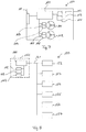
- a drive module 100 is shown, which can be used for the modular construction of an aircraft.
- the drive module comprises two rotors 101, 102.
- the rotor 101 is driven by a drive motor 103, the angle of incidence of the rotor blades of the rotor 101 takes place via a servomotor 104.
- a drive motor 105 and a servomotor 106 are accordingly provided for the rotor 102.
- a module controller 110 controls the motors 103, 104, 105, 106 as a function of setpoint values for the lift to be supplied by the drive module 100 and a torque to be supplied by the drive module if necessary.
- the module controller 110 receives the corresponding setpoint values via a data interface 111 from a central controller, which is shown in FIG Figure 7 is not shown.
- the drive module 100 can have sensors for the flight attitude, for example a position sensor 112, for example a GPS sensor, an altimeter 113, and an inclination sensor 114.
- the measured values of the sensors 112, 113, 114 can be transmitted from the module controller 110 to the central controller via the data interface 111.
- the module controller 110 can transmit operating data to the central controller via the data interface 111.
- FIG 8 a modular aircraft 150 is shown schematically.
- the aircraft 150 comprises a nacelle 151, which is connected to six drive modules 152, 153, 154, 155, 156, 157.
- the drive modules 152, 153, 154, 155, 156, 157 are designed like the drive module 100 and are not described again here.
- a mechanical connection of the drive modules 152, 153, 154, 155, 156, 157 with the gondola 151 is not shown; it can be done via standardized mechanical connecting elements.
- a central control 160 is provided in the gondola 151, which is connected to the drive modules 152, 153, 154, 155, 156, 157 via a data connection 161.
- the data connection 161 can be a known bus system, such as a CAN bus or a field bus.
- the central control 160 is also connected to flight attitude sensors 162, 163, 164, which are as above Figure 7 described can be position sensors, height sensors and inclination sensors.
- the central control can use the data from the flight attitude sensors 162, 163, 164 and specified course parameters to determine setpoint values for the lift forces and torques to be supplied by the drive modules 152, 153, 154, 155, 156, 157, and transmits these to the appropriate ones via the data line 161 Drive modules 152, 153, 154, 155, 156, 157.
- the central control 160 only needs to know how many drive modules are connected to the gondola 151 and at which points they are mounted.
- the central control 160 does not require any detailed information about the structure of the individual drive modules 152, 153, 154, 155, 156, 157, such as the number of rotors and / or characteristic fields of the rotor blades with regard to speed, angle of attack and lift force. Such data are stored in the module controls of the drive modules 152, 153, 154, 155, 156, 157.
- the drive modules 152, 153, 154, 155, 156, 157 are kept ready with certain standardized characteristic values and can be put together accordingly if required.
- drive modules with rotor radii of 1m, 2m and 3m can be provided, and optionally with one or two rotors per module.
- an adapted aircraft 150 can be put together quickly for a specific transport task by determining the type and number of drive modules on the basis of the total lift force required. Complex individual dimensioning of the drive units and corresponding parameterization of the control of the aircraft 150 can thereby be significantly simplified or even omitted entirely.
- control concept described here for a modular aircraft is only to be understood as an example; alternative control concepts can also be used.
- the energy supply of the drive modules 100, 152, 153, 154, 155, 156, 157 is not shown. It can either take place from a central power supply unit, or each module 100, 152, 153, 154, 155, 156, 157 can have its own power supply. Batteries or accumulators, for example, come into consideration as the energy supply unit.
Applications Claiming Priority (1)
| Application Number | Priority Date | Filing Date | Title |
|---|---|---|---|
| DE102019125460.4A DE102019125460A1 (de) | 2019-09-20 | 2019-09-20 | Fluggerät und Antriebseinheit |
Publications (1)
| Publication Number | Publication Date |
|---|---|
| EP3795469A1 true EP3795469A1 (fr) | 2021-03-24 |
Family
ID=72603396
Family Applications (1)
| Application Number | Title | Priority Date | Filing Date |
|---|---|---|---|
| EP20197156.1A Pending EP3795469A1 (fr) | 2019-09-20 | 2020-09-21 | Aéronef et unité d'entrainement |
Country Status (2)
| Country | Link |
|---|---|
| EP (1) | EP3795469A1 (fr) |
| DE (1) | DE102019125460A1 (fr) |
Cited By (1)
| Publication number | Priority date | Publication date | Assignee | Title |
|---|---|---|---|---|
| CN114435603A (zh) * | 2022-02-24 | 2022-05-06 | 广东汇天航空航天科技有限公司 | 多旋翼飞行控制方法、飞行控制器及飞行器 |
Citations (5)
| Publication number | Priority date | Publication date | Assignee | Title |
|---|---|---|---|---|
| WO2016164280A1 (fr) * | 2015-04-04 | 2016-10-13 | Skylift Global | Véhicule à rotors multiples à commande de mouvement de lacet et autorotation |
| KR101772570B1 (ko) * | 2017-02-13 | 2017-09-12 | 이명근 | 가변피치 프로펠러를 이용한 드론의 추락방지 시스템 |
| WO2017172402A1 (fr) * | 2016-03-28 | 2017-10-05 | Amazon Technologies, Inc. | Unités de propulsion à poussée sélective pour véhicules aériens |
| US20190161179A1 (en) * | 2016-04-07 | 2019-05-30 | AileLinX Inc. | Helicopter Rotor Head, Multirotor Helicopter, and Helicopter |
| US20190176979A1 (en) * | 2016-08-22 | 2019-06-13 | Denso Corporation | Flying device |
Family Cites Families (4)
| Publication number | Priority date | Publication date | Assignee | Title |
|---|---|---|---|---|
| CA2869734A1 (fr) * | 2012-04-09 | 2014-01-09 | Frick A. Smith | Avion pourvu d'un moteur en roue libre |
| EP2990332A1 (fr) * | 2014-08-19 | 2016-03-02 | Tau Emerald Rotors Inc. | Controle d'aéronef à voilure tournante |
| SG11201912916XA (en) * | 2017-06-01 | 2020-01-30 | Surefly Inc | Auxiliary power system for rotorcraft with folding propeller arms and crumple zone landing gear |
| US10829200B2 (en) * | 2017-11-09 | 2020-11-10 | Bell Helicopter Textron Inc. | Multirotor aircraft with collective for autorotation |
-
2019
- 2019-09-20 DE DE102019125460.4A patent/DE102019125460A1/de active Pending
-
2020
- 2020-09-21 EP EP20197156.1A patent/EP3795469A1/fr active Pending
Patent Citations (5)
| Publication number | Priority date | Publication date | Assignee | Title |
|---|---|---|---|---|
| WO2016164280A1 (fr) * | 2015-04-04 | 2016-10-13 | Skylift Global | Véhicule à rotors multiples à commande de mouvement de lacet et autorotation |
| WO2017172402A1 (fr) * | 2016-03-28 | 2017-10-05 | Amazon Technologies, Inc. | Unités de propulsion à poussée sélective pour véhicules aériens |
| US20190161179A1 (en) * | 2016-04-07 | 2019-05-30 | AileLinX Inc. | Helicopter Rotor Head, Multirotor Helicopter, and Helicopter |
| US20190176979A1 (en) * | 2016-08-22 | 2019-06-13 | Denso Corporation | Flying device |
| KR101772570B1 (ko) * | 2017-02-13 | 2017-09-12 | 이명근 | 가변피치 프로펠러를 이용한 드론의 추락방지 시스템 |
Cited By (2)
| Publication number | Priority date | Publication date | Assignee | Title |
|---|---|---|---|---|
| CN114435603A (zh) * | 2022-02-24 | 2022-05-06 | 广东汇天航空航天科技有限公司 | 多旋翼飞行控制方法、飞行控制器及飞行器 |
| CN114435603B (zh) * | 2022-02-24 | 2022-12-20 | 广东汇天航空航天科技有限公司 | 多旋翼飞行控制方法、飞行控制器及飞行器 |
Also Published As
| Publication number | Publication date |
|---|---|
| DE102019125460A1 (de) | 2021-03-25 |
Similar Documents
| Publication | Publication Date | Title |
|---|---|---|
| EP3176084B1 (fr) | Procédé d'amélioration des qualités de vol d'un muticoptère dans des situations de panne et multicoptère présentant des qualités de vol améliorées dans des situations de panne | |
| EP0948441B1 (fr) | Aeronef avec un fuselage en forme de corps aerodynamique de sustentation | |
| DE2922059C2 (de) | Verbundflugzeug | |
| DE102017212716A1 (de) | Unbemanntes Flugzeug | |
| DE202017104421U1 (de) | Unbemanntes Flugzeug | |
| EP3795469A1 (fr) | Aéronef et unité d'entrainement | |
| DE2640433C2 (de) | Schubvektor-Luftschiff | |
| DE10321333B4 (de) | Zusammengesetzte Konstruktion zum Abschießen einer Nutzlast in den Raum | |
| DE3010903C2 (fr) | ||
| DE6923742U (de) | Flugzeug | |
| DE202014104120U1 (de) | Aktives Neigefahrwerk für ein schienenungebundenes Fahrzeug | |
| EP3177526B1 (fr) | Autogire | |
| WO2020193364A1 (fr) | Dispositif volant | |
| EP3508421A1 (fr) | Mécanisme d'entraînement d'hélicoptère et procédé de fonctionnement d'un mécanisme d'entraînement d'hélicoptère | |
| EP4011770B1 (fr) | Avion à propulsion électrique | |
| EP1685024B1 (fr) | Aeronef | |
| DE102021133301B3 (de) | VTOL-Luftfahrzeug mit batterieelektrischem Antrieb und Verbrennungsmotor | |
| DE19821268C2 (de) | Aktive Rotorblattverstellung durch Drallvektorregelung bzw. Drallvektorsteuerung | |
| DE102004007682A1 (de) | Luftfahrzeug | |
| DE102017123536B4 (de) | Luftfahrzeug | |
| DE857470C (de) | Flugzeug mit einem Tragwerk mit veraenderlicher Kruemmung | |
| EP4114726A1 (fr) | Aéronef présentant plusieurs modes de vol et procédé pour faire fonctionner cet aéronef | |
| EP2995536A2 (fr) | Vehicule comprenant un chassis tetraedrique | |
| DE2556907A1 (de) | Fluggeraet | |
| WO2024013392A1 (fr) | Aéronef à décollage vertical |
Legal Events
| Date | Code | Title | Description |
|---|---|---|---|
| PUAI | Public reference made under article 153(3) epc to a published international application that has entered the european phase |
Free format text: ORIGINAL CODE: 0009012 |
|
| STAA | Information on the status of an ep patent application or granted ep patent |
Free format text: STATUS: THE APPLICATION HAS BEEN PUBLISHED |
|
| AK | Designated contracting states |
Kind code of ref document: A1 Designated state(s): AL AT BE BG CH CY CZ DE DK EE ES FI FR GB GR HR HU IE IS IT LI LT LU LV MC MK MT NL NO PL PT RO RS SE SI SK SM TR |
|
| AX | Request for extension of the european patent |
Extension state: BA ME |
|
| STAA | Information on the status of an ep patent application or granted ep patent |
Free format text: STATUS: REQUEST FOR EXAMINATION WAS MADE |
|
| 17P | Request for examination filed |
Effective date: 20210917 |
|
| RBV | Designated contracting states (corrected) |
Designated state(s): AL AT BE BG CH CY CZ DE DK EE ES FI FR GB GR HR HU IE IS IT LI LT LU LV MC MK MT NL NO PL PT RO RS SE SI SK SM TR |
|
| STAA | Information on the status of an ep patent application or granted ep patent |
Free format text: STATUS: EXAMINATION IS IN PROGRESS |
|
| 17Q | First examination report despatched |
Effective date: 20230207 |
|
| P01 | Opt-out of the competence of the unified patent court (upc) registered |
Effective date: 20230302 |