EP3795469A1 - Aircraft and drive unit - Google Patents
Aircraft and drive unit Download PDFInfo
- Publication number
- EP3795469A1 EP3795469A1 EP20197156.1A EP20197156A EP3795469A1 EP 3795469 A1 EP3795469 A1 EP 3795469A1 EP 20197156 A EP20197156 A EP 20197156A EP 3795469 A1 EP3795469 A1 EP 3795469A1
- Authority
- EP
- European Patent Office
- Prior art keywords
- aircraft
- rotor
- attack
- drive
- angle
- Prior art date
- Legal status (The legal status is an assumption and is not a legal conclusion. Google has not performed a legal analysis and makes no representation as to the accuracy of the status listed.)
- Pending
Links
- 238000004891 communication Methods 0.000 claims description 2
- 230000007935 neutral effect Effects 0.000 description 13
- 230000008901 benefit Effects 0.000 description 8
- 230000008859 change Effects 0.000 description 3
- 238000005096 rolling process Methods 0.000 description 3
- 230000000694 effects Effects 0.000 description 2
- 230000007257 malfunction Effects 0.000 description 2
- 238000000034 method Methods 0.000 description 2
- 230000008569 process Effects 0.000 description 2
- RZVHIXYEVGDQDX-UHFFFAOYSA-N 9,10-anthraquinone Chemical compound C1=CC=C2C(=O)C3=CC=CC=C3C(=O)C2=C1 RZVHIXYEVGDQDX-UHFFFAOYSA-N 0.000 description 1
- 238000010276 construction Methods 0.000 description 1
- 230000007423 decrease Effects 0.000 description 1
- 230000003111 delayed effect Effects 0.000 description 1
- 230000001419 dependent effect Effects 0.000 description 1
- 238000005516 engineering process Methods 0.000 description 1
- 230000024703 flight behavior Effects 0.000 description 1
- 230000001141 propulsive effect Effects 0.000 description 1
- 230000001105 regulatory effect Effects 0.000 description 1
- 230000004044 response Effects 0.000 description 1
Images


Classifications
-
- B—PERFORMING OPERATIONS; TRANSPORTING
- B64—AIRCRAFT; AVIATION; COSMONAUTICS
- B64C—AEROPLANES; HELICOPTERS
- B64C27/00—Rotorcraft; Rotors peculiar thereto
- B64C27/54—Mechanisms for controlling blade adjustment or movement relative to rotor head, e.g. lag-lead movement
-
- B—PERFORMING OPERATIONS; TRANSPORTING
- B64—AIRCRAFT; AVIATION; COSMONAUTICS
- B64U—UNMANNED AERIAL VEHICLES [UAV]; EQUIPMENT THEREFOR
- B64U10/00—Type of UAV
- B64U10/10—Rotorcrafts
- B64U10/13—Flying platforms
- B64U10/16—Flying platforms with five or more distinct rotor axes, e.g. octocopters
-
- B—PERFORMING OPERATIONS; TRANSPORTING
- B64—AIRCRAFT; AVIATION; COSMONAUTICS
- B64U—UNMANNED AERIAL VEHICLES [UAV]; EQUIPMENT THEREFOR
- B64U50/00—Propulsion; Power supply
- B64U50/10—Propulsion
- B64U50/13—Propulsion using external fans or propellers
-
- B—PERFORMING OPERATIONS; TRANSPORTING
- B64—AIRCRAFT; AVIATION; COSMONAUTICS
- B64U—UNMANNED AERIAL VEHICLES [UAV]; EQUIPMENT THEREFOR
- B64U50/00—Propulsion; Power supply
- B64U50/10—Propulsion
- B64U50/13—Propulsion using external fans or propellers
- B64U50/14—Propulsion using external fans or propellers ducted or shrouded
-
- B—PERFORMING OPERATIONS; TRANSPORTING
- B64—AIRCRAFT; AVIATION; COSMONAUTICS
- B64U—UNMANNED AERIAL VEHICLES [UAV]; EQUIPMENT THEREFOR
- B64U50/00—Propulsion; Power supply
- B64U50/10—Propulsion
- B64U50/19—Propulsion using electrically powered motors
Definitions
- the invention relates to an aircraft comprising a nacelle and at least three drive units which are arranged around the nacelle in such a way that they span an area;
- Each drive unit comprises at least one rotor with an axis of rotation that runs essentially perpendicular to the surface spanned by the drive units, and each rotor has at least two, preferably at least three rotor blades, the pitch angle ⁇ of which is operationally adjustable in a predetermined angular range.
- the invention also relates to a drive unit of an aircraft.
- the lift generated by the individual drive units is controlled, in this way roll and pitch moments can be generated.
- a propulsive force results from the lift of the drive units, by means of which the aircraft moves forwards and / or sideways.
- a yaw moment is also obtained from the sum of the torques of all drive units of the aircraft. In the case of smaller multicopters, this is usually compensated for by providing an even number of drive units, half of which rotate clockwise and the other half counterclockwise. By correspondingly adapting the torques of the individual drive units, a yaw moment can be generated in a targeted manner in order to align the aircraft.
- Multicopter rotors usually have between two and six rotor blades with a fixed angle of attack. To change the lift and / or torque of a rotor, the speed of the rotor is changed.
- the rotor inertia When regulating the flight attitude of a multicopter with large rotors, the rotor inertia causes a delayed adjustment of the lift in response to a command from the controller. This leads to an increased tendency to overshoot in the event of sudden disturbances such as gusts. In order to reduce this influence, the drive motors of the rotors must be extremely powerful, which leads to a higher dead weight and thus to a lower payload of the aircraft.
- the speed of the rotors When picking up or putting down a payload, waiting times arise because the speed of the rotors must first be adapted to the changed load conditions. If, for example, a passenger is to get out of a multicopter used in passenger transport, the speed of the rotors should first be reduced after the multicopter has been put down so that the multicopter is sufficiently stable even after the passenger has got out, so as not to hit the straight in the event of a sudden gust being pressed and injuring the disembarked passenger. As a rule, the speed will have to be reduced to such an extent that the rotors no longer generate any lift. For the multicopter to fly on, the speed must be increased again.
- an aircraft comprising a nacelle and at least three drive units which are arranged around the nacelle in such a way that they span an area; wherein each drive unit comprises at least one rotor with an axis of rotation which runs essentially perpendicular to the surface spanned by the drive units, and each rotor has at least two, preferably at least three rotor blades, the pitch angle ⁇ of which is operationally adjustable in a predetermined angular range, which thereby It is further developed that the predetermined angular range includes an angle of attack at which a rotor blade does not generate any lift regardless of a rotational speed of the rotor.
- the angle of attack of a rotor blade at which the rotor blade does not generate any lift regardless of the speed of the rotor, is usually specified as 0 °; this setting is also referred to as the neutral position. Since the angle of incidence of the rotors can be set to 0 ° during operation, it is possible to safely park the aircraft with its entire weight at full speed of the rotors, while a passenger is getting on or off, for example, and after getting on or off take off again immediately by adjusting the angle of attack to a positive value without observing dead times.
- the angle of attack of a rotor blade is generally specified as the angle by which the rotor blade is rotated with respect to the neutral position.
- the specified angular range can include angles of attack at which a rotor blade generates negative lift.
- angles of attack are generally given as negative angles (a ⁇ 0 °).
- the aircraft can also be pressed onto the ground by the drive units in order to enable safe entry and exit.
- the provision of negative angles of attack increases the ability of the aircraft to react in the event of a drive unit failure. If, for example, one drive unit fails in an aircraft with four drive units arranged in the form of a square, the lift of the drive unit located diametrically opposite must be reduced to zero in order to prevent the aircraft from tipping over. The remaining drive units are then on one line and a control of roll moments is not possible with these drive units.
- the fourth drive unit can, however, be used to control rolling torques by keeping the corresponding rotor at speed and generating the required rolling torque as required by setting a positive or negative angle of attack.
- the intended angular range can include angles of attack between -5 ° and + 10 °.
- An angle of attack of -5 ° enables the autorotation, while an angle of attack of 10 ° with the usual dimensioning of rotor blades is sufficient to carry the full payload of the aircraft.
- the intended angular range can include angles of attack between -12 ° and + 12 °. With this extended angular range there is a further improved maneuverability of the aircraft.
- the rotors of the drive units of an aircraft according to the invention can have a radius of at least 1 m, preferably of at least 2 m. Corresponding rotor radii enable economically interesting payloads, with the advantages according to the invention in terms of maneuverability particularly coming into play.
- the drive units can each have a casing ring.
- casing rings increase the operational safety of aircraft according to the invention by significantly reducing the risk of the rotor blades colliding with objects and people.
- shroud rings suppress eddy currents at the outer ends of the rotor blades and thus increase the efficiency of the rotors.
- the rotor blades of an aircraft can have an offset of a maximum of 5 °.
- a twist is a twisting of the cross-sectional profile of a rotor blade along its longitudinal axis.
- a twist of 5 ° means that a chord of the cross-sectional profile rotates by 5 ° over the length of the rotor blade.
- a mean value or a median value of the local angle of attack along the longitudinal axis of the rotor blade can be used as the angle of attack of the rotor blade.
- the profile of the rotor blades can be adapted to the different rotational speeds along the rotor blade in order to achieve a distribution of the lift force that is as uniform as possible.
- Too great a twist does not make sense in rotors with an adjustable angle of attack, since this can result in too large angles of attack on the one hand at the outer or inner end of the rotor blade, which entail the risk of a stall.
- the offset in the area of the neutral position creates a Range of angles of attack in which the rotor blade has a partially positive angle of attack and partially a negative angle of attack along its longitudinal axis. In this range of angles of attack, the rotor generates practically no lift, but is strongly braked.
- each drive unit can have two coaxial rotors with opposite directions of rotation. With rotors lying closely one above the other along the axis of rotation, the lift force that can be achieved per rotor area can be increased. At the same time, the torques of the two rotors compensate each other to a large extent, so that the control of a yaw moment acting on the aircraft is simplified.
- the speed and / or the angle of attack of the rotor blades can preferably be controllable separately for each drive unit. This allows the flight behavior of the aircraft to be controlled particularly flexibly.
- the speed and / or the angle of attack of the rotor blades of both rotors can preferably be controlled independently of one another.
- the aircraft can have a modular structure, each drive unit being able to be constructed as an independent drive module, which comprises: at least one drive motor for the at least one rotor, at least one servomotor for setting the angle of attack of the rotor blades , a module controller for the at least one drive motor and / or the at least one servomotor, and a data interface for communication between the module controller and a central controller and / or further module controllers.
- standardized drive modules can be provided that are each designed for a specific nominal load capacity.
- a drive module with a simple rotor with a rotor radius of 1m can have a load capacity (lift force minus dead weight) of e.g. 200N
- a drive module with two coaxial rotors with a rotor radius of 2m can have a load capacity of 1000N.
- several such standardized drive modules can then be combined with a suitable nacelle to form an aircraft.
- Each drive module has a module control which controls the speed of the rotors of the drive unit and the angle of attack of the rotor blades.
- a separate drive motor and a separate servomotor for the angle of attack are preferably provided for each rotor of the drive unit.
- the module control has a data interface to Exchange operating data with a central controller.
- the central control can be equipped with sensors for determining the current flight attitude and position of the aircraft, and can determine setpoint values for lift and, if necessary, torque of the individual drive modules from the current determined data.
- the module controls receive the setpoints via their respective data interface, calculate the required speeds and the required angle of attack of the rotor blades for the rotors of the drive module, and control the drive and servo motors of the drive module accordingly.
- the central control can be installed in the nacelle.
- each module control can be designed in such a way that it can also provide the functionality of a central control.
- one of the module controls can then be selected to act as the central control.
- each module can additionally have sensors for determining the flight attitude.
- FIG. 1 an aircraft 1 is shown in a plan view.
- the aircraft 1 comprises a nacelle 2 and, in the example shown, four drive units 5, 6, 7, 8.
- the nacelle 2 can comprise a passenger compartment, a cargo gripper, and / or similar devices that are not shown in detail here.
- the drive units 5, 6, 7, 8 are arranged in one plane, here the plane of the drawing. Instead of the four drive units 5, 6, 7, 8, a different number of drive units be provided. At least three drive units are required for a stable flight position of the aircraft 1.
- Each of the drive units 5, 6, 7, 8 comprises a rotor with a plurality of rotor blades 10. While each rotor has four rotor blades 10 in the example shown, the number of rotor blades can be larger or smaller. Although rotors with only one rotor blade are technically possible, as a rule at least two, preferably at least three, rotor blades 10 are provided for each rotor. For reasons of flow dynamics, more than six rotor blades 10 are generally not advisable for a rotor.
- the axes of rotation of the rotors are essentially perpendicular to a plane spanned by the drive units 5, 6, 7, 8.
- the drive units 5, 6, 7, 8 generate lift in order to keep the aircraft 1 in the air. By varying the lift forces generated by the respective drive units 5, 6, 7, 8, pitch and roll moments can be generated in order to control the flight position of the aircraft 1.
- Each of the rotors additionally generates a torque, the torques of all rotors adding up to form a yaw moment acting on the aircraft 1.
- the rotors of the drive units 5 and 7 rotate in the opposite direction to the rotors of the drive units 6 and 8, so that the respective torques compensate each other for the same operating conditions of all rotors.
- the rotors of the drive units 5, 6, 7, 8 are each surrounded by casing rings 11.
- the casing rings 11 serve, on the one hand, to protect the rotor blades 10 from collisions with obstacles and, on the other hand, to suppress eddy currents at the outer ends of the rotor blades 10.
- the rotors of the drive units 5, 6, 7, 8 are driven by electric motors, not shown, which are arranged in hubs 15 of the rotors.
- the lift force provided by the respective drive units 5, 6, 7, 8 can be adjusted via the rotational speed of the rotors.
- the respective drive motors are controlled in such a way that they drive the rotors at a desired speed.
- rotors with large radii in particular have considerable moments of inertia, which means that the speed of these rotors can only be adjusted slowly.
- each of the rotors includes a servomotor.
- the aircraft 1 can leave the rotational speed of the rotors unchanged and only bring the rotor blades 10 into the neutral position, so that the drive units 5, 6, 7, 8 do not generate any lift.
- the aircraft 1 stands just as securely on the ground as an aircraft with stopped rotors.
- only the rotor blades 10 have to be adjusted in such a way that they generate the necessary lift. This adjustment is practically possible without delay.
- the rotor blade adjustment of the drive units 5, 6, 7, 8 is designed so that the angle of attack of the rotor blades 10 can be adjusted beyond the neutral position to angles of attack at which the rotor blades generate a negative lift force, i.e. a downforce.
- Corresponding angles of attack are referred to as negative angles of attack ⁇ ⁇ 0 °.
- the aircraft 1 By setting negative angles of attack, the aircraft 1 can be pressed firmly onto the ground during loading and unloading processes with the additional force of the drive units 5, 6, 7, 8, which further increases the stability of the aircraft, e.g. in the case of gusts from the side.
- FIG 2a the aircraft 1 is shown in a front view, only the gondola 2 and the drive units 6, 7, 8 being visible. If one of the drive units, in the illustrated case the drive unit 6, fails, the flight position of the aircraft 1 becomes unstable because the opposite drive unit 8 now generates a strong roll moment, while the drive units 5, 7 arranged along a longitudinal axis of the aircraft 1 carry the load Deliver buoyancy.
- the rotor blades 10 of the drive unit 8 can be brought into the neutral position, so that the drive unit 8 does not generate any lift force and thus also no roll moment.
- the drive unit 8 generates a torque even when the rotor blades 10 are in the neutral position, which counteracts the torques of the drive units 5 and 7 and thus reduces a yaw moment acting on the aircraft 1. Nevertheless, yawing of the aircraft 1 in the event of failure of one of the drive units 5, 6, 7, 8 cannot always be completely avoided.
- An autorotation can only be carried out if the adjustment of the rotor blades 10 functions in all drive units 5, 6, 7, 8.
- the aircraft 1 can be equipped with a passive rescue system (not shown), for example with a rescue parachute.
- FIG 3 a further aircraft 20 is shown. Unlike the aircraft 1 of the Figures 1 and 2 the aircraft 20 is equipped with eight drive units 21, 22, 23, 24, 25, 26, 27, 28.
- the aircraft 20 can transport larger loads than the aircraft 1.
- the mode of operation of the drive units 21, 22, 23, 24, 25, 26, 27, 27 and the maneuvering options in the event of a malfunction of individual drive units correspond to the explanations for the aircraft 1.
- the aircraft 20 can overall better compensate for the failure of one or even more drive units than the aircraft 1.
- a further drive unit 30 for an aircraft is shown. Unlike the previously explained drive units, the drive unit 30 has two rotors 31, 32, which rotate in opposite directions during operation. This is indicated by arrows 33, 34 in Figure 4 shown.
- the drive unit 30, like the drive units explained above, comprises a casing ring 35, which can be connected to the nacelle of an aircraft (not shown) via a carrier 36.
- a hub unit 38 is suspended within the casing ring 25 via three support struts 37.
- Drive motors, not shown, for the rotors 31, 32 are arranged in the hub unit 38.
- the upper rotor 31 comprises three rotor blades 40, the lower rotor 32 comprises three rotor blades 41.
- each of the rotors 31, 32 can have a different number of rotor blades, but preferably at least two and at most six.
- the number of rotor blades of the two rotors 31, 32 can be the same or different.
- the rotor blades 40, 41 are in turn adjustable in the angle of attack.
- Servomotors for adjusting the angle of attack of the rotor blades 40, 41 can also be arranged in the hub unit 38 and are not shown here.
- the drive unit 30 can generate a higher lift force than the previously illustrated drive units with only one rotor.
- An additional advantage is that the torques of the rotors 31, 32 can largely compensate one another, so that the drive unit 30 generates no or only a very low yaw moment as standard.
- the rotors 31, 32 can be controlled independently of one another in terms of speed and the angle of attack of the rotor blades 40, 41. This allows the lift force (or the output force) and the resulting torque of the drive unit 30 to be controlled over a wide range; at the same time, the speed and angle of attack of the rotors 31, 32 can be coordinated so that the air flow through the drive unit 30 is optimized.
- a possible profile of a rotor blade is shown, for example a rotor blade 40.
- the Figure 6a shows the rotor blade 40 in a plan view
- the Figures 6b to 6e Represents cross-sectional profiles of the rotor blade 40 in the planes A, B, C, D.
- the cross-sectional profile 42b of the rotor blade 40 is strongly curved in the plane A at the hub-side end of the rotor blade 40, and that the profile curvature 42c, 42d, 42e in the planes B, C and D in the direction of the outer end of the rotor blade 40 decreases.
- This change in profile takes into account the fact that the rotational speed of the rotor blade 40 increases towards the outside.
- a profile chord 43b of the profile in plane A is more inclined with respect to a plane of rotation of the rotor blade 40 than the profile chords 43c, 43d, 43e in planes B, C and D.
- the profile inclination in the plane A about 5 °, in plane B about 4 °, in plane C about 3 ° and in plane D about 2 °.
- the rotor blade 40 has an offset of approximately 3 °.
- the circumferential speed of the rotor blade 40 which increases towards the outside, is also taken into account by the twist.
- the rotor blade 40 has in the in Figure 6a to 6e
- the setting shown has an angle of attack between 5 ° and 2 °, an average angle of attack over the entire length of the rotor blade 40 being approximately 3.5 °.
- the rotor blade 40 generates a lift force which depends on the speed of the rotor.
- the angle of attack of the rotor blade 40 can be adjusted, for example up to an average angle of attack of 12 °.
- the angle of incidence in plane A is 13.5 °, in plane B 12.5 °, in plane C 11.5 °, and in plane D another 10.5 °.
- the mean angle of attack can be set to 0 °, with a positive angle of attack of 1.5 ° and 0.5 ° in planes A and B, while a positive angle of attack of 1.5 ° and 0.5 ° is present in planes C and D. there is a negative angle of incidence of -0.5 ° or -1.5 °.
- the opposite angles of attack along the rotor blade 40 ensure, on the one hand, that the resulting upward and downward forces largely cancel each other out. On the other hand, a noticeable braking force continues to act on the rotor blade 40 in this setting, so that the rotor continues to generate a torque which can be used to control a yaw moment of the aircraft.
- the angle of attack is adjusted so far that there is a negative angle of attack over the entire length of the rotor blade 40.
- the angle of attack in plane A is -0.5 °, in plane B -1.5 °, in plane C -2.5 °, and in plane D -3, 5 °.
- the rotor blade 40 has a symmetrical profile, ie the profile above the profile chord and the profile below the profile chord are mirror-symmetrical to one another.
- the rotor blade can also have an asymmetrical profile.
- a rotor blade with an asymmetrical profile can generate lift if the profile chord runs parallel to the axis of rotation of the rotor.
- the profile chord of a rotor blade with an asymmetrical profile runs in its neutral position at an angle to the axis of rotation of the rotor.
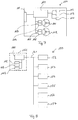
- a drive module 100 is shown, which can be used for the modular construction of an aircraft.
- the drive module comprises two rotors 101, 102.
- the rotor 101 is driven by a drive motor 103, the angle of incidence of the rotor blades of the rotor 101 takes place via a servomotor 104.
- a drive motor 105 and a servomotor 106 are accordingly provided for the rotor 102.
- a module controller 110 controls the motors 103, 104, 105, 106 as a function of setpoint values for the lift to be supplied by the drive module 100 and a torque to be supplied by the drive module if necessary.
- the module controller 110 receives the corresponding setpoint values via a data interface 111 from a central controller, which is shown in FIG Figure 7 is not shown.
- the drive module 100 can have sensors for the flight attitude, for example a position sensor 112, for example a GPS sensor, an altimeter 113, and an inclination sensor 114.
- the measured values of the sensors 112, 113, 114 can be transmitted from the module controller 110 to the central controller via the data interface 111.
- the module controller 110 can transmit operating data to the central controller via the data interface 111.
- FIG 8 a modular aircraft 150 is shown schematically.
- the aircraft 150 comprises a nacelle 151, which is connected to six drive modules 152, 153, 154, 155, 156, 157.
- the drive modules 152, 153, 154, 155, 156, 157 are designed like the drive module 100 and are not described again here.
- a mechanical connection of the drive modules 152, 153, 154, 155, 156, 157 with the gondola 151 is not shown; it can be done via standardized mechanical connecting elements.
- a central control 160 is provided in the gondola 151, which is connected to the drive modules 152, 153, 154, 155, 156, 157 via a data connection 161.
- the data connection 161 can be a known bus system, such as a CAN bus or a field bus.
- the central control 160 is also connected to flight attitude sensors 162, 163, 164, which are as above Figure 7 described can be position sensors, height sensors and inclination sensors.
- the central control can use the data from the flight attitude sensors 162, 163, 164 and specified course parameters to determine setpoint values for the lift forces and torques to be supplied by the drive modules 152, 153, 154, 155, 156, 157, and transmits these to the appropriate ones via the data line 161 Drive modules 152, 153, 154, 155, 156, 157.
- the central control 160 only needs to know how many drive modules are connected to the gondola 151 and at which points they are mounted.
- the central control 160 does not require any detailed information about the structure of the individual drive modules 152, 153, 154, 155, 156, 157, such as the number of rotors and / or characteristic fields of the rotor blades with regard to speed, angle of attack and lift force. Such data are stored in the module controls of the drive modules 152, 153, 154, 155, 156, 157.
- the drive modules 152, 153, 154, 155, 156, 157 are kept ready with certain standardized characteristic values and can be put together accordingly if required.
- drive modules with rotor radii of 1m, 2m and 3m can be provided, and optionally with one or two rotors per module.
- an adapted aircraft 150 can be put together quickly for a specific transport task by determining the type and number of drive modules on the basis of the total lift force required. Complex individual dimensioning of the drive units and corresponding parameterization of the control of the aircraft 150 can thereby be significantly simplified or even omitted entirely.
- control concept described here for a modular aircraft is only to be understood as an example; alternative control concepts can also be used.
- the energy supply of the drive modules 100, 152, 153, 154, 155, 156, 157 is not shown. It can either take place from a central power supply unit, or each module 100, 152, 153, 154, 155, 156, 157 can have its own power supply. Batteries or accumulators, for example, come into consideration as the energy supply unit.
Abstract
Es wird ein Fluggerät vorgestellt, umfassend eine Gondel (2, 151) und wenigstens drei Antriebseinheiten (5, 6, 7, 8, 21, 22, 23, 24, 25, 26, 27, 28, 30), welche so um die Gondel (2) angeordnet sind, dass sie eine Fläche aufspannen; wobei jede Antriebseinheit (5, 6, 7, 8, 21, 22, 23, 24, 25, 26, 27, 28, 30) wenigstens einen Rotor (31, 32, 101, 102) mit einer Rotationsachse umfasst, die im Wesentlichen senkrecht zu der durch die Antriebseinheiten (5, 6, 7, 8, 21, 22, 23, 24, 25, 26, 27, 28, 30) aufgespannten Fläche verläuft, und wobei jeder Rotor (31, 32, 101, 102) wenigstens zwei, bevorzugt wenigstens drei Rotorblätter (10, 40, 41) aufweist, deren Anstellwinkel α betriebsmäßig in einem vorgegebenen Winkelbereich verstellbar ist.An aircraft is presented, comprising a gondola (2, 151) and at least three drive units (5, 6, 7, 8, 21, 22, 23, 24, 25, 26, 27, 28, 30), which so around the Gondolas (2) are arranged so that they span a surface; wherein each drive unit (5, 6, 7, 8, 21, 22, 23, 24, 25, 26, 27, 28, 30) comprises at least one rotor (31, 32, 101, 102) with an axis of rotation that is essentially perpendicular to the surface spanned by the drive units (5, 6, 7, 8, 21, 22, 23, 24, 25, 26, 27, 28, 30), and each rotor (31, 32, 101, 102) has at least two, preferably at least three rotor blades (10, 40, 41), the angle of attack α of which can be adjusted during operation in a predetermined angular range.
Das Fluggerät zeichnet sich dadurch aus, dass der vorgegebenen Winkelbereich einen Anstellwinkel einschließt, bei welchem ein Rotorblatt (10, 40, 41) unabhängig von einer Drehzahl des Rotors (31, 32, 101, 102) keinen Auftrieb erzeugt (α = 0°).The aircraft is characterized by the fact that the specified angular range includes an angle of attack at which a rotor blade (10, 40, 41) does not generate any lift regardless of the speed of the rotor (31, 32, 101, 102) (α = 0 °) .
Weiterhin wird eine Antriebseinheit eines Fluggerätes vorgestellt.

Description
Die Erfindung betrifft ein Fluggerät, umfassend eine Gondel und wenigstens drei Antriebseinheiten, welche so um die Gondel angeordnet sind, dass sie eine Fläche aufspannen; wobei jede Antriebseinheit wenigstens einen Rotor mit einer Rotationsachse umfasst, die im Wesentlichen senkrecht zu der durch die Antriebseinheiten aufgespannten Fläche verläuft, und wobei jeder Rotor wenigstens zwei, bevorzugt wenigstens drei Rotorblätter aufweist, deren Anstellwinkel α betriebsmäßig in einem vorgegebenen Winkelbereich verstellbar ist.The invention relates to an aircraft comprising a nacelle and at least three drive units which are arranged around the nacelle in such a way that they span an area; Each drive unit comprises at least one rotor with an axis of rotation that runs essentially perpendicular to the surface spanned by the drive units, and each rotor has at least two, preferably at least three rotor blades, the pitch angle α of which is operationally adjustable in a predetermined angular range.
Weiterhin betrifft die Erfindung eine Antriebseinheit eines Fluggeräts.The invention also relates to a drive unit of an aircraft.
Gattungsgemäße Fluggeräte sind seit längerem bekannt und werden seit einiger Zeit hauptsächlich im Bereich kleinerer unbemannter Fluggeräte (Drohnen) eingesetzt. Aufgrund der Verwendung mehrerer Rotoren werden solche Fluggeräte zumeist als Multicopter bezeichnet.Generic aircraft have been known for a long time and have been used for some time mainly in the field of smaller unmanned aircraft (drones). Due to the use of several rotors, such aircraft are usually referred to as multicopters.
Zur Steuerung der Fluglage von Multicoptern wird der durch die einzelnen Antriebseinheiten erzeugte Auftrieb gesteuert, auf diese Weise können Roll- und Nickmomente erzeugt werden. Mittels einer entsprechend erzeugten Verkippung der durch die Antriebseinheiten aufgespannten Ebene ergibt sich aus dem Auftrieb der Antriebseinheiten eine Vortriebskraft, durch welche sich das Fluggerät vorwärts und/oder seitwärts bewegt.To control the flight attitude of multicopters, the lift generated by the individual drive units is controlled, in this way roll and pitch moments can be generated. By means of a correspondingly generated tilting of the plane spanned by the drive units, a propulsive force results from the lift of the drive units, by means of which the aircraft moves forwards and / or sideways.
Aus einer Summe der Drehmomente aller Antriebseinheiten des Fluggeräts ergibt sich zusätzlich ein Giermoment. Dies wird bei kleineren Multicoptern zumeist dadurch ausgeglichen, dass eine gerade Anzahl von Antriebseinheiten vorgesehen ist, von denen jeweils die Hälfte im Uhrzeigersinn und die andere Hälfte gegen den Uhrzeigersinn dreht. Durch entsprechende Anpassung der Drehmomente der einzelnen Antriebseinheiten kann gezielt ein Giermoment erzeugt werden, um das Fluggerät auszurichten.A yaw moment is also obtained from the sum of the torques of all drive units of the aircraft. In the case of smaller multicopters, this is usually compensated for by providing an even number of drive units, half of which rotate clockwise and the other half counterclockwise. By correspondingly adapting the torques of the individual drive units, a yaw moment can be generated in a targeted manner in order to align the aircraft.
Rotoren von Multicoptern haben üblicherweise zwischen zwei und sechs Rotorblätter mit festem Anstellwinkel. Zur Veränderung des Auftriebs und/oder Drehmoments eines Rotors wird die Drehzahl des Rotors verändert.Multicopter rotors usually have between two and six rotor blades with a fixed angle of attack. To change the lift and / or torque of a rotor, the speed of the rotor is changed.
Während die Flugsteuerung kleiner Multicopter über die Drehzahl der Antriebseinheiten recht zuverlässig funktioniert, stößt dieses Prinzip bei größeren Fluggeräten an Grenzen. Dies liegt zum einen an einer stark nichtlinearen Abhängigkeit zwischen Drehzahl und Auftrieb, insbesondere bei geringen Drehzahlen, und zum anderen an der mit dem Rotordurchmesser zunehmenden Trägheit der Rotoren.While the flight control of small multicopters works quite reliably via the speed of the drive units, this principle reaches its limits with larger aircraft. This is due, on the one hand, to a strongly non-linear relationship between speed and lift, especially at low speeds, and, on the other hand, to the inertia of the rotors, which increases with the rotor diameter.
Bei der Regelung der Fluglage eines Multicopters mit großen Rotoren bewirkt die Rotorträgheit eine verzögerte Anpassung des Auftriebs in Reaktion auf einen Stellbefehl der Steuerung. Dies führt zu einer verstärkten Neigung zu Überschwingungen bei plötzlichen Störeinflüssen wie Böen. Um diesen Einfluss zu reduzieren müssen Antriebsmotoren der Rotoren extrem leistungsstark ausgeführt werden, was zu einem höheren Eigengewicht und damit zu einer geringeren Nutzlast des Fluggeräts führt.When regulating the flight attitude of a multicopter with large rotors, the rotor inertia causes a delayed adjustment of the lift in response to a command from the controller. This leads to an increased tendency to overshoot in the event of sudden disturbances such as gusts. In order to reduce this influence, the drive motors of the rotors must be extremely powerful, which leads to a higher dead weight and thus to a lower payload of the aircraft.
Bei dem vermehrt diskutierten Einsatz von Multicoptem im Personen- und Gütertransport werden weitere Schwächen der Auftriebssteuerung über die Drehzahl der Rotoren deutlich.With the increasingly discussed use of multicopters in the transport of people and goods, further weaknesses in the control of lift via the speed of the rotors become clear.
So werden entstehen beim Aufnehmen oder Absetzen einer Nutzlast Wartezeiten dadurch, dass die Drehzahl der Rotoren zunächst an die geänderten Lastverhältnisse angepasst werden muss. Soll beispielsweise Fahrgast aus einem im Personentransport eingesetzten Multicopter aussteigen, so nach dem Aufsetzen des Multicopters zunächst die Drehzahl der Rotoren so weit reduziert werden, dass der Multicopter auch nach dem Aussteigen des Fahrgastes mit ausreichend stabil steht, um nicht bei einer plötzlichen Bö gegen den gerade ausgestiegenen Fahrgast gedrückt zu werden und diese zu verletzen. In der Regel wird dazu die Drehzahl so weit reduziert werden müssen, dass die Rotoren keinen Auftrieb mehr erzeugen. Zum Weiterflug des Multicopters muss die Drehzahl wieder erhöht werden.When picking up or putting down a payload, waiting times arise because the speed of the rotors must first be adapted to the changed load conditions. If, for example, a passenger is to get out of a multicopter used in passenger transport, the speed of the rotors should first be reduced after the multicopter has been put down so that the multicopter is sufficiently stable even after the passenger has got out, so as not to hit the straight in the event of a sudden gust being pressed and injuring the disembarked passenger. As a rule, the speed will have to be reduced to such an extent that the rotors no longer generate any lift. For the multicopter to fly on, the speed must be increased again.
Ein weiterer Nachteil bekannter Multicopter sind die beschränkten Möglichkeiten, auf einen Ausfall des Antriebs eines Rotors zu reagieren.Another disadvantage of known multicopters is the limited possibilities to react to a failure of the drive of a rotor.
Es ist vereinzelt vorgeschlagen worden, Multicopter mit Rotoren mit variablem Anstellwinkel der Rotorblätter auszustatten, um die Fluglageregelung zu verbessern. Die beschriebenen Probleme werden hierdurch jedoch nicht oder nicht vollständig gelöst.It has occasionally been proposed to equip multicopters with rotors with a variable angle of attack of the rotor blades in order to improve the attitude control. However, this does not, or does not completely, solve the problems described.
Es besteht daher eine Aufgabe der Erfindung darin, ein Fluggerät bereitzustellen, welches hinsichtlich der beschriebenen Problematiken verbessert ist.It is therefore an object of the invention to provide an aircraft which is improved with regard to the problems described.
Diese Aufgabe wird erfindungsgemäß gelöst durch ein Fluggerät, umfassend eine Gondel und wenigstens drei Antriebseinheiten, welche so um die Gondel angeordnet sind, dass sie eine Fläche aufspannen; wobei jede Antriebseinheit wenigstens einen Rotor mit einer Rotationsachse umfasst, die im Wesentlichen senkrecht zu der durch die Antriebseinheiten aufgespannten Fläche verläuft, und wobei jeder Rotor wenigstens zwei, bevorzugt wenigstens drei Rotorblätter aufweist, deren Anstellwinkel α betriebsmäßig in einem vorgegebenen Winkelbereich verstellbar ist, welches dadurch weitergebildet ist, dass der vorgegebenen Winkelbereich einen Anstellwinkel einschließt, bei welchem ein Rotorblatt unabhängig von einer Drehzahl des Rotors keinen Auftrieb erzeugt.According to the invention, this object is achieved by an aircraft comprising a nacelle and at least three drive units which are arranged around the nacelle in such a way that they span an area; wherein each drive unit comprises at least one rotor with an axis of rotation which runs essentially perpendicular to the surface spanned by the drive units, and each rotor has at least two, preferably at least three rotor blades, the pitch angle α of which is operationally adjustable in a predetermined angular range, which thereby It is further developed that the predetermined angular range includes an angle of attack at which a rotor blade does not generate any lift regardless of a rotational speed of the rotor.
Der Anstellwinkel eines Rotorblattes, bei dem das Rotorblatt unabhängig von der Drehzahl des Rotors keinen Auftrieb erzeugt, wird üblicherweise als 0° angegeben, diese Einstellung wird auch als Neutralstellung bezeichnet. Dadurch, dass der Anstellwinkel der Rotoren im Betrieb auf 0° eingestellt werden kann, ist es möglich, das Fluggerät bei voller Drehzahl der Rotoren sicher mit seinem ganzen Eigengewicht abzustellen, während beispielsweise ein Fahrgast ein- oder aussteigt, und nach dem Ein- oder Aussteigen durch Verstellung des Anstellwinkels auf einen positiven Wert ohne Einhaltung von Totzeiten sofort wieder abzuheben. Ausgehend von der Neutralstellung wird als Anstellwinkel eines Rotorblattes in der Regel der Winkel angegeben, um welchen das Rotorblatt gegenüber der Neutralstellung verdreht ist.The angle of attack of a rotor blade, at which the rotor blade does not generate any lift regardless of the speed of the rotor, is usually specified as 0 °; this setting is also referred to as the neutral position. Since the angle of incidence of the rotors can be set to 0 ° during operation, it is possible to safely park the aircraft with its entire weight at full speed of the rotors, while a passenger is getting on or off, for example, and after getting on or off take off again immediately by adjusting the angle of attack to a positive value without observing dead times. Starting from the neutral position, the angle of attack of a rotor blade is generally specified as the angle by which the rotor blade is rotated with respect to the neutral position.
In einer vorteilhaften Weiterbildung eines Fluggeräts gemäß der Erfindung kann der vorgegebene Winkelbereich Anstellwinkel einschießen, bei welchen ein Rotorblatt negativen Auftrieb erzeugt. Solche Anstellwinkel werden im allgemeinen als negative Winkel (a < 0°) angegeben.In an advantageous development of an aircraft according to the invention, the specified angular range can include angles of attack at which a rotor blade generates negative lift. Such angles of attack are generally given as negative angles (a <0 °).
Durch das Vorsehen negativer Anstellwinkel werden Einsatzmöglichkeiten eines erfindungsgemäßen Fluggeräts deutlich erweitert. So kann beispielsweise bei starken Winden das Fluggerät durch die Antriebseinheiten zusätzlich auf den Boden gedrückt werden, um ein sicheres Ein- und Aussteigen zu ermöglichen.By providing negative angles of attack, possible uses of an aircraft according to the invention are significantly expanded. In strong winds, for example, the aircraft can also be pressed onto the ground by the drive units in order to enable safe entry and exit.
Als weiterer Vorteil erweitert das Vorsehen negativer Anstellwinkel die Reaktionsmöglichkeiten des Fluggeräts bei Ausfall einer Antriebseinheit. Fällt beispielsweise bei einem Fluggerät mit vier Antriebseinheiten, die in Form eines Quadrats angeordnet sind, eine Antriebseinheit aus, so muss der Auftrieb der diametral gegenüber liegenden Antriebseinheit auf Null reduziert werden, um ein Überkippen des Fluggeräts zu verhindern. Die verbleibenden Antriebseinheiten liegen dann jedoch auf einer Linie und eine Steuerung von Rollmomenten ist mit diesen Antriebseinheiten nicht möglich. Die vierte Antriebseinheit kann jedoch zur Steuerung von Rollmomenten genutzt werden, indem der entsprechende Rotor auf Drehzahl gehalten wird und je nach Bedarf durch Einstellung eines positiven oder eines negativen Anstellwinkels das erforderliche Rollmoment erzeugt.As a further advantage, the provision of negative angles of attack increases the ability of the aircraft to react in the event of a drive unit failure. If, for example, one drive unit fails in an aircraft with four drive units arranged in the form of a square, the lift of the drive unit located diametrically opposite must be reduced to zero in order to prevent the aircraft from tipping over. The remaining drive units are then on one line and a control of roll moments is not possible with these drive units. The fourth drive unit can, however, be used to control rolling torques by keeping the corresponding rotor at speed and generating the required rolling torque as required by setting a positive or negative angle of attack.
Eine weitere Reaktionsmöglichkeit, die sich durch die möglichen negativen Anstellwinkel ergibt, ist die Autorotation. Ist eine Stabilisierung der Fluglage durch die verbleibenden Antriebseinheiten nicht möglich, so kann in allen Antriebseinheiten ein negativer Anstellwinkel eingestellt und durch die aus der Sinkbewegung resultierende Anströmung der Rotoren deren Drehzahl aufrecht erhalten oder gar erhöht werden. Die so in den Rotoren gespeicherte kinetische Energie kann dann genutzt werden, um das Fluggerät von dem Aufprall abzufangen und kontrolliert zu landen.Another possible reaction, which results from the possible negative angles of attack, is the autorotation. If the flight attitude cannot be stabilized by the remaining drive units, then a negative angle of attack can be set in all drive units and the rotors' speed can be maintained or even increased by the flow resulting from the sinking movement. The kinetic energy stored in this way in the rotors can then be used to intercept the aircraft from the impact and land in a controlled manner.
In einer bevorzugten Weiterbildung eines Fluggeräts gemäß der Erfindung kann der vorgesehene Winkelbereich Anstellwinkel zwischen -5° und +10° einschließen. Dabei ermöglicht ein Anstellwinkel von -5° die Autorotation, während ein Anstellwinkel von 10° bei üblicher Dimensionierung von Rotorblättern ausreicht, um die volle Nutzlast des Fluggeräts zu tragen.In a preferred development of an aircraft according to the invention, the intended angular range can include angles of attack between -5 ° and + 10 °. An angle of attack of -5 ° enables the autorotation, while an angle of attack of 10 ° with the usual dimensioning of rotor blades is sufficient to carry the full payload of the aircraft.
In einer weiteren bevorzugten Ausführung eines Fluggeräts gemäß der Erfindung kann der vorgesehene Winkelbereich Anstellwinkel zwischen -12° und +12° einschließen. Mit diesem erweiterten Winkelbereich besteht eine weiter verbesserte Manövrierfähigkeit des Fluggeräts.In a further preferred embodiment of an aircraft according to the invention, the intended angular range can include angles of attack between -12 ° and + 12 °. With this extended angular range there is a further improved maneuverability of the aircraft.
Die Rotoren der Antriebseinheiten eines Fluggeräts gemäß der Erfindung können einen Radius von wenigsten 1m, bevorzugt von wenigstens 2m aufweisen. Entsprechende Rotorradien ermöglichen wirtschaftlich interessante Nutzlasten, wobei die erfindungsgemäßen Vorteile in der Manövrierfähigkeit besonders zum Tragen kommen.The rotors of the drive units of an aircraft according to the invention can have a radius of at least 1 m, preferably of at least 2 m. Corresponding rotor radii enable economically interesting payloads, with the advantages according to the invention in terms of maneuverability particularly coming into play.
In einer bevorzugten Ausführung eines Fluggeräts gemäß der Erfindung können die Antriebseinheiten jeweils Mantelring aufweisen. Mantelringe erhöhen zum einen die Betriebssicherheit von erfindungsgemäßen Fluggeräten, indem sie die Gefahr von Kollisionen der Rotorblätter mit Objekten und Personen deutlich reduzieren. Zum anderen unterdrücken Mantelringe Wirbelströmungen an den äußeren Enden der Rotorblätter und erhöhen so die Effizienz der Rotoren.In a preferred embodiment of an aircraft according to the invention, the drive units can each have a casing ring. On the one hand, casing rings increase the operational safety of aircraft according to the invention by significantly reducing the risk of the rotor blades colliding with objects and people. On the other hand, shroud rings suppress eddy currents at the outer ends of the rotor blades and thus increase the efficiency of the rotors.
Die Rotorblätter eines Fluggeräts gemäß einer weiteren Ausführung der Erfindung können eine Schränkung von maximal 5° aufweisen. Als Schränkung wird eine Verdrehung des Querschnittprofils eines Rotorblattes entlang seiner Längsachse bezeichnet. Eine Schränkung von 5° bedeutet dabei, dass sich eine Profilsehne des Querschnittsprofils über die Länge des Rotorblattes um 5° verdreht. Bei geschränkten Rotorblättern kann ein Mittelwert oder ein Medianwert der lokalen Anstellwinkel entlang der Längsachse des Rotorblattes als Anstellwinkel des Rotorblattes verwendet werden.The rotor blades of an aircraft according to a further embodiment of the invention can have an offset of a maximum of 5 °. A twist is a twisting of the cross-sectional profile of a rotor blade along its longitudinal axis. A twist of 5 ° means that a chord of the cross-sectional profile rotates by 5 ° over the length of the rotor blade. In the case of set rotor blades, a mean value or a median value of the local angle of attack along the longitudinal axis of the rotor blade can be used as the angle of attack of the rotor blade.
Durch die Schränkung kann das Profil der Rotorblätter an die unterschiedlichen Umlaufgeschwindigkeiten entlang des Rotorblattes angepasst werden, um eine möglichst gleichförmige Verteilung der Auftriebskraft zu erreichen.As a result of the offset, the profile of the rotor blades can be adapted to the different rotational speeds along the rotor blade in order to achieve a distribution of the lift force that is as uniform as possible.
Eine zu starke Schränkung ist bei Rotoren mit verstellbarem Anstellwinkel allerdings nicht sinnvoll, da sich hierdurch einerseits am äußeren bzw. am inneren Ende des Rotorblattes zu große Anstellwinkel ergeben können, welche die Gefahr eines Strömungsabrisses mit sich bringen. Zum anderen entsteht durch die Schränkung im Bereich der Neutralstellung ein Bereich von Anstellwinkeln, in dem das Rotorblatt entlang seiner Längsachse teilweise einen positivem Anstellwinkel und teilweise einen negativen Anstellwinkel aufweist. In diesem Bereich von Anstellwinkeln erzeugt der Rotor praktisch keinen Auftrieb, wird jedoch stark gebremst.Too great a twist does not make sense in rotors with an adjustable angle of attack, since this can result in too large angles of attack on the one hand at the outer or inner end of the rotor blade, which entail the risk of a stall. On the other hand, the offset in the area of the neutral position creates a Range of angles of attack in which the rotor blade has a partially positive angle of attack and partially a negative angle of attack along its longitudinal axis. In this range of angles of attack, the rotor generates practically no lift, but is strongly braked.
In einer weiteren vorteilhaften Ausführung eines Fluggeräts gemäß der Erfindung kann jede Antriebseinheit zwei koaxiale Rotoren mit gegenläufiger Drehrichtung aufweisen. Durch entlang der Rotationsachse dicht übereinander liegende Rotoren kann die pro Rotorfläche erreichbare Auftriebskraft erhöht werden. Gleichzeitig kompensieren sich die Drehmomente der beiden Rotoren zu einem großen Teil, so dass die Steuerung eines auf das Fluggerät wirkenden Giermoments vereinfacht.In a further advantageous embodiment of an aircraft according to the invention, each drive unit can have two coaxial rotors with opposite directions of rotation. With rotors lying closely one above the other along the axis of rotation, the lift force that can be achieved per rotor area can be increased. At the same time, the torques of the two rotors compensate each other to a large extent, so that the control of a yaw moment acting on the aircraft is simplified.
Die Drehzahl und/oder der Anstellwinkel der Rotorblätter können bei einem Fluggerät gemäß der Erfindung vorzugsweise für jede Antriebseinheit separat steuerbar sein. Dadurch kann das Flugverhalten des Fluggeräts besonders flexibel gesteuert werden. Vorzugsweise sind bei Antriebseinheiten mit zwei koaxialen Rotoren die Drehzahl und/oder der Anstellwinkel der Rotorblätter beider Rotoren unabhängig voneinander steuerbar.In an aircraft according to the invention, the speed and / or the angle of attack of the rotor blades can preferably be controllable separately for each drive unit. This allows the flight behavior of the aircraft to be controlled particularly flexibly. In the case of drive units with two coaxial rotors, the speed and / or the angle of attack of the rotor blades of both rotors can preferably be controlled independently of one another.
In einer besonders bevorzugten Ausführung eines Fluggeräts gemäß der Erfindung kann das Fluggerät modular aufgebaut sein, wobei jede Antriebseinheit als eigenständiges Antriebsmodul aufgebaut sein kann, welches folgendes umfasst: wenigstens einen Antriebsmotor für den wenigstens einen Rotor, wenigstens einen Stellmotor für die Einstellung des Anstellwinkels der Rotorblätter, eine Modulsteuerung für den wenigstens einen Antriebsmotor und/oder den wenigstens einen Stellmotor, und eine Datenschnittstelle für eine Kommunikation zwischen der Modulsteuerung und einer Zentralsteuerung und/oder weiteren Modulsteuerungen.In a particularly preferred embodiment of an aircraft according to the invention, the aircraft can have a modular structure, each drive unit being able to be constructed as an independent drive module, which comprises: at least one drive motor for the at least one rotor, at least one servomotor for setting the angle of attack of the rotor blades , a module controller for the at least one drive motor and / or the at least one servomotor, and a data interface for communication between the module controller and a central controller and / or further module controllers.
Auf diese Weise können standardisierte Antriebsmodule bereitgestellt werden, die jeweils für eine bestimmte Nenntragkraft ausgelegt sind. Beispielsweise kann ein Antriebsmodul mit einem einfachen Rotor mit 1m Rotorradius eine Tragkraft (Auftriebskraft abzgl. Eigengewichtskraft) von z.B. 200N aufweisen, während ein Antriebsmodul mit zwei koaxialen Rotoren mit 2m Rotorradius eine Tragkraft von 1000N aufweisen kann. Je nach Anforderungen können dann mehrere solcher standardisierter Antriebsmodule mit einer geeigneten Gondel zu einem Fluggerät kombiniert werden.In this way, standardized drive modules can be provided that are each designed for a specific nominal load capacity. For example, a drive module with a simple rotor with a rotor radius of 1m can have a load capacity (lift force minus dead weight) of e.g. 200N, while a drive module with two coaxial rotors with a rotor radius of 2m can have a load capacity of 1000N. Depending on the requirements, several such standardized drive modules can then be combined with a suitable nacelle to form an aircraft.
Jedes Antriebsmodul weist eine Modulsteuerung auf, welche die Drehzahl der Rotoren der Antriebseinheit und die Anstellwinkel der Rotorblätter steuert. Dazu ist vorzugsweise für jeden Rotor der Antriebseinheit ein eigener Antriebsmotor und ein eigener Stellmotor für die Anstellwinkel vorgesehen. Die Modulsteuerung weist eine Datenschnittstelle auf, um Betriebsdaten mit einer Zentralsteuerung auszutauschen. Die Zentralsteuerung kann mit Sensoren zur Ermittlung der aktuellen Fluglage und Position des Fluggeräts ausgestattet sein, und aus den aktuellen ermittelten Daten Sollwerte für Auftrieb und ggf. Drehmoment der einzelnen Antriebsmodule ermitteln. Die Modulsteuerungen empfangen die Sollwerte über ihre jeweilige Datenschnittstelle, berechnen daraus die benötigten Drehzahlen und die benötigten Anstellwinkel der Rotorblätter für die Rotoren des Antriebsmoduls, und steuern die Antriebs- und Stellmotoren des Antriebsmoduls entsprechend.Each drive module has a module control which controls the speed of the rotors of the drive unit and the angle of attack of the rotor blades. For this purpose, a separate drive motor and a separate servomotor for the angle of attack are preferably provided for each rotor of the drive unit. The module control has a data interface to Exchange operating data with a central controller. The central control can be equipped with sensors for determining the current flight attitude and position of the aircraft, and can determine setpoint values for lift and, if necessary, torque of the individual drive modules from the current determined data. The module controls receive the setpoints via their respective data interface, calculate the required speeds and the required angle of attack of the rotor blades for the rotors of the drive module, and control the drive and servo motors of the drive module accordingly.
Die Zentralsteuerung kann in der Gondel installiert sein. Alternativ kann jede Modulsteuerung so ausgeführt sein, dass sie auch die Funktionalität einer Zentralsteuerung bereitstellen kann. Bei der Zusammenstellung der Antriebsmodule zu einem Fluggerät kann dann eine der Modulsteuerungen ausgewählt werden, als Zentralsteuerung zu fungieren. In diesem Fall kann jedes Modul zusätzlich Sensoren zur Ermittlung der Fluglage aufweisen.The central control can be installed in the nacelle. Alternatively, each module control can be designed in such a way that it can also provide the functionality of a central control. When the drive modules are put together to form an aircraft, one of the module controls can then be selected to act as the central control. In this case, each module can additionally have sensors for determining the flight attitude.
Die Aufgabe wird weiterhin gelöst durch eine Antriebseinheit eines Fluggeräts nach den obigen Ausführungen. Bezüglich der dadurch erreichbaren Vorteile und Wirkungen wird auf das oben gesagte ausdrücklich verwiesen.The object is also achieved by a drive unit of an aircraft according to the above statements. With regard to the advantages and effects that can be achieved in this way, express reference is made to what has been said above.
Die Erfindung wird nachfolgend anhand einiger beispielhafter Figuren näher erläutert, wobei die in den Figuren dargestellten Ausführungseispiele lediglich zum besseren Verständnis der Erfindung beitragen sollen, ohne diese einzuschränken.The invention is explained in more detail below with the aid of a few exemplary figures, the exemplary embodiments shown in the figures only intended to contribute to a better understanding of the invention without restricting it.
Es zeigen:
- Fig. 1:
- ein Fluggerät in einer Draufsicht,
- Fig. 2a-c:
- das Fluggerät der
Figur 1 in einer Frontansicht in verschiedenen Fluglagen, - Fig. 3:
- ein weiteres Fluggerät,
- Fig. 4:
- eine Antriebseinheit in einer Draufsicht,
- Fig. 5:
- eine Antriebseinheit in einer Schnittdarstellung,
- Fig. 6a-e:
- das Profil eines Rotorblattes,
- Fig. 7:
- ein Antriebsmodul in einer schematischen Darstellung,
- Fig. 8:
- ein modular aufgebautes Fluggerät in einer schematischen Darstellung.
- Fig. 1:
- an aircraft in a top view,
- Fig. 2a-c:
- the aircraft of the
Figure 1 in a front view in different flight positions, - Fig. 3:
- another aircraft,
- Fig. 4:
- a drive unit in a top view,
- Fig. 5:
- a drive unit in a sectional view,
- Fig. 6a-e:
- the profile of a rotor blade,
- Fig. 7:
- a drive module in a schematic representation,
- Fig. 8:
- a modular aircraft in a schematic representation.
In
Die Antriebseinheiten 5, 6, 7, 8 sind in einer Ebene, hier der Zeichenebene, angeordnet. Anstelle der vier Antriebseinheiten 5, 6, 7, 8 kann eine andere Anzahl von Antriebseinheiten vorgesehen sein. Dabei werden für eine stabile Fluglage des Fluggeräts 1 wenigstens drei Antriebseinheiten benötigt.The
Jede der Antriebseinheiten 5, 6, 7, 8 umfasst einen Rotor mit mehreren Rotorblättern 10. Während im dargestellten Beispiel jeder Rotor vier Rotorblätter 10 aufweist, kann die Anzahl der Rotorblätter größer oder kleiner sein. Obwohl Rotoren mit nur einem Rotorblatt technisch möglich sind, werden in der Regel wenigstens zwei, bevorzugt wenigstens drei Rotorblätter 10 für jeden Rotor vorgesehen sein. Aus strömungsdynamischen Gründen sind mehr als sechs Rotorblätter 10 für einen Rotor in der Regel nicht sinnvoll. Die Drehachsen der Rotoren stehen im Wesentlichen senkrecht zu einer durch die Antriebseinheiten 5, 6, 7, 8 aufgespannten Ebene.Each of the
Die Antriebseinheiten 5, 6, 7, 8 erzeugen Auftrieb, um das Fluggerät 1 in der Luft zu halten. Durch Variation der durch die jeweiligen Antriebseinheiten 5, 6, 7, 8 erzeugten Auftriebskräfte lassen sich Nick- und Rollmomente erzeugen, um die Fluglage des Fluggeräts 1 zu steuern.The
Jeder der Rotoren erzeugt zusätzlich ein Drehmoment, wobei sich die Drehmomente aller Rotoren zu einem auf das Fluggerät 1 wirkenden Giermoment addieren. Dabei rotieren die Rotoren der Antriebseinheiten 5 und 7 entgegengesetzt zu den Rotoren der Antriebseinheiten 6 und 8, so dass sich die jeweiligen Drehmomente bei gleichen Betriebsbedingungen aller Rotoren kompensieren.Each of the rotors additionally generates a torque, the torques of all rotors adding up to form a yaw moment acting on the
Die Rotoren der Antriebseinheiten 5, 6, 7, 8, sind jeweils von Mantelringen 11 umgeben. Die Mantelringe 11 dienen einerseits zum Schutz der Rotorblätter 10 vor Kollisionen mit Hindernissen und andererseits zum Unterdrücken von Wirbelströmungen an den äußeren Enden der Rotorblätter 10.The rotors of the
Die Rotoren der Antriebseinheiten 5, 6, 7, 8 werden durch nicht dargestellte Elektromotoren angetrieben, die in Naben 15 der Rotoren angeordnet sind.The rotors of the
Über die Drehzahl der Rotoren kann die durch die jeweiligen Antriebseinheiten 5, 6, 7, 8 bereitgestellte Auftriebskraft eingestellt werden. Dazu werden die jeweiligen Antriebsmotoren so gesteuert, dass sie die Rotoren mit einer gewünschten Drehzahl antreiben. Allerdings weisen insbesondere Rotoren mit großen Radien erhebliche Trägheitsmomente auf, was dazu führt, dass die Drehzahl dieser Rotoren nur langsam verstellt werden kann.The lift force provided by the
Für eine schnelle Veränderung der durch eine der Antriebseinheiten 5, 6,7, 8 bereitgestellte Auftriebskraft, wie sie insbesondere für die Fluglageregelung erforderlich sein kann, können die Rotorblätter 10 zusätzlich im Anstellwinkel verstellt werden. Hierzu umfasst jeder der Rotoren einen Stellmotor.For a rapid change in the lift force provided by one of the
Für die technische Umsetzung der Verstellung der Anstellwinkel der Rotorblätter 10 stehen dem Fachmann verschiedene Lösungen zur Verfügung, die hier nicht im Detail beschrieben werden sollen. Dabei ist in der Regel eine von der Drehwinkelstellung der Rotorblätter 10 unabhängige Einstellung des Anstellwinkels ausreichend, so dass auf eine aus dem Hubschrauberbereich bekannte Taumelscheibe verzichtet werden kann. In besonderen Einzelfällen kann jedoch auch eine drehwinkelabhängige Verstellung erforderlich sein, wobei auf die oben genannte Technologie mit Taumelscheibe zurückgegriffen werden kann.Various solutions are available to those skilled in the art for the technical implementation of the adjustment of the angle of attack of the
Der Anstellwinkel der Rotorblätter 10 ist in einem Winkelbereich verstellbar, der einen Anstellwinkel einschließt, bei welchem die Rotorblätter 10 unabhängig von Ihrer Drehzahl keinen Auftrieb mehr erzeugen. Dieser Anstellwinkel wird auch als Neutralstellung genannt und in der Regel mit einem Anstellwinkel a=0° bezeichnet.The angle of attack of the
Die Möglichkeit, die Rotorblätter in Neutralstellung zu bringen, bietet erhebliche Vorteile bei Be- und Entladungsvorgängen des Fluggeräts 1. Soll z.B. das Fluggerät einen Passagier befördern, so muss das Fluggerät 1 während des Ein- und Aussteigens des Passagiers sicher auf dem Boden stehen. Dazu dürfen die Antriebseinheiten 5, 6, 7, 8 keinen oder nur sehr wenig Auftriebskraft erzeugen, da andernfalls das Fluggerät 1 nur wenig Bodenhaftung aufweist und durch seitliche Böen leicht bewegt werden kann. Hierbei besteht dann eine erhebliche Unfallgefahr.The possibility of bringing the rotor blades into the neutral position offers considerable advantages when loading and unloading the
Herkömmliche Fluggeräte reduzieren dazu die Drehzahl der Rotoren auf null. Dies hat jedoch zur Folge, dass nach dem Einsteigen des Passagiers zunächst die Rotoren beschleunigt werden müssen, was bei Rotoren mit großem Radius wegen der hohen Trägheitsmomente einige Zeit in Anspruch nehmen kann. Während dies in den meisten zivilen Anwendungsfällen bestenfalls ärgerlich ist, kann diese Wartezeit bei Rettungseinsätzen oder bei Einsätzen im militärischen Bereich eine verheerende Wirkung haben.Conventional aircraft reduce the speed of the rotors to zero. However, this has the consequence that after boarding the passenger, the rotors must first be accelerated, which can take some time in the case of rotors with a large radius because of the high moments of inertia. While this is annoying at best in most civilian use cases, this waiting time can have a devastating effect in rescue operations or in military operations.
Im Gegensatz dazu kann das Fluggerät 1 die Drehzahl der Rotoren unverändert lassen und lediglich die Rotorblätter 10 in Neutralstellung bringen, so dass die Antriebseinheiten 5, 6, 7, 8 keinen Auftrieb erzeugen. Dadurch steht das Fluggerät 1 genau so sicher auf dem Boden wie ein Fluggerät mit angehaltenen Rotoren. Um nach dem Ein- oder Aussteigen der Passagiere zu starten, müssen lediglich die Rotorblätter 10 so verstellt werden, dass sie den benötigten Auftrieb erzeugen. Diese Verstellung ist praktisch Verzögerungsfrei möglich.In contrast to this, the
Ähnliche Vorteile lassen sich durch die Neutralstellung der Rotorblätter 10 bei Be- und Entladevorgängen im Gütertransport erreichen. Soll das Fluggerät 1 beispielsweise eine Nutzlast, z.B. einen Container absetzen, so kann eine Verbindung zwischen der Nutzlast und der Gondel 2 des Fluggeräts 1 erst dann gelöst werden, wenn die Auftriebskraft der Antriebseinheiten 5, 6, 7, 8 praktisch auf null reduziert ist. Andernfalls würde das Fluggerät 1 nach dem Lösen der Verbindung durch die Auftriebskraft der Antriebseinheiten 5, 6, 7, 8, in die Höhe gerissen, was wiederum zu Unfällen führen könnte.Similar advantages can be achieved by the neutral position of the
Weiterhin ist die Rotorblattverstellung der Antriebseinheiten 5, 6, 7, 8 so ausgeführt, dass der Anstellwinkel der Rotorblätter 10 über die Neutralstellung hinaus zu Anstellwinkeln verstellt werden kann, bei denen die Rotorblätter eine negative Auftriebskraft, also eine Abtriebskraft erzeugen. Entsprechende Anstellwinkel werden als negative Anstellwinkel α<0° bezeichnet.Furthermore, the rotor blade adjustment of the
Durch Einstellen von negativen Anstellwinkeln kann das Fluggerät 1 bei Be- und Entladevorgängen mit der zusätzlichen Abtriebskraft der Antriebseinheiten 5, 6, 7, 8 fest auf den Boden gedrückt werden, was die Stabilität des Fluggeräts z.B. bei seitlichen Böen weiter erhöht.By setting negative angles of attack, the
Die Möglichkeit, neutrale und sogar negative Anstellwinkel der Rotorblätter 10 einzustellen, bietet auch zusätzliche Reaktionsmöglichkeiten bei Betriebsstörungen einer der Antriebseinheiten 5, 6, 7, 8, wie im Folgenden anhand der
In
Bei Fluggeräten nach dem Stand der Technik müsste der Rotor der Antriebseinheit 8 gestoppt werden, um das Rollmoment zu beseitigen. Allerdings kann das Fluggerät dann auf externe Rollmomente, z.B. durch Seitenwind, nicht mehr reagieren.In the case of aircraft according to the prior art, the rotor of the
Bei dem vorliegenden Fluggerät 1 können hingegen die Rotorblätter 10 der Antriebseinheit 8 in die Neutralstellung gebracht werden, so dass die Antriebseinheit 8 keine Auftriebskraft und somit auch kein Rollmoment erzeugt.In the
Führt hingegen das Fluggerät 1 aufgrund äußerer Einflüsse eine Rollbewegung aus, wie es in den
Ein weiterer Vorteil besteht hier darin, dass die Antriebseinheit 8 auch bei Neutralstellung der Rotorblätter 10 ein Drehmoment erzeugt, welches den Drehmomenten der Antriebseinheiten 5 und 7 entgegenwirkt und somit ein auf das Fluggerät 1 wirkendes Giermoment reduziert. Gleichwohl wird sich ein Gieren des Fluggeräts 1 bei Ausfall einer der Antriebseinheiten 5, 6, 7, 8 nicht immer ganz vermeiden lassen.Another advantage here is that the
Reicht bei Ausfall einer oder mehrerer der Antriebseinheiten 5, 6, 7, 8 die durch die verbleibenden Antriebseinheiten erreichbare Auftriebskraft nicht aus, um das Fluggerät 1 zu tragen, so kommt als weitere Maßnahme die sogenannte Autorotation in Frage, bei welcher alle Antriebseinheiten 5, 6, 7, 8 deaktiviert und die Rotorblätter aller Antriebseinheiten 5, 6, 7, 8 in einen negativen Anstellwinkel gebracht werden. Die Rotoren werden bei dem dann einsetzenden Sinkflug von der durch die Rotorebenen strömende Luft angetrieben. Kurz vor dem Aufsetzen wird dann wieder ein positiver Anstellwinkel eingestellt, um das Fluggerät 1 abzufangen und sanft aufzusetzen. Während des Sinkfluges kann durch unterschiedliche Anstellwinkel an den einzelnen Antriebseinheiten 5, 6, 7, 8 weiterhin in gewissen Grenzen eine Fluglageregelung erfolgen.If, in the event of failure of one or more of the
Eine Autorotation kann nur durchgeführt werden, wenn bei allen Antriebseinheiten 5, 6, 7, 8 die Verstellung der Rotorblätter 10 funktioniert. Um auch bei Ausfall der Rotorblattverstellung einen Absturz zu vermeiden kann das Fluggerät 1 mit einem nicht dargestellten passiven Rettungssystem ausgestattet sein, beispielsweise mit einem Rettungsfallschirm.An autorotation can only be carried out if the adjustment of the
In
Durch die größere Anzahl an Antriebseinheiten kann das Fluggerät 20 größere Lasten transportieren als das Fluggerät 1. Die Funktionsweise der Antriebseinheiten 21, 22, 23, 24, 25, 26, 27, 27 und die Manövriermöglichkeiten bei Fehlfunktion einzelnen Antriebseinheiten entsprechen dabei den Ausführungen zum Fluggerät 1. Natürlich kann das Fluggerät 20 insgesamt den Ausfall einer oder gar mehrerer Antriebseinheiten besser kompensieren als das Fluggerät 1.Due to the larger number of drive units, the aircraft 20 can transport larger loads than the
In den
Die Antriebseinheit 30 umfasst ebenso wie die zuvor erläuterten Antriebseinheiten einen Mantelring 35, welcher über einen Träger 36 mit der Gondel eines nicht dargestellten Fluggeräts verbunden werden kann.The
Innerhalb des Mantelrings 25 ist über drei Tragstreben 37 eine Nabeneinheit 38 aufgehängt. In der Nabeneinheit 38 sind nicht dargestellte Antriebsmotoren für die Rotoren 31, 32 angeordnet.A hub unit 38 is suspended within the
Der obere Rotor 31 umfasst drei Rotorblätter 40, der untere Rotor 32 umfasst drei Rotorblätter 41. Alternative kann jeder der Rotoren 31, 32 eine andere Anzahl von Rotorblättern aufweisen, bevorzugt jedoch mindestens zwei und höchstens sechs. Dabei kann die Anzahl der Rotorblätter der beiden Rotoren 31, 32 gleich oder unterschiedlich sein.The
Die Rotorblätter 40, 41 sind wiederum im Anstellwinkel verstellbar. Stellmotoren für die Verstellung der Anstellwinkel der Rotorblätter 40, 41 können ebenfalls in der Nabeneinheit 38 angeordnet sein und sind hier nicht dargestellt.The
Die Antriebseinheit 30 kann aufgrund der zwei Rotoren 31, 32 eine höhere Auftriebskraft erzeugen als die zuvor dargestellten Antriebseinheiten mit lediglich einem Rotor. Ein zusätzlicher Vorteil besteht darin, dass die Drehmomente der Rotoren 31, 32 sich zu einem großen Teil gegenseitig kompensieren können, so dass die Antriebseinheit 30 standardmäßig kein oder nur ein sehr geringes Giermoment erzeugt.Due to the two
Die Rotoren 31, 32 sind unabhängig voneinander hinsichtlich Drehzahl und dem Anstellwinkel der Rotorblätter 40, 41 steuerbar. Dadurch lassen sich die Auftriebskraft (oder die Abtriebskraft) und das resultierende Drehmoment der Antriebseinheit 30 in weiten Bereichen steuern, gleichzeitig können Drehzahl und Anstellwinkel der Rotoren 31, 32 so aufeinander abgestimmt werden, dass die Luftströmung durch die Antriebseinheit 30 optimiert wird.The
In den
Die
Es ist erkennbar, dass das Querschnittsprofil 42b des Rotorblattes 40 in der Ebene A am nabenseitigen Ende des Rotorblattes 40 stark gewölbt ist, und dass die Profilwölbung 42c, 42d, 42e in den Ebenen B, C und D in Richtung zum äußeren Ende des Rotorblattes 40 abnimmt. Diese Änderung des Profils trägt der Tatsache Rechnung, dass die Umlaufgeschwindigkeit des Rotorblattes 40 nach außen hin zunimmt.It can be seen that the cross-sectional profile 42b of the
Weiterhin ist erkennbar, dass eine Profilsehne 43b des Profils in der Ebene A stärker gegenüber einer Umlaufebene des Rotorblattes 40 geneigt ist, als die Profilsehnen 43c, 43d, 43e in den Ebenen B, C und D. Im dargestellten Beispiel beträgt die Profilneigung in der Ebene A etwa 5°, in der Ebene B etwa 4°, in der Ebene C etwa 3° und in der Ebene D noch etwa 2°. Dementsprechend weist das Rotorblatt 40 eine Schränkung von etwa 3° auf. Durch die Schränkung wird ebenfalls der nach außen hin zunehmenden Umlaufgeschwindigkeit des Rotorblattes 40 Rechnung getragen.It can also be seen that a profile chord 43b of the profile in plane A is more inclined with respect to a plane of rotation of the
Das Rotorblatt 40 weist in der in
Soll das Rotorblatt 40 keinen Auftrieb erzeugen, so kann der mittlere Anstellwinkel auf 0° gestellt werden, wobei in den Ebenen A und B ein positiver Anstellwinkel von 1,5° bzw. 0,5° vorliegt, während in den Ebenen C und D ein negativer Anstellwinkel von -0,5° bzw. -1,5° vorliegt. Die entgegengesetzten Anstellwinkel entlang des Rotorblattes 40 sorgen einerseits dafür, dass sich die resultierenden Auf- und Abtriebskräfte größtenteils aufheben. Anderseits wirkt auf das Rotorblatt 40 in dieser Einstellung weiterhin eine nennenswerte Bremskraft, so dass der Rotor weiterhin ein Drehmoment erzeugt, welches zur Steuerung eines Giermoments des Fluggeräts genutzt werden kann.If the
Um eine Abtriebskraft zu erzeugen wird der Anstellwinkel so weit verstellt, dass über die gesamte Länge des Rotorblattes 40 ein negativer Anstellwinkel vorliegt. Bei einem mittleren Anstellwinkel von -2° beträgt z.B. der Anstellwinkel in der Ebene A -0,5°, in der Ebene B -1,5°, in der Ebene C -2,5°, und in der Ebene D -3,5°. Es zeigt sich, dass durch die Schränkung des Rotorblattes 40 jetzt der Betrag des Anstellwinkels am äußeren Ende des Rotorblattes größer ist als am inneren Ende. Das hat zur Folge, dass die Effizienz des Rotorblattes 40 bei negativen Anstellwinkeln durch die ungünstige Verteilung der Kräfte entlang des Rotorblattes reduziert ist. Dies kann aber angesichts der durch die oben beschriebenen Vorteile in Kauf genommen werden.In order to generate an output force, the angle of attack is adjusted so far that there is a negative angle of attack over the entire length of the
In den
In
Das Antriebsmodul umfasst im dargestellten Beispiel zwei Rotoren 101, 102. Der Rotor 101 wird durch einen Antriebsmotor 103 angetrieben, die Anstellwinkel der Rotorblätter des Rotors 101 erfolgt über einen Stellmotor 104. Entsprechend sind ein Antriebsmotor 105 und ein Stellmotor 106 für den Rotor 102 vorgesehen.In the example shown, the drive module comprises two
Eine Modulsteuerung 110 steuert die Motoren 103, 104, 105, 106 in Abhängigkeit von Sollwerten für den durch das Antriebsmodul 100 zu liefernden Auftrieb und ein ggf. durch das Antriebsmodul zu lieferndes Drehmoment. Die entsprechenden Sollwerte erhält die Modulsteuerung 110 über eine Datenschnittstelle 111 von einer Zentralsteuerung, die in
Zusätzlich kann das Antriebsmodul 100 Sensoren für die Fluglage aufweisen, dies können z.B. ein Positionssensor 112, beispielsweise ein GPS-Sensor, ein Höhenmesser 113, und ein Neigungssensor 114 sein. Die Messwerte der Sensoren 112, 113, 114 können von der Modulsteuerung 110 über die Datenschnittstelle 111 an die Zentralsteuerung übermittelt werden. Weiterhin kann die Modulsteuerung 110 Betriebsdaten über die Datenschnittstelle 111 an die Zentralsteuerung übertragen.In addition, the
In
Eine mechanische Verbindung der Antriebsmodule 152, 153, 154, 155, 156, 157 mit der Gondel 151 ist nicht dargestellt, sie kann über standardisierte mechanische Verbindungselemente erfolgen. In der Gondel 151 ist eine Zentralsteuerung 160 vorgesehen, welche über eine Datenverbindung 161 mit den Antriebsmodulen 152, 153, 154, 155, 156, 157 verbunden ist. Bei der Datenverbindung 161 kann es sich um ein bekanntes Bussystem handeln, wie beispielsweise einen CAN-Bus oder einen Field-Bus.A mechanical connection of the
Die Zentralsteuerung 160 ist weiterhin mit Fluglagesensoren 162, 163, 164 verbunden, bei denen es sich wie oben zu
Die Zentralsteuerung kann aus den Daten der Fluglagesensoren 162, 163, 164 und vorgegebenen Kursparametern Sollwerte für die durch die Antriebsmodule 152, 153, 154, 155, 156, 157 zu liefernden Auftriebskräfte und Drehmomente ermitteln, und überträgt diese über die Datenleitung 161 an die entsprechenden Antriebsmodule 152, 153, 154, 155, 156, 157. Dazu muss die Zentralsteuerung 160 lediglich wissen, wie viele Antriebsmodule mit der Gondel 151 verbunden sind, und an welchen Stellen diese montiert sind. Hingegen benötigt die Zentralsteuerung 160 keine detaillierten Informationen über den Aufbau der einzelnen Antriebsmodule 152, 153, 154, 155, 156, 157, wie z.B. Anzahl der Rotoren und/oder Kennlinienfelder der Rotorblätter hinsichtlich Drehzahl, Anstellwinkel und Auftriebskraft. Solche Daten sind in den Modulsteuerungen der Antriebsmodule 152, 153, 154, 155, 156, 157 hinterlegt.The central control can use the data from the
Die Antriebsmodule 152, 153, 154, 155, 156, 157 werden dabei mit bestimmten standardisierten Kennwerten bereitgehalten und können bei Bedarf entsprechend zusammengestellt werden. Beispielsweise können Antriebsmodule mit Rotorradien von 1m, 2m und 3m vorgehalten werden, und wahlweise mit jeweils einem oder zwei Rotoren pro Modul.The
Durch den entsprechenden modularen Aufbau kann für eine bestimmte Transportaufgabe schnell ein angepasstes Fluggerät 150 zusammengestellt werden, indem anhand der insgesamt benötigten Auftriebskraft Art und Anzahl der Antriebsmodule festgelegt wird. Eine aufwendige individuelle Dimensionierung der Antriebseinheiten sowie eine entsprechende Parameterisierung der Steuerung des Fluggeräts 150 können dadurch wesentlich vereinfacht werden oder gar ganz entfallen.Due to the corresponding modular structure, an adapted
Das hier beschriebene Steuerungskonzept für ein modular aufgebautes Fluggerät ist lediglich als Beispiel zu verstehen, alternative Steuerungskonzepte können ebenfalls Anwendung finden.The control concept described here for a modular aircraft is only to be understood as an example; alternative control concepts can also be used.
Die Energieversorgung der Antriebsmodule 100, 152, 153, 154, 155, 156, 157 ist nicht dargestellt. Sie kann entweder aus einer zentralen Energieversorgungseinheit erfolgen, oder jedes Modul 100, 152, 153, 154, 155, 156, 157 kann eine eigene Energieversorgung aufweisen. Als Energieversorgungseinheit kommen beispielsweise Batterien bzw. Akkumulatoren in Betracht.The energy supply of the
Claims (12)
jede Antriebseinheit (5, 6, 7, 8, 21, 22, 23, 24, 25, 26, 27, 28, 30) wenigstens einen Rotor (31, 32, 101, 102) mit einer Rotationsachse umfasst, die im Wesentlichen senkrecht zu der durch die Antriebseinheiten (5, 6, 7, 8, 21, 22, 23, 24, 25, 26, 27, 28, 30) aufgespannten Fläche verläuft, und wobei
jeder Rotor (31, 32, 101, 102) wenigstens zwei, bevorzugt wenigstens drei Rotorblätter (10, 40, 41) aufweist, deren Anstellwinkel α betriebsmäßig in einem vorgegebenen Winkelbereich verstellbar ist,
dadurch gekennzeichnet, dass der vorgegebenen Winkelbereich einen Anstellwinkel einschließt, bei welchem ein Rotorblatt (10, 40, 41) unabhängig von einer Drehzahl des Rotors (31, 32, 101, 102) keinen Auftrieb erzeugt (α = 0°).Aircraft, comprising a nacelle (2, 151) and at least three drive units (5, 6, 7, 8, 21, 22, 23, 24, 25, 26, 27, 28, 30), which so around the nacelle (2) are arranged to span a surface; in which
each drive unit (5, 6, 7, 8, 21, 22, 23, 24, 25, 26, 27, 28, 30) comprises at least one rotor (31, 32, 101, 102) with an axis of rotation that is essentially perpendicular to the area spanned by the drive units (5, 6, 7, 8, 21, 22, 23, 24, 25, 26, 27, 28, 30), and where
each rotor (31, 32, 101, 102) has at least two, preferably at least three rotor blades (10, 40, 41), the angle of attack α of which is operationally adjustable in a predetermined angular range,
characterized in that the specified angular range includes an angle of attack at which a rotor blade (10, 40, 41) does not generate any lift (α = 0 °) regardless of a rotational speed of the rotor (31, 32, 101, 102).
Applications Claiming Priority (1)
| Application Number | Priority Date | Filing Date | Title |
|---|---|---|---|
| DE102019125460.4A DE102019125460A1 (en) | 2019-09-20 | 2019-09-20 | Aircraft and propulsion unit |
Publications (1)
| Publication Number | Publication Date |
|---|---|
| EP3795469A1 true EP3795469A1 (en) | 2021-03-24 |
Family
ID=72603396
Family Applications (1)
| Application Number | Title | Priority Date | Filing Date |
|---|---|---|---|
| EP20197156.1A Pending EP3795469A1 (en) | 2019-09-20 | 2020-09-21 | Aircraft and drive unit |
Country Status (2)
| Country | Link |
|---|---|
| EP (1) | EP3795469A1 (en) |
| DE (1) | DE102019125460A1 (en) |
Cited By (1)
| Publication number | Priority date | Publication date | Assignee | Title |
|---|---|---|---|---|
| CN114435603A (en) * | 2022-02-24 | 2022-05-06 | 广东汇天航空航天科技有限公司 | Multi-rotor flight control method, flight controller and aircraft |
Citations (5)
| Publication number | Priority date | Publication date | Assignee | Title |
|---|---|---|---|---|
| WO2016164280A1 (en) * | 2015-04-04 | 2016-10-13 | Skylift Global | Multi-rotor vehicle with yaw control and autorotation |
| KR101772570B1 (en) * | 2017-02-13 | 2017-09-12 | 이명근 | Falling prevention system for drone using controllable pitch propeller |
| WO2017172402A1 (en) * | 2016-03-28 | 2017-10-05 | Amazon Technologies, Inc. | Selectively thrusting propulsion units for aerial vehicles |
| US20190161179A1 (en) * | 2016-04-07 | 2019-05-30 | AileLinX Inc. | Helicopter Rotor Head, Multirotor Helicopter, and Helicopter |
| US20190176979A1 (en) * | 2016-08-22 | 2019-06-13 | Denso Corporation | Flying device |
Family Cites Families (4)
| Publication number | Priority date | Publication date | Assignee | Title |
|---|---|---|---|---|
| WO2014007883A1 (en) * | 2012-04-09 | 2014-01-09 | Smith Frick A | Aircraft with freewheeling engine |
| US20160059958A1 (en) * | 2014-08-19 | 2016-03-03 | Tau Emerald Rotors Inc. | Controlling Rotary Wing Aircraft |
| WO2018222844A1 (en) * | 2017-06-01 | 2018-12-06 | Surefly, Inc. | Auxiliary power system for rotorcraft with folding propeller arms and crumple zone landing gear |
| US10829200B2 (en) * | 2017-11-09 | 2020-11-10 | Bell Helicopter Textron Inc. | Multirotor aircraft with collective for autorotation |
-
2019
- 2019-09-20 DE DE102019125460.4A patent/DE102019125460A1/en active Pending
-
2020
- 2020-09-21 EP EP20197156.1A patent/EP3795469A1/en active Pending
Patent Citations (5)
| Publication number | Priority date | Publication date | Assignee | Title |
|---|---|---|---|---|
| WO2016164280A1 (en) * | 2015-04-04 | 2016-10-13 | Skylift Global | Multi-rotor vehicle with yaw control and autorotation |
| WO2017172402A1 (en) * | 2016-03-28 | 2017-10-05 | Amazon Technologies, Inc. | Selectively thrusting propulsion units for aerial vehicles |
| US20190161179A1 (en) * | 2016-04-07 | 2019-05-30 | AileLinX Inc. | Helicopter Rotor Head, Multirotor Helicopter, and Helicopter |
| US20190176979A1 (en) * | 2016-08-22 | 2019-06-13 | Denso Corporation | Flying device |
| KR101772570B1 (en) * | 2017-02-13 | 2017-09-12 | 이명근 | Falling prevention system for drone using controllable pitch propeller |
Cited By (2)
| Publication number | Priority date | Publication date | Assignee | Title |
|---|---|---|---|---|
| CN114435603A (en) * | 2022-02-24 | 2022-05-06 | 广东汇天航空航天科技有限公司 | Multi-rotor flight control method, flight controller and aircraft |
| CN114435603B (en) * | 2022-02-24 | 2022-12-20 | 广东汇天航空航天科技有限公司 | Multi-rotor flight control method, flight controller and aircraft |
Also Published As
| Publication number | Publication date |
|---|---|
| DE102019125460A1 (en) | 2021-03-25 |
Similar Documents
| Publication | Publication Date | Title |
|---|---|---|
| EP2616333B1 (en) | Method for handling the failure of a lift rotor of a craft having multiple lift rotors and aircraft implementing said method | |
| EP0948441B1 (en) | Aircraft with a fuselage substantially designed as an aerostatic lifting body | |
| DE2922059C2 (en) | CONNECTED AIRPLANE | |
| DE102017212716A1 (en) | Unmanned aircraft | |
| DE202017104421U1 (en) | Unmanned aircraft | |
| EP1108647A1 (en) | Attitude control system for a load carrying parachute glider and its method of operation | |
| EP3795469A1 (en) | Aircraft and drive unit | |
| DE2640433C2 (en) | Thrust vector airship | |
| DE10321333B4 (en) | Composite construction for launching a payload into the room | |
| DE3010903C2 (en) | ||
| DE6923742U (en) | PLANE | |
| DE202014104120U1 (en) | Active tilting suspension for a trackless vehicle | |
| EP3177526B1 (en) | Autogyro | |
| EP3947144A1 (en) | Aircraft | |
| EP3508421A1 (en) | Helicopter drive and method for operating a helicopter drive | |
| EP4011770B1 (en) | Aircraft with electric drive | |
| EP1685024B1 (en) | Aircraft | |
| DE102021133301B3 (en) | VTOL aircraft with battery electric propulsion and internal combustion engine | |
| DE19821268C2 (en) | Active rotor blade adjustment by swirl vector control or swirl vector control | |
| DE102004007682A1 (en) | aircraft | |
| DE102017123536B4 (en) | Aircraft | |
| DE857470C (en) | Airplane with a wing with variable curvature | |
| EP4114726A1 (en) | Aircraft comprising a plurality of flying modes, and method for operating same | |
| EP2995536A2 (en) | Vehicle with tetrahedron frame | |
| DE2556907A1 (en) | AIRCRAFT |
Legal Events
| Date | Code | Title | Description |
|---|---|---|---|
| PUAI | Public reference made under article 153(3) epc to a published international application that has entered the european phase |
Free format text: ORIGINAL CODE: 0009012 |
|
| STAA | Information on the status of an ep patent application or granted ep patent |
Free format text: STATUS: THE APPLICATION HAS BEEN PUBLISHED |
|
| AK | Designated contracting states |
Kind code of ref document: A1 Designated state(s): AL AT BE BG CH CY CZ DE DK EE ES FI FR GB GR HR HU IE IS IT LI LT LU LV MC MK MT NL NO PL PT RO RS SE SI SK SM TR |
|
| AX | Request for extension of the european patent |
Extension state: BA ME |
|
| STAA | Information on the status of an ep patent application or granted ep patent |
Free format text: STATUS: REQUEST FOR EXAMINATION WAS MADE |
|
| 17P | Request for examination filed |
Effective date: 20210917 |
|
| RBV | Designated contracting states (corrected) |
Designated state(s): AL AT BE BG CH CY CZ DE DK EE ES FI FR GB GR HR HU IE IS IT LI LT LU LV MC MK MT NL NO PL PT RO RS SE SI SK SM TR |
|
| STAA | Information on the status of an ep patent application or granted ep patent |
Free format text: STATUS: EXAMINATION IS IN PROGRESS |
|
| 17Q | First examination report despatched |
Effective date: 20230207 |
|
| P01 | Opt-out of the competence of the unified patent court (upc) registered |
Effective date: 20230302 |