EP3795339B1 - Heizelement zur erwärmung von kunststoffprofilen und verfahren zur entfernung von material ausserhalb der schweisszone - Google Patents
Heizelement zur erwärmung von kunststoffprofilen und verfahren zur entfernung von material ausserhalb der schweisszone Download PDFInfo
- Publication number
- EP3795339B1 EP3795339B1 EP20187501.0A EP20187501A EP3795339B1 EP 3795339 B1 EP3795339 B1 EP 3795339B1 EP 20187501 A EP20187501 A EP 20187501A EP 3795339 B1 EP3795339 B1 EP 3795339B1
- Authority
- EP
- European Patent Office
- Prior art keywords
- heating element
- contact
- plastic
- plastic profiles
- plastic profile
- Prior art date
- Legal status (The legal status is an assumption and is not a legal conclusion. Google has not performed a legal analysis and makes no representation as to the accuracy of the status listed.)
- Active
Links
Images



Classifications
-
- B—PERFORMING OPERATIONS; TRANSPORTING
- B29—WORKING OF PLASTICS; WORKING OF SUBSTANCES IN A PLASTIC STATE IN GENERAL
- B29C—SHAPING OR JOINING OF PLASTICS; SHAPING OF MATERIAL IN A PLASTIC STATE, NOT OTHERWISE PROVIDED FOR; AFTER-TREATMENT OF THE SHAPED PRODUCTS, e.g. REPAIRING
- B29C65/00—Joining or sealing of preformed parts, e.g. welding of plastics materials; Apparatus therefor
- B29C65/02—Joining or sealing of preformed parts, e.g. welding of plastics materials; Apparatus therefor by heating, with or without pressure
- B29C65/18—Joining or sealing of preformed parts, e.g. welding of plastics materials; Apparatus therefor by heating, with or without pressure using heated tools
- B29C65/20—Joining or sealing of preformed parts, e.g. welding of plastics materials; Apparatus therefor by heating, with or without pressure using heated tools with direct contact, e.g. using "mirror"
- B29C65/2007—Joining or sealing of preformed parts, e.g. welding of plastics materials; Apparatus therefor by heating, with or without pressure using heated tools with direct contact, e.g. using "mirror" characterised by the type of welding mirror
- B29C65/2015—Joining or sealing of preformed parts, e.g. welding of plastics materials; Apparatus therefor by heating, with or without pressure using heated tools with direct contact, e.g. using "mirror" characterised by the type of welding mirror being a single welding mirror comprising several separate heating surfaces in different planes, e.g. said heating surfaces having different temperatures
-
- B—PERFORMING OPERATIONS; TRANSPORTING
- B29—WORKING OF PLASTICS; WORKING OF SUBSTANCES IN A PLASTIC STATE IN GENERAL
- B29C—SHAPING OR JOINING OF PLASTICS; SHAPING OF MATERIAL IN A PLASTIC STATE, NOT OTHERWISE PROVIDED FOR; AFTER-TREATMENT OF THE SHAPED PRODUCTS, e.g. REPAIRING
- B29C65/00—Joining or sealing of preformed parts, e.g. welding of plastics materials; Apparatus therefor
- B29C65/02—Joining or sealing of preformed parts, e.g. welding of plastics materials; Apparatus therefor by heating, with or without pressure
- B29C65/18—Joining or sealing of preformed parts, e.g. welding of plastics materials; Apparatus therefor by heating, with or without pressure using heated tools
- B29C65/20—Joining or sealing of preformed parts, e.g. welding of plastics materials; Apparatus therefor by heating, with or without pressure using heated tools with direct contact, e.g. using "mirror"
- B29C65/2053—Joining or sealing of preformed parts, e.g. welding of plastics materials; Apparatus therefor by heating, with or without pressure using heated tools with direct contact, e.g. using "mirror" characterised by special ways of bringing the welding mirrors into position
- B29C65/2061—Joining or sealing of preformed parts, e.g. welding of plastics materials; Apparatus therefor by heating, with or without pressure using heated tools with direct contact, e.g. using "mirror" characterised by special ways of bringing the welding mirrors into position by sliding
-
- B—PERFORMING OPERATIONS; TRANSPORTING
- B29—WORKING OF PLASTICS; WORKING OF SUBSTANCES IN A PLASTIC STATE IN GENERAL
- B29C—SHAPING OR JOINING OF PLASTICS; SHAPING OF MATERIAL IN A PLASTIC STATE, NOT OTHERWISE PROVIDED FOR; AFTER-TREATMENT OF THE SHAPED PRODUCTS, e.g. REPAIRING
- B29C65/00—Joining or sealing of preformed parts, e.g. welding of plastics materials; Apparatus therefor
- B29C65/02—Joining or sealing of preformed parts, e.g. welding of plastics materials; Apparatus therefor by heating, with or without pressure
- B29C65/18—Joining or sealing of preformed parts, e.g. welding of plastics materials; Apparatus therefor by heating, with or without pressure using heated tools
- B29C65/24—Joining or sealing of preformed parts, e.g. welding of plastics materials; Apparatus therefor by heating, with or without pressure using heated tools characterised by the means for heating the tool
- B29C65/30—Electrical means
- B29C65/305—Electrical means involving the use of cartridge heaters
-
- B—PERFORMING OPERATIONS; TRANSPORTING
- B29—WORKING OF PLASTICS; WORKING OF SUBSTANCES IN A PLASTIC STATE IN GENERAL
- B29C—SHAPING OR JOINING OF PLASTICS; SHAPING OF MATERIAL IN A PLASTIC STATE, NOT OTHERWISE PROVIDED FOR; AFTER-TREATMENT OF THE SHAPED PRODUCTS, e.g. REPAIRING
- B29C66/00—General aspects of processes or apparatus for joining preformed parts
- B29C66/01—General aspects dealing with the joint area or with the area to be joined
- B29C66/02—Preparation of the material, in the area to be joined, prior to joining or welding
- B29C66/022—Mechanical pre-treatments, e.g. reshaping
- B29C66/0224—Mechanical pre-treatments, e.g. reshaping with removal of material
-
- B—PERFORMING OPERATIONS; TRANSPORTING
- B29—WORKING OF PLASTICS; WORKING OF SUBSTANCES IN A PLASTIC STATE IN GENERAL
- B29C—SHAPING OR JOINING OF PLASTICS; SHAPING OF MATERIAL IN A PLASTIC STATE, NOT OTHERWISE PROVIDED FOR; AFTER-TREATMENT OF THE SHAPED PRODUCTS, e.g. REPAIRING
- B29C66/00—General aspects of processes or apparatus for joining preformed parts
- B29C66/01—General aspects dealing with the joint area or with the area to be joined
- B29C66/05—Particular design of joint configurations
- B29C66/10—Particular design of joint configurations particular design of the joint cross-sections
- B29C66/11—Joint cross-sections comprising a single joint-segment, i.e. one of the parts to be joined comprising a single joint-segment in the joint cross-section
- B29C66/116—Single bevelled joints, i.e. one of the parts to be joined being bevelled in the joint area
- B29C66/1162—Single bevel to bevel joints, e.g. mitre joints
-
- B—PERFORMING OPERATIONS; TRANSPORTING
- B29—WORKING OF PLASTICS; WORKING OF SUBSTANCES IN A PLASTIC STATE IN GENERAL
- B29C—SHAPING OR JOINING OF PLASTICS; SHAPING OF MATERIAL IN A PLASTIC STATE, NOT OTHERWISE PROVIDED FOR; AFTER-TREATMENT OF THE SHAPED PRODUCTS, e.g. REPAIRING
- B29C66/00—General aspects of processes or apparatus for joining preformed parts
- B29C66/01—General aspects dealing with the joint area or with the area to be joined
- B29C66/32—Measures for keeping the burr form under control; Avoiding burr formation; Shaping the burr
-
- B—PERFORMING OPERATIONS; TRANSPORTING
- B29—WORKING OF PLASTICS; WORKING OF SUBSTANCES IN A PLASTIC STATE IN GENERAL
- B29C—SHAPING OR JOINING OF PLASTICS; SHAPING OF MATERIAL IN A PLASTIC STATE, NOT OTHERWISE PROVIDED FOR; AFTER-TREATMENT OF THE SHAPED PRODUCTS, e.g. REPAIRING
- B29C66/00—General aspects of processes or apparatus for joining preformed parts
- B29C66/01—General aspects dealing with the joint area or with the area to be joined
- B29C66/32—Measures for keeping the burr form under control; Avoiding burr formation; Shaping the burr
- B29C66/322—Providing cavities in the joined article to collect the burr
-
- B—PERFORMING OPERATIONS; TRANSPORTING
- B29—WORKING OF PLASTICS; WORKING OF SUBSTANCES IN A PLASTIC STATE IN GENERAL
- B29C—SHAPING OR JOINING OF PLASTICS; SHAPING OF MATERIAL IN A PLASTIC STATE, NOT OTHERWISE PROVIDED FOR; AFTER-TREATMENT OF THE SHAPED PRODUCTS, e.g. REPAIRING
- B29C66/00—General aspects of processes or apparatus for joining preformed parts
- B29C66/01—General aspects dealing with the joint area or with the area to be joined
- B29C66/348—Avoiding melting or weakening of the zone directly next to the joint area, e.g. by cooling
-
- B—PERFORMING OPERATIONS; TRANSPORTING
- B29—WORKING OF PLASTICS; WORKING OF SUBSTANCES IN A PLASTIC STATE IN GENERAL
- B29C—SHAPING OR JOINING OF PLASTICS; SHAPING OF MATERIAL IN A PLASTIC STATE, NOT OTHERWISE PROVIDED FOR; AFTER-TREATMENT OF THE SHAPED PRODUCTS, e.g. REPAIRING
- B29C66/00—General aspects of processes or apparatus for joining preformed parts
- B29C66/50—General aspects of joining tubular articles; General aspects of joining long products, i.e. bars or profiled elements; General aspects of joining single elements to tubular articles, hollow articles or bars; General aspects of joining several hollow-preforms to form hollow or tubular articles
- B29C66/51—Joining tubular articles, profiled elements or bars; Joining single elements to tubular articles, hollow articles or bars; Joining several hollow-preforms to form hollow or tubular articles
- B29C66/52—Joining tubular articles, bars or profiled elements
- B29C66/524—Joining profiled elements
- B29C66/5243—Joining profiled elements for forming corner connections, e.g. for making window frames or V-shaped pieces
- B29C66/52431—Joining profiled elements for forming corner connections, e.g. for making window frames or V-shaped pieces with a right angle, e.g. for making L-shaped pieces
-
- B—PERFORMING OPERATIONS; TRANSPORTING
- B29—WORKING OF PLASTICS; WORKING OF SUBSTANCES IN A PLASTIC STATE IN GENERAL
- B29C—SHAPING OR JOINING OF PLASTICS; SHAPING OF MATERIAL IN A PLASTIC STATE, NOT OTHERWISE PROVIDED FOR; AFTER-TREATMENT OF THE SHAPED PRODUCTS, e.g. REPAIRING
- B29C66/00—General aspects of processes or apparatus for joining preformed parts
- B29C66/70—General aspects of processes or apparatus for joining preformed parts characterised by the composition, physical properties or the structure of the material of the parts to be joined; Joining with non-plastics material
- B29C66/72—General aspects of processes or apparatus for joining preformed parts characterised by the composition, physical properties or the structure of the material of the parts to be joined; Joining with non-plastics material characterised by the structure of the material of the parts to be joined
- B29C66/725—General aspects of processes or apparatus for joining preformed parts characterised by the composition, physical properties or the structure of the material of the parts to be joined; Joining with non-plastics material characterised by the structure of the material of the parts to be joined being hollow-walled or honeycombs
- B29C66/7252—General aspects of processes or apparatus for joining preformed parts characterised by the composition, physical properties or the structure of the material of the parts to be joined; Joining with non-plastics material characterised by the structure of the material of the parts to be joined being hollow-walled or honeycombs hollow-walled
- B29C66/72523—General aspects of processes or apparatus for joining preformed parts characterised by the composition, physical properties or the structure of the material of the parts to be joined; Joining with non-plastics material characterised by the structure of the material of the parts to be joined being hollow-walled or honeycombs hollow-walled multi-channelled or multi-tubular
-
- B—PERFORMING OPERATIONS; TRANSPORTING
- B29—WORKING OF PLASTICS; WORKING OF SUBSTANCES IN A PLASTIC STATE IN GENERAL
- B29C—SHAPING OR JOINING OF PLASTICS; SHAPING OF MATERIAL IN A PLASTIC STATE, NOT OTHERWISE PROVIDED FOR; AFTER-TREATMENT OF THE SHAPED PRODUCTS, e.g. REPAIRING
- B29C66/00—General aspects of processes or apparatus for joining preformed parts
- B29C66/70—General aspects of processes or apparatus for joining preformed parts characterised by the composition, physical properties or the structure of the material of the parts to be joined; Joining with non-plastics material
- B29C66/73—General aspects of processes or apparatus for joining preformed parts characterised by the composition, physical properties or the structure of the material of the parts to be joined; Joining with non-plastics material characterised by the intensive physical properties of the material of the parts to be joined, by the optical properties of the material of the parts to be joined, by the extensive physical properties of the parts to be joined, by the state of the material of the parts to be joined or by the material of the parts to be joined being a thermoplastic or a thermoset
- B29C66/739—General aspects of processes or apparatus for joining preformed parts characterised by the composition, physical properties or the structure of the material of the parts to be joined; Joining with non-plastics material characterised by the intensive physical properties of the material of the parts to be joined, by the optical properties of the material of the parts to be joined, by the extensive physical properties of the parts to be joined, by the state of the material of the parts to be joined or by the material of the parts to be joined being a thermoplastic or a thermoset characterised by the material of the parts to be joined being a thermoplastic or a thermoset
- B29C66/7392—General aspects of processes or apparatus for joining preformed parts characterised by the composition, physical properties or the structure of the material of the parts to be joined; Joining with non-plastics material characterised by the intensive physical properties of the material of the parts to be joined, by the optical properties of the material of the parts to be joined, by the extensive physical properties of the parts to be joined, by the state of the material of the parts to be joined or by the material of the parts to be joined being a thermoplastic or a thermoset characterised by the material of the parts to be joined being a thermoplastic or a thermoset characterised by the material of at least one of the parts being a thermoplastic
- B29C66/73921—General aspects of processes or apparatus for joining preformed parts characterised by the composition, physical properties or the structure of the material of the parts to be joined; Joining with non-plastics material characterised by the intensive physical properties of the material of the parts to be joined, by the optical properties of the material of the parts to be joined, by the extensive physical properties of the parts to be joined, by the state of the material of the parts to be joined or by the material of the parts to be joined being a thermoplastic or a thermoset characterised by the material of the parts to be joined being a thermoplastic or a thermoset characterised by the material of at least one of the parts being a thermoplastic characterised by the materials of both parts being thermoplastics
-
- B—PERFORMING OPERATIONS; TRANSPORTING
- B29—WORKING OF PLASTICS; WORKING OF SUBSTANCES IN A PLASTIC STATE IN GENERAL
- B29C—SHAPING OR JOINING OF PLASTICS; SHAPING OF MATERIAL IN A PLASTIC STATE, NOT OTHERWISE PROVIDED FOR; AFTER-TREATMENT OF THE SHAPED PRODUCTS, e.g. REPAIRING
- B29C66/00—General aspects of processes or apparatus for joining preformed parts
- B29C66/80—General aspects of machine operations or constructions and parts thereof
- B29C66/81—General aspects of the pressing elements, i.e. the elements applying pressure on the parts to be joined in the area to be joined, e.g. the welding jaws or clamps
- B29C66/814—General aspects of the pressing elements, i.e. the elements applying pressure on the parts to be joined in the area to be joined, e.g. the welding jaws or clamps characterised by the design of the pressing elements, e.g. of the welding jaws or clamps
- B29C66/8141—General aspects of the pressing elements, i.e. the elements applying pressure on the parts to be joined in the area to be joined, e.g. the welding jaws or clamps characterised by the design of the pressing elements, e.g. of the welding jaws or clamps characterised by the surface geometry of the part of the pressing elements, e.g. welding jaws or clamps, coming into contact with the parts to be joined
- B29C66/81431—General aspects of the pressing elements, i.e. the elements applying pressure on the parts to be joined in the area to be joined, e.g. the welding jaws or clamps characterised by the design of the pressing elements, e.g. of the welding jaws or clamps characterised by the surface geometry of the part of the pressing elements, e.g. welding jaws or clamps, coming into contact with the parts to be joined comprising a single cavity, e.g. a groove
-
- B—PERFORMING OPERATIONS; TRANSPORTING
- B29—WORKING OF PLASTICS; WORKING OF SUBSTANCES IN A PLASTIC STATE IN GENERAL
- B29C—SHAPING OR JOINING OF PLASTICS; SHAPING OF MATERIAL IN A PLASTIC STATE, NOT OTHERWISE PROVIDED FOR; AFTER-TREATMENT OF THE SHAPED PRODUCTS, e.g. REPAIRING
- B29C66/00—General aspects of processes or apparatus for joining preformed parts
- B29C66/80—General aspects of machine operations or constructions and parts thereof
- B29C66/81—General aspects of the pressing elements, i.e. the elements applying pressure on the parts to be joined in the area to be joined, e.g. the welding jaws or clamps
- B29C66/816—General aspects of the pressing elements, i.e. the elements applying pressure on the parts to be joined in the area to be joined, e.g. the welding jaws or clamps characterised by the mounting of the pressing elements, e.g. of the welding jaws or clamps
- B29C66/8167—Quick change joining tools or surfaces
-
- B—PERFORMING OPERATIONS; TRANSPORTING
- B29—WORKING OF PLASTICS; WORKING OF SUBSTANCES IN A PLASTIC STATE IN GENERAL
- B29C—SHAPING OR JOINING OF PLASTICS; SHAPING OF MATERIAL IN A PLASTIC STATE, NOT OTHERWISE PROVIDED FOR; AFTER-TREATMENT OF THE SHAPED PRODUCTS, e.g. REPAIRING
- B29C65/00—Joining or sealing of preformed parts, e.g. welding of plastics materials; Apparatus therefor
- B29C65/02—Joining or sealing of preformed parts, e.g. welding of plastics materials; Apparatus therefor by heating, with or without pressure
- B29C65/18—Joining or sealing of preformed parts, e.g. welding of plastics materials; Apparatus therefor by heating, with or without pressure using heated tools
- B29C65/24—Joining or sealing of preformed parts, e.g. welding of plastics materials; Apparatus therefor by heating, with or without pressure using heated tools characterised by the means for heating the tool
- B29C65/30—Electrical means
- B29C65/32—Induction
-
- B—PERFORMING OPERATIONS; TRANSPORTING
- B29—WORKING OF PLASTICS; WORKING OF SUBSTANCES IN A PLASTIC STATE IN GENERAL
- B29C—SHAPING OR JOINING OF PLASTICS; SHAPING OF MATERIAL IN A PLASTIC STATE, NOT OTHERWISE PROVIDED FOR; AFTER-TREATMENT OF THE SHAPED PRODUCTS, e.g. REPAIRING
- B29C66/00—General aspects of processes or apparatus for joining preformed parts
- B29C66/50—General aspects of joining tubular articles; General aspects of joining long products, i.e. bars or profiled elements; General aspects of joining single elements to tubular articles, hollow articles or bars; General aspects of joining several hollow-preforms to form hollow or tubular articles
- B29C66/51—Joining tubular articles, profiled elements or bars; Joining single elements to tubular articles, hollow articles or bars; Joining several hollow-preforms to form hollow or tubular articles
- B29C66/55—Joining tubular articles, profiled elements or bars; Joining single elements to tubular articles, hollow articles or bars; Joining several hollow-preforms to form hollow or tubular articles sealing elements being incorporated into the joints, e.g. gaskets
-
- B—PERFORMING OPERATIONS; TRANSPORTING
- B29—WORKING OF PLASTICS; WORKING OF SUBSTANCES IN A PLASTIC STATE IN GENERAL
- B29L—INDEXING SCHEME ASSOCIATED WITH SUBCLASS B29C, RELATING TO PARTICULAR ARTICLES
- B29L2031/00—Other particular articles
- B29L2031/001—Profiled members, e.g. beams, sections
- B29L2031/003—Profiled members, e.g. beams, sections having a profiled transverse cross-section
- B29L2031/005—Profiled members, e.g. beams, sections having a profiled transverse cross-section for making window frames
- B29L2031/006—Profiled members, e.g. beams, sections having a profiled transverse cross-section for making window frames and provided with a sealing element
Definitions
- the invention relates to a heating element for heating plastic profiles before they are connected by welding, comprising at least one contact plate with a contact surface facing at least one plastic profile, at least one heating element which is operatively connected to the contact plate, wherein the contact plate has at least one recess which is arranged in the contact surface and which interrupts the contact surface, wherein the recess completely penetrates the contact plate or the recess has a bottom surface.
- the invention further relates to a device for welding plastic profiles with a heating element and to a method for welding plastic profiles, in particular using a device according to the invention.
- the device is suitable for removing material outside the welding zone of one or more plastic profiles.
- connection technique when the plasticized front sides of the plastic profiles are pressed together, a weld bead is formed on the outer surfaces of the connection point of the plastic profiles. This weld bead is formed by material displaced when pressed together. The weld bead leads to an irregular surface of the connection point and is visually unsightly on visible surfaces. In the state of the art, there are already several approaches to prevent this weld bead or, if this is not possible, to remove it after welding.
- One way to prevent a welding bead is to remove material adjacent to the later visible surfaces of the plastic profiles before welding. This can be done, for example, by milling off part of the circumference of the plastic profiles. By removing material in this way, there is no longer any material adjacent to the visible area that was plasticized during welding, which is then pushed outwards when the parts are pressed together. This can prevent a welding bead. Despite this removal of material adjacent to the visible area of the plastic profiles, it can still happen that at least partial plasticization occurs in the area of the removed material and that unwanted deformations still occur in the visible area when the plastic profiles are pressed together or welded. For example, the abutting outer surfaces of the plastic profiles are pressed inwards or outwards.
- US 7 328 734 B2 discloses a machine and method for welding thermoplastic gutters or other workpieces together.
- a stationary and a movable platen are each attached to a frame assembly.
- Workpiece holders and corresponding clamps specifically configured for clamping gutters or other workpieces are disposed on the stationary and movable platens along with a spacer plate for positioning and holding the ends of two workpieces in a position for welding the ends together.
- a heater is provided to heat the ends of the workpieces to a desired welding temperature and a press is provided to press and hold the deformed ends of the workpieces together for welding.
- WO 2013 132 406 A1 describes a method for welding profile elements made of plastic, in particular PVC, whereby two profile elements are produced which are arranged in such a way that the respective areas to be welded face each other. A groove is then produced in correspondence with at least one area of the profile elements to be welded. After the areas to be welded have been heated, they are connected to each other, whereby the profile elements are pressed against each other in order to keep the zones to be welded in mutual contact. A receiving press prevents the formation of a weld bead on the surface of the profile elements.
- EP 0 139 350 A1 discloses a resistance heating element for the sterile welding of thermoplastic pipes, wherein a fusible signal means is provided which enables the first use of the heating element to be indicated.
- the signal means for this purpose provides an electrical signal which is eliminated before the first use by melting the signal means, whereby the first use can be initiated. If the electrical signal is not generated when the heating element is used again, the sterile connection apparatus in which the heating element is used is programmed to reject the heating element.
- An object of the present invention is to propose solutions with which the surface quality, in particular a smooth and continuous appearance when welding plastic profiles, can be further improved.
- a heating element according to the invention is defined in claim 1.
- a heating element is proposed which is improved compared to the prior art.
- This heating element is intended as a welding mirror for use in mirror welding.
- the invention is described in connection with mirror welding of plastic profiles.
- a heating element according to the invention can also be used to heat or weld other plastic parts, such as plates or rods.
- a heating element according to the invention is also suitable for welding plastic profiles which are intended for applications other than window or door construction.
- a heating element according to the invention comprises at least one contact plate which is intended to be brought into contact with a plastic profile to be welded.
- This contact plate has a contact surface which faces the plastic profile during welding. During welding, the contact surface at least partially touches the plastic profile, in particular its front side or front face.
- the contact plate with the contact surface is intended to heat and plasticize material on the front side of a plastic profile.
- a heating element for producing frames from plastic profiles comprises two contact plates, each of which has a contact surface. In this case with two contact surfaces, one of these contact surfaces faces a first plastic profile and the other of the contact surfaces faces a second plastic profile to be welded to the first.
- a heating element according to the invention comprises at least one heating element. The heating element is intended to heat the heating element.
- the heating element can have, for example, electrical heating coils. However, the heating element can also be heated using other technologies.
- the heating element is operatively connected to the contact plate.
- the term “active connection” here means that heat is transferred between the heating element and the contact plate. Good heat transfer is achieved, for example, by the contact plate and heating element resting flatly on one another and touching one another.
- the contact plate has at least one recess which is arranged in the contact surface and interrupts the contact surface.
- the contact plate When heating an end face of a plastic profile, there is no contact between the contact plate and the plastic profile in the area of the recess. As a result, there is no heat transfer from the heating element to the plastic profile in the area of the recess.
- the areas of the plastic profile which are arranged opposite the recess when heated are therefore not heated or only heated to a very small extent.
- the recess in the contact surface thus means that the plastic profile to be welded is not heated in some areas. As a result, the material of the plastic profile remains significantly stronger in this area than in the area in which the contact surface rests on the plastic profile and plasticizes it.
- the recess in the contact surface is advantageously arranged in such a way that when the heating element is brought together with the plastic profile, it is opposite an outward-facing visible surface of the plastic profile.
- the areas opposite the recess remain in a solid state. This significantly reduces deformations when compressed in these areas. Because the material in these areas has a higher strength, it is less easily deformed when compressed and thus remains more dimensionally stable. The surface quality at the connection point of the plastic profile with another plastic profile is thus significantly improved.
- the recess can completely penetrate the contact plate.
- the recess can, for example, be milled out of the contact plate. In this case, there is a continuous opening in the contact plate in the area of the recess.
- the recess can be pocket-shaped. Such a pocket-shaped recess then has a bottom surface that delimits the recess on the side facing away from the contact surface. In this embodiment, the bottom surface is set back from the contact surface so that when the plastic profile is joined, the bottom surface is arranged at a distance from the plastic profile and thus does not touch the plastic profile.
- a heating element according to the invention with at least one recess heats a plastic profile during or before welding only in certain areas. In other areas, the plastic profile is not heated and remains in a solid state. When the plastic profile is welded, this area, which is in a more solid state, remains state, is dimensionally stable and thus results in a significantly improved surface quality of the connection point.
- a heating element according to the invention can be used as part of a device with which material is removed from one or more plastic profiles so that a recess of material is present outside the welding point of the plastic profile(s). Removing material outside the welding point is particularly beneficial for good surface quality in this area.
- This procedure can also be referred to in English as "cut out of welding zone" or COW for short.
- the contact surface When a plastic profile is heated by the heating element, the contact surface rests on the front side of the plastic profile.
- the area in which contact occurs between the heating element and the plastic profile is the support surface.
- the at least one recess in the contact surface is intended to limit the support surface. This limitation means that the plastic profile is only strongly heated and plasticized in certain areas. In the area of the recess, the contact plate does not rest on the plastic profile, so no heating takes place here and the plastic profile remains in a solid state.
- the contact surface is designed to be homogeneous in itself, whereby the contact surface is flat or has a regular contour, for example a ribbed surface.
- the contact surface is designed to be homogeneous in itself. This means that the surface is designed to be regular over the entire area of the contact surface. In the simplest case, the contact surface is flat and smooth.
- the contact surface can also be designed to be contoured. Such a contoured design can be created, for example, by ribs arranged regularly on the contact surface. These ribs can have a prism-like or semicircular cross-section.
- the recess has a bottom surface and the bottom surface is flat or has a regular contour. In the embodiment in which the recess has a bottom surface, this can be flat or also contoured. Such a bottom surface is usually flat. Such a flat design of the bottom surface can be produced in a simple manner by producing the recess using a milling cutter.
- the recess has a bottom surface and the bottom surface runs parallel to the contact surface. This embodiment is also particularly easy to produce by milling.
- the contact plate and the heating element are designed as different components, with the contact plate at least partially resting flat on the heating element to ensure good heat transfer between the two components.
- the contact plate and heating element are formed by different components.
- the contact plate and heating element are designed in such a way that there is as large a surface contact as possible between the two components. This contact ensures good heat transfer from the heating element to the contact plate.
- the heating element is designed in the shape of a plate and the contact plate on the side facing away from the contact surface is shaped to fit the heating element in a form-fitting manner.
- the shape of the recess in a top view of the contact surface at least partially corresponds to the shape of the outer contour of the front side of a plastic profile to be welded.
- the shape of the recess is selected in this embodiment so that in a top view of the contact surface it at least partially corresponds to the outer contour of the plastic profile to be welded.
- This slight heating is particularly advantageous on the outer contour, where the visible surface is located after the plastic profile has been welded, because the material remains solid at this point due to the slight heating and remains dimensionally stable during welding. In the case of a window frame, however, there is not a visible surface along the entire peripheral area of a plastic profile.
- one or more recesses on the welding mirror so that when they are joined to the plastic profile, they are arranged in the places where the visible surfaces will later be.
- a recess is not absolutely necessary in places on the outer contour of the plastic profile where there will be no visible surfaces later.
- the inner contour of the recess corresponds to the shape of the outer circumference of a plastic profile to be welded and the Outer contour of the recess encloses a larger area than the inner contour of the recess.
- the recess is delimited by an inner contour and an outer contour.
- the outer contour of the recess faces the outer edge of the contact plate or the contact surface
- the inner contour is the boundary of the recess that faces away from the outer edge of the contact surface.
- the shape of the inner contour of the recess is the same as the shape of the outer circumference of the plastic profile to be welded.
- the heating element is positioned relative to the plastic profile so that the outer circumference of the plastic profile is congruent with the inner contour of the recess.
- the outer circumference of the plastic profile is understood to mean the outer circumference that encloses the front side or front surface of the plastic profile.
- the recess extends from its inner contour, the shape of which corresponds to the outer circumference of the plastic profile, outwards to the outer contour of the recess.
- the recess is positioned opposite the area that adjoins the outer circumference of the front face of the plastic profile. This means that the area outside the outer circumference of the plastic profile is not touched by the heating element and is therefore not heated directly. In this embodiment, too, it is usually sufficient if the recess defined by the inner and outer contours only partially encloses the outer circumference of the plastic profile, namely where visible surfaces will later be present and a particularly good surface quality is required after welding.
- the proposal advantageously provides that the recess has a number of linearly extending regions in a plan view of the contact surface, which are positioned at the points on the contact surface that are intended to be opposite the outer contour of the profile provided with a visible surface when the heating element is brought together with a profile to be welded.
- the recess is designed in such a way that it is only arranged in regions where, when heated, regions of the plastic profile that later form a visible surface are in contact. These regions of the visible surfaces are usually linear, which means that the corresponding regions of the recess are also linear.
- these regions of the recess can also have a different shape if the plastic profile has a different, non-linear shape at this point.
- the heating element has at least one connecting element which releasably connects the contact plate to the heating element.
- the contact plate and heating element are formed by different components that can be connected and separated easily and reliably using a connecting element.
- the connecting element can be designed as a simple screw or plug connection. It is also possible for guides to be provided on the heating element into which the contact plate is inserted.
- various embodiments of clamping devices are suitable as connecting elements, which press the contact plate against the heating element in a force-fitting and/or form-fitting manner and thus ensure good heat transfer between the two parts.
- the connecting element comprises at least one actuating lever and at least one pressure piece, wherein the pressure piece is designed to be movable towards and away from the heating element by the actuating lever and the pressure piece is designed to be at least partially complementary in its shape to an edge of the contact plate.
- the connecting element is designed as a multi-part mechanism.
- the connecting element comprises a pressure piece which comprises at least one area of the contact plate and one area of the heating element.
- the pressure piece can be moved towards and away from the heating element by an actuating lever.
- the contact plate can be removed or a contact plate can be moved towards the heating element.
- the actuating lever is then actuated, whereby the pressure piece is moved towards the heating element and the contact plate then connects positively to the heating element.
- Such a mechanism is easy to use and offers a stable connection between the contact plate and the heating element.
- the contact plate is made of an aluminum-based material and has a coating that contains Teflon.
- all materials that have good thermal conductivity are suitable as the material for the contact plate. Good thermal conductivity ensures that the heat from the heating element is quickly transferred to the plastic profile that is to be welded and is adjacent to the contact surface.
- aluminum or an aluminum-based material has proven to be particularly suitable for the contact plate.
- other materials that have good thermal conductivity, metals and non-metals can also be used as the material for a contact plate. In order to prevent If plastic material from the plastic profile remains on the contact plate after welding or heating, it is advisable to provide the plate with a coating that reduces or prevents the plastic from sticking.
- Teflon coatings have proven to be particularly suitable as they reliably prevent adhesion and are also temperature-stable. Such Teflon coatings can be applied to the contact surface in the form of a film, for example. However, it is also possible to apply a Teflon coating to the contact surface using a spray or by applying it with a brush or roller. Other non-stick coatings based on other materials are also suitable coatings for the contact plate. In some cases, no coating is required at all; it is sufficient to polish the surface of the contact plate until it is smooth to prevent plastic material from sticking when heated.
- the heating element comprises two contact plates. These contact plates are connected to the heating element on opposite sides.
- This embodiment is intended to heat or plasticize two plastic profiles at the same time. This application is the usual case in the manufacture of frames from plastic profiles.
- the operating state here is to be understood that the heating element is ready for use to heat plastic profiles.
- the two contact plates are connected to the heating element.
- the contact plates are designed symmetrically to the central plane of the heating element. Both contact plates have recesses that are positioned so that certain areas of the plastic profile to be acquired are not touched.
- the contact plate is designed in several parts and has at least one insert that can be separated from the rest of the contact plate, which enables the contact plate to be adapted to a differently shaped plastic profile by removing or replacing this insert.
- the heating element can be adapted to different geometries of plastic profiles not by completely replacing the contact plate, but by replacing an insert of the contact plate.
- Such an insert is designed to be separable from the rest of the contact plate.
- the connection between the insert and the rest of the contact plate can be made using a plug connection, for example.
- the advantage of this design is that the spare parts required to adapt the heating element are small and inexpensive.
- the contact plate comprises at least one movable element, wherein this movable element is movable via an adjustment mechanism and the contact plate can be adapted to the shape of a profile piece by moving the movable element.
- the contact plate can be adapted to different plastic profiles by means of a movable element without replacing all or part of the contact plate.
- the position of the movable element can be changed via an adjustment mechanism.
- a threaded spindle can be provided as an adjustment mechanism, which is operated using a socket wrench.
- several movable elements can also be provided in order to enable even more flexible adjustment of the recess or recesses.
- the object of the invention is also achieved by a device for welding plastic profiles according to claim 4.
- a device according to the invention is based on a welding device or a welding unit according to the prior art.
- the device according to the invention is based on a base plate to which the other components of the device are fixedly or movably attached.
- the device is intended to weld plastic profiles into frames, in particular frames for windows or doors.
- the plastic profiles are clamped in holding elements which hold them during welding and during the other processing steps.
- a device according to the invention has at least two such holding elements.
- a device according to the invention can, however, also have several holding elements. It is also possible to combine two or more devices according to the invention to form a welding machine.
- the holding elements are designed to be movable relative to the base plate. This mobility is required in order to feed and align the plastic profiles for the processing steps with the processing tool and the heating element.
- a device according to the invention also comprises a processing tool which is intended to remove material from the plastic profile or the plastic profiles.
- the machining tool can be designed as a milling tool that removes parts of the front side of the plastic profiles by cutting.
- the machining tool is designed to remove parts of the front side before the plastic profiles are welded and thus prevent the formation of weld beads. Such removal of material is best carried out where the visible surfaces of the plastic profiles or frame will later be present after welding.
- a device according to the invention further comprises at least one heating element according to one of the previously described embodiments.
- a particularly advantageous feature of a device according to the invention is the interaction between the processing tool and the heating element according to the invention.
- a significant improvement in the surface quality and the appearance of a connection point between two welded plastic profiles can be achieved by first removing part of the surface to be welded on the front side of the plastic profiles using a processing tool and then heating this processed front side selectively, i.e. only in certain areas, using a heating element according to the invention.
- no unwanted weld bead is then formed, since there is no longer any material in the visible area that can swell outwards.
- the visible surfaces remain free of heat due to the much lower heating there. the heating element according to the invention in a solid state and are therefore not deformed when pressed together.
- the proposal advantageously provides that the processing tool is designed as a milling tool, whereby the processing tool is designed to be movable between a parking position and a working position.
- a milling tool is particularly suitable as a processing tool because material can be removed from the plastic profiles quickly and precisely by milling.
- the processing tool can also be designed differently.
- all technologies that enable selective removal of material on the front side or adjacent to the front side of plastic profiles are suitable for a processing tool.
- a laser can be used to remove material.
- a laser also has the advantage that when material is removed, heat is already introduced into the plastic profile, which can be used in the next step to heat or plasticize the plastic profile.
- the processing tool can also be formed by a simple knife, a grinding tool, a piercing tool or a pliers tool.
- the parking position is a position in which the processing tool is placed as long as it is not being used to remove material from the plastic profile. The parking position is selected so that the processing tool in this position does not hinder the mobility of the other components of the device.
- the working position is the area in which the processing tool is located when removing material from the plastic profile. The working position is therefore not a single position, but a work area.
- the machining tool comprises at least one face milling cutter and the machining tool is movable in the working position along at least two spatial axes, so that the machining tool is suitable for removing material along the entire circumference of at least one plastic profile.
- the machining tool comprises at least one face milling cutter, which removes material from the plastic profile.
- a face milling cutter simultaneously enables the entire front side of the plastic profile to be smoothed and planed and additionally the selective removal of material in the edge area of the front surface. For this selective removal in the edge area, the machining tool is moved around the front circumference of the plastic profile. This is made possible by the fact that the The machining tool is designed to be movable in its working position along at least two mutually perpendicular spatial axes.
- the machining tool also comprises the guides and drives required for this mobility.
- the heating element in its rest position is spaced apart from other components of the device and is easily accessible for an operator, which makes it possible to replace or clean the contact plate in the rest position.
- plastic residues may remain on the heating element due to the heating of the plastic profiles, which contaminates the heating element.
- the heating element must be cleaned from time to time.
- the contact plate of the heating element usually has to be replaced in order to adapt the device to processing a different plastic profile.
- the heating element must be easily accessible and reachable for a processor or machine operator, at least in its rest position. This can be achieved by arranging the rest position of the heating element at a distance from other components of the device. A suitable distance is in the range of a few centimeters, for example in the range of 2-15 cm. This distance is suitable for being able to reach the contact plate of the heating element by hand. The greater the distance chosen, the more ergonomically the device can be operated.
- a temperature warning device which measures the temperature of the contact plate at least when the heating element is in the rest position and issues a warning signal at a temperature that causes injuries if the contact plate is touched by an operator.
- a warning device is provided which is intended to protect the operator from burns.
- the heating element usually has a temperature of more than 100 °C when the device is in operation. There is therefore a considerable risk of burns if the heating element is touched with bare hands.
- the temperature warning device continuously measures the temperature of the heating element and thus of the contact plate. If this measured temperature is in a range in which injuries can be caused, a warning signal is issued.
- This warning signal can be optical or acoustic.
- a barrier can be provided on the device which physically protects the warm or hot parts of the heating element from access as long as their temperature is in a range in which injuries can occur.
- the object of the invention is also achieved by a method for welding plastic profiles according to claim 7.
- the method according to the invention is preferably carried out using a device according to the invention. However, the method can also be carried out using other aids or tools.
- the plastic profiles to be welded are sawn, the dimensions of the set plastic profiles being somewhat larger than the required final dimensions for the frame to be produced.
- the plastic profiles are clamped, i.e. fixed to the device used for the method.
- the clamping is preferably carried out in the movable holding elements of a device according to the invention.
- process step B part of the end faces of the plastic profiles are then removed using a processing tool. Material can first be removed over the entire end face, whereby the sawn-rough surface of the plastic profiles is smoothed and brought into the angle required for welding.
- the processing tool then removes additional material in the peripheral area of the plastic profiles, particularly where visible surfaces are arranged after welding. By removing material in these areas, the formation of a weld bead after welding is prevented.
- step C After the removal of material in step B, in the following process step C, at least part of the end faces or end surfaces of the plastic profiles are melted or plasticized. only those areas of the front side of the plastic profiles are melted which remain after parts of the front side have been removed B by the processing tool.
- a heating element according to the invention is used which has at least one recess in each contact surface.
- two contact plates are arranged on the heating element, one of which is brought into contact with a front side of a plastic profile to be welded.
- This bringing into contact is achieved by pressing the plastic profiles into a certain position against the heating element and the contact plates using the movably mounted holding elements. This position is selected such that the recesses in the contact surfaces are at least partially opposite the areas of the plastic profiles processed during removal B. This ensures that the processed areas in which material was removed remain untouched by the heating element and are therefore heated less or not at all. This has the previously described effect that the material in the areas where material has been removed remains solid and dimensionally stable, whereas the material that is in contact with the heating element's contact surface is plasticized for welding. During melting C, melting only occurs locally and selectively, and some areas of the front side of the plastic profiles are not melted.
- process step D the selectively melted end faces of the plastic profiles are pressed together, whereby the actual welding of the two profiles takes place.
- the pressing together or together is preferably carried out by a movement of the holding elements in which the plastic profiles are clamped.
- a process according to the invention produces a welded connection between two plastic profiles which does not have a weld bead.
- the surface quality, in particular flatness and a good optical appearance at the joints, between the two profiles is significantly better than in the prior art.
- the process according to the invention is carried out exactly in the described order of the process steps, ordered alphabetically from A to D.
- melting the remaining front surface of the plastic profiles has a width and the contact surfaces of the heating element have at least two recesses which are arranged at a distance from each other, wherein the width corresponds to the distance and during melting C the Width is positioned congruently with the distance.
- the end face of the plastic profiles remaining after the removal of material in step B has a width.
- This width is of course not limited to just one spatial direction; several widths can also remain in different spatial directions. Width is the dimension that defines the distance between the edges of the remaining end face. Different widths can therefore remain in different directions after the removal of material.
- the contact surfaces of the heating element have at least two recesses that interrupt the contact surface and are arranged at a distance from one another.
- This distance between the recesses is chosen so that it corresponds to the respective width of the end face of the plastic profiles.
- the distance is aligned congruently with the width in process step C.
- the heating element can be moved towards the plastic profiles or, conversely, the plastic profiles, preferably clamped in the holding elements, can be moved towards the heating element.
- This positioning between width and distance can be carried out when using a device according to the invention, for example, by finely adjusting the welding position of the holding element.
- the remaining front surface of the plastic profiles has a width and the contact surfaces of the heating element have at least two recesses that are arranged at a distance from one another, the width being smaller than the distance and during melting C the distance is positioned so that it completely covers the width.
- the remaining front surface of the plastic profiles has a width.
- the contact surfaces have at least two recesses between which there is a distance.
- the distance between the recesses is chosen to be larger than the width of the remaining base.
- melting the remaining front surface of the plastic profiles has a width and the contact surfaces of the heating element have at least two recesses that are arranged at a distance from one another, the width being greater than the distance and during melting C the distance is positioned so that it rests on the plastic profile within the width.
- the remaining width of the plastic profiles after the removal of material and the distance between at least two recesses on the heating element are defined as in the two previously described embodiments.
- the distance between two recesses is now selected to be smaller than the remaining width of the front surface of the plastic profiles. As a result, the contact surface of the holding element no longer rests on the entire remaining front surface with the defined width.
- edge areas of the remaining front surface are therefore no longer touched by the contact surface and are therefore not melted directly.
- an area of material that is not completely plasticized remains.
- This remaining area does not cause any problems during subsequent welding or pressing, as this area is at least softened and can be deformed accordingly when pressed together.
- the remaining area can also be removed again in an additional process step carried out before pressing together, as described below.
- the advantage of this embodiment, in which the distance is selected to be smaller than the width is that the distance between the melted area and the visible area arranged on the outside edge of the plastic profiles is even greater than in the previously described embodiments. This means that the visible area arranged on the outer circumference of the plastic profiles is heated to an even lesser extent and thus remains even more dimensionally stable. This means that the surface quality in the visible area of the welded connection can be improved even further.
- two further process steps B2 and C2 are also carried out after melting C and before compression D.
- melting C the front sides of the plastic profiles are pressed against the heating element, whereby the material resting on the contact surface is plasticized. Material that has already melted is displaced outwards. This increases the contact surface of the plastic profiles compared to a non-melted state, which is beneficial for a later, stable welded connection.
- the disadvantage is that material is also displaced into the areas in which there will later be visible surfaces. For this reason, in the alternative embodiment of the method described, melting is carried out for the first time, in process step C, and then part of the front surface of the plastic profiles is removed again using the processing tool.
- the material displaced in the direction of the visible area during the first melting C is preferably removed again.
- the material used in other areas is not removed, which means that the size of the surface of the front side of the plastic profiles is larger after the second removal step than after the first removal B.
- the renewed removal B2 the material is melted a second time, analogous to the first removal B, namely in process step C2.
- the renewed melting C2 is carried out analogously to melting C and the heating element is positioned accordingly to the front surfaces of the plastic profiles.
- the welded area between the two plastic profiles is increased and thus the strength of the welded connection is improved.
- analogously designed intermediate melting and removal steps can also be added. For example, it is possible to carry out a total of three melting and removal steps. three removal steps in succession before the plastic profiles are pressed together and welded.
- an intermediate step B2 is carried out between melting C and compression D.
- the areas of the plastic profiles in which there was contact between the front side and the contact surface are softened or plasticized. Material has already been displaced, usually also into the areas in which a visible surface is to be created later after compression D.
- material in the area of the front surfaces of the plastic profiles is again removed by a processing tool while the plastic profiles are still heated after melting C.
- a processing tool designed as a milling tool.
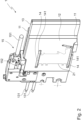
- Fig. 1 shows a perspective view of a heating element 1 according to the invention with a plastic profile 2 in contact with the contact plate.
- a plastic profile 2 is positioned in relation to the heating element 1 in such a way that a region of the front surface of the plastic profile 2 comes into contact with the heating element 1.
- the plastic profile 2 is heated or plasticized by the heating element 1 according to the method according to the invention.
- the Fig. 4, 5 and 6 The areas shown where material has been removed from the front side of the plastic profile 2, such as in the removals 25, 26, are shown in Fig. 1 not shown for the sake of clarity.
- the heating element 1 has a centrally or centrally arranged heating element 13.
- a contact plate 11 is arranged on each side of the plate-shaped heating element 13.
- the contact plates 11 are also plate-shaped.
- the back of the contact plates 11 lies flat on the heating element 13, which ensures good heat transfer from the heating element 13 to the contact plates 11.
- Two recesses 14 are milled into the contact plate 11, which is oriented towards the front in the illustration. These recesses 14 are referred to in connection with Figure 2
- the heating element 13 has two connections 131 oriented to the rear left, which serve to supply the heating element 13 with energy.
- the heating element 13 can be heated directly with electrical energy, for example. Alternatively, it is also possible to supply a liquid heating medium, such as hot water or oil, to the heating element 13 via the connections 131 and thus heat it.
- the connecting element 15 can be seen arranged at the upper edge of the heating element 13. This connecting element 15 serves to detachably connect the contact plates 11 to the heating element 13.
- the Pressure piece 152 is connected to the actuating lever 151. In the state shown, the pressure piece 152 is in a position in which it is moved relative to the heating element 13. In the state shown, the pressure piece 152 encloses part of the upper edge of the contact plates 11 in a shape complementary to that of the contact plates 11 and thereby presses them against the heating element 13.
- the pressure piece 152 has corresponding chamfered areas on its downward-facing side.
- the pressure piece 152 rests with its chamfered areas on the chamfered areas of the contact plates 11. Due to the bevels aligned at an angle of approximately 45° to the side surface of the heating element 13, when the pressure piece 152 is pressed vertically onto the contact plates 11, a force is created due to the wedge effect, which presses the contact plates 11 firmly against the surfaces of the heating element 13.
- the actuating lever 151 is moved upwards. This also moves the pressure piece 152 away from the heating element 13 and the contact plates 11.
- the connecting element 15 also comprises a holding piece 153 arranged on the lower edge of the heating element 13.
- the actuating lever 151 and the pressure piece 152 are then positioned downwards, which creates a positive connection and a frictional connection between the contact plates 11 and the heating element 13.
- the holding piece 153 also has areas with a bevel, whereby the bevel is oriented upwards here and serves as an insertion aid for the contact plates 11.
- the holding piece 153 is permanently connected to the heating element 13.
- Fig. 2 shows a perspective view of a heating element 1 according to the invention without plastic profile 2.
- the heating element 1 is off Fig. 1 without a plastic profile 2.
- the heating element 1 in Fig. 2 corresponds to heating element 1 in Fig. 1 , so that the description of heating element 1 from Fig. 1 also for Fig. 2 applies.
- the contact plate 11 facing forward is not covered by a plastic profile 2 and can therefore be seen in all details.
- the contact surface 12 of the front contact plate 11 faces forward.
- the contact surface 12 here has a homogeneous, smooth surface. In an alternative embodiment, however, the contact surface 12 can also have a regular contour, for example regularly arranged ribs. Such ribs can be used to enlarge the contact surface 12.
- the contact surface 12 is intended to come into contact with a plastic profile, in particular with the front side of a plastic profile.
- the outer contour 21 of the front side of a plastic profile 2 is drawn on the contact surface 12. This outer contour 21 is an auxiliary line only drawn in the illustration to facilitate understanding of the following description.
- the contact surface 12 is homogeneous and smooth; the outer contour 21 is not actually present or visible.
- Two recesses 14 are arranged in the contact surface 12, one in the upper area of the contact surface 12 and one near the lower edge. In the case shown, the two recesses 14 are pocket-shaped and are each delimited on the side facing away from the contact surface 12 by a base surface 141.
- the base surface 141 is set back from the contact surface 12 and is also flat here.
- the recesses 14 can also be designed in such a way that they completely penetrate the contact plate 11 and then have no bottom surface 141. In the case shown, the recesses 14 are milled out of the contact plate 11.
- the second contact plate 11 facing backwards cannot be seen.
- This second contact plate 11 is designed symmetrically to the first contact plate 11 facing forwards with respect to the center plane of the heating element 13.
- the second contact plate 11 facing backwards also has two recesses 14 which are arranged symmetrically to the two recesses 14 in the contact plate facing forwards.
- the two recesses 14 are arranged in such a way that their shape and position partially or partially border on the outer contour 21 of the plastic profile.
- Fig. 1 The plastic profile 2 shown has a flat visible surface at the top and bottom. There is also another visible surface curved to the front and right.
- the recesses 14 are shaped in such a way that their inner contour facing the outer contour 21 corresponds to the outer contour 21 of the plastic profile in these areas of the visible surfaces.
- edge areas of the plastic profile 2, where the visible surfaces are located are not touched by the heating element 1 according to the invention, these visible areas remain in a solid state, which results in a significantly improved surface quality of the subsequent welded connection.
- recesses 14 can also be arranged in other areas in the contact plate 11. The width of the Recesses 14, starting from their inner contour facing the outer contour 21 of the profile, are selected such that the area where the visible surfaces of the plastic profile 2 are located are definitely not touched by the contact plate 11. Furthermore, the distance also prevents the material in the area of the visible surfaces from heating up without contact, for example by heat radiation emanating from the contact plate 11.
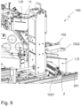
- FIG. 3 shows a perspective view of a device 100 according to the invention.
- a device 100 according to the invention serves to weld plastic profiles for producing frames, for example for doors or windows.
- the device 100 shown comprises a base plate 101 on which the other elements or assemblies of the device 100 are arranged.
- the base plate 101 is formed by a metal plate.
- the base plate 101 can also comprise other elements, such as a fastening element with which the device 100 is anchored at the production site or to a machine frame.
- One of the two holding elements 102 can be seen at the bottom left. This holding element 102 serves to clamp plastic profiles 2 for processing. Plastic profiles 2 are not shown in this view for the sake of clarity.
- the holding element 102 is designed to be movable and can be fed to the work steps with a plastic profile 2 clamped in it.
- the holding element 102 comprises two plates arranged vertically one above the other, between which a plastic profile 2 can be clamped.
- the holding element 102 is designed to be movable from front to back, into the plane of the drawing. This movable design allows the holding element 102 with the plastic profile to be fed, for example, to the heating element 1 shown in the background.
- the processing tool 103 can be seen, which is formed here by an assembly. The processing tool 103 is connected to the base plate 101 by the holder 1031 and fastened to it.
- the tool arm 1032 is arranged to be movable relative to the holder 1031.
- the tool arm 1032 can be moved vertically and horizontally in a direction parallel to the holder 1031 via actuators. This mobility allows the tool arm 1032 to be fed to a plastic profile 2 clamped in the holding element 102. Appropriate drives and guides are provided to achieve this mobility.
- the tool arm 1032 can also be designed to be movable in other spatial axes.
- a face milling cutter 1033 is arranged at the end of the tool arm 1032 facing to the rear left, which is intended to remove material from the front side of a plastic profile. The face milling cutter 1033 is thus the active element of the processing tool 103 for removing material.
- a further face milling cutter 1033 is arranged parallel to the face milling cutter 1033 shown. It is thus possible to use the tool arm 1032 to simultaneously machine two plastic profiles 2 that are to be welded together, with one face milling cutter 1033 coming into contact with an end face of each plastic profile.
- the device 100 naturally also has a second holding element 102, which is, however, hidden by other device parts in the illustration.
- the processing tool 103 in particular the tool arm 1032, is shown in a parked position. To remove material, the tool arm 1032 is moved into a working position so that the face milling cutters 1033 come into contact with the end faces of the plastic profiles clamped in the holding elements 102.
- the heating element 1 can be seen.
- the heating element 1 is also arranged so that it can move relative to the base plate 101.
- the heating element 1 is in the welding position. In this welding position, plastic profiles 2 clamped in the holding element 102 can be fed to the heating element 1 in a simple linear movement.
- the welding position of the heating element 1 is set so that the front sides of the plastic profiles 2 are correctly positioned in relation to the recesses 14 in the contact surface 12 of the heating element 1. For this correct positioning of the heating element 1 in relation to the front sides of the plastic profiles, see Fig. 1 and 2 and the associated description.
- the heating element 1 can be moved from the welding position shown to a rest position away from the plastic profiles.
- the heating element 1 When the heating element 1 is moved to the rest position, it is moved parallel to the large surface of the holder 1031 facing to the front left, with the heating element 1 moving to the top right. In the rest position, the heating element 1 is spaced apart from other components of the device 100, so that it is easily accessible for cleaning or replacing contact plates 11.
- the processing tool 103 When the device 100 is in operation, either only the processing tool 103 or the heating element 1 is in the working position or welding position. After the profiles of the holding elements 102 have been clamped, the processing tool 103 is first moved to the working position and then partially removes material from the front sides of the plastic profiles. The processing tool 103 is then moved to the parking position shown.
- the heating element 1 is then moved into the welding position shown and the plastic profiles are pressed against the contact surfaces 12 of the heating element 1 using the holding elements 102 and are thereby attached to the support surfaces plasticized.
- the heating element 1 is then also moved into its rest position, whereby there are no longer any device parts between the plasticized end faces of the plastic profiles 2. In this state, the clamped plastic profiles 2 are then pressed together and welded using the holding elements 102.
- Fig. 4 shows a schematic representation of a plastic profile 2 positioned relative to a heating element 1 according to the invention.
- Fig. 4 is a highly simplified representation and serves to illustrate the relationship between the dimensions of a plastic profile 2 and the position of two recesses 14 in a contact plate 11 of a heating element 1 according to the invention.
- the heating element 1 is presented here only as a section of a contact plate 11.
- the heating element 1 as for example Fig. 1 and Fig. 2 described, there are also further elements.
- two recesses 14 are arranged here, which break through the contact surface 12.
- the recesses 14 are pocket-shaped and are each delimited by a base surface 141 on the side facing away from the contact surface 12.
- the contact surface 12 and the base surfaces 141 are each flat here.
- the recesses 14 have a depth v from the contact surface 12 to the base surface 141. In the embodiment shown, the depth v is the same for the recesses 14.
- the two recesses 14 are arranged in the contact plate 11 at a distance s from one another. This distance s corresponds to the shortest distance between the side walls of the two recesses 14.
- Fig. 4 On the left side of Fig. 4 the right end of a plastic profile 2 is shown.
- the front side of the plastic profile 2 facing to the right is aligned at right angles to the length of the plastic profile 2.
- This embodiment allows for the simplest representation. In most cases, particularly in the manufacture of frames, the front side of the plastic profile 2 is arranged at a different angle to the length of the profile. In most cases, the plastic profile 2 is formed at a mitre so that the front side is usually arranged at a 45° angle to the length of the profile.
- material has already been removed from the front side or the front face of the plastic profile 2. In the illustration, facing upwards and downwards, the plastic profile 2 has surfaces on its long side that are visible after welding to the frame and thus form visible surfaces.
- the two removals 25, 26 Adjacent to the visible surfaces of the long sides of the plastic profile 2 facing upwards and downwards, there is a removal 25, 26. These removals 25, 26 were created by a previous removal of material by a processing tool. In the area of the removals 25, 26, material is therefore missing.
- the two removals 25, 26 have two boundary surfaces to the plastic profile 2 that are oriented at right angles to one another.
- the two inner boundary surfaces 251, 261 are those boundary surfaces of the removals 25, 26 that run parallel to the longitudinal direction of the plastic profile 2.
- the two inner boundary surfaces 251, 261 form the width h of the end face of the plastic profile 2 that remains after the material has been removed. The remaining end face is the end face that faces to the far right on the plastic profile 2 and is limited by the two removals 25, 26.
- This remaining end face with the width h is relevant for the interaction with the recesses arranged at a distance s in the contact plate 11 of the holding element shown opposite.
- the two cuts 25, 26 each have a depth t in the longitudinal direction of the plastic profile 2, which in the case shown is the same for both cuts 25, 26.
- the distance s between the two recesses 14 is exactly the same as the width h of the remaining front face of the plastic profile 2.
- To heat or melt the remaining front face of the plastic profile 2 it is moved from the state shown in the direction of the longitudinal direction of the plastic profile 2 to the contact plate.
- the remaining front face of the plastic profile 2 then lies congruently on the contact surface 12 between the two recesses 14, the dimensions of which correspond to the distance s.
- the depth v of the two recesses 14 is greater than the depth t of the two recesses 25, 26.
- the distance between the two side surfaces facing upwards and downwards in the illustration of the two opposite recesses 14 is greater than the total width of the plastic profile 2, which results from the sum of the width h and the width of the boundary surfaces 251, 261.
- This dimensioning ensures that contact between the plastic profile 2 and the contact plate 11 only occurs in the area provided for such contact between the width h and the distance s and that the areas of the front side of the plastic profile arranged outside the width h never come into contact with the contact plate 11.
- the areas adjacent to the width h and the distance s outside are so far apart that only very little radiant heat is transferred from the contact plate 11 to the plastic profile 2. This ensures that the material arranged adjacent to the visible surfaces of the plastic profile 2 is not softened by radiant heat emanating from the heating element 1.
- the plastic profile 2 has surfaces facing upwards and downwards, which later form visible surfaces. In the embodiment shown, these visible surfaces are aligned centrally to the width of the two recesses 14.
- the width of the recesses 14 is This refers to the dimension that runs from top to bottom in the drawing plane and forms an interruption in the contact surface 12.
- a central positioning of the visible surfaces in relation to the width of the recesses 14 is particularly advantageous, since the end of the visible surfaces facing to the right is thereby heated minimally by radiant heat from the contact plate 11.
- the position and width of the recesses 14 are adapted to the plastic profile 2 to be processed.
- the positioning of the visible surfaces of the plastic profile 2 can also be carried out off-center in relation to the width of the recesses 14.
- the contact plate 11 is relatively thick in relation to its height, in the direction of the dimension arrow to the width s, in particular more than three times as thick as the depth v of the recesses 14.
- the contact plate 11 can also be made significantly thinner in relation to its height.
- a thickness of the contact plate 11 that corresponds to the depth v is also suitable for the contact plate 11.
- the recesses 14 are then continuous and penetrate the entire contact plate 11.
- thinner contact plates 11 with pocket-shaped recesses 14, for example with a thickness that is 1.5 times as large as the depth v are also suitable for a heating element 1.
- Fig. 5 shows in views 5a and 5b the different results of melting at different distances s from recesses 14 in the heating element 1.
- Fig. 5a and Fig. 5b is only the one in Fig. 4
- the corresponding plastic profiles 2 are shown in a highly simplified manner. The illustrations show the appearance of the plastic profiles 2 after they have been brought into contact with the contact plate 11 of a heating element 1. The state shown is that in which the front surface of the plastic profiles 2 has already been melted.
- Fig. 4 and the corresponding description are the definition of the dimensions of the contact plate 11 and the plastic profile 2.
- Fig. 5a The result of the melting is shown for the case in which the distance s between two recesses 14 is greater than the width h of the remaining front surface of the plastic profile 2. During the melting carried out previously, the distance s was on both sides beyond the width h.
- the plastic profile 2 was pressed onto the contact plate 1, the material in this area was plasticized and partially pressed outwards. into the recesses 25, 26. The displaced material is thus absorbed by the recesses 25, 26. If the recesses 25, 26 are sufficiently large, the displaced material can remain there.
- the material in the ablations connects the plastic profiles 2 within the visible surface.
- Fig. 5b The result of melting is shown for the case where the distance s between two recesses 14 is smaller than the width h of the remaining front surface of the plastic profile 2.
- Fig. 5a was that in Fig. 5b The previously melted plastic profile 2 is brought into contact with a contact plate, in which the distance s between the two recesses 14 is smaller than the width h of the remaining front face of the plastic profile 2.
- the contact surface 12 between the two recesses 14 no longer rests against the plastic profile 2 over the entire width h. This means that the entire width h was not heated and the material located there was not plasticized everywhere.
- the protruding edge areas 27, 28 remain in the areas in which the contact surface 12 was not in contact with the front face.
- edge areas 27, 28 are not plasticized but are nevertheless softened by the heating of adjacent areas.
- the edge regions 27, 28 are pushed away and surrounded by plasticized material. This also creates a sufficiently strong connection point during welding in this embodiment.
- the edge regions 27, 28 can also be removed by a processing tool in a further removal step following the melting.
- Fig. 6 shows in views 6a to 6f schematic representations of process steps in the welding of plastic profiles 2. These views are shown in a highly simplified manner.
- Fig. 4 and 5 is the front face of the plastic profile shown 2 also in Fig. 6 aligned at right angles to the longitudinal direction of the plastic profile 2.
- the front surface can also be aligned at a different angle, for example at a 45° angle to the longitudinal direction of the plastic profile 2.
- Fig. 6a shows the state of a plastic profile 2 in which it is fed into the welding process.
- the front side of the plastic profile 2 facing to the right has been sawn off and is in a rough sawn state.
- the rough sawn surface is uneven.
- an excess was left on the plastic profile 2, so that the final dimension for welding must be set in the following steps.
- Fig. 6b shows the plastic profile 2 after the partial removal of material from the front side/face using a machining tool.
- the removals 25, 26 on the circumference were removed by the machining tool. These removals 25, 26 are intended to absorb material that swells outwards during welding.
- the machining tool removed material from the remaining face facing to the right, which is represented by the volume 29.
- the volume 29 By removing the volume 29, the previously rough-sawn surface was leveled and the angle of the face to the long side of the profile was adjusted.
- a machining tool design as a face milling cutter is particularly advantageous, since such a tool can machine large areas with very good surface quality quickly and precisely.
- Fig. 6c shows the plastic profile 2 during melting in contact with the contact plate 11 of the heating element 1.
- the state shown in this view corresponds to a state that is based on Fig. 4 after the plastic profile 2 and contact plate 11 are brought into contact.
- the plastic profile 2 is pressed against the hot contact plate 11.
- material on the remaining front side of the plastic profile 2 is melted and plasticized. This plasticized material swells outwards. If the plastic profile 2 is pressed against the contact plate 11 for a longer period of time, more and more material is displaced.
- the plastic profile 2 moves under contact pressure towards the contact plate 11. Material is continuously burned off the front surface, and the length of the plastic profile 2 is reduced in the process. This burn-off, which can be adjusted using the contact pressure and contact time, can be used to influence the final dimension of the plastic profile 2.
- Fig. 6d shows the state of the plastic profile 2 after an optional, second removal step of material.
- this second removal step the material created during melting in Fig. 6c Material displaced in the removals 25, 26 is removed again.
- the machining tool was also used for this optional removal step.
- no material was removed from the remaining face.
- Fig. 6e shows the plastic profile 2 during a second melting process.
- the plastic profile 2 is melted after the second removal step according to Fig. 6d analogous to Fig. 6c melted again.
- the Fig. 6d and 6e The steps shown are optional. However, these steps can be repeated several times to individually adjust the quality and strength of the welded joint.
- Fig. 6f shows the state of the plastic profile 2 after being pressed together and welded to another plastic profile 2 shown on the right.
- the material in the middle of the two plastic profiles 2 has fused together, creating a solid and continuous welded connection.
- the material in the border areas 211, 212 to the visible surfaces has not fused together. In this area, the material remained solid and not plasticized before being pressed together. For this reason, the surface quality in these border areas 211, 212 is particularly good, since in particular no bulging and no indentation occurred when the two plastic profiles 2 were brought together.
- the plastic profiles 2 When pressed together, the plastic profiles 2 are moved towards each other parallel to their longitudinal direction. Particularly favorable results when welding are achieved when the outer visible surfaces in the border areas 211, 212 abut one another without pressure being created between the visible surfaces in the border areas 211, 212 when pressed together. This ensures that no undesirable deformations occur here. However, the process also tolerates slight contact pressures between the visible surfaces in the border areas 211, 212 since the material here is in a non-plasticized, solid state that is suitable for absorbing and compensating for slight contact pressures.
- Fig. 7 shows a perspective view of a device 100 according to the invention with other components of a welding machine.
- the device 100 is made of Fig. 3 arranged on a welding machine, which comprises further components.
- the welding machine is based on a machine frame 200.
- This machine frame 200 is intended to carry one or more devices 100.
- One device 100 is shown as an example at the top left.
- One device 100 is required for each connection point between two plastic profiles 2.
- Four devices 100 are usually used to produce a frame, each device 100 of which creates a corner of the frame.
- Another term for device 100 is welding head; a welding machine with four devices 100 is often also referred to as a four-head welding machine.
- the machine frame 200 comprises a first guide 201, which runs from left to right in the illustration.
- the device 100 can be moved linearly along this first guide 201.
- elements for moving the device 100 are provided on the device 100 or on the first guide 201, such as motors and gears.
- a further device 100 is arranged on the first guide 201, which is not shown here for the sake of clarity.
- the second device 100 is also movable along the first guide 201, so that the two devices 100 can be moved towards and away from each other along the first guide 201. This mobility allows the plastic profiles 2 clamped in the devices 100 to be fed to the heating element 1, to the processing tool 103 and when pressed together after melting.
- a further, second guide is usually arranged, which is designed similarly or identically to the first guide 201.
- Two devices 100 are also arranged on the second guide so that they can move linearly relative to each other.
- a drive assembly 203 is arranged between the first guide 201 and the second guide. This drive assembly 203 is intended to move the two guides with the devices 100 mounted thereon towards each other.
- the drive assembly 203 is connected to the first guide 201 and the second guide (not shown). The movement of the two guides towards each other, made possible by the drive assembly 203, makes it possible to produce rectangular frames.
- the drive assembly 203 enables the plastic profiles 2 to be fed at right angles to the first guide 201 to the heating element 1, to the processing tool 103 and when pressed together after melting.
- the drive assembly 203 comprises the necessary guides, gear elements and motors to move two guides 201 towards and away from each other.
- the two devices arranged on a guide 201 are each moved towards each other, at the same time the two guides 201 arranged parallel to each other are also moved towards each other with the help of the drive assembly 203.
- a holding element 102 is shown in the open state on the device 100.
- the holding element 102 comprises a lower clamping plate 1021, which is triangular in this case, and an upper clamping plate 1022, which is also triangular.
- the plastic profile 2 is clamped between the two clamping plates 1021 and 1022.
- the upper clamping plate 1022 is moved upwards for the sake of clarity, so that the plastic profile 2 is not clamped or held in the state shown.
- the upper clamping plate 1022 is moved vertically downwards until it rests on the plastic profile 2.
- the plastic profile 2 rests on a heating element 1, which is currently in the welding position.
- a cleaning bar 1023 is arranged on the upper clamping plate 1022. This cleaning bar 1023 serves to remove dirt from the plastic profile, which can arise, for example, during processing by the processing tool 103.
- the cleaning bar 1023 has channels inside it that open into nozzles. Compressed air is connected to the cleaning bar 1023 so that, if desired, compressed air emerges from the nozzles and cleans the plastic profile 2 by blowing it off. This escaping compressed air is symbolized by lines 1024.
- a device 100 or a holding element 102 can also be designed without a cleaning bar 1023. In Fig. 7 the machining tool 103 is in its parking position and is largely concealed by other elements of the device 100.
- Fig. 8 shows a perspective view of a device 100 according to the invention with a heating element 1 in welding position and in rest position.
- Fig. 8 shows a device 100 from a different perspective than in Fig. 3 and Fig. 7 .
- the heating element 1 is shown in the welding position S at the bottom right and in the rest position R at the top left. In reality, the heating element 1 is only present once and is either in the welding position S or in the rest position R. In the welding position S shown at the bottom right, the heating element 1 is positioned so that the Plastic profile 2, such as Fig. 4 described in detail, can be moved to the heating element 1 for melting.
- the heating element 1 In the rest position R shown at the top left, the heating element 1 is spaced apart from other elements or assemblies of the device 100. The heating element 1 is thus easy to reach by the machine operator in the rest position R, so that cleaning or maintenance work on the heating element 1 can be carried out ergonomically in the rest position R. In the rest position R, it is also easy to change the contact plates 11 on the heating element 1. Even in Fig. 8 For the sake of clarity, only one holding element 102 is shown. As in Fig. 7 the upper clamping plate 1022 is moved away from the plastic profile 2. To fix or clamp the plastic profile 2, the upper clamping plate 1022 is moved vertically downwards towards the lower clamping plate 1021.
- the holding element 102 has a corresponding drive for this feed movement of the two clamping plates 1021, 1022.
- the device in Fig. 8 also has a Fig. 3 shown machining tool 103, which in Fig. 8 but is hidden by other elements of the device and is therefore not visible.
Landscapes
- Engineering & Computer Science (AREA)
- Mechanical Engineering (AREA)
- Physics & Mathematics (AREA)
- Thermal Sciences (AREA)
- Lining Or Joining Of Plastics Or The Like (AREA)
Description
- Die Erfindung betrifft ein Heizelement zur Erwärmung von Kunststoffprofilen vor deren Verbindung durch Schweißen umfassend zumindest eine Kontaktplatte mit einer zumindest einem Kunststoffprofil zugewandten Kontaktfläche, zumindest ein Erwärmungselement, welches in Wirkverbindung mit der Kontaktplatte steht, wobei die Kontaktplatte zumindest eine Ausnehmung aufweist, welche in der Kontaktfläche angeordnet ist und welche die Kontaktfläche unterbricht, wobei die Ausnehmung die Kontaktplatte komplett durchdringt oder die Ausnehmung eine Bodenfläche aufweist.
- Die Erfindung betrifft weiterhin eine Vorrichtung zum Verschweißen von Kunststoffprofilen mit einem Heizelement sowie ein Verfahren zum Verschweißen von Kunststoffprofilen, insbesondere unter Verwendung einer erfindungsgemäßen Vorrichtung.
- Die Vorrichtung ist geeignet zur Entfernung von Material außerhalb der Schweißzone eines oder mehrerer Kunststoffprofile.
- Die Herstellung von Rahmen, insbesondere für Fenster oder Türen aus Kunststoffprofilen, ist bekannt. Dabei werden unterschiedlich geformte Kunststoffprofile zunächst auf Maß und Gehrung gesägt und anschließend zu Rahmen verschweißt. Eine zuverlässige und kostengünstige Möglichkeit für eine solche Verschweißung ist das sogenannte Spiegelschweißen. Dabei werden die Stirnseiten der Kunststoffprofile zunächst an ein Heizelement, den Schweißspiegel, gedrückt, wobei das Material der Kunststoffprofile durch die vom Schweißspiel übertragene Wärme erweicht und aufgeschmolzen oder plastifiziert wird. Ist dieser Zustand erreicht, wird der Schweißspiegel entfernt und die an ihren Stirnseiten plastifizierten Kunststoffprofile aneinander gedrückt und somit verschweißt. Das plastifizierte Material eines Kunststoffprofils verbindet sich dabei mit dem plastifizierten Material eines anderen Kunststoffprofils. Dadurch entsteht eine durchgehende, langzeitstabile stoffschlüssige Verbindung zwischen zwei Kunststoffprofilen.
- Nachteilig an dieser Verbindungstechnik ist, dass beim Aneinanderdrücken der plastifizierten Stirnseiten der Kunststoffprofile ein Schweißwulst auf den äußeren Oberflächen der Verbindungsstelle der Kunststoffprofile entsteht. Dieser Schweißwulst wird durch beim Zusammendrücken verdrängtes Material gebildet. Der Schweißwulst führt zu einer unregelmäßigen Oberfläche der Verbindungsstelle und ist optisch unansehnlich auf Sichtflächen. Im Stand der Technik existieren bereits mehrere Ansätze, diesen Schweißwulst zu verhindern oder, falls dies nicht möglich ist, nach dem Verschweißen zu entfernen.
- Eine Möglichkeit einen Schweißwulst zu verhindern ist, angrenzend an die späteren Sichtflächen der Kunststoffprofile vor dem Schweißen Material zu entfernen. Dies kann beispielsweise durch Abfräsen eines Teils des Umfangs der Kunststoffprofile erfolgen. Durch dieses Entfernen von Material ist angrenzend an den Sichtbereich kein beim Schweißen plastifiziertes Material mehr vorhanden, was beim Zusammendrücken nach außen verdrängt wird. Dadurch kann ein Schweißwulst verhindert werden. Trotz dieser Entfernung von Material angrenzend an den Sichtbereich der Kunststoffprofile kann es dennoch vorkommen, dass auch im Bereich des entfernten Materials zumindest eine Teilplastifizierung erfolgt und beim Zusammendrücken oder Verschweißen der Kunststoffprofile immer noch ungewollte Verformungen im Sichtbereich auftreten. Beispielsweise werden die aneinanderstoßenden äußeren Oberflächen der Kunststoffprofile nach innen oder nach außen gedrückt.
-
US 7 328 734 B2 offenbart eine Maschine und ein Verfahren zum Zusammenschweißen von thermoplastischen Regenrinnen oder anderen Werkstücken. Eine stationäre und eine bewegliche Platte sind jeweils an einer Rahmenbaugruppe befestigt. Werkstückhalter und entsprechende Klemmen, die speziell zum Einspannen von Regenrinnen oder anderen Werkstücken konfiguriert sind, sind auf der feststehenden und der beweglichen Platte zusammen mit einer Abstandsplatte zum Positionieren und Halten der Enden zweier Werkstücke in einer Position zum Zusammenschweißen der Enden angeordnet. Ein Heizgerät ist vorgesehen, um die Enden der Werkstücke auf eine gewünschte Schweißtemperatur zu erwärmen, und eine Presse ist vorgesehen, um die verformten Enden der Werkstücke zum Schweißen zusammenzupressen und zu halten. -
WO 2013 132 406 A1 beschreibt ein Verfahren zum Schweißen von Profilelementen aus Kunststoff, insbesondere PVC, wobei zwei Profilelemente hergestellt werden, die so angeordnet sind, dass die jeweiligen zu verschweißenden Bereiche einander zugewandt sind. Anschließend wird in Übereinstimmung mit mindestens einem zu verschweißenden Bereich der Profilelemente eine Nut hergestellt. Nach dem Erwärmen der zu verschweißenden Bereiche werden diese miteinander verbunden, wobei die Profilelemente gegeneinander gepresst werden, um die zu verschweißenden Zonen in gegenseitigem Kontakt zu halten. Ein Aufnahmedrücker verhindert das Entstehen einer Schweißraupe auf der Oberfläche der Profilelemente. -
EP 0 139 350 A1 offenbart ein Widerstandsheizelement zum sterilen Verschweißen von thermoplastischen Rohren, wobei ein schmelzbares Signalmittel vorgesehen ist, das die Anzeige der ersten Verwendung des Heizelements ermöglicht. Das Signalmittel liefert hierzu ein elektrisches Signal, das vor der ersten Benutzung durch Schmelzen des Signalmittels eliminiert wird, wodurch die erste Benutzung eingeleitet werden kann. Wird das elektrische Signal bei erneuter Verwendung des Heizelements nicht erzeugt, ist der sterile Verbindungsapparat, in dem das Heizelement verwendet wird, so programmiert, dass er das Heizelement aussortiert. - Eine Aufgabe der vorliegenden Erfindung besteht darin, Lösungen vorzuschlagen, mit denen die Oberflächenqualität, insbesondere ein glattes und durchgehendes Erscheinungsbild beim Verschweißen von Kunststoffprofilen, weiter verbessert werden kann.
- Ein erfindungsgemäßes Heizelement ist in Anspruch 1 definiert.
- Erfindungsgemäß wird damit ein gegenüber dem Stand der Technik verbessertes Heizelement vorgeschlagen. Dieses Heizelement ist als Schweißspiegel für die Verwendung beim Spiegelschweißen vorgesehen. Die Erfindung wird im Zusammenhang mit dem Spiegelschweißen von Kunststoffprofilen beschrieben. Selbstverständlich kann ein erfindungsgemäßes Heizelement aber auch zum Erwärmen bzw. Verschweißen anderer Kunststoffteile, wie beispielsweise Platten oder Stäbe eingesetzt werden. Ebenso eignet sich ein erfindungsgemäßes Heizelement zum Verschweißen von Kunststoffprofilen, die für andere Anwendungen als den Fenster- oder Türenbau vorgesehen sind.
- Ein erfindungsgemäßes Heizelement umfasst zumindest eine Kontaktplatte, die dazu vorgesehen ist, mit einem zu verschweißenden Kunststoffprofil in Kontakt gebracht zu werden. Diese Kontaktplatte weist eine Kontaktfläche auf, die beim Verschweißen dem Kunststoffprofil zugewandt ist. Beim Verschweißen berührt die Kontaktfläche zumindest teilweise das Kunststoffprofil, insbesondere dessen Stirnseite oder Stirnfläche. Die Kontaktplatte mit der Kontaktfläche ist dazu vorgesehen, Material an der Stirnseite eines Kunststoffprofile zu erwärmen und zu plastifizieren. Üblicherweise umfasst ein Heizelement zur Herstellung von Rahmen aus Kunststoffprofilen zwei Kontaktplatten, die jeweils eine Kontaktfläche aufweisen. In diesem Fall mit zwei Kontaktflächen ist eine dieser Kontaktflächen einem ersten Kunststoffprofil zugewandt und die andere der Kontaktflächen einem zweiten, mit dem ersten zu verschweißenden Kunststoffprofil zugewandt. Weiterhin umfasst ein erfindungsgemäßes Heizelement zumindest ein Erwärmungselement. Das Erwärmungselement ist dazu vorgesehen, das Heizelement zu erhitzen. Dabei kann das Erwärmungselement beispielsweise elektrische Heizwendel aufweisen. Das Erwärmungselement kann aber auch durch andere Technologien erwärmt werden. Das Erwärmungselement steht in Wirkverbindung mit der Kontaktplatte. Unter Wirkverbindung ist hier zu verstehen, dass eine Wärmeübertragung zwischen Erwärmungselement und Kontaktplatte erfolgt. Eine gute Wärmeübertragung wird beispielsweise durch flächiges Aufliegen und Berühren von Kontaktplatte mit Erwärmungselement erreicht.
- Erfindungsgemäß weist die Kontaktplatte zumindest eine Ausnehmung auf, die in der Kontaktfläche angeordnet ist und die Kontaktfläche unterbricht. Beim Erwärmen einer Stirnseite eines Kunststoffprofils erfolgt im Bereich der Ausnehmung keine Berührung zwischen der Kontaktplatte und dem Kunststoffprofil. Dadurch erfolgt im Bereich der Ausnehmung auch keine Wärmeübertragung vom Heizelement auf das Kunststoffprofil. Die Bereiche des Kunststoffprofils, die beim Erwärmen der Ausnehmung gegenüber angeordnet sind, werden somit nicht oder nur in sehr geringem Maße erwärmt. Die Ausnehmung in der Kontaktfläche bewirkt somit, dass das zu verschweißende Kunststoffprofil bereichsweise nicht erwärmt wird. Dadurch verbleibt das Material des Kunststoffprofils in diesem Bereich deutlich fester als in dem Bereich, in dem die Kontaktfläche am Kunststoffprofil aufliegt und dieses plastifiziert. Günstiger Weise ist die Ausnehmung in der Kontaktfläche so angeordnet, dass sie beim Zusammenführen des Heizelementes mit dem Kunststoffprofil einer nach außen gewandten Sichtfläche des Kunststoffprofils gegenüberliegt. Damit wird der äußere Umfangsbereich des Kunststoffprofils nicht oder nur sehr wenig erwärmt, die Bereiche abseits der Sichtfläche, welche in Berührung mit der Kontaktfläche stehen, werden jedoch erwärmt und plastifiziert. Beim anschließenden Zusammendrücken und/oder Verschweißen des Kunststoffprofils verbleiben die der Ausnehmung gegenüber liegenden Bereiche in einem festen Zustand. Dadurch werden Verformungen beim Zusammendrücken in diesen Bereichen signifikant verringert. Dadurch, dass das Material in diesen Bereichen eine höhere Festigkeit aufweist, lässt es sich beim Zusammendrücken weniger leicht verformen und verbleibt somit formstabiler. Die Oberflächenqualität an der Verbindungsstelle des Kunststoffprofils mit einem anderen Kunststoffprofil wird somit deutlich verbessert. Erfindungsgemäß kann die Ausnehmung die Kontaktplatte komplett durchdringen. Die Ausnehmung kann beispielsweise aus der Kontaktplatte herausgefräst werden. Im Bereich der Ausnehmung ist in diesem Fall eine durchgehende Öffnung in der Kontaktplatte vorhanden. Alternativ kann die Ausnehmung taschenförmig ausgeführt sein. Eine solche taschenförmige Ausnehmung weist dann eine Bodenfläche auf, die die Ausnehmung auf der der Kontaktfläche abgewandten Seite begrenzt. Die Bodenfläche ist dieser Ausführungsform gegenüber der Kontaktfläche zurückversetzt, so dass die Bodenfläche bei der Zusammenführung mit dem Kunststoffprofile in einem Abstand zu diesem angeordnet ist und das Kunststoffprofil somit nicht berührt.
- Ein erfindungsgemäßes Heizelement mit zumindest einer Ausnehmung erwärmt ein Kunststoffprofil beim oder vor dem Verschweißen nur in bestimmten Bereichen. In anderen Bereichen wird das Kunststoffprofil nicht erwärmt und verbleibt in einem festen Zustand. Beim Verschweißen des Kunststoffprofils bleibt dieser Bereich, der sich in einem festeren Zustand befindet, formstabil und bewirkt so eine deutlich verbesserte Oberflächenqualität der Verbindungsstelle.
- Ein erfindungsgemäßes Heizelement kann als Teil einer Vorrichtung eingesetzt werden, mit der an einem oder mehreren Kunststoffprofilen Material entfernt wird, so dass außerhalb der Schweißstelle des oder der Kunststoffprofile eine Aussparung an Material vorliegt. Das Entfernen von Material außerhalb der Schweißstelle ist besonders günstig für eine gute Oberflächenqualität in diesem Bereich. Diese Vorgehensweise kann englischsprachig auch als "cut out of weldingzone" oder abgekürzt COW bezeichnet werden.
- Beim Erwärmen eines Kunststoffprofils durch das Heizelement liegt die Kontaktfläche auf der Stirnseite des Kunststoffprofils auf. Der Bereich, in dem Berührung zwischen Heizelement und Kunststoffprofil erfolgt, ist die Auflagefläche. Die zumindest eine Ausnehmung in der Kontaktfläche ist dazu vorgesehen, die Auflagefläche zu begrenzen. Durch diese Begrenzung wird das Kunststoffprofil nur bereichsweise stark erwärmt und plastifiziert. Im Bereich der Ausnehmung liegt die Kontaktplatte nicht an Kunststoffprofile auf, sodass hier keine Erwärmung erfolgt und das Kunststoffprofil in einem festen Zustand verbleibt.
- Bei einer bevorzugten Ausgestaltung des Vorschlags ist vorgesehen, dass die Kontaktfläche in sich homogen ausgeführt ist, wobei die Kontaktfläche plan ausgeführt ist oder eine regelmäßige Kontur, beispielsweise eine gerippte Oberfläche, aufweist. Die Kontaktfläche ist in sich homogen ausgeführt. Dies bedeutet, dass die Oberfläche regelmäßig über den gesamten Bereich der Kontaktfläche ausgeführt ist. Im einfachsten Fall ist die Kontaktfläche plan und glatt ausgeführt. Zur Erhöhung der Auflagefläche kann die Kontaktfläche jedoch auch konturiert ausgeführt sein. Eine solche konturierte Ausgestaltung kann beispielsweise durch regelmäßig auf der Kontaktfläche angeordnete Rippen geschaffen werden. Diese Rippen können dabei einen prismenartigen oder auch halbrunden Querschnitt aufweisen.
- Des Weiteren ist vorgesehen, dass die Ausnehmung eine Bodenfläche aufweist und die Bodenfläche plan ausgeführt ist oder eine regelmäßige Kontur aufweist. In der Ausführungsform, in der die Ausnehmung eine Bodenfläche aufweist, kann diese plan oder ebenfalls konturiert ausgeführt sein. Üblicherweise ist eine solche Bodenfläche plan ausgeführt. Eine solche plane Ausführung der Bodenfläche kann in einfacher Weise durch Herstellung der Ausnehmung durch einen Fräser erzeugt werden.
- In einer vorteilhaften Ausgestaltung ist vorgesehen, dass die Ausnehmung eine Bodenfläche aufweist und die Bodenfläche parallel zur Kontaktfläche verläuft. Auch diese Ausführungsform ist besonders einfach durch Fräsen herzustellen.
- Geschickter Weise ist vorgesehen, dass die Kontaktplatte und das Erwärmungselement als unterschiedliche Bauteile ausgeführt sind, wobei die Kontaktplatte zumindest teilweise flächig auf dem Erwärmungselement aufliegt, um eine gute Wärmeübertragung zwischen beiden Bauteilen sicherzustellen. In dieser Ausführungsform werden Kontaktplatte und Erwärmungselement durch unterschiedliche Bauteile gebildet. Dies hat den Vorteil, dass ein einziges Erwärmungselement mit mehreren unterschiedlich ausgeführten Kontaktplatten abwechselnd verbunden werden kann. Kontaktplatte und Erwärmungselement sind dabei so ausgeführt, dass eine möglichst große, flächige Berührung zwischen beiden Bauteilen vorliegt. Durch diese Berührung ist ein guter Wärmeübergang vom Erwärmungselement auf die Kontaktplatte sichergestellt. Günstiger Weise ist dazu das Erwärmungselement plattenförmig ausgeführt und die Kontaktplatte auf ihrer der Kontaktfläche abgewandten Seite formschlüssig passend zum Heizelement geformt.
- Des Weiteren ist günstiger Weise vorgesehen, dass die Form der Ausnehmung in einer Draufsicht auf die Kontaktfläche zumindest teilweise der Form der Außenkontur der Stirnseite eines zu verschweißenden Kunststoffprofiles entspricht. Die Form der Ausnehmung ist in dieser Ausführungsform so gewählt, dass sie in einer Draufsicht auf die Kontaktfläche zumindest zum Teil der Außenkontur des zu verschweißenden Kunststoffprofils entspricht. Im Bereich der Ausnehmung erfolgt keine oder nur eine sehr geringe Erwärmung des Kunststoffprofils. Diese geringe Erwärmung ist gerade an der Außenkontur, wo sich nach dem Verschweißen des Kunststoffprofils die Sichtfläche befindet, vorteilhaft, da das Material durch die geringe Erwärmung an dieser Stelle fest verbleibt und sich beim Verschweißen formstabil verhält. Bei einem Fensterrahmen befindet sich jedoch nicht im gesamten Umfangsbereich eines Kunststoffprofils eine Sichtfläche. Für eine gute Oberflächenqualität an der Sichtfläche ist es somit oftmals ausreichend, am Schweißspiegel eine oder mehrere Ausnehmungen so anzuordnen, dass diese beim Zusammenführen mit dem Kunststoffprofil an den Stellen angeordnet sind, wo sich später Sichtflächen befinden. An Stellen der Außenkontur des Kunststoffprofils, wo später keine Sichtflächen vorhanden sind, ist eine Ausnehmung nicht unbedingt erforderlich.
- Vorteilhafter Weise ist vorgesehen, dass die Innenkontur der Ausnehmung der Form des Außenumfangs eines zu verschweißenden Kunststoffprofiles entspricht und sich die Außenkontur der Ausnehmung eine größere Fläche umschließt als die Innenkontur der Ausnehmung. Die Ausnehmung wird in dieser Ausführungsform von einer Innenkontur und von einer Außenkontur begrenzt. Die Außenkontur der Ausnehmung ist dabei dem äußeren Rand der Kontaktplatte bzw. der Kontaktfläche zugewandt, die Innenkontur ist die Begrenzung der Ausnehmung, die dem äußeren Rand der Kontaktfläche abgewandt ist. Günstiger Weise ist die Form der Innenkontur der Ausnehmung gleich der Form des Außenumfangs des zu verschweißenden Kunststoffprofils. Beim Verschweißen wird das Heizelement so zum Kunststoffprofil positioniert, dass sich der Außenumfang des Kunststoffprofils deckungsgleich zur Innenkontur der Ausnehmung befindet. Unter Außenumfang des Kunststoffprofils ist dabei der Außenumfang zu verstehen, der die Stirnseite oder Stirnfläche des Kunststoffprofils umschließt. Die Ausnehmung erstreckt sich von deren Innenkontur, deren Form des Außenumfangs des Kunststoffprofils entspricht, nach außen bis zur Außenkontur der Ausnehmung. Beim Verschweißen ist die Ausnehmung somit gegenüber dem Bereich positioniert, welcher sich an den Außenumfang der Stirnfläche des Kunststoffprofils nach außen anschließt. Dadurch wird der Bereich außerhalb des Außenumfangs des Kunststoffprofils nicht vom Heizelement berührt und somit nicht direkt erwärmt. Auch in dieser Ausführungsform ist es meist ausreichend, wenn die von Innen- und Außenkontur definierte Ausnehmung nur bereichsweise den Außenumfang des Kunststoffprofils umschließt, nämlich dort wo später Sichtflächen vorhanden sind und eine besonders gute Oberflächengüte nach dem Verschweißen benötigt wird.
- Des Weiteren ist in dem Vorschlag vorteilhafter Weise vorgesehen, dass die Ausnehmung in einer Draufsicht auf die Kontaktfläche mehrere linear verlaufende Bereiche aufweist, welche an den Stellen der Kontaktfläche positioniert sind, die dazu vorgesehen sind, bei der Zusammenführung des Heizelementes mit einem zu verschweißenden Profil der mit einer Sichtfläche versehenen Außenkontur des Profils gegenüber zu liegen. In dieser Ausführungsform ist die Ausnehmung so gestaltet, dass sie nur bereichsweise dort angeordnet ist, wo beim Erwärmen Bereiche des Kunststoffprofils anliegen, die später eine Sichtfläche bilden. Üblicherweise sind diese Bereiche der Sichtflächen linear, wodurch auch die entsprechenden Bereiche der Ausnehmung linear ausgeführt sind. Selbstverständlich können diese Bereiche der Ausnehmung auch eine andere Form aufweisen, falls das Kunststoffprofil eine andere, nichtlineare Form an dieser Stelle aufweist.
- Erfindungsgemäß weist das Heizelement zumindest ein Verbindungselement auf, welches die Kontakplatte mit dem Erwärmungselement lösbar fest verbindet. Erfindungsgemäß werden Kontaktplatte und Heizelement durch unterschiedliche Bauteile gebildet, die über ein Verbindungselement einfach und zuverlässig miteinander verbunden und voneinander getrennt werden können. Eine solche Ausführungsform ermöglicht ein leichtes Austauschen der Kontaktplatte und somit eine einfache Anpassungszeit des Heizelementes an verschiedene Kunststoffprofile. Das Verbindungselement kann dabei als einfache Schraub- oder Steckverbindung ausgeführt sein. Weiterhin ist es möglich, dass am Erwärmungselement Führungen vorgesehen sind, in die die Kontaktplatte eingeschoben wird. Weiterhin sind verschiedene Ausführungsformen von Klemmvorrichtungen als Verbindungselement geeignet, welche die Kontaktplatte kraft- und/oder formschlüssig an das Erwärmungselement drücken und so für einen guten Wärmeübergang zwischen beiden Teilen sorgen.
- Des Weiteren ist vorgesehen, dass das Verbindungselement zumindest einen Betätigungshebel und zumindest ein Druckstück umfasst, wobei das Druckstück durch den Betätigungshebel zum Erwärmungselement hin- und von diesem wegbewegbar ausgeführt ist und das Druckstück zumindest teilweise in seiner Form komplementär zu einem Rand der Kontaktplatte ausgeführt ist. In dieser Ausführungsform ist das Verbindungselement als mehrteiliger Mechanismus ausgeführt. Das Verbindungselement umfasst dabei ein Druckstück, welches zumindest einen Bereich der Kontaktplatte und einen Bereich des Erwärmungselementes umfasst. Das Druckstück ist durch einen Betätigungshebel zum Erwärmungselement hin und von diesem wegbewegbar. Im vom Entfernungselement entfernten Zustand kann die Kontaktplatte entnommen oder eine Kontaktplatte zum Erwärmungselement hin bewegt werden. Anschließend wird der Betätigungshebel betätigt, wodurch das Druckstück zum Erwärmungselement hin bewegt wird und die Kontaktplatte dann formschlüssig mit dem Erwärmungselement verbindet. Ein solcher Mechanismus ist einfach zu bedienen und bietet eine stabile Verbindung zwischen Kontaktplatte und Erwärmungselement.
- In einer vorteilhaften Ausgestaltung ist vorgesehen, dass die Kontaktplatte aus einem Aluminiumbasiswerkstoff besteht und eine Beschichtung aufweist, die Teflon enthält. Als Werkstoff für die Kontaktplatte sind generell alle Werkstoffe geeignet, die eine gute Wärmeleitfähigkeit aufweisen. Durch eine gute Wärmeleitfähigkeit ist sichergestellt, dass die Wärme vom Erwärmungselement zügig auf das an der Kontaktfläche anliegende, zu verschweißende Kunststoffprofil übertragen wird. In der Praxis hat sich Aluminium oder ein Aluminiumsbasiswerkstoff als besonders geeignet für die Kontaktplatte herausgestellt. Selbstverständlich können aber auch andere gut wärmeleitfähige Werkstoffe, Metalle wie Nichtmetalle, als Werkstoff für eine Kontaktplatte dienen. Um zu verhindern, dass beim Verschweißen oder Erwärmen Kunststoffmaterial des Kunststoffprofils an der Kontaktplatte verbleibt, ist diese günstiger Weise mit einer Beschichtung versehen, die ein Anhaften des Kunststoffs verringert oder verhindert. In der Praxis haben sich Teflonbeschichtungen als besonders geeignet herausgestellt, da diese zuverlässig Haftung verhindern und zugleich temperaturstabil sind. Solche Teflonbeschichtungen können beispielsweise in Form einer Folie auf die Kontaktfläche aufgebracht werden. Es ist allerdings auch möglich eine Teflonbeschichtungen durch ein Spray oder durch Auftragen mit einem Pinsel oder einer Rolle auf der Kontaktfläche aufzubringen. Darüber hinaus sind auch andere Anti-Haftbeschichtungen, die auf anderen Materialien beruhen, geeignete Beschichtungen für die Kontaktplatte. In manchen Fällen wird auch gar keine Beschichtung benötigt, es ist ausreichend, die Oberfläche der Kontaktplatte entsprechend glatt zu polieren, um ein Anhaften von Kunststoffmaterial beim Erwärmen zu verhindern.
- Geschickter Weise ist vorgesehen, dass zwei Kontaktplatten vorgesehen sind, welche im Betriebszustand auf jeweils einer Seite des Erwärmungselementes angeordnet sind und welche bezogen auf die Mittelebene des Erwärmungselementes zueinander symmetrisch ausgeführt sind. In dieser Ausführungsform umfasst das Heizelement zwei Kontaktplatten. Diese Kontaktplatten sind auf gegenüberliegenden Seiten des Erwärmungselementes mit diesem verbunden. Diese Ausführungsform ist dazu vorgesehen, zwei Kunststoffprofile gleichzeitig zu erwärmen bzw. zu plastifizieren. Dieser Anwendungsfall ist der übliche Fall bei der Herstellung von Rahmen aus Kunststoffprofilen. Der Betriebszustand ist hier zu verstehen, dass das Heizelement einsatzbereit zur Erwärmung von Kunststoffprofilen ist. In diesem Betriebszustand sind die beiden Kontaktplatten mit dem Erwärmungselement verbunden. Für die Verbindung von zwei Kunststoffprofilen mit identischem Querschnitt sind die Kontaktplatten zur Mittelebene des Erwärmungselementes symmetrisch ausgeführt. Beide Kontaktplatten weisen Ausnehmungen auf, die so positioniert sind, dass bestimmte Bereiche des zu erwerbenden Kunststoffprofils nicht berührt werden.
- Des Weiteren ist günstiger Weise vorgesehen, dass die Kontaktplatte mehrteilig ausgeführt ist und zumindest einen Einsatz aufweist, der vom Rest der Kontaktplatte trennbar ausgeführt ist, wodurch eine Anpassung der Kontaktplatte durch Entnehmen oder Austauschen dieses Einsatzes an ein anders geformtes Kunststoffprofil ermöglicht wird. In dieser Ausführungsform wird eine Anpassbarkeit des Heizelementes an unterschiedliche Geometrien von Kunststoffprofilen nicht durch einen kompletten Austausch der Kontaktplatte, sondern durch einen Austausch eines Einsatzes der Kontaktplatte ermöglicht.
- Ein solcher Einsatz ist trennbar vom Rest der Kontaktplatte ausgeführt. Die Verbindung von Einsatz zum Rest der Kontaktplatte kann beispielsweise durch eine Steckverbindung erfolgen. Vorteilhaft bei dieser Ausführungsform ist, dass die zur Anpassung des Heizelementes benötigten Ersatzteile klein und kostengünstig sind.
- Vorteilhafter Weise ist vorgesehen, dass die Kontaktplatte zumindest ein beweglich ausgeführtes Element umfasst, wobei dieses beweglich ausgeführte Element über einen Einstellmechanismus bewegbar ausgeführt ist und die Kontaktplatte durch die Bewegung des beweglich ausgeführten Elementes an die Form eines Profilstückes anpassbar ist. In dieser Ausführungsform ist die Kontaktplatte durch ein beweglich ausgeführtes Element an unterschiedliche Kunststoffprofile anpassbar, ohne dass ein Austausch der gesamten oder eines Teils der Kontaktplatte erforderlich ist. Das beweglich ausgeführte Element kann über einen Einstellmechanismus in seiner Position verändert werden. Durch die Veränderung der Position des beweglich ausgeführten Elementes kann die Form und die Position der Ausnehmung in der Kontaktplatte variiert werden. Als Einstellmechanismus kann beispielsweise eine Gewindespindel vorgesehen werden, die mithilfe eines Steckschlüssels betätigt wird. Selbstverständlich können auch mehrere beweglich ausgeführte Elemente vorgesehen werden, um eine noch flexiblere Anpassung der Ausnehmung oder der Ausnehmungen zu ermöglichen.
- Die Aufgabe der Erfindung wird ebenfalls durch eine Vorrichtung zum Verschweißen von Kunststoffprofilen nach Anspruch 4 gelöst.
- Eine erfindungsgemäße Vorrichtung basiert auf einer Schweißvorrichtung oder einem Schweißaggregat nach dem Stand der Technik. Die erfindungsgemäße Vorrichtung baut auf einer Grundplatte auf, an welchem die anderen Bauteile der Vorrichtung fest oder beweglich angebracht sind. Die Vorrichtung ist dazu vorgesehen, Kunststoffprofile zu Rahmen, insbesondere zu Rahmen für Fenster oder Türen, zu verschweißen. Die Kunststoffprofile werden in Halteelemente eingespannt, welche sie während dem Verschweißen und während der anderen Bearbeitungsschritte halten. Eine erfindungsgemäße Vorrichtung weist zumindest zwei solche Halteelemente auf. Eine erfindungsgemäße Vorrichtung kann jedoch auch mehrere Halteelemente aufweisen. Ebenso ist es möglich zwei oder mehrere erfindungsgemäße Vorrichtungen zu einem Schweißautomaten zu kombinieren. Die Halteelemente sind dabei beweglich zur Grundplatte ausgeführt. Diese Beweglichkeit wird dazu benötigt, die Kunststoffprofile für die Bearbeitungsschritte mit dem Bearbeitungswerkzeug und dem Heizelement zuzustellen und auszurichten. Weiterhin wird die Beweglichkeit benötigt, um die Kunststoffprofile letztendlich beim Verschweißen zusammenzudrücken. Eine erfindungsgemäße Vorrichtung umfasst weiterhin ein Bearbeitungswerkzeug, welches dazu vorgesehen ist, Material an dem Kunststoffprofil oder den Kunststoffprofilen zu entfernen. Beispielsweise kann das Bearbeitungswerkzeug als Fräswerkzeug ausgeführt sein, welches spanend Teilbereiche der Stirnseite der Kunststoffprofile entfernt. Das Bearbeitungswerkzeug ist dazu vorgesehen, vor dem Verschweißen der Kunststoffprofile Teilbereiche der Stirnseite zu entfernen und somit der Bildung von Schweißwülsten entgegenzuwirken. Ein solches Entfernen von Material wird günstiger Weise dort vorgenommen, wo später, nach dem Verschweißen, Sichtflächen der Kunststoffprofile bzw. des Rahmens vorliegen.
- Eine erfindungsgemäße Vorrichtung umfasst weiterhin zumindest ein Heizelement nach einer der zuvor beschriebenen Ausführungsformen. Besonders vorteilhaft an einer erfindungsgemäßen Vorrichtung ist das Zusammenspiel zwischen dem Bearbeitungswerkzeug und dem erfindungsgemäßen Heizelement. Eine signifikante Verbesserung der Oberflächenqualität und des Erscheinungsbildes einer Verbindungsstelle zwischen zwei verschweißten Kunststoffprofilen kann dadurch erreicht werden, dass zunächst mit einem Bearbeitungswerkzeug ein Teil der zu verschweißen Fläche an der Stirnseite der Kunststoffprofile entfernt und anschließend diese bearbeitete Stirnseite selektiv, d.h. nur bereichsweise durch ein erfindungsgemäßes Heizelement erwärmt wird. Beim abschließenden Schweißvorgang entsteht dann kein ungewollter Schweißwulst, da im Sichtbereich kein Material mehr vorhanden ist, welches nach außen quellen kann. Gleichzeitig bleiben die Sichtflächen aufgrund der dort sehr viel geringeren Erwärmung durch das erfindungsgemäße Heizelement in einem festen Zustand und werden so beim Aneinanderdrücken nicht verformt.
- Des Weiteren ist in dem Vorschlag vorteilhafter Weise vorgesehen, dass das Bearbeitungswerkzeug als Fräswerkzeug ausgeführt ist, wobei das Bearbeitungswerkzeug zwischen einer Parkposition und eine Arbeitsposition beweglich ausgeführt ist. Ein Fräswerkzeug ist besonders geeignet als Bearbeitungswerkzeug, da durch Fräsen Material schnell und maß genau von den Kunststoffprofilen entfernt werden kann. Das Bearbeitungswerkzeug kann jedoch auch andersartig ausgeführt sein. Generell sind alle Technologien für ein Bearbeitungswerkzeug geeignet, die eine selektive Entfernung von Material an der Stirnseite oder angrenzend an die Stirnseite von Kunststoffprofilen ermöglichen. Beispielsweise kann ein Laser zur Entfernung von Material eingesetzt werden. Ein Laser hat zusätzlich den Vorteil, dass beim Abtrag von Material bereits Wärme in das Kunststoffprofil eingebracht wird, welche im nächsten Schritt zur Erwärmung oder zur Plastifizierung des Kunststoffprofiles eingesetzt werden kann. Darüber hinaus kann das Bearbeitungswerkzeug auch durch ein einfaches Messer, ein Schleifenwerkzeug, ein Stechwerkzeug oder ein Zangenwerkzeug gebildet werden. Unter Parkposition ist eine Position zu verstehen, in die das Bearbeitungswerkzeug gelegt wird, solange es nicht zur Entfernung von Material am Kunststoffprofil eingesetzt wird. Die Parkposition ist so gewählt, dass das Bearbeitungswerkzeug in dieser Position die anderen Komponenten der Vorrichtung nicht in ihrer Beweglichkeit behindert. Unter Arbeitsposition ist der Bereich zu verstehen, in dem sich das Bearbeitungswerkzeug beim Entfernen von Material am Kunststoffprofil befindet. Die Arbeitsposition ist somit nicht eine einzige Position, sondern ein Arbeitsbereich.
- Bei einer bevorzugten Ausgestaltung des Vorschlags ist vorgesehen, dass das Bearbeitungswerkzeug zumindest einen Stirnplanfräser umfasst und das Bearbeitungswerkzeug in der Arbeitsposition entlang zumindest zweier Raumachsen bewegbar ist, so dass das Bearbeitungswerkzeug dazu geeignet ist, entlang des gesamten Umfangs zumindest eines Kunststoffprofiles Material zu entfernen. In dieser Ausführungsform umfasst das Bearbeitungswerkzeug zumindest einen Stirnplanfräser, welcher Material am Kunststoffprofil entfernt. Ein Stirnplanfräser ermöglicht gleichzeitig ein Glätten und Planen der gesamten Stirnseite des Kunststoffprofiles und zusätzlich die selektive Entfernung von Material im Randbereich der Stirnfläche. Für diese selektive Entfernung im Randbereich wird das Bearbeitungswerkzeug um den stirnseitigen Umfang des Kunststoffprofiles herum bewegt. Dies wird dadurch ermöglicht, dass das Bearbeitungswerkzeug in seiner Arbeitsposition entlang zumindest zwei aufeinander senkrecht stehenden Raumachsen beweglich ausgeführt ist. Das Bearbeitungswerkzeug umfasst in dieser Ausführungsform auch die für diese Beweglichkeit erforderlichen Führungen und Antriebe.
- Des Weiteren ist vorgesehen, dass das Heizelement in seiner Ruheposition von anderen Komponenten der Vorrichtung beabstandet und gut für einen Bediener zugänglich angeordnet ist, wodurch ein Auswechseln oder eine Reinigung der Kontaktplatte in der Ruheposition möglich ist. Im Betrieb der Vorrichtung kann es vorkommen, dass am Heizelement durch das Erwärmen der Kunststoffprofile Kunststoffreste verbleiben, welche das Heizelement verschmutzen. In diesem Fall muss das Heizelement von Zeit zu Zeit gereinigt werden. Darüber hinaus muss meist zur Anpassung der Vorrichtung an die Verarbeitung an ein unterschiedliches Kunststoffprofil die Kontaktplatte des Heizelementes ausgewechselt werden. Sowohl für die Reinigung als auch für das Auswechseln der Kontaktplatte muss das Heizelement zumindest in seiner Ruheposition für einen Bearbeiter oder Maschinenbediener gut zugänglich und erreichbar sein. Dies kann dadurch erreicht werden, dass die Ruheposition des Heizelementes beabstandet von anderen Komponenten der Vorrichtung angeordnet ist. Ein günstiger Abstand liegt im Bereich von wenigen Zentimetern, beispielsweise im Bereich von 2-15 cm. Dieser Abstand ist geeignet, um die Kontaktplatte des Heizelementes mit der Hand erreichen zu können. Je größer der Abstand gewählt wird, desto ergonomischer kann die Vorrichtung bedient werden.
- In einer vorteilhaften Ausgestaltung ist vorgesehen, dass eine Temperaturwarnvorrichtung vorgesehen ist, welche zumindest in der Ruheposition des Heizelementes die Temperatur der Kontaktplatte misst und bei einer Temperatur, die bei Berührung der Kontaktplatte durch einen Bediener Verletzungen hervorruft, ein Warnsignal ausgibt. In dieser Ausführungsform ist eine Warnvorrichtung vorgesehen, die den Bediener vor Verbrennungen schützen soll. Das Heizelement weist im Betrieb der Vorrichtung üblicherweise eine Temperatur von mehr als 100 °C auf. Somit besteht beim Berühren des Heizelementes mit bloßer Hand erhebliche Verbrennungsgefahr. Die Temperaturwarnvorrichtung misst kontinuierlich die Temperatur des Heizelementes und damit der Kontaktplatte. Liegt diese gemessene Temperatur in einem Bereich, in dem Verletzungen erzeugt werden können, wird ein Warnsignal ausgegeben. Dieses Warnsignal kann optisch oder akustisch sein. Weiterhin kann eine Absperrung an der Vorrichtung vorgesehen werden, welche die warmen oder heißen Teile des Heizelementes physisch vor Zugriff sichert, solange sich deren Temperatur in einem Bereich befindet, in dem Verletzungen auftreten können.
- Die Aufgabe der Erfindung wird ebenfalls durch ein Verfahren zum Verschweißen von Kunststoffprofilen nach Anspruch 7 gelöst.
- Das erfindungsgemäße Verfahren wird bevorzugt mithilfe einer erfindungsgemäßen Vorrichtung durchgeführt. Das Verfahren kann jedoch auch mit anderen Hilfsmitteln oder Werkzeugen durchgeführt werden. Zunächst werden die zu verschweißenden Kunststoffprofile gesägt, wobei die Abmessungen der gesetzten Kunststoffprofile etwas größer sind als die geforderten Endabmessungen für den herzustellenden Rahmen. Anschließend werden im Verfahrensschritt A die Kunststoffprofile eingespannt, d. h. an der für das Verfahren verwendeten Vorrichtung fixiert. Die Einspannung erfolgt günstiger Weise in den beweglich ausgeführten Halteelementen einer erfindungsgemäßen Vorrichtung. In Verfahrensschritt B wird anschließend ein Teil der Stirnflächen der Kunststoffprofile durch ein Bearbeitungswerkzeug entfernt. Dabei kann zunächst über die gesamte Stirnfläche Material entfernt werden, wodurch die sägeraue Oberfläche der Kunststoffprofile geglättet und in den, für die Verschweißung erforderlichen Winkel gebracht wird. Anschließend wird durch das Bearbeitungswerkzeug im Umfangsbereich der Kunststoffprofile zusätzlich Material entfernt, insbesondere dort, wo nach dem Verschweißen Sichtflächen angeordnet sind. Durch Entfernen von Material in diesen Bereichen wird das Entstehen eines Schweißwulstes nach dem Verschweißen dort verhindert. Nach dem Entfernen von Material in Schritt B wird im darauffolgenden Verfahrensschritt C ein Aufschmelzen oder Plastifizieren zumindest eines Teils der Stirnseiten oder Stirnflächen der Kunststoffprofile vorgenommen. Dabei werden lediglich die Bereiche der Stirnseite der Kunststoffprofile aufgeschmolzen, die nach dem Entfernen B von Teilen der Stirnfläche durch das Bearbeitungswerkzeug verbleiben. Zum Aufschmelzen C wird ein erfindungsgemäßes Heizelement verwendet, welches zumindest eine Ausnehmung in jeder Kontaktfläche aufweist. Für das Aufschmelzen C sind an dem Heizelement zwei Kontaktplatten angeordnet, von denen jeweils eine mit einer Stirnseite eines zu verschweißenden Kunststoffprofils in Kontakt gebracht wird. Dieses In-Kontakt-Bringen wird dadurch erreicht, dass die Kunststoffprofile mithilfe der beweglich gelagerten Halteelemente in einer bestimmten Position an das Heizelement und die Kontaktplatten gedrückt werden. Diese Position ist so gewählt, dass die Ausnehmungen in den Kontaktflächen zumindest teilweise den beim Entfernen B bearbeiteten Bereichen der Kunststoffprofile gegenüberliegen. Dadurch wird erreicht, dass die bearbeiteten Bereiche, in denen Material entfernt wurde, beanstandet vom Heizelement verbleiben und somit weniger oder gar nicht erwärmt werden. Dies hat den bereits zuvor beschriebenen Effekt, dass das Material in diesen Bereichen, wo Material entfernt wurde, fest und formstabil verbleibt, wogegen das Material, welches an der Kontaktfläche des Heizelements anliegt, für die Verschweißung plastifiziert wird. Beim Aufschmelzen C wird somit nur lokal und selektiv aufgeschmolzen, manche Bereiche der Stirnseite der Kunststoffprofile werden dabei nicht aufgeschmolzen.
- Schließlich werden im Verfahrensschritt D die selektiv aufgeschmolzenen Stirnseiten der Kunststoffprofile aneinandergedrückt, wodurch das eigentliche Verschweißen der beiden Profile erfolgt. Das Zusammen- oder Aneinanderdrücken wird dabei bevorzugt durch eine Bewegung der Halteelemente vorgenommen, in denen die Kunststoffprofile eingespannt sind. Nach dem Zusammendrücken und Abkühlen liefert ein erfindungsgemäßes Verfahren eine Schweißverbindung zwischen zwei Kunststoffprofilen, welche keinen Schweißwulst aufweist. Gleichzeitig ist die Oberflächenqualität, insbesondere Ebenheit und ein optisch gutes Erscheinungsbild an den Stoßstellen, zwischen den beiden Profilen deutlich besser als beim Stand der Technik.
- Bevorzugt wird das erfindungsgemäße Verfahren genau in der beschriebenen Reihenfolge der Verfahrensschritte, alphabetisch geordnet von A bis D durchgeführt.
- Des Weiteren ist vorgesehen, dass in Verfahrensschritt C Aufschmelzen die verbleibende Stirnfläche der Kunststoffprofile eine Breite aufweist und die Kontaktflächen des Heizelementes zumindest zwei Ausnehmungen aufweisen, die in einem Abstand zueinander angeordnet sind, wobei die Breite dem Abstand entspricht und beim Aufschmelzen C die Breite deckungsgleich zum Abstand positioniert wird. In dieser Ausführungsform weist die nach dem Entfernen von Material in Schritt B verbleibende Stirnfläche der Kunststoffprofile eine Breite auf. Diese Breite ist selbstverständlich nicht nur auf eine Raumrichtung beschränkt, es können auch mehrere Breiten in verschiedenen Raumrichtungen verbleiben. Unter Breite ist diejenige Abmessung zu verstehen, die die Entfernung zwischen den Rändern der verbleibenden Stirnfläche definiert. In verschiedenen Richtungen können somit auch unterschiedlich große Breiten nach dem Entfernen von Material verbleiben. Die Kontaktflächen des Heizelementes weisen zumindest zwei Ausnehmungen auf, die die Kontaktfläche unterbrechen und die in einem Abstand zueinander angeordnet sind. Dieser Abstand zwischen den Ausnehmungen ist genauso gewählt, dass er der jeweiligen Breite der Stirnfläche der Kunststoffprofile entspricht. Beim Andrücken der Kunststoffprofile an die Kontaktflächen gerät die verbleibende Stirnfläche in Berührung mit der durch den Abstand definierten Oberfläche des Halteelementes zwischen zwei Ausnehmungen. Der Abstand wird dazu beim Verfahrensschritt C deckungsgleich zur Breite ausgerichtet. Für diese Ausrichtung oder Positionierung kann entweder das Heizelement entsprechend zu den Kunststoffprofilen hinbewegt oder in Umkehr die Kunststoffprofile, bevorzugt eingespannt in den Halteelementen, entsprechend zum Heizelement hin bewegt werden. Diese Positionierung zwischen Breite und Abstand kann bei Verwendung einer erfindungsgemäßen Vorrichtung beispielsweise durch eine Feineinstellung der Schweißposition des Halteelementes vorgenommen werden.
- In einer vorteilhaften Ausgestaltung ist vorgesehen, dass in Verfahrensschritt C Aufschmelzen die verbleibende Stirnfläche der Kunststoffprofile eine Breite aufweist und die Kontaktflächen des Heizelementes zumindest zwei Ausnehmungen aufweisen, die in einem Abstand zueinander angeordnet sind, wobei die Breite kleiner als der Abstand ist und beim Aufschmelzen C der Abstand so positioniert wird, dass er die Breite komplett überdeckt. Auch in dieser Ausführungsform weist die verbleibende Stirnfläche der Kunststoffprofile eine Breite auf. Für diese Breite gilt das zu der vorhergehenden Ausführungsform Beschriebene. Die Kontaktflächen weisen auch hier zumindest zwei Ausnehmungen auf, zwischen denen ein Abstand besteht. Auch für diesen Abstand gilt die Erklärung zu der zuvor beschriebenen Ausführungsform. In dieser alternativen Ausführungsform des Verfahrens ist jedoch der Abstand zwischen den Ausnehmungen größer gewählt als die Breite der verbleibenden Standfläche. Dadurch wird beim Aufschmelzen C die Gefahr minimiert, dass Breite und Abstand sich nicht genau überdecken und nicht der gesamte Bereich der verbleibenden Standfläche über dessen gesamte Breite aufgeschmolzen wird. Bei einem größeren Abstand wird dieser so zur Breite positioniert, dass er an beiden Seiten über die Breite hinaussteht und diese somit überdeckt. Durch diese Wahl der Abmessungen können Toleranzen bei der Bearbeitung der Profile und leichte Fehlpositionierungen beim Ausrichten der Kunststoffprofile zum Heizelement und umgekehrt ausgeglichen werden.
- Geschickter Weise ist vorgesehen, dass in Verfahrensschritt C Aufschmelzen die verbleibende Stirnfläche der Kunststoffprofile eine Breite aufweist und die Kontaktflächen des Heizelementes zumindest zwei Ausnehmungen aufweisen, die in einem Abstand zueinander angeordnet sind, wobei die Breite größer als der Abstand ist und beim Aufschmelzen C der Abstand so positioniert wird, dass er innerhalb der Breite am Kunststoffprofil aufliegt. Auch bei dieser alternativen Ausführungsform des Verfahrens ist die verbleibende Breite der Kunststoffprofile nach der Entfernung von Material und der Abstand zwischen zumindest zwei Ausnehmungen am Heizelement definiert wie in den beiden zuvor beschriebenen Ausführungsformen. Alternativ ist nun jedoch der Abstand zwischen zwei Ausnehmungen kleiner gewählt als die verbleibende Breite der Stirnfläche der Kunststoffprofile. Dadurch liegt die Kontaktfläche des Halteelementes nicht mehr auf der gesamten verbleibenden Stirnfläche mit der definierten Breite an. Im Verfahrensschritt C werden somit Randbereiche der verbleibenden Stirnfläche nicht mehr von der Kontaktfläche berührt und somit nicht direkt aufgeschmolzen. In diesen Randbereichen verbleibt ein nicht völlig plastifizierter Bereich an Material. Dieser verbleibende Bereich stört auch beim anschließenden Verschweißen oder Zusammendrücken nicht, da dieser Bereich zumindest aufgeweicht ist und sich beim Zusammendrücken entsprechend verformen lässt. Alternativ kann der verbleibende Bereich auch, wie weiter unten beschrieben, in einem zusätzlichen, vor dem Zusammendrücken durchgeführten Verfahrensschritt wieder entfernt werden. Vorteilhaft an dieser Ausführungsform, bei der der Abstand geringer als die Breite gewählt ist, ist, dass die Distanz zwischen dem aufgeschmolzenen Bereich zur außen am Rand der Kunststoffprofile angeordneten Sichtbereich noch größer ist als bei den zuvor beschriebenen Ausführungsformen. Dadurch wird der Außenumfang der Kunststoffprofile angeordnete Sichtbereich in noch geringerem Ausmaß erwärmt und verbleibt somit noch formstabiler. Dadurch kann die Oberflächenqualität im Sichtbereich der Schweißverbindung nochmals verbessert werden.
- In einer weiteren bevorzugten Ausführungsform ist vorgesehen, dass nach dem Aufschmelzen C und vor dem Zusammendrücken D folgende zusätzliche Schritte durchgeführt werden:
- B2. erneutes Entfernen eines Teils einer Stirnfläche der Kunststoffprofile und/oder zumindest teilweises Entfernen von durch das Aufschmelzen C verdrängtem Material von den Kunststoffprofilen durch ein Bearbeitungswerkzeug,
- C2. erneutes Aufschmelzen der nach dem Entfernen B2 verbleibenden Stirnflächen der Kunststoffprofile durch In-Kontakt-Bringen mit einem Heizelement nach einer der zuvor beschriebenen Ausführungsformen, wobei die Ausnehmungen der Kontaktflächen des Heizelementes so zu der Stirnseite positioniert werden, dass die Ausnehmungen den durch das Entfernen B2 bearbeiteten Bereichen der Kunststoffprofile gegenüberliegen.
- In dieser Ausführungsform werden zusätzlich zwei weitere Verfahrensschritte B2 und C2 nach dem Aufschmelzen C und vor dem Zusammendrücken D durchgeführt. Beim Aufschmelzen C werden die Stirnseiten der Kunststoffprofile gegen das Heizelement gedrückt, wobei das aufliegende Material an der Kontaktfläche plastifiziert wird. Dabei wird bereits aufgeschmolzenes Material nach außen verdrängt. Dadurch wird die Kontaktfläche der Kunststoffprofile gegenüber einen nicht aufgeschmolzenen Zustand vergrößert, was günstig für eine spätere, stabile Schweißverbindung ist. Nachteilig ist jedoch, dass Material auch in die Bereiche verdrängt wird, in denen später Sichtflächen vorliegen. Aus diesem Grund wird in der beschriebenen alternativen Ausführungsform des Verfahrens zunächst ein erstes Mal aufgeschmolzen, im Verfahrensschritt C, und anschließend mit dem Bearbeitungswerkzeug erneut ein Teil der Stirnfläche der Kunststoffprofile entfernt. Bevorzugt wird dabei das beim ersten Anschmelzen C in Richtung des Sichtbereiches verdrängte Material wieder entfernt. Das verwendete Material an anderen Bereichen wird hierbei jedoch nicht entfernt, wodurch die Größe der Oberfläche der Stirnseite der Kunststoffprofile nach dem zweiten Entfernungsschritt größer ist als nach dem ersten Entfernen B. Nach dem erneuten Entfernen B2 wird analog zum ersten Entfernen B ein zweites Mal aufgeschmolzen, nämlich im Verfahrensschritt C2. Das erneute Aufschmelzen C2 wird analog zum Aufschmelzen C durchgeführt und das Heizelement zu den Stirnflächen der Kunststoffprofile entsprechend positioniert. Durch das Einschieben der beiden optionalen Verfahrensschritte B2 und C2 wird die verschweißte Fläche zwischen den beiden Kunststoffprofilen vergrößert und somit die Festigkeit der Schweißverbindung verbessert. Gleichzeitig bleiben jedoch die Vorteile des erfindungsgemäßen Verfahrens bezüglich einer deutlich verbesserten Oberflächenqualität erhalten. Selbstverständlich können auch noch weitere, analog gestaltete Zwischenschritte des Aufschmelzens und Entfernens hinzugefügt werden. So ist es beispielsweise möglich, insgesamt drei Schritte des Aufschmelzens und drei Schritte des Entfernens hintereinander durchzuführen, bevor die Kunststoffprofile zusammengedrückt und verschweißt werden.
- Des Weiteren ist vorgesehen, dass nach dem Aufschmelzen C und vor dem Zusammendrücken D folgender zusätzlicher Schritt durchgeführt wird:
B2. erneutes Entfernen eines Teils einer Stirnfläche der Kunststoffprofile und/oder zumindest teilweises Entfernen von durch das Aufschmelzen C verdrängtem Material von den Kunststoffprofilen durch ein Bearbeitungswerkzeug. - In dieser Ausführungsform des Verfahrens wird lediglich ein Zwischenschritt B2 zwischen dem Aufschmelzen C und dem Zusammendrücken D durchgeführt. Nach dem Aufschmelzen C sind die Bereiche der Kunststoffprofile, in denen eine Berührung zwischen der Stirnseite und der Kontaktfläche erfolgte, erweicht oder plastifiziert. Dabei wurde auch bereits Material verdrängt, meist auch in die Bereiche, in denen später nach dem Zusammendrücken D eine Sichtfläche entstehen soll. Bei dieser Ausführungsform des Verfahrens wird in dem noch erwärmten Zustand nach dem Aufschmelzen C erneut Material im Bereich der Stirnflächen der Kunststoffprofile durch ein Bearbeitungswerkzeug entfernt. Bevorzugt wird dabei nur das Material entfernt, welches in den Bereich der Sichtfläche verdrängt wurde. Dieses erneute Entfernen von Material B2 wird durchgeführt, solange sich das Material noch in einem erweichten oder plastifizierten Zustand befindet. Eine solche Entfernung von erweichtem Material ist beispielsweise mit einem als Fräswerkzeug ausgeführten Bearbeitungswerkzeug möglich. Dieses erneute Entfernen von Material B2 wird dabei zügig durchgeführt, sodass das Material beim Entfernen nicht wesentlich abkühlt und in dem erweichten Zustand verbleibt. Nach dem erneuten Entfernen von Material B2 werden die Stirnseiten der Kunststoffprofile dann ohne erneutes Aufschmelzen zusammengedrückt und verschweißt. Zu diesem Zeitpunkt befindet sich das Material im Bereich der Stirnflächen immer noch in einem erweichten, plastifizierten Zustand. Auf diese Weise kann die Oberflächenqualität in den Sichtbereichen durch das erneute Entfernen von Material verbessert werden und gleichzeitig wird die Prozesszeit für das Verschweißen der Kunststoffprofile nur unwesentlich, nämlich um den zweiten Entfernungsschritt B2, verlängert. Ein zweiter Schritt des Aufschmelzens nach dem zweiten Entfernungsschritt B2 wird in dieser Ausführungsform des Verfahrens nicht benötigt.
- In diesem Zusammenhang wird insbesondere darauf hingewiesen, dass alle im Bezug auf die Vorrichtung beschriebenen Merkmale und Eigenschaften aber auch Verfahrensweisen sinngemäß auch bezüglich der Formulierung des erfindungsgemäßen Verfahrens übertragbar und im Sinne der Erfindung einsetzbar und als mitoffenbart gelten. Gleiches gilt auch in umgekehrter Richtung, das bedeutet, nur im Bezug auf das Verfahren genannte, bauliche also vorrichtungsgemäße Merkmale können auch im Rahmen der Vorrichtungsansprüche berücksichtigt und beansprucht werden und zählen ebenfalls zur Offenbarung.
- In den Zeichnungen ist die Erfindung in Ausführungsbeispielen schematisch dargestellt. Es zeigen:
- Fig. 1
- eine perspektivische Ansicht eines erfindungsgemäßen Heizelementes mit einem mit der Kontaktplatte in Berührung stehenden Kunststoffprofil,
- Fig. 2
- eine perspektivische Ansicht eines erfindungsgemäßes Heizelement ohne Kunststoffprofil,
- Fig. 3
- eine perspektivische Ansicht einer erfindungsgemäßen Vorrichtung,
- Fig. 4
- eine schematische Darstellung eines zu einem erfindungsgemäßen Heizelement positionierten Kunststoffprofils,
- Fig. 5
- in den Ansichten 5a und 5b die unterschiedlichen Ergebnisse des Anschmelzens bei unterschiedlichen Abständen von Ausnehmungen im Heizelement,
- Fig. 6
- in den Ansichten 6a bis 6f schematische Darstellungen von Verfahrensschritten beim Verschweißen von Kunststoffprofilen,
- Fig. 7
- eine perspektivische Ansicht einer erfindungsgemäßen Vorrichtung mit weiteren Komponenten einer Schweißmaschine,
- Fig. 8
- eine perspektivische Ansicht einer erfindungsgemäßen Vorrichtung mit einem Heizelement in Schweißposition und in Ruheposition.
- In den Figuren sind gleiche oder einander entsprechende Elemente jeweils mit den gleichen Bezugszeichen bezeichnet und werden daher, sofern nicht zweckmäßig, nicht erneut beschrieben. Die in der gesamten Beschreibung enthaltenen Offenbarungen sind sinngemäß auf gleiche Teile mit gleichen Bezugszeichen bzw. gleichen Bauteilbezeichnungen übertragbar. Auch sind die in der Beschreibung gewählten Lageangaben, wie z.B. oben, unten, seitlich usw. auf die unmittelbar beschriebene sowie dargestellte Figur bezogen und sind bei einer Lageänderung sinngemäß auf die neue Lage zu übertragen. Weiterhin können auch Einzelmerkmale oder Merkmalskombinationen aus den gezeigten und beschriebenen unterschiedlichen Ausführungsbeispielen für sich eigenständige, erfinderische oder erfindungsgemäße Lösungen darstellen.
-
Fig. 1 zeigt eine perspektivische Ansicht eines erfindungsgemäßen Heizelementes 1 mit einem mit der Kontaktplatte in Berührung stehenden Kunststoffprofil 2. In der Darstellung ist ein Kunststoffprofil 2 so zum Heizelement 1 positioniert, dass ein Bereich der Stirnfläche des Kunststoffprofils 2 in Berührung mit dem Heizelement 1 kommt. In der dargestellten Position wird das Kunststoffprofil 2 von Heizelement 1 gemäß dem erfindungsgemäßen Verfahren erwärmt bzw. plastifiziert. Die in denFig. 4, 5 und6 dargestellten Bereiche, an denen an der Stirnseite des Kunststoffprofils 2 Material entfernt wurde, wie beispielsweise in den Abtragungen 25, 26, sind inFig. 1 der Übersichtlichkeit halber nicht dargestellt. Selbstverständlich können aber auch Kunststoffprofile 2 mit an der Stirnseite entferntem Material, wie durch die Abtragungen inFig. 4, 5 und6 dargestellt, entsprechend der Darstellung inFig. 1 an das Heizelement 1 herangeführt und mit diesem in Berührung gebracht werden. Weitere Bauteile oder Baugruppen, welche für die praktische Positionierung des Kunststoffprofils 2 zum Heizelement 1 benötigt werden, sind in dieser Ansicht der Übersichtlichkeit halber nicht dargestellt. Das Heizelement 1 weist ein zentral oder mittig angeordnetes Erwärmungselement 13 auf. Auf beiden Seiten des plattenförmig ausgeführten Erwärmungselementes 13 ist jeweils eine Kontaktplatte 11 angeordnet. Auch die Kontaktplatten 11 sind plattenförmig ausgeführt. Die Kontaktplatten 11 liegen mit ihrer Rückseite flächig am Erwärmungselement 13 auf, wodurch ein guter Wärmeübergang vom Erwärmungselement 13 zu den Kontaktplatten 11 sichergestellt ist. In der in der Darstellung nach vorne orientierten Kontaktplatte 11 sind zwei Ausnehmungen 14 eingefräst. Auf diese Ausnehmungen 14 wird in Zusammenhang mitFigur 2 näher eingegangen. Das Erwärmungselement 13 weist nach links hinten orientiert zwei Anschlüsse 131 auf, welche zur Versorgung des Erwärmungselementes 13 mit Energie dienen. Dabei kann das Erwärmungselement 13 beispielsweise direkt mit elektrischer Energie erhitzt werden. Alternativ ist es aber auch möglich, über die Anschlüsse 131 ein flüssiges Heizmittel, wie beispielsweise heißes Wasser oder Öl dem Erwärmungselement 13 zuzuführen und dieses so zu erwärmen. In der Darstellung ist am oberen Rand des Erwärmungselementes 13 angeordnet das Verbindungselement 15 zu sehen. Dieses Verbindungselement 15 dient dazu, die Kontaktplatten 11 lösbar fest mit dem Erwärmungselement 13 zu verbinden. Das Druckstück 152 ist mit dem Betätigungshebel 151 verbunden. Im dargestellten Zustand befindet sich das Druckstück 152 in einer zum Erwärmungselement 13 in bewegter Position. Im dargestellten Zustand umschließt das Druckstück 152 formkomplementär einen Teil des oberen Randes der Kontaktplatten 11 und drückt diese dadurch an das Erwärmungselement 13. Ein Teil des oberen Randes der Kontaktplatten 11 ist abgeschrägt bzw. mit einer Fase versehen. Das Druckstück 152 weist auf seiner nach unten gewandten Seite entsprechende mit einer Fase versehene Bereiche auf. Das Druckstück 152 liegt mit seinen mit einer Fase versehenen Bereichen auf den mit Fasen versehenen Bereichen der Kontaktplatten 11 auf. Durch die in einem Winkel von ca. 45° zur Seitenfläche des Erwärmungselementes 13 ausgerichteten Fasen entsteht beim vertikalen Aufdrücken des Druckstückes 152 auf die Kontaktplatten 11 aufgrund der Keilwirkung eine Kraft, die die Kontaktplatten 11 fest an die Oberflächen des Erwärmungselementes 13 drückt. Um die Kontaktplatten 11 vom Erwärmungselement 13 zu trennen, wird der Betätigungshebel 151 nach oben bewegt. Dadurch wird auch das Druckstück 152 vom Erwärmungselement 13 und den Kontaktplatten 11 wegbewegt. Der Formschluss zwischen den Teilen wird dabei aufgehoben, sodass die Kontaktplatten 11 dann vom Erwärmungselement 13 entfernt werden können. Das Verbindungselement 15 umfasst weiterhin einen unteren Rand des Erwärmungselementes 13 angeordnetes Haltestück 153. Bei der Verbindung der Kontaktplatten 11 mit dem Erwärmungselement 13 durch das Verbindungselement 15 wird zunächst der untere Rand der Kontaktplatten in das Haltestück 153 eingeführt. Anschließend wird der Betätigungshebel 151 und das Druckstück 152 nach unten positioniert, wodurch ein Formschluss und ein Kraftschluss zwischen den Kontaktplatten 11 und dem Erwärmungselement 13 entsteht. Auch das Haltestück 153 weist Bereiche mit einer Fase auf, wobei die Fase hier nach oben orientiert ist und als Einführhilfe für die Kontaktplatten 11 dient. Das Haltestück 153 ist dauerhaft fest mit dem Erwärmungselement 13 verbunden. -
Fig. 2 zeigt eine perspektivische Ansicht eines erfindungsgemäßen Heizelementes 1 ohne Kunststoffprofil 2. InFig. 2 ist das Heizelement 1 ausFig. 1 ohne ein Kunststoffprofil 2 dargestellt. Das Heizelement 1 inFig. 2 entspricht dem Heizelement 1 inFig. 1 , so dass die Beschreibung zum Heizelement 1 ausFig. 1 auch fürFig. 2 gilt. InFig. 2 ist die nach vorne gewandte Kontaktplatte 11 nicht von einem Kunststoffprofil 2 verdeckt und somit in allen Details zu erkennen. Nach vorne gewandt ist die Kontaktfläche 12 der vorderen Kontaktplatte 11. Die Kontaktfläche 12 weist hier eine homogene, glatte Oberfläche auf. In einer alternativen Ausführungsform kann die Kontaktfläche 12 jedoch auch eine regelmäßige Kontur aufweisen, beispielsweise regelmäßig angeordnete Rippen. Solche Rippen können zur Vergrößerung der Kontaktfläche 12 eingesetzt werden. Die Kontaktfläche 12 ist dazu vorgesehen, mit einem Kunststoffprofil, insbesondere mit der Stirnseite eines Kunststoffprofils in Berührung oder Kontakt zu kommen. Auf der Kontaktfläche 12 ist die Außenkontur 21 der Stirnseite eines Kunststoffprofils 2 eingezeichnet. Diese Außenkontur 21 ist eine nur in der Darstellung eingezeichnete Hilfslinie um das Verständnis der folgenden Beschreibung zu erleichtern. Die Kontaktfläche 12 ist homogen und glatt ausgeführt, die Außenkontur 21 ist in Realität nicht vorhanden oder zu sehen. In der Kontaktfläche 12 sind zwei Ausnehmungen 14 angeordnet, eine im oberen Bereich der Kontaktfläche 12 und eine in der Nähe des unteren Randes. Im dargestellten Fall sind die beiden Ausnehmungen 14 taschenförmig ausgeführt und werden auf ihrer der Kontaktfläche 12 abgewandten Seite durch jeweils eine Bodenfläche 141 begrenzt. Die Bodenfläche 141 ist gegenüber der Kontaktfläche 12 zurückversetzt und hier ebenfalls plan ausgeführt. Alternativ können die Ausnehmungen 14 auch so ausgeführt sein, dass sie die Kontaktplatte 11 komplett durchdringen und dann keine Bodenfläche 141 aufweisen. Im dargestellten Fall sind die Ausnehmungen 14 aus der Kontaktplatte 11 herausgefräst. InFig. 1 ist die nach hinten gewandte zweite Kontaktplatte 11 nicht zu erkennen. Diese zweite Kontaktplatte 11 ist bezogen auf die Mittelebene des Erwärmungselementes 13 symmetrisch zu der nach vorne gewandten ersten Kontaktplatte 11 ausgeführt. Somit weist auch die zweite, nach hinten gewandte Kontaktplatte 11 zwei Ausnehmungen 14 auf, die symmetrisch zu den beiden Ausnehmungen 14 in der nach vorne gewandten Kontaktplatte angeordnet sind. - Die beiden Ausnehmungen 14 sind so angeordnet, dass ihre Form und Position teilweise bzw. bereichsweise an die Außenkontur 21 des Kunststoffprofiles angrenzen. Das in
Fig. 1 eingezeichnete Kunststoffprofil 2 weist nach oben und nach unten jeweils eine plan ausgeführte Sichtfläche auf. Weiterhin ist eine nach vorne rechts gekrümmte weitere Sichtfläche vorhanden. Die Ausnehmungen 14 sind so geformt, dass deren in Richtung zur Außenkontur 21 gewandte Innenkontur in diesen Bereichen der Sichtflächen der Außenkontur 21 des Kunststoffprofiles entspricht. Durch eine solche Anordnung der Ausnehmungen 14 wird erreicht, dass das Kunststoffprofil 2 im Bereich von dessen Sichtflächen nicht durch die Kontaktplatte 11 erwärmt wird. Der Rest der Stirnseite des Kunststoffprofiles 2, welcher von der Außenkontur 21 umschlossen wird, wird jedoch von der Kontaktplatte 11 berührt und erwärmt. Dadurch, dass die Randbereiche des Kunststoffprofiles 2, dort, wo sich die Sichtflächen befinden, nicht von dem erfindungsgemäßen Heizelement 1 berührt werden, verbleiben eben diese Sichtbereiche in einem festen Zustand, wodurch sich eine deutlich verbesserte Oberflächenqualität der späteren Schweißverbindung ergibt. Selbstverständlich können Ausnehmungen 14 auch noch in anderen Bereichen in der Kontaktplatte 11 angeordnet werden. Die Breite der Ausnehmungen 14, ausgehend von deren der Außenkontur 21 des Profils zugewandten Innenkontur ist so gewählt, dass der Bereich, wo sich die Sichtflächen des Kunststoffprofiles 2 befinden, sicher nicht von der Kontaktplatte 11 berührt werden. Weiterhin wird durch den Abstand auch verhindert, dass sich das Material im Bereich der Sichtflächen berührungslos, beispielsweise durch Wärmestrahlung ausgehend von der Kontaktplatte 11 erwärmt. -
Fig. 3 zeigt eine perspektivische Ansicht einer erfindungsgemäßen Vorrichtung 100. Eine erfindungsgemäße Vorrichtung 100 dient dazu, Kunststoffprofile zur Herstellung von Rahmen, beispielsweise für Türen oder Fenster, zu verschweißen. Die dargestellte Vorrichtung 100 umfasst dazu eine Grundplatte 101, auf dem die weiteren Elemente oder Baugruppen der Vorrichtung 100 angeordnet sind. Im dargestellten Fall wird die Grundplatte 101 durch eine Metallplatte gebildet. Die Grundplatte 101 kann zusätzlich aber auch noch weitere Elemente umfassen, wie beispielsweise ein Befestigungselement, mit welchem die Vorrichtung 100 am Produktionsort oder an einem Maschinengestell verankert wird. Links unten ist eines der beiden Halteelemente 102 zu sehen. Dieses Halteelement 102 dient dazu, Kunststoffprofile 2 für die Verarbeitung einzuspannen. Kunststoffprofile 2 sind in dieser Ansicht der Übersichtlichkeit halber nicht dargestellt. Das Halteelement 102 ist beweglich ausgeführt und kann mit einem darin eingespannten Kunststoffprofil 2 den Arbeitsschritten zugeführt werden. In der dargestellten Ausführungsform umfasst das Halteelement 102 zwei vertikal übereinander angeordnete Platten, zwischen die ein Kunststoffprofil 2 eingespannt werden kann. In der dargestellten Ausführungsform ist das Halteelement 102 von vorne nach hinten, in die Zeichnungsebene hinein, beweglich ausgeführt. Durch diese bewegliche Ausführung kann das Halteelement 102 mit dem Kunststoffprofil beispielsweise dem im Hintergrund dargestellten Heizelement 1 zugeführt werden. Auf der rechten Seite in der Darstellung ist das Bearbeitungswerkzeug 103 zu sehen, welches hier von einer Baugruppe gebildet wird. Das Bearbeitungswerkzeug 103 ist durch den Halter 1031 mit der Grundplatte 101 verbunden und an diesen befestigt. Beweglich zu dem Halter 1031 ist der Werkzeugarm 1032 angeordnet. Der Werkzeugarm 1032 kann in vertikaler Richtung und horizontal in einer Richtung parallel zum Halter 1031 über Aktoren bewegt werden. Über diese Beweglichkeit kann der Werkzeugarm 1032 zu einem im Halteelement 102 eingespannten Kunststoffprofil 2 zugestellt werden. Zur Realisierung dieser Beweglichkeit sind entsprechende Antriebe und Führungen vorgesehen. Selbstverständlich kann der Werkzeugarm 1032 auch in weiteren Raumachsen beweglich ausgeführt sein. An dem nach links hinten gewandten Ende des Werkzeugarms 1032 ist ein Stirnplanfräser 1033 angeordnet, der dazu vorgesehen ist, Material an der Stirnseite eines Kunststoffprofils zu entfernen. Der Stirnplanfräser 1033 ist somit das aktive Element des Bearbeitungswerkzeugs 103 für die Entfernung von Material. - Auf der in der Zeichnungsansicht nach hinten gewandten Seite des Werkzeugarmes 1032 ist parallel zu den dargestellten Stirnplanfräser 1033 ein weiterer Stirnplanfräser 1033 angeordnet. Somit ist es möglich, mit dem Werkzeugarm 1032 zwei miteinander zu verschweißende Kunststoffprofile 2 gleichzeitig zu bearbeiten, wobei jeweils ein Stirnplanfräser 1033 in Kontakt mit einer Stirnfläche jedes Kunststoffprofils kommt. Zur Einspannung und Führung weist die Vorrichtung 100 selbstverständlich auch ein zweites Halteelement 102 auf, welches in der Darstellung jedoch durch andere Vorrichtungsteile verdeckt ist. In der Darstellung ist das Bearbeitungswerkzeug 103, insbesondere der Werkzeugarm 1032 in einer Parkposition dargestellt. Zur Entfernung von Material wird der Werkzeugarm 1032 in eine Arbeitsposition bewegt, sodass die Stirnplanfräser 1033 in Kontakt mit den Stirnseiten der in den Halteelementen 102 eingespannten Kunststoffprofile kommen.
- In der Darstellung hinten links ist das Heizelement 1 zu sehen. Auch das Heizelement 1 ist beweglich zur Grundplatte 101 angeordnet. In der Darstellung in
Fig. 3 befindet sich das Heizelement 1 in der Schweißposition. In dieser Schweißposition können im Halteelement 102 eingespannte Kunststoffprofile 2 in einer einfachen linearen Bewegung dem Heizelement 1 zugestellt werden. Die Schweißposition des Heizelementes 1 ist dabei so eingestellt, dass die Stirnseiten der Kunststoffprofile 2 richtig zu den Ausnehmungen 14 in der Kontaktfläche 12 des Heizelementes 1 positioniert sind. Zu dieser richtigen Positionierung von Heizelement 1 zu den Stirnseiten der Kunststoffprofile sei aufFig. 1 und2 sowie die dazugehörige Beschreibung verwiesen. Das Heizelement 1 kann von der dargestellten Schweißposition in eine von den Kunststoffprofilen entfernte Ruheposition bewegt werden. Bei der Bewegung des Heizelementes 1 in die Ruheposition wird dieses parallel zur nach vorne links weisenden großen Fläche des Halters 1031 bewegt, wobei sich das Heizelement 1 nach rechts oben bewegt. In der Ruheposition befindet sich das Heizelement 1 beanstandet von anderen Bauteilen der Vorrichtung 100, sodass dieses einfach zur Reinigung oder zum Auswechseln von Kontaktplatten 11 zugänglich ist. Beim Betrieb der Vorrichtung 100 befindet sich jeweils entweder nur das Bearbeitungswerkzeug 103 oder das Heizelement 1 in der Arbeitsposition bzw. Schweißposition. Nach dem Einspannen der Profile der Halteelemente 102 wird zunächst das Bearbeitungswerkzeug 103 in die Arbeitsposition bewegt und entfernt anschließend teilweise Material an den Stirnseiten der Kunststoffprofile. Anschließend wird das Bearbeitungswerkzeug 103 in die dargestellte Parkposition bewegt. Anschließend wird das Heizelement 1 in die dargestellte Schweißposition bewegt und die Kunststoffprofile mithilfe der Halteelemente 102 gegen die Kontaktflächen 12 des Heizelementes 1 gedrückt und dadurch an den Auflageflächen plastifiziert. Danach wird auch das Heizelement 1 in seine Ruheposition bewegt, wodurch sich zwischen den plastifizierten Stirnseiten der Kunststoffprofile 2 keine Vorrichtungsteile mehr befinden. In diesem Zustand werden die eingespannten Kunststoffprofile 2 dann mithilfe der Halteelemente 102 zusammengedrückt und verschweißt. -
Fig. 4 zeigt eine schematische Darstellung eines zu einem erfindungsgemäßen Heizelement 1 positionierten Kunststoffprofils 2.Fig. 4 ist eine stark vereinfachte Darstellung und dient der Verdeutlichung der Verhältnisse der Abmessungen eines Kunststoffprofils 2 zu der Position von zwei Ausnehmungen 14 in einer Kontaktplatte 11 eines erfindungsgemäßen Heizelementes 1. Das Heizelement 1 wird hier lediglich von einem Ausschnitt aus einer Kontaktplatte 11 präsentiert. Selbstverständlich weist das Heizelement 1, wie beispielsweise zuFig. 1 undFig. 2 beschrieben, noch weitere Elemente auf. In der Kontaktplatte 11 sind hier zwei Ausnehmungen 14 angeordnet, die die Kontaktfläche 12 durchbrechen. Die Ausnehmungen 14 sind taschenförmig und werden auf ihrer der Kontaktfläche 12 abgewandten Seite jeweils durch eine Bodenfläche 141 begrenzt. Kontaktfläche 12 und Bodenflächen 141 sind hier jeweils plan ausgeführt. Die Ausnehmungen 14 weisen ausgehend von der Kontaktfläche 12 bis zur Bodenfläche 141 eine Tiefe v auf. In der dargestellten Ausführungsform ist die Tiefe v bei den Ausnehmungen 14 gleich groß. Die beiden Ausnehmungen 14 sind in der Kontaktplatte 11 in einem Abstand s zueinander angeordnet. Dieser Abstand s entspricht der kürzesten Distanz zwischen den Seitenwänden der beiden Ausnehmungen 14. - Auf der linken Seite von
Fig. 4 ist das rechte Ende eines Kunststoffprofils 2 dargestellt. Die nach rechts gewandte Stirnseite des Kunststoffprofils 2 ist hier rechtwinklig zur Länge des Kunststoffprofils 2 ausgerichtet. Diese Ausführungsform ermöglicht die einfachste Darstellung. In den meisten Fällen, insbesondere bei der Herstellung von Rahmen ist die Stirnseite des Kunststoffprofils 2 jedoch in einem anderen Winkel zur Länge des Profils angeordnet. In den meisten Fällen wird das Kunststoffprofil 2 auf Gehrung geformt, so dass die Stirnseite meist in einem 45° Winkel zur Länge des Profils angeordnet ist. Im inFig. 4 dargestellten Zustand wurde an der Stirnseite bzw. an der Stirnfläche des Kunststoffprofils 2 bereits Material entfernt. In der Darstellung nach oben und nach unten gerichtet weist das Kunststoffprofil 2 an seiner Längsseite Oberflächen auf, die nach dem Verschweißen am Rahmen sichtbar sind und somit Sichtflächen bilden. Angrenzend an die nach oben und unten gewandten Sichtflächen der Längsseiten des Kunststoffprofils 2 grenzt jeweils eine Abtragung 25, 26 an. Diese Abtragungen 25, 26 sind durch ein vorheriges Entfernen von Material durch ein Bearbeitungswerkzeug entstanden. Im Bereich der Abtragungen 25, 26, fehlt somit Material. Im dargestellten Fall weisen die beiden Abtragungen 25, 26 zwei rechtwinklig zueinander orientierte Begrenzungsflächen zum Kunststoffprofil 2 auf. Die beiden inneren Begrenzungsflächen 251, 261 sind solche Begrenzungsflächen der Abtragungen 25, 26, welche parallel zur Längsrichtung des Kunststoffprofils 2 verlaufen. Die beiden inneren Begrenzungsflächen 251, 261 bilden zueinander die Breite h der nach der Entfernung von Material verbleibenden Stirnfläche des Kunststoffprofils 2. Die verbleibende Stirnfläche ist dabei die Stirnfläche, die am Kunststoffprofil 2 nach ganz rechts gewandt ist und durch die beiden Abtragungen 25, 26 begrenzt wird. Diese verbleibende Stirnfläche mit der Breite h ist relevant für das Zusammenspiel mit den im Abstand s angeordneten Ausnehmungen in der gegenüber dargestellten Kontaktplatte 11 des Halteelementes. Die beiden Abtragungen 25, 26 weisen in Längsrichtung des Kunststoffprofils 2 jeweils eine Tiefe t auf, die im dargestellten Fall für beide Abtragungen 25, 26 gleich groß ist. Im dargestellten Fall ist der Abstand s zwischen den beiden Ausnehmungen 14 genau gleich groß, wie die Breite h der verbleibenden Stirnfläche des Kunststoffprofils 2. Zur Erwärmung oder zum Aufschmelzen der verbleibenden Stirnfläche des Kunststoffprofils 2 wird dieses ausgehend vom dargestellten Zustand in Richtung der Längsrichtung des Kunststoffprofils 2 zur Kontaktplatte bewegt. Die verbleibende Stirnfläche des Kunststoffprofils 2 liegt dann deckungsgleich auf der Kontaktfläche 12 zwischen den beiden Ausnehmungen 14 auf, die deren Abmessung dem Abstand s entspricht. Die Tiefe v der beiden Ausnehmungen 14 ist größer als die Tiefe t der beiden Abtragungen 25, 26. Der Abstand der beiden der Darstellung nach oben und unten gewandten Seitenflächen der beiden gegenüberliegenden Ausnehmungen 14 ist größer als die Gesamtbreite des Kunststoffprofils 2, welche sich aus der Summe der Breite h und der Breite der Begrenzungsflächen 251, 261 ergibt. Durch diese Dimensionierung ist sichergestellt, dass eine Berührung zwischen Kunststoffprofil 2 und Kontaktplatte 11 nur in dem für eine solche Berührung vorgesehenen Bereich zwischen Breite h und Abstand s erfolgt und die außerhalb der Breite h angeordneten Bereiche der Stirnseite des Kunststoffprofils niemals in Kontakt mit der Kontaktplatte 11 kommen. Darüber hinaus sind die außerhalb an Breite h und Abstand s angrenzenden Bereiche so weit voneinander entfernt, dass auch nur sehr wenig Strahlungswärme von der Kontaktplatte 11 auf das Kunststoffprofil 2 übergeht. Dadurch ist sichergestellt, dass das angrenzend an die Sichtflächen des Kunststoffprofils 2 angeordnete Material auch nicht durch Strahlungswärme, die vom Heizelement 1 ausgeht erweicht wird. - Das Kunststoffprofil 2 weist nach oben und unten gewandt Oberflächen auf, die später Sichtflächen bilden. In der dargestellten Ausführungsform sind diese Sichtflächen mittig zur Breite der beiden Ausnehmungen 14 ausgerichtet. Unter Breite der Ausnehmungen 14 ist hierbei die Abmessung zu verstehen, die in der Zeichnungsebene von oben nach unten verläuft und eine Unterbrechung in der Kontaktfläche 12 bildet. Eine mittige Positionierung der Sichtflächen zur Breite der Ausnehmungen 14 ist besonders günstig, da das nach rechts gewandte Ende der Sichtflächen dadurch minimal durch Strahlungswärme von der Kontaktplatte 11 erwärmt wird. Für eine solche mittige Positionierung wird die Position und die Breite der Ausnehmungen 14 an das zu verarbeitende Kunststoffprofil 2 angepasst. Selbstverständlich kann die Positionierung der Sichtflächen des Kunststoffprofils 2 auch außermittig zur Breite der Ausnehmungen 14 erfolgen.
- In
Fig. 4 ist die Kontaktplatte 11 im Verhältnis zu ihrer Höhe, in Richtung des Maßpfeiles zur Breite s, die Dicke relativ dick, insbesondere mehr als drei mal so dick wie die Tiefe v der Ausnehmungen 14. Die Kontaktplatte 11 kann jedoch im Verhältnis zu ihrer Höhe auch wesentlich dünner ausgeführt sein. So ist beispielsweise eine Dicke der Kontaktplatte 11, die der Tiefe v entspricht ebenfalls geeignet für die Kontaktplatte 11. Bei einer solchen Dimensionierung sind die Ausnehmungen 14 dann durchgehend und durchdringen die gesamte Kontaktplatte 11. Darüber hinaus sind auch dünnere Kontaktplatten 11 mit taschenförmigen Ausnehmungen 14, beispielsweise mit einer Dicke, die 1,5 mal so groß wie die Tiefe v geeignet für ein Heizelement 1. - In den im folgenden beschriebenen
Fig. 5a und 5b sind Ergebnisse des Aufschmelzens dargestellt, welche auf alternativen Konstellationen von Breite h und Abstand s beruhen. -
Fig. 5 zeigt in den Ansichten 5a und 5b die unterschiedlichen Ergebnisse des Aufschmelzens bei unterschiedlichen Abständen s von Ausnehmungen 14 im Heizelement 1. InFig. 5a und Fig. 5b ist jeweils lediglich nur das inFig. 4 entsprechende Kunststoffprofile 2 stark vereinfacht dargestellt. Die Darstellungen zeigen das Aussehen der Kunststoffprofile 2 nach dem In-Kontakt-Bringen mit der Kontaktplatte 11 eines Heizelementes 1. Dargestellt ist somit der Zustand, in dem bereits die Stirnfläche der Kunststoffprofile 2 aufgeschmolzen wurde. Für die Definition der Abmessungen von Kontaktplatte 11 und Kunststoffprofil 2 sei aufFig. 4 und die dazugehörige Beschreibung verwiesen. - In
Fig. 5a ist das Ergebnis des Aufschmelzens für den Fall gezeigt, in dem der Abstand s zwischen zwei Ausnehmungen 14 größer ist als die Breite h der verbleibenden Stirnfläche des Kunststoffprofils 2. Beim zuvor durchgeführten Anschmelzen stand der Abstand s auf beiden Seiten über die Breite h hinaus. Beim Andrücken des Kunststoffprofils 2 an die Kontaktplatte 1 wurde das Material in diesem Bereich plastifiziert und nach außen teilweise in die Abtragungen 25, 26 verdrängt. Das verdrängte Material wird somit durch die Abtragungen 25, 26 aufgenommen. Bei entsprechend ausreichend großer Dimensionierung der Abtragungen 25, 26 kann das verdrängte Material dort verbleiben. Bei einem anschließenden Zusammendrücken zweier Kunststoffprofile 2 in dem inFig. 5a dargestellten Zustand quillt dann kein Material über die Sichtflächen hinaus, das in den Abtragungen befindliche Material verbindet die Kunststoffprofile 2 innerhalb der Sichtfläche. In diesem Fall entsteht auf den Sichtflächen oder an der Stoßstelle auch kein Schweißwulst. Wird beim Aufschmelzen eine längere Zustellbewegung zwischen Kunststoffprofile und Kontaktplatte 11 vorgenommen, bei der mehr Material in die Abtragungen 25, 26 verdrängt wird, so kann es vorkommen, dass beim anschließenden Zusammendrücken zu viel Material in den Abtragungen 25, 26 vorliegt und nach außen über die Sichtfläche hinaus verdrängt wird. In diesem Fall kann entweder die Dimensionierung der Abtragungen 25, 26 vergrößert werden oder das verdrängte Material wird nach dem Aufschmelzen in einem weiteren Entfernungsschritt durch ein Bearbeitungswerkzeug entfernt. - In
Fig. 5b ist das Ergebnis des Aufschmelzens für den Fall gezeigt, in dem der Abstand s zwischen zwei Ausnehmungen 14 kleiner ist als die Breite h der verbleibenden Stirnfläche des Kunststoffprofils 2. Im Unterschied zuFig. 5a wurde das inFig. 5b zuvor aufgeschmolzene Kunststoffprofil 2 in Kontakt mit einer Kontaktplatte gebracht, bei der der Abstand s zwischen den beiden Ausnehmungen 14 kleiner als die Breite h der verbleibenden Stirnfläche des Kunststoffprofils 2 ist. Dadurch lag die Kontaktfläche 12 zwischen den beiden Ausnehmungen 14 nicht mehr über die gesamte Breite h am Kunststoffprofil 2 an. Somit wurde auch nicht über die gesamte Breite h erwärmt und das dort befindliche Material nicht überall plastifizert. Nach dem Aufschmelzen verbleiben somit in den Bereichen, in denen die Kontaktfläche 12 nicht mit der Stirnfläche in Berührung war, die vorstehenden Randbereiche 27, 28. Diese Randbereiche 27, 28 sind zwar nicht plastifiziert aber dennoch durch die Erwärmung benachbarter Bereiche erweicht. Bei einem Zusammendrücken zweier Kunststoffprofile 2 in dem inFig. 5b gezeigten Zustand werden die Randbereiche 27, 28 weggedrückt und von plastifiziertem Material umgeben. Somit entsteht auch in dieser Ausführungsform eine ausreichend feste Verbindungsstelle beim Verschweißen. Alternativ können die Randbereiche 27, 28 jedoch auch in einem im Anschluss an das Aufschmelzen erfolgenden weiteren Entfernungsschritt durch ein Bearbeitungswerkzeug entfernt werden. -
Fig. 6 zeigt in den Ansichten 6a bis 6f schematische Darstellungen von Verfahrensschritten beim Verschweißen von Kunststoffprofilen 2. Diese Ansichten sind stark vereinfacht dargestellt. Wie auch inFig. 4 und 5 ist die Stirnfläche des dargestellten Kunststoffprofils 2 auch inFig. 6 rechtwinklig zur Längsrichtung des Kunststoffprofils 2 ausgerichtet. Selbstverständlich kann die Stirnfläche auch in einem anderen Winkel, beispielsweise in einem 45° Winkel zur Längsrichtung des Kunststoffprofils 2 ausgerichtet sein. -
Fig. 6a zeigt den Zustand eines Kunststoffprofils 2, in dem dieses dem Verfahren zur Verschweißung zugeführt wird. Die nach rechts gewandte Stirnseite des Kunststoffprofils 2 ist abgesägt und befindet sich in einem sägerauen Zustand. Die sägeraue Oberfläche ist uneben. Beim Absägen wurde ein Übermaß auf dem Kunststoffprofile 2 belassen, so dass das Endmaß für die Verschweißung in den folgenden Schritten eingestellt werden muss. -
Fig. 6b zeigt das Kunststoffprofil 2 nach dem teilweisen Entfernen von Material an der Stirnseite/Stirnfläche durch ein Bearbeitungswerkzeug. In der Darstellung oben und unten, angrenzend an die Sichtflächen des Kunststoffprofils 2 wurden am Umfang die Abtragungen 25, 26 durch das Bearbeitungswerkzeug entfernt. Diese Abtragungen 25, 26 sind dazu vorgesehen Material, welches beim Verschweißen nach außen quillt, aufzunehmen. Weiterhin wurde durch das Bearbeitungswerkzeug an der nach rechts gewandten verbleibenden Stirnfläche Material entfernt, was durch das Volumen 29 dargestellt ist. Durch die Entfernung des Volumens 29 wurde die zuvor sägeraue Oberfläche geebnet und der Winkel der Stirnfläche zur Längsseite des Profils eingestellt. Zur Entfernung des Volumens 29 ist eine Ausführung des Bearbeitungswerkzeuges als Stellenplanfräser besonders vorteilhaft, da ein solches Werkzeug schnell und präzise große Flächen in sehr guter Oberflächenqualität bearbeiten kann. -
Fig. 6c zeigt das Kunststoffprofil 2 beim Aufschmelzen in Kontakt mit der Kontaktplatte 11 des Heizelementes 1. Der in dieser Ansicht dargestellte Zustand entspricht einem Zustand, der ausgehend vonFig. 4 nach dem in Berührung-Bringen von Kunststoffprofil 2 und Kontaktplatte 11 entsteht. In dem dargestellten Zustand wird das Kunststoffprofil 2 gegen die heiße Kontaktplatte 11 gedrückt. Dabei wird Material an der verbleibenden Stirnseite des Kunststoffprofils 2 aufgeschmolzen und plastifiziert. Dabei quillt dieses plastifizierte Material nach außen. Wird das Kunststoffprofil 2 über eine längere Zeit gegen die Kontaktplatte 11 gedrückt so wird immer mehr Material verdrängt. Durch das Aufschmelzen bewegt sich das Kunststoffprofil 2 unter Anpressdruck auch auf die Kontaktplatte 11 zu. Dabei wird kontinuierlich Material an der Stirnfläche abgebrannt, die Länge des Kunststoffprofils 2 verringert sich dabei. Über diesen Abbrand, der durch Anpressdruck und Anpresszeit einstellbar ist, kann Einfluss auf das Endmaß des Kunststoffprofils 2 genommen werden. -
Fig. 6d zeigt den Zustand des Kunststoffprofils 2 nach einem optionalen, zweiten Entfernungsschritt von Material. In diesem zweiten Entfernungsschritt wurde das beim Aufschmelzen inFig. 6c in die Abtragungen 25, 26 verdrängte Material wieder entfernt. Auch für diesen optionalen Entfernungsschritt wurde das Bearbeitungswerkzeug verwendet. Im Gegensatz zu der Entfernung inFig. 6b wurde an der verbleibenden Stirnfläche kein Material entfernt. -
Fig. 6e zeigt das Kunststoffprofil 2 bei einem zweiten Anschmelzen. Dabei wird das Kunststoffprofil 2 nach dem zweiten Entfernungsschritt gemäßFig. 6d analog zurFig. 6c erneut angeschmolzen. Die inFig. 6d und 6e dargestellten Schritte sind optional. Diese Schritte können jedoch auch mehrfach wiederholt werden, um individuell die Qualität und Festigkeit der Schweißverbindung einzustellen. -
Fig. 6f zeigt den Zustand des Kunststoffprofils 2 nach dem Zusammendrücken und Verschweißen mit einem anderen, rechts dargestellten Kunststoffprofil 2. Das Material in der Mitte der beiden Kunststoffprofile 2 ist miteinander verschmolzen, es ist eine feste und durchgehende Schweißverbindung entstanden. Aufgrund der zuvor angebrachten Abtragungen 25, 26 und der Verwendung einer erfindungsgemäßen Kontaktplatte 11 mit Ausnehmungen 14 ist jedoch das Material in den Grenzbereichen 211, 212 zu den Sichtflächen nicht miteinander verschmolzen. In diesem Bereich ist das Material vor dem Zusammendrücken fest und nicht plastifiziert verblieben. Aus diesem Grund ist die Oberflächenqualität in diesem Grenzbereichen 211, 212 besonders gut, da insbesondere kein Aufwölben und kein Eindrücken beim Zusammenführen der beiden Kunststoffprofile 2 aufgetreten ist. - Beim Zusammendrücken werden die Kunststoffprofile 2 parallel zur deren Längsrichtung aufeinander zu bewegt. Besonders günstige Ergebnisse beim Verschweißen werden dadurch erreicht, dass die äußeren Sichtflächen in den Grenzbereichen 211, 212 gerade aneinander anstoßen, ohne dass in den Grenzbereichen 211, 212 beim Zusammendrücken Druck zwischen den Sichtflächen entsteht. Dadurch ist sichergestellt, dass hier keine ungewünschten Verformungen auftreten. Das Verfahren toleriert jedoch auch leichte Anpressdrücke zwischen den Sichtflächen in den Grenzbereichen 211, 212 da hier das Material in einem nicht plastifizierten, festen Zustand vorliegt, der geeignet ist leichte Anpressdrücke aufzunehmen und zu kompensieren.
-
Fig. 7 zeigt eine perspektivische Ansicht einer erfindungsgemäßen Vorrichtung 100 mit anderen Komponenten einer Schweißmaschine. InFig. 7 ist die Vorrichtung 100 ausFig. 3 an einer Schweißmaschine angeordnet, welche weitere Komponenten umfasst. Die Schweißmaschine basiert auf einem Maschinengestell 200. Dieses Maschinengestell 200 ist dazu vorgesehen, eine oder mehrere Vorrichtungen 100 zu tragen. Exemplarisch ist eine Vorrichtung 100 links oben dargestellt. Für jede Verbindungsstelle zwischen zwei Kunststoffprofilen 2 wird eine Vorrichtung 100 benötigt. Zur Herstellung eines Rahmens werden üblicherweise vier Vorrichtungen 100 eingesetzt, von denen jede Vorrichtung 100 eine Ecke des Rahmens erzeugt. Ein anderer Begriff für Vorrichtung 100 ist Schweißkopf, eine Schweißmaschine mit vier Vorrichtungen 100 wird oft auch als Vierkopfschweißmaschine bezeichnet. Das Maschinengestell 200 umfasst eine erste Führung 201, welche in der Darstellung von links nach rechts verläuft. Die Vorrichtung 100 kann entlang dieser ersten Führung 201 linear bewegt werden. Dazu sind an der Vorrichtung 100 oder an der ersten Führung 201 Elemente zur Bewegung der Vorrichtung 100 vorgesehen, wie beispielsweise Motoren und Getriebe. Gegenüber der dargestellten Vorrichtung 100 wird an der ersten Führung 201 eine weitere Vorrichtung 100 angeordnet, die hier der Übersichtlichkeit halber nicht dargestellt ist. Die zweite Vorrichtung 100 ist ebenfalls entlang der ersten Führung 201 beweglich, sodass die beiden Vorrichtungen 100 entlang der ersten Führung 201 aufeinander zu und voneinander weg bewegt werden können. Durch diese Beweglichkeit können die in den Vorrichtungen 100 eingespannten Kunststoffprofile 2 zum Heizelement 1, zum Bearbeitungswerkzeug 103 und beim Zusammendrücken nach dem Aufschmelzen zugestellt werden. In der Zeichnungsansicht vor der dargestellten ersten Führung 201 ist meist eine weitere, zweite Führung angeordnet, welche ähnlich oder gleich zur ersten Führung 201 ausgeführt ist. Auch auf der zweiten Führung werden zwei Vorrichtungen 100 linear beweglich zueinander angeordnet. Zwischen der ersten Führung 201 und der zweiten Führung ist eine Antriebsbaugruppe 203 angeordnet. Diese Antriebsbaugruppe 203 ist dazu vorgesehen, die beiden Führungen mit den darauf montierten Vorrichtungen 100 aufeinander zuzubewegen. Die Antriebsbaugruppe 203 ist mit der ersten Führung 201 und der nicht dargestellten zweiten Führung verbunden. Durch die von der Antriebsbaugruppe 203 ermöglichte Bewegung der beiden Führungen aufeinander zu ist die Herstellung von rechteckigen Rahmen möglich. Die Antriebsbaugruppe 203 ermöglicht rechtwinklig zu den ersten Führung 201 eine Zustellung der Kunststoffprofile 2 zum Heizelement 1, zum Bearbeitungswerkzeug 103 und beim Zusammendrücken nach dem Aufschmelzen. Die Antriebsbaugruppe 203 umfasst dabei die erforderlichen Führungen, Getriebeelemente und Motoren um zwei Führungen 201 aufeinander zu und voneinander weg zu bewegen. Bei der Herstellung eines rechteckigen Rahmens aus Kunststoffprofilen 2 werden die beiden auf einer Führung 201 angeordneten Vorrichtungen jeweils aufeinander zu bewegt, gleichzeitig werden mithilfe der Antriebsbaugruppe 203 die beiden parallel zueinander angeordneten Führungen 201 ebenfalls aufeinander zu bewegt. - In
Fig. 7 ist an der Vorrichtung 100 ein Halteelement 102 in geöffnetem Zustand dargestellt. Das Halteelement 102 umfasst eine hier dreieckig ausgeführte untere Klemmplatte 1021 und eine ebenfalls dreieckig ausgeführte obere Klemmplatte 1022. Zwischen die beiden Klemmplatten 1021 und 1022 wird das Kunststoffprofil 2 eingeklemmt. Im dargestellten Zustand ist der Übersichtlichkeit halber die obere Klemmplatte 1022 nach oben bewegt, sodass das Kunststoffprofil 2 im dargestellten Zustand nicht eingeklemmt oder gehalten ist. Zur Klemmung wird die obere Klemmplatte 1022 vertikal nach unten bewegt, so lange bis sie auf dem Kunststoffprofil 2 aufliegt. Das Kunststoffprofil 2 liegt in der Darstellung an einem Heizelement 1 an, welches sich aktuell in der Schweißposition befindet. Auf der dem dargestellten Kunststoffprofil 2 gegenüberliegenden Seite des Heizelementes 1 ist eine weiteres Halteelement 102 mit einem darin eingespannten weiteren Kunststoffprofile 2 angeordnet. Das zweite Kunststoffprofile 2 mit dem weiteren Halteelement 102 sind ebenfalls der Übersichtlichkeit halber nicht dargestellt. An der oberen Klemmplatte 1022 ist hier eine Reinigungsleiste 1023 angeordnet. Diese Reinigungsleiste 1023 dient dazu, Verschmutzungen vom Kunststoffprofil, welche beispielsweise bei der Bearbeitung durch das Bearbeitungswerkzeug 103 entstehen können, zu entfernen. Die Reinigungsleiste 1023 weist in ihrem Inneren Kanäle auf, die in Düsen münden. An die Reinigungsleiste 1023 wird Pressluft angeschlossen, sodass, wenn gewünscht, aus den Düsen Pressluft austritt und das Kunststoffprofil 2 durch Abblasen reinigt. Diese austretende Pressluft ist durch Linien 1024 symbolisiert. Selbstverständlich kann eine Vorrichtung 100 bzw. ein Halteelement 102 auch ohne Reinigungsleiste 1023 ausgeführt sein. InFig. 7 befindet sich das Bearbeitungswerkzeug 103 in seiner Parkposition und ist größtenteils von anderen Elementen der Vorrichtung 100 verdeckt. -
Fig. 8 zeigt eine perspektivische Ansicht einer erfindungsgemäßen Vorrichtung 100 mit einem Heizelement 1 in Schweißposition und in Ruheposition.Fig. 8 zeigt eine Vorrichtung 100 aus einer anderen Perspektive als inFig. 3 undFig. 7 . In der Darstellung inFig. 8 ist das Heizelement 1 rechts unten in der Schweißposition S und links oben in der Ruheposition R dargestellt. In Realität ist das Heizelement 1 nur einmal vorhanden und befindet sich entweder in der Schweißposition S oder in der Ruheposition R. In der rechts unten dargestellten Schweißposition S ist das Heizelement 1 so positioniert, dass das Kunststoffprofil 2, wie beispielsweise zuFig. 4 im Detail beschrieben, zum Aufschmelzen an das Heizelement 1 heran bewegt werden kann. Für diese Heran- oder Zustellebewegung werden die zuFig. 7 beschriebenen Elemente, beispielsweise Führung 201 und Antriebsbaugruppe 203, eingesetzt. In der links oben dargestellten Ruheposition R ist das Heizelement 1 beabstandet von anderen Elementen oder Baugruppen der Vorrichtung 100. Das Heizelement 1 ist in der Ruheposition R somit vom Maschinenbediener einfach zu erreichen, sodass in der Ruheposition R Reinigung- oder Wartungsarbeiten am Heizelement 1 ergonomisch ausgeführt werden können. In der Ruheposition R ist auch ein Wechsel der Kontaktplatten 11 am Heizelement 1 in einfacher Weise möglich. Auch inFig. 8 ist der Übersichtlichkeit halber nur ein Halteelement 102 dargestellt. Wie inFig. 7 ist die obere Klemmplatte 1022 vom Kunststoffprofil 2 wegbewegt. Zum Fixieren bzw. zum Einspannen des Kunststoffprofils 2 wird die obere Klemmplatte 1022 vertikal nach unten auf die untere Klemmplatte 1021 zubewegt. Das Halteelement 102 weist für diese Zustellbewegung der beiden Klemmplatten 1021, 1022 einen entsprechenden Antrieb auf. Die Vorrichtung inFig. 8 weist auch ein inFig. 3 dargestelltes Bearbeitungswerkzeug 103 auf, welches inFig. 8 jedoch durch andere Elemente der Vorrichtung verdeckt und somit nicht sichtbar ist.
Claims (10)
- Heizelement (1) zur Erwärmung von Kunststoffprofilen vor deren Verbindung durch Schweißen umfassend:a) zumindest eine Kontaktplatte (11) mit einer zumindest einem Kunststoffprofil zugewandten Kontaktfläche (12),b) zumindest ein Erwärmungselement (13), welches in Wirkverbindung mit der Kontaktplatte (11) steht,c) wobei die Kontaktplatte (11) zumindest eine Ausnehmung (14) aufweist, welche in der Kontaktfläche (12) angeordnet ist und welche die Kontaktfläche (12) unterbricht,d) wobei die Ausnehmung (14) die Kontaktplatte (11) komplett durchdringt oder die Ausnehmung (14) eine Bodenfläche (141) aufweist, wobei die Bodenfläche (141) die Ausnehmung (14) auf der der Kontaktfläche (12) abgewandten Seite der Ausnehmung (14) begrenzt und die Bodenfläche (141) gegenüber der Kontaktfläche (12) zurückversetzt angeordnet ist,e) wobei die Kontaktplatte (11) und das Erwärmungselement (13) als unterschiedliche Bauteile ausgeführt sind, undf) wobei die Kontaktplatte (11) zumindest teilweise flächig auf dem Erwärmungselement (13) aufliegt, um eine gute Wärmeübertragung zwischen beiden Bauteilen sicherzustellen,
dadurch gekennzeichnet,g) dass das Heizelement (1) zumindest ein Verbindungselement (15) aufweist, welches die Kontaktplatte (11) mit dem Erwärmungselement (13) lösbar fest verbindet, undh) dass zwei Kontaktplatten (11) vorgesehen sind, welche im Betriebszustand auf jeweils einer Seite des Erwärmungselementes (13) angeordnet sind und welche bezogen auf die Mittelebene des Erwärmungselementes (13) zueinander symmetrisch ausgeführt sind. - Heizelement (1) nach einem der vorhergehenden Ansprüche, dadurch gekennzeichnet, dass die Form der Ausnehmung (14) in einer Draufsicht auf die Kontaktfläche (12) zumindest teilweise der Form Außenkontur der Stirnseite eines zu verschweißenden Kunststoffprofiles entspricht.
- Heizelement (1) nach Anspruch 1, dadurch gekennzeichnet, dass das Verbindungselement (15) zumindest einen Betätigungshebel (151) und zumindest ein Druckstück (152) umfasst, wobei das Druckstück (152) durch den Betätigungshebel (151) zum Erwärmungselement (13) hin und von diesem wegbewegbar ausgeführt ist und das Druckstück (152) zumindest teilweise in seiner Form komplementär zu einem Rand der Kontaktplatten (11) ausgeführt ist.
- Vorrichtung (100) zum Verschweißen von Kunststoffprofilen, umfassenda) eine Grundplatte (101),b) zumindest zwei Halteelemente (102), die dazu vorgesehen sind, jeweils ein Kunststoffprofil (2) zu halten, wobei die Halteelemente (102) relativ zur Grundplatte (101) beweglich ausgeführt sind,c) zumindest ein Bearbeitungswerkzeug (103), welches dazu vorgesehen ist, an zumindest einem Teil, zumindest einem Kunststoffprofil (2) Material an dessen Stirnseite oder angrenzend an dessen Stirnseite zu entfernen,d) zumindest ein Heizelement (1) nach einem der Ansprüche 1 bis 3,e) wobei das Heizelement (1) relativ zur Grundplatte (101) beweglich zwischen einer Schweißposition und einer Ruheposition ausgeführt ist,f) wobei das Heizelement (1) in der Schweißposition so zu den zu verschweißenden Kunststoffprofilen (2) positioniert ist, dass die Ausnehmung (14) jeder Kontaktplatte (11) zumindest teilweise der Außenkontur (21) des zu verschweißenden Kunststoffprofils (2) gegenüberliegend angeordnet ist.
- Vorrichtung (100) nach Anspruch 4, dadurch gekennzeichnet, dass das Bearbeitungswerkzeug (103) als Fräswerkzeug ausgeführt ist, wobei das Bearbeitungswerkzeug (103) zwischen einer Parkposition und eine Arbeitsposition beweglich ausgeführt ist.
- Vorrichtung (100) nach Anspruch 4 oder 5, dadurch gekennzeichnet, dass das Bearbeitungswerkzeug (103) zumindest einen Stirnplanfräser umfasst und das Bearbeitungswerkzeug (103) in der Arbeitsposition entlang zumindest zweier Raumachsen bewegbar ist, so dass das Bearbeitungswerkzeug (103) dazu geeignet ist, entlang des gesamten Umfangs zumindest eines Kunststoffprofiles (2) Material zu entfernen und/oder das Heizelement (1) in seiner Ruheposition von anderen Komponenten der Vorrichtung (100) beabstandet und gut für einen Bediener zugänglich angeordnet ist, wodurch ein Auswechseln oder eine Reinigung der Kontaktplatte (11) in der Ruheposition möglich ist.
- Verfahren zum Verschweißen von Kunststoffprofilen, insbesondere unter Verwendung einer Vorrichtung (100) nach einem der Ansprüche 4 bis 6, umfassend die Schritte,A. Einspannen der Kunststoffprofile,B. Entfernen zumindest eines Teils einer Stirnflächen der Kunststoffprofile durch ein Bearbeitungswerkzeug,C. Aufschmelzen der nach dem Entfernen B verbleibenden Stirnflächen der Kunststoffprofile durch In-Kontakt-Bringen mit einem Heizelement (1) nach einem der Ansprüche 1 bis 3, wobei das Heizelement (1) zwei Kontaktplatten (11) mit jeweils zumindest einer Kontaktfläche (12) aufweist, und wobei jeweils eine Kontaktfläche (12) in Kontakt mit einer Stirnseiten eines Kunststoffprofils gebracht wird, und die Ausnehmungen (14) der Kontaktflächen (12) des Heizelementes (1) so zu den Stirnseiten positioniert werden, dass die Ausnehmungen (14) den durch das Entfernen B bearbeiteten Bereichen der Kunststoffprofile gegenüberliegen,D. Zusammendrücken und Verschweißen der durch das Aufschmelzen C aufgeschmolzenen Stirnseiten der Kunststoffprofile.
- Verfahren nach Anspruch 7, dadurch gekennzeichnet, dass in Verfahrensschritt Aufschmelzen C die verbleibende Stirnfläche der Kunststoffprofile eine Breite (h) aufweist und die Kontaktflächen (12) des Heizelementes (1) zumindest zwei Ausnehmungen (14) aufweisen, die in einem Abstand (s) zueinander angeordnet sind, wobei die Breite (h) dem Abstand (s) entspricht und beim Aufschmelzen C die Breite (h) deckungsgleich zum Abstand (s) positioniert wird.
- Verfahren nach Anspruch 7 oder 8, dadurch gekennzeichnet, dass nach dem Aufschmelzen C und vor dem Zusammendrücken D folgende zusätzliche Schritte durchgeführt werden:B2. erneutes Entfernen eines Teils einer Stirnfläche der Kunststoffprofile und/oder zumindest teilweises Entfernen von durch das Aufschmelzen C verdrängtem Material von den Kunststoffprofilen durch ein Bearbeitungswerkzeug,C2. erneutes Aufschmelzen der nach dem Entfernen B2 verbleibenden Stirnflächen der Kunststoffprofile durch In-Kontakt-Bringen mit einem Heizelement (1) nach einem der vorhergehenden Ansprüche, wobei die Ausnehmungen (14) der Kontaktflächen (12) des Heizelementes (1) so zu der Stirnseite positioniert werden, dass die Ausnehmungen (14) den durch das Entfernen B2 bearbeiteten Bereichen der Kunststoffprofile gegenüberliegen.
- Verfahren nach einem der Ansprüche 7 bis 9, dadurch gekennzeichnet, dass nach dem Aufschmelzen C und vor dem Zusammendrücken D folgender zusätzlicher Schritt durchgeführt wird:
B2. erneutes Entfernen eines Teils einer Stirnfläche der Kunststoffprofile und/oder zumindest teilweises Entfernen von durch das Aufschmelzen C verdrängtem Material von den Kunststoffprofilen durch ein Bearbeitungswerkzeug.
Applications Claiming Priority (1)
| Application Number | Priority Date | Filing Date | Title |
|---|---|---|---|
| DE102019125008.0A DE102019125008A1 (de) | 2019-09-17 | 2019-09-17 | Vorrichtung zur Entfernung von Material außerhalb der Schweißzone (COW) |
Publications (3)
| Publication Number | Publication Date |
|---|---|
| EP3795339A1 EP3795339A1 (de) | 2021-03-24 |
| EP3795339B1 true EP3795339B1 (de) | 2025-03-05 |
| EP3795339C0 EP3795339C0 (de) | 2025-03-05 |
Family
ID=71783954
Family Applications (1)
| Application Number | Title | Priority Date | Filing Date |
|---|---|---|---|
| EP20187501.0A Active EP3795339B1 (de) | 2019-09-17 | 2020-07-23 | Heizelement zur erwärmung von kunststoffprofilen und verfahren zur entfernung von material ausserhalb der schweisszone |
Country Status (2)
| Country | Link |
|---|---|
| EP (1) | EP3795339B1 (de) |
| DE (1) | DE102019125008A1 (de) |
Families Citing this family (2)
| Publication number | Priority date | Publication date | Assignee | Title |
|---|---|---|---|---|
| CN114801207B (zh) * | 2022-05-27 | 2024-01-02 | 北京中科九章科技有限公司 | 热熔套塑料板对焊机 |
| EP4659940A1 (de) | 2024-06-06 | 2025-12-10 | Awgtech Spolka z Ograniczona Odpowiedzialnoscia | Verfahren zum schweissen, vorrichtungen und maschine zum schweissen |
Citations (1)
| Publication number | Priority date | Publication date | Assignee | Title |
|---|---|---|---|---|
| EP0139350A1 (de) * | 1983-07-05 | 1985-05-02 | E.I. Du Pont De Nemours And Company | Erstbenützungsanzeiger für ein Trennschweissmittel |
Family Cites Families (3)
| Publication number | Priority date | Publication date | Assignee | Title |
|---|---|---|---|---|
| DE7209154U (de) * | 1975-05-28 | Anschuetz O | Vorrichtung zum Verschweißen von thermoplastischen Kunststoffprofilen | |
| US7328734B2 (en) * | 2003-09-29 | 2008-02-12 | Royal Group, Inc. | Portable thermo-plastic welding machine and method |
| CN107009633A (zh) * | 2012-03-07 | 2017-08-04 | 格拉夫协同有限公司 | 用于焊接塑料材料、特别是pvc的型材构件的设备 |
-
2019
- 2019-09-17 DE DE102019125008.0A patent/DE102019125008A1/de active Pending
-
2020
- 2020-07-23 EP EP20187501.0A patent/EP3795339B1/de active Active
Patent Citations (1)
| Publication number | Priority date | Publication date | Assignee | Title |
|---|---|---|---|---|
| EP0139350A1 (de) * | 1983-07-05 | 1985-05-02 | E.I. Du Pont De Nemours And Company | Erstbenützungsanzeiger für ein Trennschweissmittel |
Also Published As
| Publication number | Publication date |
|---|---|
| EP3795339C0 (de) | 2025-03-05 |
| DE102019125008A1 (de) | 2021-03-18 |
| EP3795339A1 (de) | 2021-03-24 |
Similar Documents
| Publication | Publication Date | Title |
|---|---|---|
| DE102015107121B4 (de) | Verfahren und Vorrichtung zum Verbinden von Profilteilen | |
| EP0456121B1 (de) | Verfahren zum Biegen von plattenförmigen Werkstücken sowie Biegemaschine zur Durchführung des Verfahrens | |
| DE69500234T2 (de) | Schweissverfahren für zwei Teile einer Schaufel | |
| DE2312362B2 (de) | Zusatzeinrichtung für eine Schweißmaschine zum Verschweißen und Entgraten von Kunststoffprofilen | |
| EP2594355B1 (de) | Quernahtschneid- und schweißmaschine und -verfahren mit einer Vorrichtung zur Positionierung zweier gegenüberliegender Materialenden gegeneinander | |
| EP1306196A1 (de) | Haltevorrichtung, Vorrichtung zum Verschweissen von Werkstücken und Verfahren zum Bereitstellen einer Haltevorrichtung | |
| WO2017137467A1 (de) | Vorrichtung zum verbinden von profilstücken | |
| EP2190646B1 (de) | Verfahren und vorrichtung zum verschweissen von kunststoffprofilstäben | |
| EP4210932B1 (de) | Verfahren und vorrichtung zum verschweissen von wenigstens zwei profilen für fenster- oder tuerrahmen bzw. -fluegeln | |
| EP3795339A1 (de) | Vorrichtung und verfahren zur entfernung von material ausserhalb der schweisszone | |
| DE102019109294B4 (de) | Verfahren zum Verschweißen von Profilstäben | |
| DE2211548B1 (de) | Verfahren und Vorrichtung zum Ver schweißen von thermoplastischen Kunst Stoffprofilen | |
| EP2639022B1 (de) | Eckenputzvorrichtung | |
| DE102016125483A1 (de) | Verfahren und Vorrichtung zum Verbinden von Kunststoffprofilteilen | |
| DE3002713A1 (de) | Verfahren und vorrichtung zum verschweissen von profilen aus thermoplastischen kunststoff | |
| DE2210814A1 (de) | Vorrichtung zum entfernen des an der stossfuge zwischen miteinander verschweissten profilstaeben aus schweissbarem kunststoff entstehenden schweisswulstes | |
| WO2025032183A1 (de) | VORRICHTUNG UND VERFAHREN ZUR NACHBEARBEITUNG EINES VERSCHWEIßTEN FENSTER-, RAHMEN- ODER TÜRELEMENTS | |
| EP1946906B1 (de) | Verfahren zum Verschliessen der Stirnseite einer Hohlkammerplatte sowie Vorrichtung zur Durchführung dieses Verfahrens | |
| DE102017119006A1 (de) | Verfahren und Vorrichtung zum Verbinden von Profilteilen | |
| EP3957467B1 (de) | Fertigungsvorrichtung zum schichtweisen fertigen von objekten | |
| EP4667194A1 (de) | Vorrichtung und verfahren zur herstellung einer profilverbindung | |
| EP3575068B1 (de) | Vorrichtung und verfahren zum verbinden von profilteilen | |
| EP4626685A1 (de) | Verfahren und vorrichtung zur herstellung einer profilverbindung | |
| EP1136233A2 (de) | Vorrichtung zum Verschweissen von Kunststoffprofilstäben | |
| DE3146359A1 (de) | Vorrichtung zum verschweissen von dichtungsprofilen oder dgl. aus kunststoff |
Legal Events
| Date | Code | Title | Description |
|---|---|---|---|
| PUAI | Public reference made under article 153(3) epc to a published international application that has entered the european phase |
Free format text: ORIGINAL CODE: 0009012 |
|
| STAA | Information on the status of an ep patent application or granted ep patent |
Free format text: STATUS: THE APPLICATION HAS BEEN PUBLISHED |
|
| AK | Designated contracting states |
Kind code of ref document: A1 Designated state(s): AL AT BE BG CH CY CZ DE DK EE ES FI FR GB GR HR HU IE IS IT LI LT LU LV MC MK MT NL NO PL PT RO RS SE SI SK SM TR |
|
| AX | Request for extension of the european patent |
Extension state: BA ME |
|
| STAA | Information on the status of an ep patent application or granted ep patent |
Free format text: STATUS: REQUEST FOR EXAMINATION WAS MADE |
|
| 17P | Request for examination filed |
Effective date: 20210923 |
|
| RBV | Designated contracting states (corrected) |
Designated state(s): AL AT BE BG CH CY CZ DE DK EE ES FI FR GB GR HR HU IE IS IT LI LT LU LV MC MK MT NL NO PL PT RO RS SE SI SK SM TR |
|
| STAA | Information on the status of an ep patent application or granted ep patent |
Free format text: STATUS: EXAMINATION IS IN PROGRESS |
|
| 17Q | First examination report despatched |
Effective date: 20231010 |
|
| RIC1 | Information provided on ipc code assigned before grant |
Ipc: B29C 65/32 20060101ALN20240801BHEP Ipc: B29C 65/30 20060101ALI20240801BHEP Ipc: B29C 65/20 20060101AFI20240801BHEP |
|
| GRAP | Despatch of communication of intention to grant a patent |
Free format text: ORIGINAL CODE: EPIDOSNIGR1 |
|
| STAA | Information on the status of an ep patent application or granted ep patent |
Free format text: STATUS: GRANT OF PATENT IS INTENDED |
|
| INTG | Intention to grant announced |
Effective date: 20240925 |
|
| GRAS | Grant fee paid |
Free format text: ORIGINAL CODE: EPIDOSNIGR3 |
|
| GRAA | (expected) grant |
Free format text: ORIGINAL CODE: 0009210 |
|
| STAA | Information on the status of an ep patent application or granted ep patent |
Free format text: STATUS: THE PATENT HAS BEEN GRANTED |
|
| AK | Designated contracting states |
Kind code of ref document: B1 Designated state(s): AL AT BE BG CH CY CZ DE DK EE ES FI FR GB GR HR HU IE IS IT LI LT LU LV MC MK MT NL NO PL PT RO RS SE SI SK SM TR |
|
| REG | Reference to a national code |
Ref country code: GB Ref legal event code: FG4D Free format text: NOT ENGLISH |
|
| REG | Reference to a national code |
Ref country code: CH Ref legal event code: EP |
|
| REG | Reference to a national code |
Ref country code: DE Ref legal event code: R096 Ref document number: 502020010520 Country of ref document: DE |
|
| REG | Reference to a national code |
Ref country code: IE Ref legal event code: FG4D Free format text: LANGUAGE OF EP DOCUMENT: GERMAN |
|
| U01 | Request for unitary effect filed |
Effective date: 20250328 |
|
| U07 | Unitary effect registered |
Designated state(s): AT BE BG DE DK EE FI FR IT LT LU LV MT NL PT RO SE SI Effective date: 20250403 |
|
| PG25 | Lapsed in a contracting state [announced via postgrant information from national office to epo] |
Ref country code: RS Free format text: LAPSE BECAUSE OF FAILURE TO SUBMIT A TRANSLATION OF THE DESCRIPTION OR TO PAY THE FEE WITHIN THE PRESCRIBED TIME-LIMIT Effective date: 20250605 |
|
| PG25 | Lapsed in a contracting state [announced via postgrant information from national office to epo] |
Ref country code: ES Free format text: LAPSE BECAUSE OF FAILURE TO SUBMIT A TRANSLATION OF THE DESCRIPTION OR TO PAY THE FEE WITHIN THE PRESCRIBED TIME-LIMIT Effective date: 20250305 |
|
| PG25 | Lapsed in a contracting state [announced via postgrant information from national office to epo] |
Ref country code: NO Free format text: LAPSE BECAUSE OF FAILURE TO SUBMIT A TRANSLATION OF THE DESCRIPTION OR TO PAY THE FEE WITHIN THE PRESCRIBED TIME-LIMIT Effective date: 20250605 |
|
| PG25 | Lapsed in a contracting state [announced via postgrant information from national office to epo] |
Ref country code: HR Free format text: LAPSE BECAUSE OF FAILURE TO SUBMIT A TRANSLATION OF THE DESCRIPTION OR TO PAY THE FEE WITHIN THE PRESCRIBED TIME-LIMIT Effective date: 20250305 |
|
| PG25 | Lapsed in a contracting state [announced via postgrant information from national office to epo] |
Ref country code: GR Free format text: LAPSE BECAUSE OF FAILURE TO SUBMIT A TRANSLATION OF THE DESCRIPTION OR TO PAY THE FEE WITHIN THE PRESCRIBED TIME-LIMIT Effective date: 20250606 |
|
| U20 | Renewal fee for the european patent with unitary effect paid |
Year of fee payment: 6 Effective date: 20250728 |
|
| PG25 | Lapsed in a contracting state [announced via postgrant information from national office to epo] |
Ref country code: SM Free format text: LAPSE BECAUSE OF FAILURE TO SUBMIT A TRANSLATION OF THE DESCRIPTION OR TO PAY THE FEE WITHIN THE PRESCRIBED TIME-LIMIT Effective date: 20250305 |
|
| PG25 | Lapsed in a contracting state [announced via postgrant information from national office to epo] |
Ref country code: PL Free format text: LAPSE BECAUSE OF FAILURE TO SUBMIT A TRANSLATION OF THE DESCRIPTION OR TO PAY THE FEE WITHIN THE PRESCRIBED TIME-LIMIT Effective date: 20250305 |
|
| PG25 | Lapsed in a contracting state [announced via postgrant information from national office to epo] |
Ref country code: CZ Free format text: LAPSE BECAUSE OF FAILURE TO SUBMIT A TRANSLATION OF THE DESCRIPTION OR TO PAY THE FEE WITHIN THE PRESCRIBED TIME-LIMIT Effective date: 20250305 |
|
| PG25 | Lapsed in a contracting state [announced via postgrant information from national office to epo] |
Ref country code: SK Free format text: LAPSE BECAUSE OF FAILURE TO SUBMIT A TRANSLATION OF THE DESCRIPTION OR TO PAY THE FEE WITHIN THE PRESCRIBED TIME-LIMIT Effective date: 20250305 |
|
| PG25 | Lapsed in a contracting state [announced via postgrant information from national office to epo] |
Ref country code: IS Free format text: LAPSE BECAUSE OF FAILURE TO SUBMIT A TRANSLATION OF THE DESCRIPTION OR TO PAY THE FEE WITHIN THE PRESCRIBED TIME-LIMIT Effective date: 20250705 |
|
| PLBE | No opposition filed within time limit |
Free format text: ORIGINAL CODE: 0009261 |
|
| STAA | Information on the status of an ep patent application or granted ep patent |
Free format text: STATUS: NO OPPOSITION FILED WITHIN TIME LIMIT |
|
| REG | Reference to a national code |
Ref country code: CH Ref legal event code: L10 Free format text: ST27 STATUS EVENT CODE: U-0-0-L10-L00 (AS PROVIDED BY THE NATIONAL OFFICE) Effective date: 20260114 |
|
| 26N | No opposition filed |
Effective date: 20251208 |
|
| REG | Reference to a national code |
Ref country code: CH Ref legal event code: H13 Free format text: ST27 STATUS EVENT CODE: U-0-0-H10-H13 (AS PROVIDED BY THE NATIONAL OFFICE) Effective date: 20260224 |
|
| GBPC | Gb: european patent ceased through non-payment of renewal fee |
Effective date: 20250723 |
|
| PG25 | Lapsed in a contracting state [announced via postgrant information from national office to epo] |
Ref country code: GB Free format text: LAPSE BECAUSE OF NON-PAYMENT OF DUE FEES Effective date: 20250723 |
|
| PG25 | Lapsed in a contracting state [announced via postgrant information from national office to epo] |
Ref country code: CH Free format text: LAPSE BECAUSE OF NON-PAYMENT OF DUE FEES Effective date: 20250731 |