EP0139350A1 - First use indicator for a sterile docking cutting means - Google Patents
First use indicator for a sterile docking cutting means Download PDFInfo
- Publication number
- EP0139350A1 EP0139350A1 EP19840304569 EP84304569A EP0139350A1 EP 0139350 A1 EP0139350 A1 EP 0139350A1 EP 19840304569 EP19840304569 EP 19840304569 EP 84304569 A EP84304569 A EP 84304569A EP 0139350 A1 EP0139350 A1 EP 0139350A1
- Authority
- EP
- European Patent Office
- Prior art keywords
- heating element
- fusible
- resistor
- stainless steel
- blocks
- Prior art date
- Legal status (The legal status is an assumption and is not a legal conclusion. Google has not performed a legal analysis and makes no representation as to the accuracy of the status listed.)
- Withdrawn
Links
- 238000003032 molecular docking Methods 0.000 title description 2
- 238000010438 heat treatment Methods 0.000 claims abstract description 58
- 229920001169 thermoplastic Polymers 0.000 claims abstract description 6
- 239000004416 thermosoftening plastic Substances 0.000 claims abstract description 6
- 238000003466 welding Methods 0.000 claims abstract description 6
- 229910001220 stainless steel Inorganic materials 0.000 claims description 17
- 239000010935 stainless steel Substances 0.000 claims description 14
- 229910052751 metal Inorganic materials 0.000 claims description 11
- 239000002184 metal Substances 0.000 claims description 11
- 238000005530 etching Methods 0.000 claims description 5
- 239000011888 foil Substances 0.000 claims description 5
- 229910045601 alloy Inorganic materials 0.000 claims description 4
- 239000000956 alloy Substances 0.000 claims description 4
- 239000000853 adhesive Substances 0.000 claims description 2
- 230000001070 adhesive effect Effects 0.000 claims description 2
- 229910001256 stainless steel alloy Inorganic materials 0.000 claims 2
- 230000008018 melting Effects 0.000 abstract description 6
- 238000002844 melting Methods 0.000 abstract description 6
- 239000010410 layer Substances 0.000 description 8
- 238000000034 method Methods 0.000 description 6
- RYGMFSIKBFXOCR-UHFFFAOYSA-N Copper Chemical compound [Cu] RYGMFSIKBFXOCR-UHFFFAOYSA-N 0.000 description 4
- 229910052802 copper Inorganic materials 0.000 description 4
- 239000010949 copper Substances 0.000 description 4
- 239000000463 material Substances 0.000 description 4
- 239000003522 acrylic cement Substances 0.000 description 3
- 239000004020 conductor Substances 0.000 description 3
- 239000000385 dialysis solution Substances 0.000 description 3
- 239000000155 melt Substances 0.000 description 3
- 229910000831 Steel Inorganic materials 0.000 description 2
- 229910052782 aluminium Inorganic materials 0.000 description 2
- XAGFODPZIPBFFR-UHFFFAOYSA-N aluminium Chemical compound [Al] XAGFODPZIPBFFR-UHFFFAOYSA-N 0.000 description 2
- 229910001092 metal group alloy Inorganic materials 0.000 description 2
- 239000010959 steel Substances 0.000 description 2
- 230000008016 vaporization Effects 0.000 description 2
- 239000004642 Polyimide Substances 0.000 description 1
- 206010042618 Surgical procedure repeated Diseases 0.000 description 1
- ATJFFYVFTNAWJD-UHFFFAOYSA-N Tin Chemical compound [Sn] ATJFFYVFTNAWJD-UHFFFAOYSA-N 0.000 description 1
- HCHKCACWOHOZIP-UHFFFAOYSA-N Zinc Chemical compound [Zn] HCHKCACWOHOZIP-UHFFFAOYSA-N 0.000 description 1
- 125000003118 aryl group Chemical group 0.000 description 1
- 239000008280 blood Substances 0.000 description 1
- 210000004369 blood Anatomy 0.000 description 1
- 238000004140 cleaning Methods 0.000 description 1
- 239000011248 coating agent Substances 0.000 description 1
- 238000000576 coating method Methods 0.000 description 1
- 238000011109 contamination Methods 0.000 description 1
- 230000006378 damage Effects 0.000 description 1
- 238000000502 dialysis Methods 0.000 description 1
- 238000001035 drying Methods 0.000 description 1
- 238000005516 engineering process Methods 0.000 description 1
- 239000006023 eutectic alloy Substances 0.000 description 1
- 239000012530 fluid Substances 0.000 description 1
- 208000015181 infectious disease Diseases 0.000 description 1
- 239000011133 lead Substances 0.000 description 1
- 238000005259 measurement Methods 0.000 description 1
- 229910001120 nichrome Inorganic materials 0.000 description 1
- 230000003647 oxidation Effects 0.000 description 1
- 238000007254 oxidation reaction Methods 0.000 description 1
- 230000001590 oxidative effect Effects 0.000 description 1
- 239000003973 paint Substances 0.000 description 1
- 210000003200 peritoneal cavity Anatomy 0.000 description 1
- 229920001721 polyimide Polymers 0.000 description 1
- 239000012255 powdered metal Substances 0.000 description 1
- 238000003908 quality control method Methods 0.000 description 1
- 238000005507 spraying Methods 0.000 description 1
- 239000011135 tin Substances 0.000 description 1
- 229910052718 tin Inorganic materials 0.000 description 1
- 238000009834 vaporization Methods 0.000 description 1
- 239000011701 zinc Substances 0.000 description 1
- 229910052725 zinc Inorganic materials 0.000 description 1
Images


Classifications
-
- H—ELECTRICITY
- H05—ELECTRIC TECHNIQUES NOT OTHERWISE PROVIDED FOR
- H05B—ELECTRIC HEATING; ELECTRIC LIGHT SOURCES NOT OTHERWISE PROVIDED FOR; CIRCUIT ARRANGEMENTS FOR ELECTRIC LIGHT SOURCES, IN GENERAL
- H05B1/00—Details of electric heating devices
- H05B1/02—Automatic switching arrangements specially adapted to apparatus ; Control of heating devices
- H05B1/0202—Switches
- H05B1/0205—Switches using a fusible material
-
- A—HUMAN NECESSITIES
- A61—MEDICAL OR VETERINARY SCIENCE; HYGIENE
- A61M—DEVICES FOR INTRODUCING MEDIA INTO, OR ONTO, THE BODY; DEVICES FOR TRANSDUCING BODY MEDIA OR FOR TAKING MEDIA FROM THE BODY; DEVICES FOR PRODUCING OR ENDING SLEEP OR STUPOR
- A61M39/00—Tubes, tube connectors, tube couplings, valves, access sites or the like, specially adapted for medical use
- A61M39/10—Tube connectors; Tube couplings
- A61M39/14—Tube connectors; Tube couplings for connecting tubes having sealed ends
- A61M39/146—Tube connectors; Tube couplings for connecting tubes having sealed ends by cutting and welding
-
- B—PERFORMING OPERATIONS; TRANSPORTING
- B29—WORKING OF PLASTICS; WORKING OF SUBSTANCES IN A PLASTIC STATE IN GENERAL
- B29C—SHAPING OR JOINING OF PLASTICS; SHAPING OF MATERIAL IN A PLASTIC STATE, NOT OTHERWISE PROVIDED FOR; AFTER-TREATMENT OF THE SHAPED PRODUCTS, e.g. REPAIRING
- B29C65/00—Joining or sealing of preformed parts, e.g. welding of plastics materials; Apparatus therefor
- B29C65/02—Joining or sealing of preformed parts, e.g. welding of plastics materials; Apparatus therefor by heating, with or without pressure
- B29C65/18—Joining or sealing of preformed parts, e.g. welding of plastics materials; Apparatus therefor by heating, with or without pressure using heated tools
- B29C65/20—Joining or sealing of preformed parts, e.g. welding of plastics materials; Apparatus therefor by heating, with or without pressure using heated tools with direct contact, e.g. using "mirror"
- B29C65/2046—Joining or sealing of preformed parts, e.g. welding of plastics materials; Apparatus therefor by heating, with or without pressure using heated tools with direct contact, e.g. using "mirror" using a welding mirror which also cuts the parts to be joined, e.g. for sterile welding
-
- B—PERFORMING OPERATIONS; TRANSPORTING
- B29—WORKING OF PLASTICS; WORKING OF SUBSTANCES IN A PLASTIC STATE IN GENERAL
- B29C—SHAPING OR JOINING OF PLASTICS; SHAPING OF MATERIAL IN A PLASTIC STATE, NOT OTHERWISE PROVIDED FOR; AFTER-TREATMENT OF THE SHAPED PRODUCTS, e.g. REPAIRING
- B29C65/00—Joining or sealing of preformed parts, e.g. welding of plastics materials; Apparatus therefor
- B29C65/02—Joining or sealing of preformed parts, e.g. welding of plastics materials; Apparatus therefor by heating, with or without pressure
- B29C65/18—Joining or sealing of preformed parts, e.g. welding of plastics materials; Apparatus therefor by heating, with or without pressure using heated tools
- B29C65/22—Heated wire resistive ribbon, resistive band or resistive strip
- B29C65/221—Heated wire resistive ribbon, resistive band or resistive strip characterised by the type of heated wire, resistive ribbon, band or strip
- B29C65/224—Heated wire resistive ribbon, resistive band or resistive strip characterised by the type of heated wire, resistive ribbon, band or strip being a resistive ribbon, a resistive band or a resistive strip
-
- B—PERFORMING OPERATIONS; TRANSPORTING
- B29—WORKING OF PLASTICS; WORKING OF SUBSTANCES IN A PLASTIC STATE IN GENERAL
- B29C—SHAPING OR JOINING OF PLASTICS; SHAPING OF MATERIAL IN A PLASTIC STATE, NOT OTHERWISE PROVIDED FOR; AFTER-TREATMENT OF THE SHAPED PRODUCTS, e.g. REPAIRING
- B29C65/00—Joining or sealing of preformed parts, e.g. welding of plastics materials; Apparatus therefor
- B29C65/02—Joining or sealing of preformed parts, e.g. welding of plastics materials; Apparatus therefor by heating, with or without pressure
- B29C65/18—Joining or sealing of preformed parts, e.g. welding of plastics materials; Apparatus therefor by heating, with or without pressure using heated tools
- B29C65/22—Heated wire resistive ribbon, resistive band or resistive strip
- B29C65/221—Heated wire resistive ribbon, resistive band or resistive strip characterised by the type of heated wire, resistive ribbon, band or strip
- B29C65/225—Heated wire resistive ribbon, resistive band or resistive strip characterised by the type of heated wire, resistive ribbon, band or strip being a coating or being printed, e.g. being applied as a paint or forming a printed circuit
-
- B—PERFORMING OPERATIONS; TRANSPORTING
- B29—WORKING OF PLASTICS; WORKING OF SUBSTANCES IN A PLASTIC STATE IN GENERAL
- B29C—SHAPING OR JOINING OF PLASTICS; SHAPING OF MATERIAL IN A PLASTIC STATE, NOT OTHERWISE PROVIDED FOR; AFTER-TREATMENT OF THE SHAPED PRODUCTS, e.g. REPAIRING
- B29C65/00—Joining or sealing of preformed parts, e.g. welding of plastics materials; Apparatus therefor
- B29C65/02—Joining or sealing of preformed parts, e.g. welding of plastics materials; Apparatus therefor by heating, with or without pressure
- B29C65/18—Joining or sealing of preformed parts, e.g. welding of plastics materials; Apparatus therefor by heating, with or without pressure using heated tools
- B29C65/22—Heated wire resistive ribbon, resistive band or resistive strip
- B29C65/228—Heated wire resistive ribbon, resistive band or resistive strip characterised by the means for electrically connecting the ends of said heated wire, resistive ribbon, resistive band or resistive strip
-
- B—PERFORMING OPERATIONS; TRANSPORTING
- B29—WORKING OF PLASTICS; WORKING OF SUBSTANCES IN A PLASTIC STATE IN GENERAL
- B29C—SHAPING OR JOINING OF PLASTICS; SHAPING OF MATERIAL IN A PLASTIC STATE, NOT OTHERWISE PROVIDED FOR; AFTER-TREATMENT OF THE SHAPED PRODUCTS, e.g. REPAIRING
- B29C65/00—Joining or sealing of preformed parts, e.g. welding of plastics materials; Apparatus therefor
- B29C65/02—Joining or sealing of preformed parts, e.g. welding of plastics materials; Apparatus therefor by heating, with or without pressure
- B29C65/18—Joining or sealing of preformed parts, e.g. welding of plastics materials; Apparatus therefor by heating, with or without pressure using heated tools
- B29C65/24—Joining or sealing of preformed parts, e.g. welding of plastics materials; Apparatus therefor by heating, with or without pressure using heated tools characterised by the means for heating the tool
- B29C65/30—Electrical means
-
- B—PERFORMING OPERATIONS; TRANSPORTING
- B29—WORKING OF PLASTICS; WORKING OF SUBSTANCES IN A PLASTIC STATE IN GENERAL
- B29C—SHAPING OR JOINING OF PLASTICS; SHAPING OF MATERIAL IN A PLASTIC STATE, NOT OTHERWISE PROVIDED FOR; AFTER-TREATMENT OF THE SHAPED PRODUCTS, e.g. REPAIRING
- B29C65/00—Joining or sealing of preformed parts, e.g. welding of plastics materials; Apparatus therefor
- B29C65/78—Means for handling the parts to be joined, e.g. for making containers or hollow articles, e.g. means for handling sheets, plates, web-like materials, tubular articles, hollow articles or elements to be joined therewith; Means for discharging the joined articles from the joining apparatus
- B29C65/7841—Holding or clamping means for handling purposes
-
- B—PERFORMING OPERATIONS; TRANSPORTING
- B29—WORKING OF PLASTICS; WORKING OF SUBSTANCES IN A PLASTIC STATE IN GENERAL
- B29C—SHAPING OR JOINING OF PLASTICS; SHAPING OF MATERIAL IN A PLASTIC STATE, NOT OTHERWISE PROVIDED FOR; AFTER-TREATMENT OF THE SHAPED PRODUCTS, e.g. REPAIRING
- B29C66/00—General aspects of processes or apparatus for joining preformed parts
- B29C66/001—Joining in special atmospheres
- B29C66/0012—Joining in special atmospheres characterised by the type of environment
- B29C66/0018—Joining in special atmospheres characterised by the type of environment being sterile
-
- B—PERFORMING OPERATIONS; TRANSPORTING
- B29—WORKING OF PLASTICS; WORKING OF SUBSTANCES IN A PLASTIC STATE IN GENERAL
- B29C—SHAPING OR JOINING OF PLASTICS; SHAPING OF MATERIAL IN A PLASTIC STATE, NOT OTHERWISE PROVIDED FOR; AFTER-TREATMENT OF THE SHAPED PRODUCTS, e.g. REPAIRING
- B29C66/00—General aspects of processes or apparatus for joining preformed parts
- B29C66/01—General aspects dealing with the joint area or with the area to be joined
- B29C66/05—Particular design of joint configurations
- B29C66/10—Particular design of joint configurations particular design of the joint cross-sections
- B29C66/11—Joint cross-sections comprising a single joint-segment, i.e. one of the parts to be joined comprising a single joint-segment in the joint cross-section
- B29C66/114—Single butt joints
- B29C66/1142—Single butt to butt joints
-
- B—PERFORMING OPERATIONS; TRANSPORTING
- B29—WORKING OF PLASTICS; WORKING OF SUBSTANCES IN A PLASTIC STATE IN GENERAL
- B29C—SHAPING OR JOINING OF PLASTICS; SHAPING OF MATERIAL IN A PLASTIC STATE, NOT OTHERWISE PROVIDED FOR; AFTER-TREATMENT OF THE SHAPED PRODUCTS, e.g. REPAIRING
- B29C66/00—General aspects of processes or apparatus for joining preformed parts
- B29C66/50—General aspects of joining tubular articles; General aspects of joining long products, i.e. bars or profiled elements; General aspects of joining single elements to tubular articles, hollow articles or bars; General aspects of joining several hollow-preforms to form hollow or tubular articles
- B29C66/51—Joining tubular articles, profiled elements or bars; Joining single elements to tubular articles, hollow articles or bars; Joining several hollow-preforms to form hollow or tubular articles
- B29C66/52—Joining tubular articles, bars or profiled elements
- B29C66/522—Joining tubular articles
- B29C66/5221—Joining tubular articles for forming coaxial connections, i.e. the tubular articles to be joined forming a zero angle relative to each other
-
- B—PERFORMING OPERATIONS; TRANSPORTING
- B29—WORKING OF PLASTICS; WORKING OF SUBSTANCES IN A PLASTIC STATE IN GENERAL
- B29C—SHAPING OR JOINING OF PLASTICS; SHAPING OF MATERIAL IN A PLASTIC STATE, NOT OTHERWISE PROVIDED FOR; AFTER-TREATMENT OF THE SHAPED PRODUCTS, e.g. REPAIRING
- B29C66/00—General aspects of processes or apparatus for joining preformed parts
- B29C66/70—General aspects of processes or apparatus for joining preformed parts characterised by the composition, physical properties or the structure of the material of the parts to be joined; Joining with non-plastics material
- B29C66/73—General aspects of processes or apparatus for joining preformed parts characterised by the composition, physical properties or the structure of the material of the parts to be joined; Joining with non-plastics material characterised by the intensive physical properties of the material of the parts to be joined, by the optical properties of the material of the parts to be joined, by the extensive physical properties of the parts to be joined, by the state of the material of the parts to be joined or by the material of the parts to be joined being a thermoplastic or a thermoset
- B29C66/739—General aspects of processes or apparatus for joining preformed parts characterised by the composition, physical properties or the structure of the material of the parts to be joined; Joining with non-plastics material characterised by the intensive physical properties of the material of the parts to be joined, by the optical properties of the material of the parts to be joined, by the extensive physical properties of the parts to be joined, by the state of the material of the parts to be joined or by the material of the parts to be joined being a thermoplastic or a thermoset characterised by the material of the parts to be joined being a thermoplastic or a thermoset
- B29C66/7392—General aspects of processes or apparatus for joining preformed parts characterised by the composition, physical properties or the structure of the material of the parts to be joined; Joining with non-plastics material characterised by the intensive physical properties of the material of the parts to be joined, by the optical properties of the material of the parts to be joined, by the extensive physical properties of the parts to be joined, by the state of the material of the parts to be joined or by the material of the parts to be joined being a thermoplastic or a thermoset characterised by the material of the parts to be joined being a thermoplastic or a thermoset characterised by the material of at least one of the parts being a thermoplastic
- B29C66/73921—General aspects of processes or apparatus for joining preformed parts characterised by the composition, physical properties or the structure of the material of the parts to be joined; Joining with non-plastics material characterised by the intensive physical properties of the material of the parts to be joined, by the optical properties of the material of the parts to be joined, by the extensive physical properties of the parts to be joined, by the state of the material of the parts to be joined or by the material of the parts to be joined being a thermoplastic or a thermoset characterised by the material of the parts to be joined being a thermoplastic or a thermoset characterised by the material of at least one of the parts being a thermoplastic characterised by the materials of both parts being thermoplastics
-
- B—PERFORMING OPERATIONS; TRANSPORTING
- B29—WORKING OF PLASTICS; WORKING OF SUBSTANCES IN A PLASTIC STATE IN GENERAL
- B29C—SHAPING OR JOINING OF PLASTICS; SHAPING OF MATERIAL IN A PLASTIC STATE, NOT OTHERWISE PROVIDED FOR; AFTER-TREATMENT OF THE SHAPED PRODUCTS, e.g. REPAIRING
- B29C66/00—General aspects of processes or apparatus for joining preformed parts
- B29C66/80—General aspects of machine operations or constructions and parts thereof
- B29C66/81—General aspects of the pressing elements, i.e. the elements applying pressure on the parts to be joined in the area to be joined, e.g. the welding jaws or clamps
- B29C66/812—General aspects of the pressing elements, i.e. the elements applying pressure on the parts to be joined in the area to be joined, e.g. the welding jaws or clamps characterised by the composition, by the structure, by the intensive physical properties or by the optical properties of the material constituting the pressing elements, e.g. constituting the welding jaws or clamps
- B29C66/8126—General aspects of the pressing elements, i.e. the elements applying pressure on the parts to be joined in the area to be joined, e.g. the welding jaws or clamps characterised by the composition, by the structure, by the intensive physical properties or by the optical properties of the material constituting the pressing elements, e.g. constituting the welding jaws or clamps characterised by the intensive physical properties or by the optical properties of the material constituting the pressing elements, e.g. constituting the welding jaws or clamps
- B29C66/81261—Thermal properties, e.g. thermal conductivity, thermal expansion coefficient
-
- B—PERFORMING OPERATIONS; TRANSPORTING
- B29—WORKING OF PLASTICS; WORKING OF SUBSTANCES IN A PLASTIC STATE IN GENERAL
- B29C—SHAPING OR JOINING OF PLASTICS; SHAPING OF MATERIAL IN A PLASTIC STATE, NOT OTHERWISE PROVIDED FOR; AFTER-TREATMENT OF THE SHAPED PRODUCTS, e.g. REPAIRING
- B29C66/00—General aspects of processes or apparatus for joining preformed parts
- B29C66/80—General aspects of machine operations or constructions and parts thereof
- B29C66/81—General aspects of the pressing elements, i.e. the elements applying pressure on the parts to be joined in the area to be joined, e.g. the welding jaws or clamps
- B29C66/816—General aspects of the pressing elements, i.e. the elements applying pressure on the parts to be joined in the area to be joined, e.g. the welding jaws or clamps characterised by the mounting of the pressing elements, e.g. of the welding jaws or clamps
- B29C66/8167—Quick change joining tools or surfaces
-
- B—PERFORMING OPERATIONS; TRANSPORTING
- B29—WORKING OF PLASTICS; WORKING OF SUBSTANCES IN A PLASTIC STATE IN GENERAL
- B29C—SHAPING OR JOINING OF PLASTICS; SHAPING OF MATERIAL IN A PLASTIC STATE, NOT OTHERWISE PROVIDED FOR; AFTER-TREATMENT OF THE SHAPED PRODUCTS, e.g. REPAIRING
- B29C66/00—General aspects of processes or apparatus for joining preformed parts
- B29C66/80—General aspects of machine operations or constructions and parts thereof
- B29C66/81—General aspects of the pressing elements, i.e. the elements applying pressure on the parts to be joined in the area to be joined, e.g. the welding jaws or clamps
- B29C66/818—General aspects of the pressing elements, i.e. the elements applying pressure on the parts to be joined in the area to be joined, e.g. the welding jaws or clamps characterised by the cooling constructional aspects, or by the thermal or electrical insulating or conducting constructional aspects of the welding jaws or of the clamps ; comprising means for compensating for the thermal expansion of the welding jaws or of the clamps
-
- B—PERFORMING OPERATIONS; TRANSPORTING
- B29—WORKING OF PLASTICS; WORKING OF SUBSTANCES IN A PLASTIC STATE IN GENERAL
- B29C—SHAPING OR JOINING OF PLASTICS; SHAPING OF MATERIAL IN A PLASTIC STATE, NOT OTHERWISE PROVIDED FOR; AFTER-TREATMENT OF THE SHAPED PRODUCTS, e.g. REPAIRING
- B29C66/00—General aspects of processes or apparatus for joining preformed parts
- B29C66/80—General aspects of machine operations or constructions and parts thereof
- B29C66/84—Specific machine types or machines suitable for specific applications
- B29C66/857—Medical tube welding machines
-
- B—PERFORMING OPERATIONS; TRANSPORTING
- B29—WORKING OF PLASTICS; WORKING OF SUBSTANCES IN A PLASTIC STATE IN GENERAL
- B29C—SHAPING OR JOINING OF PLASTICS; SHAPING OF MATERIAL IN A PLASTIC STATE, NOT OTHERWISE PROVIDED FOR; AFTER-TREATMENT OF THE SHAPED PRODUCTS, e.g. REPAIRING
- B29C66/00—General aspects of processes or apparatus for joining preformed parts
- B29C66/80—General aspects of machine operations or constructions and parts thereof
- B29C66/87—Auxiliary operations or devices
- B29C66/874—Safety measures or devices
- B29C66/8748—Safety measures or devices involving the use of warnings
-
- B—PERFORMING OPERATIONS; TRANSPORTING
- B29—WORKING OF PLASTICS; WORKING OF SUBSTANCES IN A PLASTIC STATE IN GENERAL
- B29C—SHAPING OR JOINING OF PLASTICS; SHAPING OF MATERIAL IN A PLASTIC STATE, NOT OTHERWISE PROVIDED FOR; AFTER-TREATMENT OF THE SHAPED PRODUCTS, e.g. REPAIRING
- B29C66/00—General aspects of processes or apparatus for joining preformed parts
- B29C66/90—Measuring or controlling the joining process
- B29C66/91—Measuring or controlling the joining process by measuring or controlling the temperature, the heat or the thermal flux
- B29C66/912—Measuring or controlling the joining process by measuring or controlling the temperature, the heat or the thermal flux by measuring the temperature, the heat or the thermal flux
- B29C66/9131—Measuring or controlling the joining process by measuring or controlling the temperature, the heat or the thermal flux by measuring the temperature, the heat or the thermal flux by measuring the heat or the thermal flux, i.e. the heat flux
- B29C66/91311—Measuring or controlling the joining process by measuring or controlling the temperature, the heat or the thermal flux by measuring the temperature, the heat or the thermal flux by measuring the heat or the thermal flux, i.e. the heat flux by measuring the heat generated by Joule heating or induction heating
- B29C66/91317—Measuring or controlling the joining process by measuring or controlling the temperature, the heat or the thermal flux by measuring the temperature, the heat or the thermal flux by measuring the heat or the thermal flux, i.e. the heat flux by measuring the heat generated by Joule heating or induction heating by measuring the electrical resistance
-
- B—PERFORMING OPERATIONS; TRANSPORTING
- B29—WORKING OF PLASTICS; WORKING OF SUBSTANCES IN A PLASTIC STATE IN GENERAL
- B29C—SHAPING OR JOINING OF PLASTICS; SHAPING OF MATERIAL IN A PLASTIC STATE, NOT OTHERWISE PROVIDED FOR; AFTER-TREATMENT OF THE SHAPED PRODUCTS, e.g. REPAIRING
- B29C66/00—General aspects of processes or apparatus for joining preformed parts
- B29C66/90—Measuring or controlling the joining process
- B29C66/91—Measuring or controlling the joining process by measuring or controlling the temperature, the heat or the thermal flux
- B29C66/914—Measuring or controlling the joining process by measuring or controlling the temperature, the heat or the thermal flux by controlling or regulating the temperature, the heat or the thermal flux
- B29C66/9161—Measuring or controlling the joining process by measuring or controlling the temperature, the heat or the thermal flux by controlling or regulating the temperature, the heat or the thermal flux by controlling or regulating the heat or the thermal flux, i.e. the heat flux
- B29C66/91641—Measuring or controlling the joining process by measuring or controlling the temperature, the heat or the thermal flux by controlling or regulating the temperature, the heat or the thermal flux by controlling or regulating the heat or the thermal flux, i.e. the heat flux the heat or the thermal flux being non-constant over time
- B29C66/91643—Measuring or controlling the joining process by measuring or controlling the temperature, the heat or the thermal flux by controlling or regulating the temperature, the heat or the thermal flux by controlling or regulating the heat or the thermal flux, i.e. the heat flux the heat or the thermal flux being non-constant over time following a heat-time profile
-
- B—PERFORMING OPERATIONS; TRANSPORTING
- B29—WORKING OF PLASTICS; WORKING OF SUBSTANCES IN A PLASTIC STATE IN GENERAL
- B29C—SHAPING OR JOINING OF PLASTICS; SHAPING OF MATERIAL IN A PLASTIC STATE, NOT OTHERWISE PROVIDED FOR; AFTER-TREATMENT OF THE SHAPED PRODUCTS, e.g. REPAIRING
- B29C66/00—General aspects of processes or apparatus for joining preformed parts
- B29C66/90—Measuring or controlling the joining process
- B29C66/91—Measuring or controlling the joining process by measuring or controlling the temperature, the heat or the thermal flux
- B29C66/914—Measuring or controlling the joining process by measuring or controlling the temperature, the heat or the thermal flux by controlling or regulating the temperature, the heat or the thermal flux
- B29C66/9161—Measuring or controlling the joining process by measuring or controlling the temperature, the heat or the thermal flux by controlling or regulating the temperature, the heat or the thermal flux by controlling or regulating the heat or the thermal flux, i.e. the heat flux
- B29C66/91651—Measuring or controlling the joining process by measuring or controlling the temperature, the heat or the thermal flux by controlling or regulating the temperature, the heat or the thermal flux by controlling or regulating the heat or the thermal flux, i.e. the heat flux by controlling or regulating the heat generated by Joule heating or induction heating
- B29C66/91653—Measuring or controlling the joining process by measuring or controlling the temperature, the heat or the thermal flux by controlling or regulating the temperature, the heat or the thermal flux by controlling or regulating the heat or the thermal flux, i.e. the heat flux by controlling or regulating the heat generated by Joule heating or induction heating by controlling or regulating the voltage, i.e. the electric potential difference or electric tension
-
- B—PERFORMING OPERATIONS; TRANSPORTING
- B29—WORKING OF PLASTICS; WORKING OF SUBSTANCES IN A PLASTIC STATE IN GENERAL
- B29C—SHAPING OR JOINING OF PLASTICS; SHAPING OF MATERIAL IN A PLASTIC STATE, NOT OTHERWISE PROVIDED FOR; AFTER-TREATMENT OF THE SHAPED PRODUCTS, e.g. REPAIRING
- B29C66/00—General aspects of processes or apparatus for joining preformed parts
- B29C66/90—Measuring or controlling the joining process
- B29C66/91—Measuring or controlling the joining process by measuring or controlling the temperature, the heat or the thermal flux
- B29C66/919—Measuring or controlling the joining process by measuring or controlling the temperature, the heat or the thermal flux characterised by specific temperature, heat or thermal flux values or ranges
- B29C66/9192—Measuring or controlling the joining process by measuring or controlling the temperature, the heat or the thermal flux characterised by specific temperature, heat or thermal flux values or ranges in explicit relation to another variable, e.g. temperature diagrams
- B29C66/91951—Measuring or controlling the joining process by measuring or controlling the temperature, the heat or the thermal flux characterised by specific temperature, heat or thermal flux values or ranges in explicit relation to another variable, e.g. temperature diagrams in explicit relation to time, e.g. temperature-time diagrams
-
- B—PERFORMING OPERATIONS; TRANSPORTING
- B29—WORKING OF PLASTICS; WORKING OF SUBSTANCES IN A PLASTIC STATE IN GENERAL
- B29C—SHAPING OR JOINING OF PLASTICS; SHAPING OF MATERIAL IN A PLASTIC STATE, NOT OTHERWISE PROVIDED FOR; AFTER-TREATMENT OF THE SHAPED PRODUCTS, e.g. REPAIRING
- B29C66/00—General aspects of processes or apparatus for joining preformed parts
- B29C66/90—Measuring or controlling the joining process
- B29C66/94—Measuring or controlling the joining process by measuring or controlling the time
- B29C66/942—Measuring or controlling the joining process by measuring or controlling the time by measuring the time
-
- B—PERFORMING OPERATIONS; TRANSPORTING
- B29—WORKING OF PLASTICS; WORKING OF SUBSTANCES IN A PLASTIC STATE IN GENERAL
- B29C—SHAPING OR JOINING OF PLASTICS; SHAPING OF MATERIAL IN A PLASTIC STATE, NOT OTHERWISE PROVIDED FOR; AFTER-TREATMENT OF THE SHAPED PRODUCTS, e.g. REPAIRING
- B29C66/00—General aspects of processes or apparatus for joining preformed parts
- B29C66/90—Measuring or controlling the joining process
- B29C66/95—Measuring or controlling the joining process by measuring or controlling specific variables not covered by groups B29C66/91 - B29C66/94
- B29C66/959—Measuring or controlling the joining process by measuring or controlling specific variables not covered by groups B29C66/91 - B29C66/94 characterised by specific values or ranges of said specific variables
- B29C66/9592—Measuring or controlling the joining process by measuring or controlling specific variables not covered by groups B29C66/91 - B29C66/94 characterised by specific values or ranges of said specific variables in explicit relation to another variable, e.g. X-Y diagrams
-
- B—PERFORMING OPERATIONS; TRANSPORTING
- B29—WORKING OF PLASTICS; WORKING OF SUBSTANCES IN A PLASTIC STATE IN GENERAL
- B29C—SHAPING OR JOINING OF PLASTICS; SHAPING OF MATERIAL IN A PLASTIC STATE, NOT OTHERWISE PROVIDED FOR; AFTER-TREATMENT OF THE SHAPED PRODUCTS, e.g. REPAIRING
- B29C66/00—General aspects of processes or apparatus for joining preformed parts
- B29C66/70—General aspects of processes or apparatus for joining preformed parts characterised by the composition, physical properties or the structure of the material of the parts to be joined; Joining with non-plastics material
- B29C66/73—General aspects of processes or apparatus for joining preformed parts characterised by the composition, physical properties or the structure of the material of the parts to be joined; Joining with non-plastics material characterised by the intensive physical properties of the material of the parts to be joined, by the optical properties of the material of the parts to be joined, by the extensive physical properties of the parts to be joined, by the state of the material of the parts to be joined or by the material of the parts to be joined being a thermoplastic or a thermoset
- B29C66/731—General aspects of processes or apparatus for joining preformed parts characterised by the composition, physical properties or the structure of the material of the parts to be joined; Joining with non-plastics material characterised by the intensive physical properties of the material of the parts to be joined, by the optical properties of the material of the parts to be joined, by the extensive physical properties of the parts to be joined, by the state of the material of the parts to be joined or by the material of the parts to be joined being a thermoplastic or a thermoset characterised by the intensive physical properties of the material of the parts to be joined
- B29C66/7316—Surface properties
- B29C66/73161—Roughness or rugosity
-
- B—PERFORMING OPERATIONS; TRANSPORTING
- B29—WORKING OF PLASTICS; WORKING OF SUBSTANCES IN A PLASTIC STATE IN GENERAL
- B29C—SHAPING OR JOINING OF PLASTICS; SHAPING OF MATERIAL IN A PLASTIC STATE, NOT OTHERWISE PROVIDED FOR; AFTER-TREATMENT OF THE SHAPED PRODUCTS, e.g. REPAIRING
- B29C66/00—General aspects of processes or apparatus for joining preformed parts
- B29C66/90—Measuring or controlling the joining process
- B29C66/91—Measuring or controlling the joining process by measuring or controlling the temperature, the heat or the thermal flux
- B29C66/919—Measuring or controlling the joining process by measuring or controlling the temperature, the heat or the thermal flux characterised by specific temperature, heat or thermal flux values or ranges
-
- B—PERFORMING OPERATIONS; TRANSPORTING
- B29—WORKING OF PLASTICS; WORKING OF SUBSTANCES IN A PLASTIC STATE IN GENERAL
- B29C—SHAPING OR JOINING OF PLASTICS; SHAPING OF MATERIAL IN A PLASTIC STATE, NOT OTHERWISE PROVIDED FOR; AFTER-TREATMENT OF THE SHAPED PRODUCTS, e.g. REPAIRING
- B29C66/00—General aspects of processes or apparatus for joining preformed parts
- B29C66/90—Measuring or controlling the joining process
- B29C66/92—Measuring or controlling the joining process by measuring or controlling the pressure, the force, the mechanical power or the displacement of the joining tools
- B29C66/924—Measuring or controlling the joining process by measuring or controlling the pressure, the force, the mechanical power or the displacement of the joining tools by controlling or regulating the pressure, the force, the mechanical power or the displacement of the joining tools
- B29C66/9261—Measuring or controlling the joining process by measuring or controlling the pressure, the force, the mechanical power or the displacement of the joining tools by controlling or regulating the pressure, the force, the mechanical power or the displacement of the joining tools by controlling or regulating the displacement of the joining tools
-
- B—PERFORMING OPERATIONS; TRANSPORTING
- B29—WORKING OF PLASTICS; WORKING OF SUBSTANCES IN A PLASTIC STATE IN GENERAL
- B29C—SHAPING OR JOINING OF PLASTICS; SHAPING OF MATERIAL IN A PLASTIC STATE, NOT OTHERWISE PROVIDED FOR; AFTER-TREATMENT OF THE SHAPED PRODUCTS, e.g. REPAIRING
- B29C66/00—General aspects of processes or apparatus for joining preformed parts
- B29C66/90—Measuring or controlling the joining process
- B29C66/94—Measuring or controlling the joining process by measuring or controlling the time
- B29C66/949—Measuring or controlling the joining process by measuring or controlling the time characterised by specific time values or ranges
-
- B—PERFORMING OPERATIONS; TRANSPORTING
- B29—WORKING OF PLASTICS; WORKING OF SUBSTANCES IN A PLASTIC STATE IN GENERAL
- B29L—INDEXING SCHEME ASSOCIATED WITH SUBCLASS B29C, RELATING TO PARTICULAR ARTICLES
- B29L2031/00—Other particular articles
- B29L2031/753—Medical equipment; Accessories therefor
- B29L2031/7542—Catheters
Definitions
- This invention relates to a printed circuit heating element. More specifically, the present invention relates to a printed circuit heating element suitable for heating and welding two thermoplastic tubes together.
- CAPD continuous ambulatory peritoneal dialysis
- the CAPD patient has a tube connected to his or her peritoneal cavity via an implanted catheter.
- a tube from a bag of fresh dialysis solution is connected to the patient's tube.
- the fresh dialysis solution is drained from the bag into the patient's peritoneal. cavity where it remains for about 3-4 hrs.
- the spent dialysate is drained back into the empty bag which is then disconnected from the patient's tube.
- a bag of fresh dialysis solution is then connected to the patient's tube and the procedure repeated.
- U.S. Patent 4,369,779* discloses an apparatus and process for forming a sterile connection.
- the apparatus comprises a cutting means, means adapted to heat said cutting means, a pair of mounting blocks adapted to receive and hold two tubes to be joined, means to provide movement between said blocks and said cutting means to a position such that the cutting means is between said blocks and traversing where the blocks are adapted to receive tubes, means adapted to realign said blocks to a position where two different tube ends are aligned with and facing each other, and means to separate said blocks and said cutting means while urging said blocks together.
- the cutting means can take many forms but preferably is a laminate strip constructed of an etched stainless steel ribbon having on each side an acrylic adhesive layer, an aromatic polyimide layer, an acrylic adhesive layer and a copper ribbon.
- Resistance heating elements for use in the aforesaid sterile connection apparatus can be reused if properly cleaned and if they are still structurally intact.
- improper cleaning may result in a joint of low strength and in contamination of the insides of the tubes which are welded together.
- the number of times a heating element can be reused depends upon the particular element.
- the determination of whether a heating element has been properly cleaned or is structurally intact cannot be easily done by the ordinary user. Uncertainties such as these, subject the patient who is using the device to unnecessary risks of infection. A means by which these risks may be minimized, eliminated or avoided would prove advantageous.
- U.S. Patent 3,249,800 issued to Huber on May 3, 1966, discloses a fast acting switch wherein a small metal wire is exploded electrically and rapidly to pulse a circuit by electrically disintegrating the wire explosively to form a rapidly expanding, current carrying, low impedence conducting medium in the gap between two closely spaced conductors so as to actuate and conduct the flow of current between the conductors.
- U.S. Patent 4,169,254 issued to Kennedy et al. on September 25, 1979, discloses a manually actuable electric switch having a fusible element which melts on subjection to a predetermined temperature to discontinue the flow of electric current through the switch.
- a manually operable plunger normally used to open and close the switch is mechanically connected to the stem of the switch through the fusible element. Melting of the element severs the mechanical connection between the plunger and switch thereby deactivating the switch.
- the present invention provides an improvement in a resistance heating element for welding thermoplastic tubes together.
- the improvement comprises a fusible signal means to indicate first use of the element, said signal means being connected in parallel to the resistor of said heating element and providing an electrical signal which is eliminated during first use of said heating element.
- heating element 10 is shown with resistor 12 which is made from etched stainless steel foil for this embodiment.
- Resistor 12 is disposed in the fold of a folded sheet 11 of metal which in the figure is copper and serves as the outer layer of the heating element. Openings 15 and 16 are provided on one side of folded sheet 11 thereby exposing terminals or contacts 17 and 18, respectively, of resistor 12. Opening 19 is also provided on one side of the folded sheet 11 to expose fusible signal means 20 which for the embodiment disclosed in the figure is a stainless steel wire.
- the fusible signal means can be connected in parallel to all or at least part of the resistor.
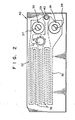
- heating element 30 is shown with fusible signal means or element 40 which is made during etching of stainless steel resistor 32. Opening 39 provides exposure of element 40. Terminal 42 exposed by opening 41 affords quality control checking of the resistor. Checking between shorted terminals 37 and 38 and terminal 42 will form two parallel paths of equal resistance.
- the fusible signal means can be a strip or wire made from a fusible elemental metal, metal alloy or other conductive material.
- fusible as used herein means that the strip or signal means becomes upon heating severed or separated by melting, vaporizing or oxidizing. Although the term “melt” will be used subsequently to exemplify how the fusible signal means becomes severed, it is to be understood that destruction by vaporization or oxidation equally applies.
- the strip or wire is made from a fusible elemental metal or metal alloy. Suitable materials include steel, stainless steel, nichrome, copper, aluminum, zinc, tin, lead and alloys of any of these materials.
- the fusible signal means is made from aluminum or stainless steel since these materials are commonly used in the art to make fusible links.
- the strip or wire can be made by appropriately dimensioning the width, thickness and length of the strip or diameter and length of the wire so that,within the desired circuit and within a repeatable heat-transfer environment, it will heat up rapidly to the melting point of the material used.
- the fusible signal means can also be made from a low melting point alloy, such as a eutectic alloy, which is not melted solely by the action of the current through it but rather by its close proximity to the heating element. In this embodiment, the melting point of the alloy must be below the temperature generated by the heating element.
- the resistance heating element has a resistor such as etched stainless steel foil and the fusible signal strip is made from stainless steel and is produced during etching of the resistor.
- the resistance heating element consists essentially of, as an outer layer, a folded sheet of metal having a thermal conductivity of at least about 173 watts/m°K at a 0.10 mm thickness and a tensile yield strength of at least about 34 x 10 4 kPa at a 0.10 mm thickness, the resistor disposed inside the fold of said folded sheet of metal; and a layer of dielectric adhesive, stable to about 260°C, between inner surfaces of said folded sheet of metal and surfaces of said resistor, thereby bonding the resulting structure together.
- the fusible signal means can be welded or mechanically crimped onto the desired location, can be pressure bonded to a roughened surface of the contact pads of the heating element, or can be connected by other methods known in the art.
- the fuse heat-transfer environment should be maintained constant.
- the improved heating element of the invention is used in the sterile connection apparatus described in U.S. Patent 4,369,779.
- the apparatus is equipped with a microprocessor capable of detecting the electrical signal generated by the fusible signal means.
- the improved resistance heating element of the invention when used in the sterile connection device as described in U.S. Patent 4,369,779 provides an electrical signal to indicate whether or not the heating element is being used for the first time.
- the fusible signal means then melts instantly permitting heating of the heating element to proceed. If multiple use of a heating element is being attempted, the microprocessor of the sterile connection device would not receive the electrical signal of the fusible signal means and would then reject the blade by refusing to continue through its heating and splicing cycle. An audible signal could be generated to tell the patient that the sterile connection operation has not been commenced.
- the presence of the fusible signal means can be determined by applying a low voltage to the heating element and then measuring the resistance. For instance, if the fusible signal means having a resistance of 2 ohms (R 1 ) was used in parallel with a 10 ohm (R 2 ) heating element resistor, the equivalent resistance, R , of the circuit would be Hence, R eq is 1.67 ohms which is slightly less than the fusible signal means resistance. If the fusible signal means had been absent, the resistance would have been that of the heating element resistor, i.e., 10 ohms. This differential of 83% is easily detected. Even if the fuse resistance equalled the blade resistance, the differential would be 50% which is still easily detected.
- Another and preferred method to detect the presence of the fusible signal means is to monitor the time it takes to reach the melt-voltage of the fusible signal means. A percent increase in time of about 200% between the absence and presence of the signal means can be obtained in the melt-voltage method.
- a third method for detecting the presence of the fusible signal means is to monitor the slope of the voltage/time curve for an inflection point where the signal means melts.
- a heating element was constructed with an outer layer made of rolled, annealed copper with a thickness of 0.11 mm, an etched stainless steel resistor with a thickness of about 0.025 mm, a layer of acrylic adhesive 0.025 mm in thickness.
- a stainless steel wire having a diameter of 0.04 mm (1.6 mil),.a length of 1.3 cm (0.5 inch) and a resistance of about 3 ohms was connected in parallel between the terminals of the resistor.
- the particular sterile connection apparatus used employs a 1.35 amp current for heating. When this current was applied to the heating element, the voltage/time relationship shown in Fig. 3 resulted. As can be seen from Fig.
Landscapes
- Engineering & Computer Science (AREA)
- Mechanical Engineering (AREA)
- Thermal Sciences (AREA)
- Physics & Mathematics (AREA)
- Health & Medical Sciences (AREA)
- Heart & Thoracic Surgery (AREA)
- Hematology (AREA)
- Biomedical Technology (AREA)
- Anesthesiology (AREA)
- Life Sciences & Earth Sciences (AREA)
- Animal Behavior & Ethology (AREA)
- General Health & Medical Sciences (AREA)
- Public Health (AREA)
- Veterinary Medicine (AREA)
- Pulmonology (AREA)
- Toxicology (AREA)
- Lining Or Joining Of Plastics Or The Like (AREA)
Abstract
There is disclosed an improved resistance heating element for welding thermoplastic tubes together, particular- ly for sterile welding. The improvement permits the indication of first use of the heating slement and comprises a fusible signal means to indicate first use of the heating element. The signal means provides an electrical signal which is eliminated prior to first use by melting of the signal means thereby enabling first use to be commenced, If the electrical signal is not generated, e.g., the heating element has been used once, the sterile connection apparatus in which the heating element is used is programmed to reject the heating element, thereby eliminating risks resulting from reusing the heating element.
Description
- This invention relates to a printed circuit heating element. More specifically, the present invention relates to a printed circuit heating element suitable for heating and welding two thermoplastic tubes together.
- At the present time there are a number of medical and scientific procedures which require the sterile transfer of fluids from one container to another. An example of the need for sterile docking is in continuous ambulatory peritoneal dialysis (CAPD). The CAPD patient has a tube connected to his or her peritoneal cavity via an implanted catheter. A tube from a bag of fresh dialysis solution is connected to the patient's tube. The fresh dialysis solution is drained from the bag into the patient's peritoneal. cavity where it remains for about 3-4 hrs. After this treatment period, the spent dialysate is drained back into the empty bag which is then disconnected from the patient's tube. A bag of fresh dialysis solution is then connected to the patient's tube and the procedure repeated. A similar need for sterile connection exists for blood bags.
- U.S. Patent 4,369,779*, issued to Spencer on January 25, 1983, discloses an apparatus and process for forming a sterile connection. The apparatus comprises a cutting means, means adapted to heat said cutting means, a pair of mounting blocks adapted to receive and hold two tubes to be joined, means to provide movement between said blocks and said cutting means to a position such that the cutting means is between said blocks and traversing where the blocks are adapted to receive tubes, means adapted to realign said blocks to a position where two different tube ends are aligned with and facing each other, and means to separate said blocks and said cutting means while urging said blocks together. The patent discloses that the cutting means can take many forms but preferably is a laminate strip constructed of an etched stainless steel ribbon having on each side an acrylic adhesive layer, an aromatic polyimide layer, an acrylic adhesive layer and a copper ribbon.
- Resistance heating elements for use in the aforesaid sterile connection apparatus can be reused if properly cleaned and if they are still structurally intact. However, improper cleaning may result in a joint of low strength and in contamination of the insides of the tubes which are welded together. Moreover, the number of times a heating element can be reused depends upon the particular element. Furthermore, the determination of whether a heating element has been properly cleaned or is structurally intact cannot be easily done by the ordinary user. Uncertainties such as these, subject the patient who is using the device to unnecessary risks of infection. A means by which these risks may be minimized, eliminated or avoided would prove advantageous.
- Fuses which melt to deactivate or bypass a circuit are well known. U.S. Patent 411,380 issued to Heller and U.S. Patent 1,803,486 issued to Rau are typical of patents disclosing fusible elements to bypass an incandescent electric lamp. U.S. Patent 2,874,248, issued to Tondat et al. on February 17, 1959, discloses a multiple fuse assembly having a movable bridging contactor to engage one fuse at a time. The patent discloses that the assembly may be produced by printed circuit technology or by spraying a paint containing powdered metal through a suitable mask to produce the desired outline on an insulating board, and then drying and baking the resulting coating.
- U.S. Patent 3,249,800, issued to Huber on May 3, 1966, discloses a fast acting switch wherein a small metal wire is exploded electrically and rapidly to pulse a circuit by electrically disintegrating the wire explosively to form a rapidly expanding, current carrying, low impedence conducting medium in the gap between two closely spaced conductors so as to actuate and conduct the flow of current between the conductors.
- U.S. Patent 4,169,254, issued to Kennedy et al. on September 25, 1979, discloses a manually actuable electric switch having a fusible element which melts on subjection to a predetermined temperature to discontinue the flow of electric current through the switch. A manually operable plunger normally used to open and close the switch is mechanically connected to the stem of the switch through the fusible element. Melting of the element severs the mechanical connection between the plunger and switch thereby deactivating the switch.
- The present invention provides an improvement in a resistance heating element for welding thermoplastic tubes together. The improvement comprises a fusible signal means to indicate first use of the element, said signal means being connected in parallel to the resistor of said heating element and providing an electrical signal which is eliminated during first use of said heating element.
-
- Fig. 1 is a plan view of a heating element having a fusible signal means in accordance with the present invention.
- Fig. 2 is a plan view of a heating element having a fusible signal means in accordance with another embodiment of the present invention.
- Fig. 3 is a graph depicting a voltage-time relationship for heating element of the invention.
- Referring to Fig. 1,
heating element 10 is shown withresistor 12 which is made from etched stainless steel foil for this embodiment.Resistor 12 is disposed in the fold of a folded sheet 11 of metal which in the figure is copper and serves as the outer layer of the heating element.Openings contacts resistor 12.Opening 19 is also provided on one side of the folded sheet 11 to expose fusible signal means 20 which for the embodiment disclosed in the figure is a stainless steel wire. The fusible signal means can be connected in parallel to all or at least part of the resistor. - Referring now to Fig. 2,
heating element 30 is shown with fusible signal means orelement 40 which is made during etching ofstainless steel resistor 32.Opening 39 provides exposure ofelement 40.Terminal 42 exposed by opening 41 affords quality control checking of the resistor. Checking between shortedterminals terminal 42 will form two parallel paths of equal resistance. - The fusible signal means can be a strip or wire made from a fusible elemental metal, metal alloy or other conductive material. The term "fusible" as used herein means that the strip or signal means becomes upon heating severed or separated by melting, vaporizing or oxidizing. Although the term "melt" will be used subsequently to exemplify how the fusible signal means becomes severed, it is to be understood that destruction by vaporization or oxidation equally applies. Preferably, the strip or wire is made from a fusible elemental metal or metal alloy. Suitable materials include steel, stainless steel, nichrome, copper, aluminum, zinc, tin, lead and alloys of any of these materials. Preferably, the fusible signal means is made from aluminum or stainless steel since these materials are commonly used in the art to make fusible links. The strip or wire can be made by appropriately dimensioning the width, thickness and length of the strip or diameter and length of the wire so that,within the desired circuit and within a repeatable heat-transfer environment, it will heat up rapidly to the melting point of the material used. The fusible signal means can also be made from a low melting point alloy, such as a eutectic alloy, which is not melted solely by the action of the current through it but rather by its close proximity to the heating element. In this embodiment, the melting point of the alloy must be below the temperature generated by the heating element.
- In a preferred embodiment of the invention the resistance heating element has a resistor such as etched stainless steel foil and the fusible signal strip is made from stainless steel and is produced during etching of the resistor. Preferably, in this embodiment of the invention, the resistance heating element consists essentially of, as an outer layer, a folded sheet of metal having a thermal conductivity of at least about 173 watts/m°K at a 0.10 mm thickness and a tensile yield strength of at least about 34 x 104 kPa at a 0.10 mm thickness, the resistor disposed inside the fold of said folded sheet of metal; and a layer of dielectric adhesive, stable to about 260°C, between inner surfaces of said folded sheet of metal and surfaces of said resistor, thereby bonding the resulting structure together.
- The fusible signal means can be welded or mechanically crimped onto the desired location, can be pressure bonded to a roughened surface of the contact pads of the heating element, or can be connected by other methods known in the art. For a repeatable operation where the critical measurement is a small change in heat-up time, the fuse heat-transfer environment should be maintained constant.
- The improved heating element of the invention is used in the sterile connection apparatus described in U.S. Patent 4,369,779. Preferably, the apparatus is equipped with a microprocessor capable of detecting the electrical signal generated by the fusible signal means.
- The improved resistance heating element of the invention when used in the sterile connection device as described in U.S. Patent 4,369,779 provides an electrical signal to indicate whether or not the heating element is being used for the first time. The fusible signal means then melts instantly permitting heating of the heating element to proceed. If multiple use of a heating element is being attempted, the microprocessor of the sterile connection device would not receive the electrical signal of the fusible signal means and would then reject the blade by refusing to continue through its heating and splicing cycle. An audible signal could be generated to tell the patient that the sterile connection operation has not been commenced.
- The presence of the fusible signal means can be determined by applying a low voltage to the heating element and then measuring the resistance. For instance, if the fusible signal means having a resistance of 2 ohms (R1) was used in parallel with a 10 ohm (R2) heating element resistor, the equivalent resistance, R , of the circuit would be

- Another and preferred method to detect the presence of the fusible signal means is to monitor the time it takes to reach the melt-voltage of the fusible signal means. A percent increase in time of about 200% between the absence and presence of the signal means can be obtained in the melt-voltage method. A third method for detecting the presence of the fusible signal means is to monitor the slope of the voltage/time curve for an inflection point where the signal means melts.
- A heating element was constructed with an outer layer made of rolled, annealed copper with a thickness of 0.11 mm, an etched stainless steel resistor with a thickness of about 0.025 mm, a layer of acrylic adhesive 0.025 mm in thickness. A stainless steel wire having a diameter of 0.04 mm (1.6 mil),.a length of 1.3 cm (0.5 inch) and a resistance of about 3 ohms was connected in parallel between the terminals of the resistor. The particular sterile connection apparatus used employs a 1.35 amp current for heating. When this current was applied to the heating element, the voltage/time relationship shown in Fig. 3 resulted. As can be seen from Fig. 3, the time to reach a preselected voltage, the fuse-melt voltage, was considerably different with as compared to without a fuse. To reach a value of 8.5 volts it took 53 milliseconds with the steel wire as a fuse and only 17 milliseconds without it. This 36 millisecond difference can be readily detected with the microprocessor of the apparatus. If the heating elements are carefully quality controlled to assure that each will reach a desired voltage within a time period that retains significance for this difference between the presence and absence of the fuse, then the apparatus can be programmed to indicate when a heating element has reached the desired voltage too rapidly, thereby determining whether the fuse was absent and thus an attempted nonfirst use.
Claims (9)
1. In a resistance heating element for welding thermoplastic tubes together, the improvement comprising, in combination with said heating element's resistor, a fusible signal means to indicate first use of the,element, said signal means being connected in parallel to the resistor of said heating element and providing an electrical signal which is eliminated during first use of said heating element.
2. A resistance heating element according to Claim 1 wherein the fusible signal means is a strip or wire of fusible metal or alloy.
3. A resistance heating element according to Claim 2 wherein the fusible signal means is stainless steel alloy.
4. A resistance heating element according to Claim 3 wherein the heating element has an etched stainless steel foil resistor and the fusible signal strip of stainless steel is made during etching of the resistor.
5. In a heating element for welding first and second thermoplastic tubes together transversely of the axis of each tube consisting essentially of, as an outer layer, a folded sheet of metal having a thermal conductivity of at least about 173 watts/m°K at a 0.10 mm thickness and a tensile yield strength of at least about 34 x 10 4 kPa at 0.10 mm thickness, an etched stainless steel foil resistor disposed inside the fold of said folded sheet of metal; and a layer of dielectric adhesive, stable to about 260°C, between inner surfaces of said folded sheet of metal and surfaces of said resistor, thereby bonding the resulting structure together, the improvement comprising a fusible signal strip of stainless steel connected in parallel to the resistor and providing an electrical signal which is eliminated during first use of the heating element, said fusible signal strip being made during etching of the resistor.
6. In an apparatus for forming a sterile connection between two thermoplastic tubes which comprises a cutting means, a pair of mounting blocks adapted to receive and hold the two tubes, means to provide movement between said blocks and said cutting means to a position such that the cutting means is between said blocks and traversing where the blocks are adapted to receive tubes, means adapted to realign said blocks to a position where two different tube ends are aligned with and facing each other, means to separate said blocks and said cutting means while urging saidkblocks together; and a microprocessor to control means to provide movement between blocks and cutting means, realignment means, separating means and urging of said blocks together; the improvement comprising that the cutting means is a resistance heating element having a fusible signal means to indicate first use of the element, said signal means being connected in parallel to the resistor of said heating element and providing an electrical signal which is detectable by said microprocessor and which is eliminated during firt use of the heating element.
7. An apparatus according to Claim 6, wherein the fusible signal means is stainless steel alloy.
8. An apparatus according to Claim 7, wherein the fusible signal means is a stainless steel wire connected between contacts of said heating element, said wire having a diameter of about 0.038 mm and a length of at least about 2 mm.
9. An apparatus according to Claim 7 or 8, wherein the heating element has an etched stainless steel foil resistor and the fusible signal strip of stainless steel is made during etching of the resistor.
Applications Claiming Priority (2)
| Application Number | Priority Date | Filing Date | Title |
|---|---|---|---|
| US06/511,017 US4647756A (en) | 1983-07-05 | 1983-07-05 | Electrical resistance heating element with signal means to indicate first use |
| US511017 | 1983-07-05 |
Publications (1)
| Publication Number | Publication Date |
|---|---|
| EP0139350A1 true EP0139350A1 (en) | 1985-05-02 |
Family
ID=24033118
Family Applications (1)
| Application Number | Title | Priority Date | Filing Date |
|---|---|---|---|
| EP19840304569 Withdrawn EP0139350A1 (en) | 1983-07-05 | 1984-07-04 | First use indicator for a sterile docking cutting means |
Country Status (2)
| Country | Link |
|---|---|
| US (1) | US4647756A (en) |
| EP (1) | EP0139350A1 (en) |
Cited By (4)
| Publication number | Priority date | Publication date | Assignee | Title |
|---|---|---|---|---|
| EP0812665A4 (en) * | 1995-03-02 | 1998-07-01 | Terumo Corp | Hot cutting blade |
| US10919235B2 (en) | 2017-06-07 | 2021-02-16 | Fenwal, Inc. | Apparatus and method for mechanically opening a connection site |
| WO2024069835A1 (en) * | 2022-09-29 | 2024-04-04 | Terumo Kabushiki Kaisha | Fusion bonding wafer, tube fusion bonding device, and tube fusion bonding method |
| EP3795339B1 (en) * | 2019-09-17 | 2025-03-05 | Urban GmbH & Co. Maschinenbau KG | Heating element for heating plastics profiles and method for removing material outside the welding zone |
Families Citing this family (27)
| Publication number | Priority date | Publication date | Assignee | Title |
|---|---|---|---|---|
| JP3220229B2 (en) * | 1992-05-26 | 2001-10-22 | テルモ株式会社 | Heating element for tube connection device and method of manufacturing the same |
| JPH0780041A (en) * | 1993-09-20 | 1995-03-28 | Terumo Corp | Cell preserving bag system |
| US7090658B2 (en) * | 1997-03-03 | 2006-08-15 | Medical Solutions, Inc. | Temperature sensing device for selectively measuring temperature at desired locations along an intravenous fluid line |
| AU6683498A (en) | 1997-03-03 | 1998-09-22 | Medical Solutions, Inc. | Method and apparatus for pressure infusion and temperature control of infused liquids |
| US7041941B2 (en) * | 1997-04-07 | 2006-05-09 | Patented Medical Solutions, Llc | Medical item thermal treatment systems and method of monitoring medical items for compliance with prescribed requirements |
| US7276675B2 (en) * | 1997-04-07 | 2007-10-02 | Patented Medical Solutions, Llc | Medical item thermal treatment systems and method of monitoring medical items for compliance with prescribed requirements |
| US6660974B2 (en) * | 1997-04-07 | 2003-12-09 | Medical Solutions, Inc. | Warming system and method for heating various items utilized in surgical procedures |
| US6467953B1 (en) * | 1999-03-30 | 2002-10-22 | Medical Solutions, Inc. | Method and apparatus for monitoring temperature of intravenously delivered fluids and other medical items |
| MXPA01012074A (en) * | 1999-06-09 | 2003-06-30 | Kazuko Sakamoto | Heater wire for device such as impulse heat sealer. |
| WO2001089008A1 (en) * | 2000-05-16 | 2001-11-22 | Flexcon Company, Inc. | First use indicator label |
| US7031602B2 (en) * | 2001-03-12 | 2006-04-18 | Patented Medical Solutions, Llc | Method and apparatus for controlling temperature of infused liquids |
| US7238171B2 (en) * | 2001-03-12 | 2007-07-03 | Medical Solutions, Inc. | Method and apparatus for controlling pressurized infusion and temperature of infused liquids |
| US7176030B2 (en) * | 2002-06-17 | 2007-02-13 | O.R. Solutions, Inc. | Method and apparatus for ensuring sterility of disposable medical items used with medical equipment |
| US8226605B2 (en) | 2001-12-17 | 2012-07-24 | Medical Solutions, Inc. | Method and apparatus for heating solutions within intravenous lines to desired temperatures during infusion |
| JP4101511B2 (en) * | 2001-12-27 | 2008-06-18 | 株式会社半導体エネルギー研究所 | Light emitting device and manufacturing method thereof |
| JP4046655B2 (en) * | 2003-07-04 | 2008-02-13 | テルモ株式会社 | Tube joining device |
| US7338130B2 (en) * | 2004-12-06 | 2008-03-04 | Honda Motor Co., Ltd. | Locking headrest assembly |
| US7740611B2 (en) * | 2005-10-27 | 2010-06-22 | Patented Medical Solutions, Llc | Method and apparatus to indicate prior use of a medical item |
| US8487738B2 (en) * | 2006-03-20 | 2013-07-16 | Medical Solutions, Inc. | Method and apparatus for securely storing medical items within a thermal treatment system |
| US20080234625A1 (en) * | 2006-10-16 | 2008-09-25 | Bruno Dacquay | Fuse Assembly For Single Use Medical Device |
| US8226293B2 (en) | 2007-02-22 | 2012-07-24 | Medical Solutions, Inc. | Method and apparatus for measurement and control of temperature for infused liquids |
| US20090250440A1 (en) * | 2008-04-04 | 2009-10-08 | Yap Tze-Yee Ryan | Out-of-phase electrical welder and process |
| WO2012006722A1 (en) * | 2010-07-13 | 2012-01-19 | Tyler Johnson | Portable rechargeable battery powered flameless cigar lighter |
| US9211381B2 (en) | 2012-01-20 | 2015-12-15 | Medical Solutions, Inc. | Method and apparatus for controlling temperature of medical liquids |
| WO2014126964A1 (en) | 2013-02-15 | 2014-08-21 | Medical Solutions, Inc. | Plural medical item warming system and method for warming a plurality of medical items to desired temperatures |
| FR3097464B1 (en) * | 2019-06-19 | 2021-07-02 | Mga Tech | Heated blade with wear indicator |
| EP4035723A1 (en) | 2021-01-25 | 2022-08-03 | Fenwal, Inc. | Sterile connection of tubing |
Citations (6)
| Publication number | Priority date | Publication date | Assignee | Title |
|---|---|---|---|---|
| US4174996A (en) * | 1975-10-07 | 1979-11-20 | John Hunter | Pipe jointing |
| US4263084A (en) * | 1979-06-22 | 1981-04-21 | Impala Plastics (Pty) Limited | Thermoplastic welding |
| US4369779A (en) * | 1981-02-23 | 1983-01-25 | E. I. Du Pont De Nemours And Company | Sterile docking process, apparatus and system |
| EP0103977A1 (en) * | 1982-08-16 | 1984-03-28 | E.I. Du Pont De Nemours And Company | Improved sterile docking cutting means |
| EP0105587A1 (en) * | 1982-08-16 | 1984-04-18 | E.I. Du Pont De Nemours And Company | Automatic splicing device |
| EP0044204B1 (en) * | 1980-07-11 | 1985-04-10 | E.I. Du Pont De Nemours And Company | Sterile docking process, apparatus and system |
Family Cites Families (20)
| Publication number | Priority date | Publication date | Assignee | Title |
|---|---|---|---|---|
| US411380A (en) * | 1889-09-17 | Out-out | ||
| US426024A (en) * | 1890-04-22 | John von dee kammer | ||
| US1203125A (en) * | 1914-10-03 | 1916-10-31 | Cons Car Heating Co | Protective device for electric heaters. |
| US1549984A (en) * | 1924-11-25 | 1925-08-18 | Cons Car Heating Co | Trainman's safety circuit |
| US1803486A (en) * | 1927-06-22 | 1931-05-05 | Westinghouse Lamp Co | Cut-out for incandescent electric lamps |
| US2159649A (en) * | 1938-01-19 | 1939-05-23 | Mackay Radio & Telegraph Compa | Circuit arrangement for reducing transients |
| US2874248A (en) * | 1956-09-11 | 1959-02-17 | Gen Dynamics Corp | Multiple fuse |
| US3182153A (en) * | 1962-08-15 | 1965-05-04 | Mc Graw Edison Co | Electrical equipment provided with a visual indicator |
| US3249800A (en) * | 1963-08-02 | 1966-05-03 | Henry J Huber | Fast acting switch utilizing a vaporizable wire |
| US3423574A (en) * | 1965-10-14 | 1969-01-21 | Sanders Associates Inc | Electrical resistance heating pad |
| US3423567A (en) * | 1966-12-08 | 1969-01-21 | Fieldcrest Mills Inc | Electrically heated bedcovering |
| US3693048A (en) * | 1970-10-19 | 1972-09-19 | Gen Motors Corp | Fail open semiconductors |
| US3924099A (en) * | 1974-11-04 | 1975-12-02 | William W Housel | Forced circulation electric heater |
| US4044224A (en) * | 1976-03-01 | 1977-08-23 | General Electric Company | Protective circuit for dishwasher heating element |
| US4169254A (en) * | 1977-12-27 | 1979-09-25 | Corken International Corporation | Thermally activated emergency electric switch |
| US4342977A (en) * | 1978-12-18 | 1982-08-03 | Mcgalliard James D | Printed circuit fuse assembly |
| NO146836C (en) * | 1980-10-10 | 1982-12-22 | Standard Tel Kabelfab As | ELECTRICAL HEATING ELEMENT. |
| US4406280A (en) * | 1981-10-16 | 1983-09-27 | Upsher Michael S | Laryngoscope including a disposable blade and its method of use |
| EP0093821B1 (en) * | 1982-05-12 | 1987-05-06 | Geberit AG | Welding socket |
| US4479105A (en) * | 1983-03-08 | 1984-10-23 | G & W Electric Company | Pyrotechnic current interrupter |
-
1983
- 1983-07-05 US US06/511,017 patent/US4647756A/en not_active Expired - Lifetime
-
1984
- 1984-07-04 EP EP19840304569 patent/EP0139350A1/en not_active Withdrawn
Patent Citations (6)
| Publication number | Priority date | Publication date | Assignee | Title |
|---|---|---|---|---|
| US4174996A (en) * | 1975-10-07 | 1979-11-20 | John Hunter | Pipe jointing |
| US4263084A (en) * | 1979-06-22 | 1981-04-21 | Impala Plastics (Pty) Limited | Thermoplastic welding |
| EP0044204B1 (en) * | 1980-07-11 | 1985-04-10 | E.I. Du Pont De Nemours And Company | Sterile docking process, apparatus and system |
| US4369779A (en) * | 1981-02-23 | 1983-01-25 | E. I. Du Pont De Nemours And Company | Sterile docking process, apparatus and system |
| EP0103977A1 (en) * | 1982-08-16 | 1984-03-28 | E.I. Du Pont De Nemours And Company | Improved sterile docking cutting means |
| EP0105587A1 (en) * | 1982-08-16 | 1984-04-18 | E.I. Du Pont De Nemours And Company | Automatic splicing device |
Cited By (6)
| Publication number | Priority date | Publication date | Assignee | Title |
|---|---|---|---|---|
| EP0812665A4 (en) * | 1995-03-02 | 1998-07-01 | Terumo Corp | Hot cutting blade |
| US10919235B2 (en) | 2017-06-07 | 2021-02-16 | Fenwal, Inc. | Apparatus and method for mechanically opening a connection site |
| US11325321B2 (en) | 2017-06-07 | 2022-05-10 | Fenwal, Inc. | Apparatus and method for mechanically opening a connection site |
| EP3795339B1 (en) * | 2019-09-17 | 2025-03-05 | Urban GmbH & Co. Maschinenbau KG | Heating element for heating plastics profiles and method for removing material outside the welding zone |
| WO2024069835A1 (en) * | 2022-09-29 | 2024-04-04 | Terumo Kabushiki Kaisha | Fusion bonding wafer, tube fusion bonding device, and tube fusion bonding method |
| JP2025523741A (en) * | 2022-09-29 | 2025-07-25 | テルモ株式会社 | Welded wafer, tube welding device, and tube welding method |
Also Published As
| Publication number | Publication date |
|---|---|
| US4647756A (en) | 1987-03-03 |
Similar Documents
| Publication | Publication Date | Title |
|---|---|---|
| US4647756A (en) | Electrical resistance heating element with signal means to indicate first use | |
| EP0571978B1 (en) | Heater element for a tube connecting device | |
| EP0103977B1 (en) | Improved sterile docking cutting means | |
| US5345070A (en) | Radio frequency tubing sealer | |
| US5182440A (en) | Process and connection component using an electrical resistor for the welding of plastic elements | |
| US5408577A (en) | Method and heater apparatus with protective fuse for medical applications | |
| US4317367A (en) | Fever thermometer, or the like sensor | |
| EP0964419B1 (en) | Thin type thermal fuse and manufacturing method thereof | |
| EP0517306B1 (en) | Heat actuated fuse apparatus with solder link | |
| EP0371630B1 (en) | Self regulating temperature heater carrier strip | |
| EP0371646B1 (en) | Self regulating temperature heater with thermally conductive extensions | |
| US3155809A (en) | Means and techniques for making electrical connections | |
| JPS61281490A (en) | Electric circuit and monitoring thereof | |
| JPH08308935A (en) | High frequency power supply for heating | |
| US7361830B2 (en) | Polymer encapsulated micro-thermocouple | |
| CA1051096A (en) | Method of joining aluminum to aluminum and a machine for such method | |
| US5932132A (en) | Sterile connector apparatus and method | |
| EP0371644B1 (en) | Surface mount technology breakaway self regulating temperature heater | |
| JPS5852534A (en) | Temperature detecting apparatus | |
| EP0064599B1 (en) | Sensors designed for the measurement of temperature as well as methods of adjusting them | |
| JP4421444B2 (en) | High frequency power supply for medical devices | |
| JP4865968B2 (en) | Contact heating element | |
| US20020144778A1 (en) | Apparatus for high-speed heating and cooling of a polymer | |
| JP2555721Y2 (en) | Electric fumigator | |
| EP0853546B1 (en) | Sealed boot on an electrical cable |
Legal Events
| Date | Code | Title | Description |
|---|---|---|---|
| PUAI | Public reference made under article 153(3) epc to a published international application that has entered the european phase |
Free format text: ORIGINAL CODE: 0009012 |
|
| AK | Designated contracting states |
Designated state(s): BE DE FR GB IT NL SE |
|
| 17P | Request for examination filed |
Effective date: 19851028 |
|
| 17Q | First examination report despatched |
Effective date: 19860912 |
|
| STAA | Information on the status of an ep patent application or granted ep patent |
Free format text: STATUS: THE APPLICATION IS DEEMED TO BE WITHDRAWN |
|
| 18D | Application deemed to be withdrawn |
Effective date: 19870123 |
|
| RIN1 | Information on inventor provided before grant (corrected) |
Inventor name: WILLIS, FRANK MARSDEN |