EP3793459B1 - A device for denuding a body lumen - Google Patents
A device for denuding a body lumen Download PDFInfo
- Publication number
- EP3793459B1 EP3793459B1 EP19730654.1A EP19730654A EP3793459B1 EP 3793459 B1 EP3793459 B1 EP 3793459B1 EP 19730654 A EP19730654 A EP 19730654A EP 3793459 B1 EP3793459 B1 EP 3793459B1
- Authority
- EP
- European Patent Office
- Prior art keywords
- vein
- coil
- helical coil
- vessel
- lumen
- Prior art date
- Legal status (The legal status is an assumption and is not a legal conclusion. Google has not performed a legal analysis and makes no representation as to the accuracy of the status listed.)
- Active
Links
Images


Classifications
-
- A—HUMAN NECESSITIES
- A61—MEDICAL OR VETERINARY SCIENCE; HYGIENE
- A61B—DIAGNOSIS; SURGERY; IDENTIFICATION
- A61B17/00—Surgical instruments, devices or methods
- A61B17/00008—Vein tendon strippers
-
- A—HUMAN NECESSITIES
- A61—MEDICAL OR VETERINARY SCIENCE; HYGIENE
- A61B—DIAGNOSIS; SURGERY; IDENTIFICATION
- A61B17/00—Surgical instruments, devices or methods
- A61B17/12—Surgical instruments, devices or methods for ligaturing or otherwise compressing tubular parts of the body, e.g. blood vessels or umbilical cord
- A61B17/12022—Occluding by internal devices, e.g. balloons or releasable wires
- A61B17/12131—Occluding by internal devices, e.g. balloons or releasable wires characterised by the type of occluding device
-
- A—HUMAN NECESSITIES
- A61—MEDICAL OR VETERINARY SCIENCE; HYGIENE
- A61B—DIAGNOSIS; SURGERY; IDENTIFICATION
- A61B17/00—Surgical instruments, devices or methods
- A61B17/32—Surgical cutting instruments
- A61B17/3205—Excision instruments
-
- A—HUMAN NECESSITIES
- A61—MEDICAL OR VETERINARY SCIENCE; HYGIENE
- A61B—DIAGNOSIS; SURGERY; IDENTIFICATION
- A61B17/00—Surgical instruments, devices or methods
- A61B17/32—Surgical cutting instruments
- A61B17/3205—Excision instruments
- A61B17/3207—Atherectomy devices working by cutting or abrading; Similar devices specially adapted for non-vascular obstructions
- A61B17/320758—Atherectomy devices working by cutting or abrading; Similar devices specially adapted for non-vascular obstructions with a rotating cutting instrument, e.g. motor driven
-
- A—HUMAN NECESSITIES
- A61—MEDICAL OR VETERINARY SCIENCE; HYGIENE
- A61B—DIAGNOSIS; SURGERY; IDENTIFICATION
- A61B18/00—Surgical instruments, devices or methods for transferring non-mechanical forms of energy to or from the body
- A61B18/04—Surgical instruments, devices or methods for transferring non-mechanical forms of energy to or from the body by heating
- A61B18/12—Surgical instruments, devices or methods for transferring non-mechanical forms of energy to or from the body by heating by passing a current through the tissue to be heated, e.g. high-frequency current
- A61B18/14—Probes or electrodes therefor
- A61B18/1492—Probes or electrodes therefor having a flexible, catheter-like structure, e.g. for heart ablation
-
- A—HUMAN NECESSITIES
- A61—MEDICAL OR VETERINARY SCIENCE; HYGIENE
- A61B—DIAGNOSIS; SURGERY; IDENTIFICATION
- A61B17/00—Surgical instruments, devices or methods
- A61B17/12—Surgical instruments, devices or methods for ligaturing or otherwise compressing tubular parts of the body, e.g. blood vessels or umbilical cord
- A61B17/12022—Occluding by internal devices, e.g. balloons or releasable wires
- A61B17/12027—Type of occlusion
- A61B17/1204—Type of occlusion temporary occlusion
-
- A—HUMAN NECESSITIES
- A61—MEDICAL OR VETERINARY SCIENCE; HYGIENE
- A61B—DIAGNOSIS; SURGERY; IDENTIFICATION
- A61B17/00—Surgical instruments, devices or methods
- A61B17/12—Surgical instruments, devices or methods for ligaturing or otherwise compressing tubular parts of the body, e.g. blood vessels or umbilical cord
- A61B17/12022—Occluding by internal devices, e.g. balloons or releasable wires
- A61B17/12099—Occluding by internal devices, e.g. balloons or releasable wires characterised by the location of the occluder
- A61B17/12109—Occluding by internal devices, e.g. balloons or releasable wires characterised by the location of the occluder in a blood vessel
-
- A—HUMAN NECESSITIES
- A61—MEDICAL OR VETERINARY SCIENCE; HYGIENE
- A61B—DIAGNOSIS; SURGERY; IDENTIFICATION
- A61B17/00—Surgical instruments, devices or methods
- A61B17/12—Surgical instruments, devices or methods for ligaturing or otherwise compressing tubular parts of the body, e.g. blood vessels or umbilical cord
- A61B17/12022—Occluding by internal devices, e.g. balloons or releasable wires
- A61B17/12131—Occluding by internal devices, e.g. balloons or releasable wires characterised by the type of occluding device
- A61B17/12136—Balloons
-
- A—HUMAN NECESSITIES
- A61—MEDICAL OR VETERINARY SCIENCE; HYGIENE
- A61B—DIAGNOSIS; SURGERY; IDENTIFICATION
- A61B17/00—Surgical instruments, devices or methods
- A61B17/00008—Vein tendon strippers
- A61B2017/00013—Cables with a stripper head
-
- A—HUMAN NECESSITIES
- A61—MEDICAL OR VETERINARY SCIENCE; HYGIENE
- A61B—DIAGNOSIS; SURGERY; IDENTIFICATION
- A61B17/00—Surgical instruments, devices or methods
- A61B17/0057—Implements for plugging an opening in the wall of a hollow or tubular organ, e.g. for sealing a vessel puncture or closing a cardiac septal defect
- A61B2017/00641—Implements for plugging an opening in the wall of a hollow or tubular organ, e.g. for sealing a vessel puncture or closing a cardiac septal defect for closing fistulae, e.g. anorectal fistulae
-
- A—HUMAN NECESSITIES
- A61—MEDICAL OR VETERINARY SCIENCE; HYGIENE
- A61B—DIAGNOSIS; SURGERY; IDENTIFICATION
- A61B17/00—Surgical instruments, devices or methods
- A61B2017/00743—Type of operation; Specification of treatment sites
- A61B2017/00778—Operations on blood vessels
-
- A—HUMAN NECESSITIES
- A61—MEDICAL OR VETERINARY SCIENCE; HYGIENE
- A61B—DIAGNOSIS; SURGERY; IDENTIFICATION
- A61B17/00—Surgical instruments, devices or methods
- A61B2017/00831—Material properties
- A61B2017/00867—Material properties shape memory effect
-
- A—HUMAN NECESSITIES
- A61—MEDICAL OR VETERINARY SCIENCE; HYGIENE
- A61B—DIAGNOSIS; SURGERY; IDENTIFICATION
- A61B17/00—Surgical instruments, devices or methods
- A61B17/22—Implements for squeezing-off ulcers or the like on inner organs of the body; Implements for scraping-out cavities of body organs, e.g. bones; for invasive removal or destruction of calculus using mechanical vibrations; for removing obstructions in blood vessels, not otherwise provided for
- A61B2017/22051—Implements for squeezing-off ulcers or the like on inner organs of the body; Implements for scraping-out cavities of body organs, e.g. bones; for invasive removal or destruction of calculus using mechanical vibrations; for removing obstructions in blood vessels, not otherwise provided for with an inflatable part, e.g. balloon, for positioning, blocking, or immobilisation
- A61B2017/22065—Functions of balloons
-
- A—HUMAN NECESSITIES
- A61—MEDICAL OR VETERINARY SCIENCE; HYGIENE
- A61B—DIAGNOSIS; SURGERY; IDENTIFICATION
- A61B17/00—Surgical instruments, devices or methods
- A61B17/32—Surgical cutting instruments
- A61B2017/320004—Surgical cutting instruments abrasive
-
- A—HUMAN NECESSITIES
- A61—MEDICAL OR VETERINARY SCIENCE; HYGIENE
- A61B—DIAGNOSIS; SURGERY; IDENTIFICATION
- A61B17/00—Surgical instruments, devices or methods
- A61B17/32—Surgical cutting instruments
- A61B2017/320004—Surgical cutting instruments abrasive
- A61B2017/320008—Scrapers
-
- A—HUMAN NECESSITIES
- A61—MEDICAL OR VETERINARY SCIENCE; HYGIENE
- A61B—DIAGNOSIS; SURGERY; IDENTIFICATION
- A61B17/00—Surgical instruments, devices or methods
- A61B17/32—Surgical cutting instruments
- A61B17/3205—Excision instruments
- A61B17/3207—Atherectomy devices working by cutting or abrading; Similar devices specially adapted for non-vascular obstructions
- A61B2017/320733—Atherectomy devices working by cutting or abrading; Similar devices specially adapted for non-vascular obstructions with a flexible cutting or scraping element, e.g. with a whip-like distal filament member
-
- A—HUMAN NECESSITIES
- A61—MEDICAL OR VETERINARY SCIENCE; HYGIENE
- A61B—DIAGNOSIS; SURGERY; IDENTIFICATION
- A61B17/00—Surgical instruments, devices or methods
- A61B17/32—Surgical cutting instruments
- A61B17/3205—Excision instruments
- A61B17/3207—Atherectomy devices working by cutting or abrading; Similar devices specially adapted for non-vascular obstructions
- A61B2017/320741—Atherectomy devices working by cutting or abrading; Similar devices specially adapted for non-vascular obstructions for stripping the intima or the internal plaque from a blood vessel, e.g. for endarterectomy
-
- A—HUMAN NECESSITIES
- A61—MEDICAL OR VETERINARY SCIENCE; HYGIENE
- A61B—DIAGNOSIS; SURGERY; IDENTIFICATION
- A61B18/00—Surgical instruments, devices or methods for transferring non-mechanical forms of energy to or from the body
- A61B2018/00315—Surgical instruments, devices or methods for transferring non-mechanical forms of energy to or from the body for treatment of particular body parts
- A61B2018/00345—Vascular system
- A61B2018/00404—Blood vessels other than those in or around the heart
-
- A—HUMAN NECESSITIES
- A61—MEDICAL OR VETERINARY SCIENCE; HYGIENE
- A61M—DEVICES FOR INTRODUCING MEDIA INTO, OR ONTO, THE BODY; DEVICES FOR TRANSDUCING BODY MEDIA OR FOR TAKING MEDIA FROM THE BODY; DEVICES FOR PRODUCING OR ENDING SLEEP OR STUPOR
- A61M25/00—Catheters; Hollow probes
- A61M25/0067—Catheters; Hollow probes characterised by the distal end, e.g. tips
- A61M25/0082—Catheter tip comprising a tool
Definitions
- Varicose veins are dilated, tortuous veins which are associated with structural vessel wall changes, incompetent venous valves, reflux and pooling of blood. They form part of the spectrum of chronic venous disease (CVD). Patients experience symptoms ranging from heaviness, aching pain and swelling to skin irritation, discolouration and ulceration in severe cases. The cause of varicose veins is unknown but genetic factors leading to weakness in vein wall components and valves are important in their development.
- Veins have thinner walls in contrast to the thicker more elastic walls of arteries. Veins are more compliant (flexible) allowing their lumen to range from a collapsed form in low pressure states to a distended form when increases in venous pressures occur.
- the saphenous vein wall thickness typically ranges from 200 to 700 micro metres ( ⁇ m).
- the wall comprises of three primary layers: the tunica intima, media and externa. However, unlike arteries the thickness and composition of the layers are different resulting in more compliant, less muscular vessels.
- the intimal layer comprises of a single layer of squamous cells known as the endothelium and some thin elastic fibres, collagen and smooth muscle cells.
- Blood clotting or thrombosis can occur in both the deep and superficial venous networks. Thrombus in superficial veins is usually self-contained due to low-flow throughput and rarely propagates to the deep venous network. It is not dangerous to the patient and does not require treatment unless there is associated inflammation known as thrombophlebitis.
- thrombophlebitis Thrombosis in the deep veins of the leg, known as deep vein thrombosis (DVT) is clinically relevant as it can cause venous outflow obstruction, raising venous pressure and leading to oedema in the leg.
- the thrombus can also travel (embolise) to the lung causing a potentially fatal condition known as pulmonary embolism (PE).
- PE pulmonary embolism
- Treatment options range from conservative compression hosiery to surgical procedures. In the USA approximately 600,000 to 700,000 procedures take place per year to treat varicose veins. There the treatment of varicose veins has transitioned from open surgery (involving stripping out of the entire GSV) to less invasive thermal endovenous catheter-based techniques (involving radiofrequency or laser energy). Some countries including Germany and the United Kingdom, still perform a large portion of open vein stripping procedures.
- thermal energy In general, catheter directed minimally invasive thermal based treatments are used to treat superficial venous reflux today.
- a significant limitation of using thermal energy is the need for multiple preparation injections of high volumes of local anaesthetic mixed with saline (tumescence) to insulate the vein and protect surrounding tissues from thermal injury. This is both time-consuming for the physician and painful for the patient due to the requirement of multiple needle stick injections to the leg.
- tumescence As space is required between the skin and the vein for injection of tumescence, it also limits treatment when veins are located close to important nerves (as is the case with treatment of veins below the knee), near the skin or close to ulcers in patients with advanced CVD (CEAP Classification 5 & 6).
- Thromboembolic events are the most serious complication of superficial venous reflux treatment.
- the rate of DVT and PE in real world studies has been reported as 3% to 4% and 0.2 to 0.3% [2] respectively.
- All currently used techniques for treatment have inherent limitations which can increase the risk of developing a DVT and/or PE. It is important that any new treatment for varicose veins aims to reduce the risk of thromboembolic complications further.
- NTNT non-thermal non-tumescent
- the device of the invention comprises a helical coil that is oversized relative to the diameter of the vein being treated to ensure circumferential engagement between the roughened surface of the helical coil and lumen of the vein.
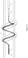
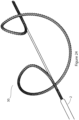
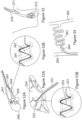
- the coil due to its resiliently deformable configuration) can self-adjust to allow continuous circumferential engagement while maintaining outward radial force along sections of vein or vessels with varying diameters and tortuous bends ( Fig.59 ).
- the coil comprises a shape memory material and is configured to adopt the coiled configuration when deployed.
- the helical coil is generally sufficiently resiliently deformable to self-adjust to maintain a circumferential radial force against the wall of a body lumen of varying diameter as it travels along the body lumen.
- the helical coil is configured to reflexively self-adjust its diameter in response to variable vein diameters and variable axial forces during axial movement along the treatment zone while maintaining an outward radial force on the vein.
- proximal as applied to a helical coil refers to an end of the device that is closest to the introduction point - the term “distal” should be construed accordingly.
- the distal helical coil section is a right-handed helix and proximal helical coil section is a left-handed helix.
- the coil elements are co-axial.
- each coil element has the same diameter when deployed.
- the coil has two helical coil elements, for example a double helix.
- the coil has four helical coil elements.
- the coil or each coil element is helical and is configured to have a pitch of about 0.5 to 1.5 times the coil diameter in the coiled configuration when deployed.
- one of the helical coil elements is axially spaced from another coil element.
- the control arm (generally a distal end of the control arm) is bifurcated to provide distal control arms, each connected to one of the helical coils.
- the device may comprise separate control arms, for independent control of the two helical coils.
- the control arm of the distal helical coil typically passes axially through the proximal helical coil (through one, more or all of the coils making up the proximal helical coil).
- the proximal helical coil has a maximum diameter that is greater than the maximum diameter of the distal helical coil (for example, 1.5-4 times greater).
- the proximal helical coil has a maximum diameter that is less than the maximum diameter of the distal helical coil (for example 1.5 to 4 times less).
- the pitch of the proximal and distal coil elements is different.
- the distal and proximal helical coils are conical.
- the diameter of the helical coil increases in the proximal direction (i.e. towards the entry point of the device).
- the coil or each coil is configured to have a diameter in the coiled configuration when deployed that is at least equal to or greater than the diameter of the vein to be treated.
- the or each helical coil is conical (i.e. the diameter of the coil increases or decreases as it approaches the device entry point - i.e. proximally).
- the diameter of the helical coil increases in the proximal direction.
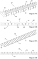
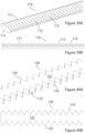
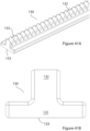
- the coil has a profile selected from circular, oval, curved, convex, concave, T-shaped, inverted T-shaped, or any other shape.
- the coil has a flat internal surface, and an external surface that is curved, concave, convex, or inverted T-shaped. Helical coils having these profiles are illustrated in Figs 34 to 41 .
- the roughened surface of the coil or each coil element is formed by treating the surface of the coil, typically an external body lumen facing surface of the coil (and/or a lateral surface of the coil), to introduce surface roughness.
- surface roughness is produced by mechanical, electrical, chemical abrasion, or abrasion by other means.
- the external surface of the coil comprises indentations configured to provide the roughened surface.
- the transverse indentations are disposed on each side of the external surface (i.e. when the external surface of the coil is concave).
- the helical coil has an inverted T-shape profile, in which the teeth from the leg of the inverted T shape.
- the coil comprises lateral teeth.
- the coil is formed from a flat wire with a diamond textured and roughened outer surface and a smooth inner surface.
- the coil has grooves or pores to act as reservoirs for therapeutic agents.
- the coil or each coil element comprises a core wire and the abrasive surface is formed by a second wire wound helically around the core wire to form a second coil.
- the second wire has a polygonal cross-section.
- the second coil has a pitch of 1 to 5 mm.
- a pitch of the second coil is greater at a proximal end thereof.
- a pitch of the second coil is lesser at a proximal end thereof.
- the second coil is bonded to the core wire, typically at a plurality of locations.
- a surface of the second wire is treated to introduce surface roughness.
- the helical coil has a proximal section that is generally co-axial with a longitudinal axis of the helical coil.
- the helical coil has a distal section that is generally co-axial with a longitudinal axis of the helical coil.
- control arm for the body lumen denuding head is disposed within the catheter member.
- control arm is connected to a proximal end of the coil.
- the control arm may be a hypotube, for example a hypotube formed from stainless steel, polymer or another material.
- control arm is configured for axial movement to deploy the body lumen denuding head at a target location in a body, and withdraw the body lumen denuding head into the catheter member after treatment.
- a distal end of the coil comprises an atraumatic head, for example a flexible material or a spherical ball.
- the device comprises a handle operatively connected to a proximal end of the catheter member and configured to control the deployment and retraction of the coil.
- the handle comprises a control element configured for axial adjustment of the control arm or arms without rotation.
- the handle comprises a control element configured for rotational adjustment of the control arm or arms.
- the device is configured for adjustment between:
- the method comprises treating a section of the body lumen having a length of at least 2, 4, 6, 8, 10, 12, 14, 16, 18 or 20 cm.
- the method is for completely occluding a body lumen, for example a vein or an artery.
- the method is for partially occluding a body lumen, for example a vein or an artery.
- the device may be employed to treat conditions or indications characterised by dysregulated or unwanted blood volume or flow rate through a section of the vasculature, by employing the device of the invention to partially occlude the section of the vasculature.
- the method is to thicken the wall of a vein by inducing significant wall thickening such as circumferential intimal hyperplasia.
- This effect "arterialises” a vein making it more resilient to the effect of higher blood pressure and shear forces.
- This thickening effect should be self-limiting when it occurs in response to a once off mechanical stimulus as opposed to the uncontrolled intimal hyperplasia that occurs when veins are exposed to persistently higher shear forces when used as conduits in the arterial system.
- the device may be employed to prepare a vein prior to grafting into the arterial circulatory system.
- the body lumen may be vasculature, for example an artery or vein.
- the method is a method of treating a varicose vein by denuding a section of the superior rectal artery.
- the method a method of thrombectomy by denuding a section of a vein or artery occluded by thrombus.
- the method is as a preparation step to prime a target area of an artery prior to grafting to reduce risk of Type 1 endoleaks.
- the body lumen being treated is a pelvic vein.
- the vessel is a varicose vein
- the method is typically a method of treating the varicose vein by denuding a lumen of the vein to cause occlusion of the varicose vein.
- the method is performed using an imaging modality such as ultrasound guidance.
- the radially expansible treatment element is a coil and preferably a resiliently deformable coil.
- body lumen means a cavity in the body, and may be an elongated cavity such as a vessel (i.e. an artery, vein, lymph vessel, urethra, ureter, sinus, auditory canal, nasal cavity, bronchus, fallopian tube, spermatic duct) or an annular space in the heart such as the left atrial appendage, left ventricular outflow tract, the aortic valve, the mitral valve, mitral valve continuity, tricuspid valve, pulmonary valve, or heart valve, or venous valve, or valve opening.
- the body lumen is a vasculature (i.e. a vein or artery or an arterio-venous vessel).
- the term "elongated catheter member” should be understood to mean an elongated body having a distal end that is operably connected to the body lumen denuding body.
- the catheter member comprises a control arm (for example a tubular member) operably connected to the denuding body for control thereof.
- the control arm may take any form, for example, a rod, wire, or tubular member such as a hypotube.
- the control arm and denuding body are axially adjustable relative to the catheter member.
- the denuding body is generally uncoiled and stowed in a distal end of the catheter member during delivery and withdrawal. Axial adjustment of the control arm relative to the catheter body results in deployment of the denuding body in its coiled configuration.
- Transluminal delivery means delivery of the body lumen denuding body to a target site (for example a varicose vein) through a body lumen, for example delivery through an artery, vein, or the gastrointestinal tract.
- the term "coil” should be understood to mean a loop-shaped element that is adjustable from an uncoiled configuration suitable for retraction into a catheter member and coiled configuration that in use is capable of circumferentially engaging and impressing its surface against a body lumen (i.e. engage the internal lumen of the vein along at least one full turn of the coil).
- the coil in its coiled configuration is generally circular, but may also be oval, square, triangular, or rectangular, as long as it is capable of circumferentially engaging an inner wall of the body lumen. As most veins and arteries have a circular, or almost circular, profile, a circular coil is preferred, as the radial force exerted by the coil in its deployed configuration is spread evenly around the wall of the body lumen.
- the diameter of the coil (or the maximum diameter in the case of helical coils whose diameter varies along its length) is generally at least about 5% greater than the diameter of the body lumen to be treated, for example at least 10%, 15%, 20%, 25% or 30% the diameter of the body lumen to be treated, and typically from 5-30% greater. It is important that the coil is oversized along at least one turn of the coil, and typically oversized along 1-2 turns.
- the coil may be formed from an elongated element, typically a single elongated element, for example a wire or filament.
- helical coil is sufficiently resiliently deformable for the coil diameter to adjust to varying diameter of the vein while maintaining a denuding radial force against the circumference of the body lumen.
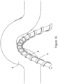
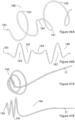
- the helical coil is typically sufficiently resiliently deformable to allow the coil pass through constrictions or valves in veins, as illustrated in Figs. 56 and 57 , respectively.
- These constrictions or changes in vein diameter over the treatment length may be either static (wider diameter of proximal vessel tapering to narrower distal vessel) or dynamic (contraction of vein wall smooth muscle leading to reduced vein diameter in a physiological process known as venospasm).
- the reducing vein diameter will increase the radial forces on the helical coil, this will in turn increase the hoop force generated within the material of the helical coil which will translate as a longitudinal force to increase the length of the coil.
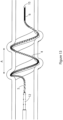
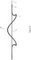
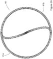
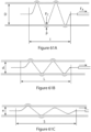
- This concept is illustrated in Fig 60 where the device is shown deployed in a typical vessel over a length I and diameter D.
- the radial force is equivalent to the pressure P acting perpendicular to the vein wall.
- the pressure that the vessel exerts on the oversized coil or hoop force (HF) is acting to compress the coil and increases when the diameter of the vessel is reduced to d. Due to the open helical coil design this increased hoop force will translate longitudinally to lengthen the coil to a length L.
- the coil has two helical coil elements, for example a double helix. Typically, each of the two helical coil elements has at least 0.5 turns when deployed, and typically from 0.5 to 1.0 turns or 0.5 to 0.7 turns. In one embodiment, the coil has three helical coil elements, for example a triple helix. Typically, each of the three helical coil elements has at least 0.3 turns when deployed, and typically from 0.3 to 1.0 turns or about 0.3 to 0.5 turns, when deployed. In one embodiment, the coil has four helical coil elements. Typically, each of the four helical coil elements has at least 0.25 turns when deployed, and typically from 0.25 to 0.75 turns when deployed. In one embodiment, the plurality of coil elements are connected together at their distal ends (closed configuration). In one embodiment, the plurality of coil elements are unconnected at their distal ends (open configuration).
- non-detachably attached to the catheter member as applied to the body lumen (or vessel or vein) denuding head should be understood to mean that the device is not configured to detachment and release of the head from the catheter member in the body; in other words, the device is not configured to implantation of the body lumen denuding head in the body.
- Implantable devices are undesirable for use in the treatment of superficial venous disease for the following reasons;
- Superficial leg veins are located relatively close to the skin surface where they can be easily palpated to touch.
- Bulky implantable devices can potentially cause pain, irritation or local skin deformity;
- Implants may inhibit the ability of the vein to reduce its diameter by contraction of smooth muscle known as venospasm. This is important in reducing vein diameter, reducing the amount of thrombus within the vein and preventing recanalisation; Implants may cause immune mediated inflammatory reactions.
- the body lumen engaging surface of at least part of the coil is abrasive for shearing or irreversibly damaging an inner lining of the body lumen away from the body lumen.
- the surface may be treated chemically, electrically or physically/mechanically to make it abrasive.
- machining There are several types of machining that can be adopted in order to roughen the surface including mechanical abrasion, shot blasting, sand blasting, knurling, electrical discharge machining, and pulse electrochemical machining. Chemical etching can also be used to roughen the surface of the part.
- the surface may be serrated.
- the surface could also include raised portions that when contacting the vessel lumen act as an abrasive surface, these raised portions could be pieces bonded to the surface of the abrasive surface or sections that are folded up from the abrasive surface, or pitted indentations that have a grating effect.
- One way of providing a helical coil having an abrasive surface is to wrap a second wire, or multiple wires, helically around a core wire as described below and shown in the figures.
- the second wire may have a round, flat, polygonal, triangular, square, rectangular, x-shaped, or star-shaped cross-section, so long as the combination of the elongated element (core wire) and the helically wound second wire create an abrasive lumen engaging surface capable of denuding the lumen when moved axially along the lumen in the deployed configuration.
- Wires may not be the only type of material wrapped around a central core wire or central housing, for example a polymer-based moulding, fins, abrasive granules, or spot welds.
- Another way of making a serrated surface is to score indentations in the surface of the coil, or to fabricate raised formations on the surface, for example helical indentations or formations.
- the surface should be abrasive enough so as to denude the lumen following a single longitudinal passage of the device to avoid the requirement of multiple passes which could be restricted by initial vasospasm.
- a preferred configuration includes surface elements to create both a macro and micro abrasive surface.
- the macro abrasive surface comprises grooves, indentations or teeth of at least about 0.5mm in height (for example. 0.5 to 1.0 mm) from peak to trough.
- the micro surface comprises grooves, indentations or teeth of about 5 to 100 microns in height from peak to trough. These grooves cause abrasion and prevent clogging of the abrasive surface by cellular debris over the treatment length.
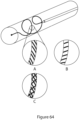
- the orientation of the macro abrasive grooves is important as they should not be parallel but perpendicular to the axial direction of withdrawal. This is illustrated in Figure 64 which shows a device deployed in a vessel. A detailed view of the coil surface is shown in the enlarged views (A),(B) and (C).
- (A) illustrates a groove pattern perpendicular to the vessel wall on withdrawal which is effective for causing mechanical ablation.
- (B) shows an orientation that lies parallel to the vein wall during withdrawal and is less effective. Due to the variability in vessel diameter and tortuosity in venous anatomy a macro-abrasive texture pattern in required to overcome this problem.
- (C) illustrates a diamond knurled pattern which is ideal to ensure part of the macro abrasive surface is always perpendicular to the vein wall during engagement when the device is withdrawn axially.
- the micro abrasive surface may have a surface roughness or RA value typically between 0.8 and 3.2 to achieve endothelial disruption and prevent excessive static friction.
- the RA value is the arithmetic average of the absolute values of the profile height deviations from the mean line, recorded within the evaluation length.
- An RA value of 0.8 corresponds to average peak to trough heights of 4 ⁇ m.
- Endothelial Cells (ECs) are protected in most vessels from direct exposure to flowing blood by an acellular layer known as the glycocalyx. This gel like structure is typically of thickness 0.5-3 ⁇ m, exceeding that of the ECs ( 0.2 - 2.0 ⁇ m) themselves.
- the term "shape memory material” should be understood to mean a material, typically a metal alloy, that remembers its original shape and that when deformed or forced into a different configuration, returns to its pre-deformed shape when deformation forces are released.
- An example is Nitinol.
- the coil, or the core element of the coil is formed from a shape memory material. Methods for making the coil from a shape memory material generally involve the steps wrapping the shape memory alloy around a die or heat setting fixture so it forms the desired shape post heat setting, placing the loaded fixture into an oven for a set temperature/time and the removing and cooling the piece. It is also possible to form the shape from a cylindrical piece of tubing that is laser cut to the desired size. It may also possible to fabricate this shape memory by other means, for example electro activated polymers.
- treatment zone as applied to a body lumen, vessel or superficial vein refers to a cylindrical section of a body lumen that is involved in the pathogenesis of a disease state and is typically 1cm or greater in length.
- treatment zone should be understood to mean a cylindrical section of the lumen of the superficial vein that fails to circulate blood effectively, and is typically 1cm or greater in length.
- the treatment zone is 1-50cm, 1-40cm, 1-30cm, 1-25cm, 1-15cm, 1-10cm, 5-50cm, 5-40cm, 5-30cm, 5-25cm, 5-15cm, 5-10cm, 10-50cm, 10-40cm, 10-30cm, 10-25cm, or 10-15cm, in length.
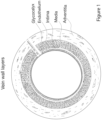
- veins comprise of 3 primary cellular layers: an outer adventitia layer made up of tough fibrous tissue and unmyelinated nerve fibres, a media layer made up of collagen and smooth muscle cells and an inner endothelial layer comprised of a single layer of squamous cells and some connective tissue.
- the endothelial layer is covered by the acellular glycocalyx which is typically an evenly distributed structure of thickness 0.5-3 ⁇ m.
- Veins have thinner walls than arteries and are less rigid and more compliant. Unlike arteries which retain their cylindrical shape at all times, veins can empty of blood and collapse down or alternatively stretch significantly to accommodate increased volumes of blood.
- Vein spasm or constriction occurs in response to physical stretch activating nerves on the outside of the vein wall. Constriction also occurs when chemicals such as endothelin-1 are released by the endothelium in response to stretch or disruption.
- the endothelial layer prevents blood from clotting in veins. If the endothelium is disrupted or damaged, pro-thrombotic factors are exposed which platelets will immediately adhere to and the clotting cascade will begin. Over time (4-12 weeks, typically an average of 8 weeks) clot within a vein becomes fibrotic as it is invaded by surrounding cells which deposit fibrin and collagen in a process known as sclerosis or fibrotic transformation. This prevents blood reflux in the vein and thus successfully treats the varicose vein.
- the aim of the device is to disrupt the endothelial and media layers of the vein but not the outer adventitia layer. This requires selective controlled mechanical disruption to a depth of at least 5 ⁇ m and up to but not exceeding 100 ⁇ m. This ensures endothelial and superficial medial layer disruption without deeper media/adventitial disruption which can lead to pain and/or perforation. There may be further cell death in deeper layers due to intracellular content release causing apoptosis in adjacent cells and continuing in a cascade over time to a depth of up to 300 ⁇ m. The resultant thrombosis or clot and fibrous scar tissue prevents blood from entering the vein and thus the appearance and symptoms associated with varicose veins.
- the attached thrombus created by the invention is confined to the superficial vein and as there is no blood flow it cannot be carried into the deep system where it can cause complications.
- the present invention achieves complete circumferential endothelial damage by its oversized coiled configuration with abrasive surface. It also causes media layer damage by at least three separate mechanisms. Firstly, the abrasive polygonal coil surface can penetrate to over 50 ⁇ m allowing damage to occur deeper than the intima layer. This could also be further increased by the use of more than one coil allowing the second abrasive coil, located more distally on the device, to penetrate deeper into the vessel wall section that has already been denuded by a coil more proximally on the device. This could also be achieved by repeating the procedure over the same treatment length using the same device.
- the risk of vein rupture and/or snagging of the device is proportional to the abrasiveness or sharpness of the device in contact with the wall causing frictional or cutting forces respectively and the depth that the abrasive elements penetrate into the wall. Snagging is a commonly reported pain point for physicians and patients following the use of current mechanochemical devices. There are even documented cases where the vein was snagged and stripped out inadvertently leading to pain and haematoma formation known as "inadvertent spontaneous stripping" [6]. Vein valve leaflets also represent an obstacle where a mechanical tip can become stuck and lead to snagging.
- the key problem therein is the difficulty in completely removing the endothelial layer and partially damaging the media layer without causing excessive resistance and/or snagging.
- Figure 2 highlights the importance of circumferential coverage in terms of endothelial cell destruction. It is taken from a partially treated vein in our animal study. The upper right corner shows a clot adherent to the vein wall with tissue invasion as it starts to become fibrotic at 28 days post procedure. The lower left corner has intact endothelium remaining. No clot has formed and blood can flow in the channel leading to overall treatment failure in this segment. Conversely, Figure 3 illustrates the results of full endothelial coverage and damage at 28 days post procedure with adherent thrombus formation obliterating the entire vessel lumen preventing blood flow resulting in treatment success. Inflammatory cell migration from the adventitia into the thrombus can be identified on microscopic examination. This leads to fibrotic transformation of the thrombus and long-term occlusion.
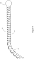
- the denuding head 3 comprises a helical coil 4 having a proximal end 5 and a distal end 6, which are generally co-axial with an axis of the helical coil, and a coiled part having about 1.5 rotations, an outer diameter of 13 mm, and a pitch of about 9 mm.
- the "oversized" diameter of the helical coil extends along at least one full loop of the coil (360 degrees). This feature, added to the oversized diameter of the coil relative to the vein, ensures that the coil engages and impresses circumferentially against the inner lumen of the vein, exerting radial pressure evenly around the full circumference of the vein. It is possible for the oversized diameter to extend along less than one full loop, for example at least 300 degrees, however this leads to a risk that the inner lumen of the vein will be incompletely denuded resulting in partial vein occlusion and subsequent recanalisation. In this embodiment, the coil has just over one complete turn, to allow complete coverage even when stretched while not being too long to cause increased friction against the vein wall and snagging.
- the coiled configuration and flexible material of the denuding head allows it to adapt to different vein diameters within a range of sizes which are smaller than the diameter of the coil while still exerting adequate radial force to cause denudation. These properties also enable the coil to adapt to changing vein diameters within the same vein over its target treatment length. These changes may be due to the natural tapering of the vein or due to venous valves. The latter can cause significant snagging and vein perforation if rigid structures become caught or trapped by the valve leaflets. Due to the flexible nature of the coil and minimal protrusions of the abrasive components this is unlikely to occur.
- the helical coil 4 has an abrasive surface configured to shear the inner lining of the vein (primarily but not limited to the endothelial cell layer) away from the vein when the helical coil is moved axially along the vein when in a deployed configuration.
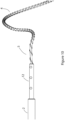
- the helical coil comprises a 0.01181" NITINOL core wire 8 and a second wire 9 helically wound around the core wire 8 forming an abrasive, serrated, surface on the helical coil 4.
- the second wire 9 is a flat wire that is formed from stainless Steel or Nitinol.
- the core wire 8 has a diameter of about 1 mm and the second wire 9 has width of about 0.7 mm and a thickness of about 0.02 mm.
- the pitch of the second wire is about 1.5mm.
- the pitch of the second wire 9 on the core wire 8 reduces at the distal end 6 of the helical coil 4, in this case to about 0.3 mm.
- the purpose of the smaller pitch/closed pitch at the distal end is to form a flexible distal member of the device to help navigate the device to the target anatomy.
- the pitch of the second wire 9 on the core wire 8 increases at the proximal end 5 of the helical coil 4, in this case to a maximum of about 3 mm.
- the purpose the higher pitch at the proximal end is to assist in the smooth recapture of the distal tip following the procedure.
- This proximal partition could also have a closed section with a lower, tighter pitch to aid recapture.
- the thickness of the second wire 9 is between 0.1 and 1 mm. Based on testing using equivalent animal venous tissue, a diameter of greater than 1 mm will carry the risk of creating a surface protrusion which can snag or stick to the vein wall surface.
- the proximal end 5 of the coil 4 is attached to a stainless steel hypotube 12 which extends through the catheter member 2 to a proximal end thereof (not shown).
- the hypotube 12 can be axially adjusted with respect to the catheter member 2 to effect deployment of the helical coil 4 distally of the catheter member into the coiled configuration, and retraction of the helical coil 4 into the catheter member during transluminal delivery and withdrawal of the device.
- the catheter member 2 is 4Fr polyimide extruded catheter tube, having an inwardly tapering mouth 14 in Figure 11 to assist in recapturing the helical coil 4 when it is retracted into the catheter member 2.
- the distal end of the helical coil 4 terminates in an atraumatic head, in this embodiment provided by a smooth metal ball 15, which serves to prevent the helical coil snagging on a vein or valve and reduce the risk of the distal tip causing perforation to the vein wall when it is deployed and withdrawn.
- the ball 15 is dimensioned to nest in the tapered mouth 14 in Figure 11 of the catheter member 2 when the device is in the delivery configuration.
- a surface of the second wire is scored with helical indentations 20 which serve to provide an abrasive, serrated, surface on the helical coil 4.
- the coil in both its undeployed and deployed configuration must be easily visualised on ultrasound to prevent inadvertent placement. This is achieved by incorporation of an echogenic section of material onto the tip of the catheter. In the deployed state the coil with its abrasive surface is inherently echogenic.
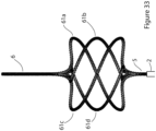
- Each coil element 41a, 41b has a proximal part that is generally coaxial with the catheter member, and a coiled part that in its deployed configuration comprises less than one full turn such the coil elements together adapt a double helix conformation that in use circumferentially engages the body lumen to be treated.
- each coil element comprises a core wire 8 having a second wire 9 wrapped around the core wire to provide a serrated body lumen denuding surface. The use of this embodiment, is the same as that described with reference to the previous embodiments.
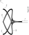
- a section of a helical coil 90 is illustrated having a generally convex profile with a convex external lumen-engaging surface 91 with indentations formed on the surface 91 providing diamond-shaped teeth 92 some with flat tips and some with pointed tips, and a smooth flat internal surface 93.
- Figures 49 to 51 illustrate a number of vein denuding heads forming part of devices of the invention, and in particular vein denuding heads have two unconnected helical coils axially spaced apart, in which parts described with reference to previous embodiments are assigned the same reference numerals.
- some coil deformation causing loss of contact is desirable to allow the coil to reduce static friction before the axial force becomes too high as to cause vessel wall damage or vein stripping.
- Vein stripping occurs when the distal tip of an intraluminal device acts like an anchor to transmit axial forces which are great enough to strip or remove an entire vein segment from the surrounding tissue. This has been documented with previous devices for vein ablation that have a non-deformable less elastic designs and causes significant pain and bruising for the patient as well as complicating the procedure [6].
- the venous network of the lower limbs is divided into three components: 1) superficial veins located in the superficial compartment superficial to the muscular fascia, draining the skin and subcutaneous tissue 2) deep veins that lie deep to the muscular fascia and drain the muscles of the lower limb, and 3) the perforating veins that penetrate the muscular fascia and connect the superficial and deep veins.
- Foam sclerosant preparations can propagate in clumped emulsions of sclerosant and air traveling into the deep venous system potentially damaging the endothelium and leading to DVT.
- Chemical sclerosants can also be inadvertently injected into subcutaneous tissue, nerves or arteries causing significant skin necrosis.
- a mechanical ablation device with the ability to be accurately deployed at a target site without the risk of uncontrolled forward propagation or damage to surrounding tissues is preferable for the treatment of lower limb venous reflux.
- the ability to recapture and reposition further reduces the risk of user related error.
- Bioabsorbable implant techniques have also previously failed to provide long term venous occlusion with recanalisation occurring following absorption [15].
- the authors have discovered that by using a purely mechanical non implantable solution, the natural thrombotic occlusion acts like an "implant" and is converted by the bodies natural healing mechanisms into a permanent occlusion in a process known as fibrotic transformation of thrombus.
- a method for treating smaller length incompetent tribuatry veins which commonly exist below the knee are currently treated with a procedure known as phlebectomy. This involves making a stab skin incision under local anaesthetic and using a vein hook device to manually extract the short vein segment. This procedure is often performed on multiple vein segments in the leg. It can be painful and uncomfortable for patients due to the requirement for multiple needlestick injections of local anaesthetic and the difficulty in fully anaesthetising each vein segment. Often due to unacceptable patient discomfort or physician preference, chemical sclerosant is used instead. The increased number of injections of chemical sclerosant can increase the risk of systemic toxic side effects and local complications including skin necrosis from inadvertent injection of sclerosant into the subcutaneous tissue or arterial system.
- the method of treating small tributary veins is performed with a miniaturised helical coil as illustrated in Figures 66 and 67 .
- the mechanism of action provided by this embodiment is the same as previously described for the treatment of large veins such as the GSV.
- a miniaturised coil with abrasive outer surface is deployed exerting a radial force on the vein wall. This surface denudes the inner layer upon withdrawal.
- the helical coil is loaded around the needle as part of an intravenous cannula.
- Modifying the current arrangement of an intravenous 14G cannula to decrease the size of the needle used for entering the vein while maintaining the outer diameter of the sheath at 2.1 mm allows accommodation of the helical coil as illustrated in Figure 65 .
- Creating a more tapered tip with the polyurethane outer catheter would allow skin access.
- the miniaturised coil section could be deployed by partial withdrawal of the outer polyurethane cannulae ( Figure 66 ).
- the outer cannula can be used for recapture and atraumatic removal of the coil.
- This proposed technique reduces the need for local anaesthesia as stab skin incisions are not required nor is any traction on the vein required to pull out the vein as in hook phlebectomy procedures. There is also no requirement for chemical sclerosant reducing the associated risks of skin necrosis.
- the vein is accessed with a small gauge needle and a guidewire is passed into the vein.
- An outer sheath similar to an introducer sheath is passed over the guidewire as illustrated in Figure 69 .
- This outer sheath is manufactured to contain the coil adherent to its inner lining just below the aperture at the tip. This allows the guidewire to pass through and past the coil within the introducer.
- the coil is then deployed by partial withdrawal of the outer sheath Figure 68 .
- the coil is deployed by using a peel-away introducer sheath as shown in Figure 70 .
- the coil can be reloaded into the sheath and used on separate veins.
- PCS is characterized by visible congestion of the pelvic veins on venography in women with a history of chronic pelvic pain for more than six months. Most commonly the left ovarian vein is the cause of reflux and pelvic varicosities. Morbidity associated with PCS can be severe leading to a significant reduction in quality of life and patient discomfort. PCS manifests with different intra-pelvic symptoms including non-cyclical pain, urinary frequency and dyspareunia.
- the method may be employed for the treatment of pelvic vein reflux in which a helical coil device is used to mechanically denude the internal iliac and or ovarian veins to cause permanent occlusion.
- This occlusion will prevent venous reflux to the leg veins which causes recurrent varicose veins, the venous territories supplying the vagina/vulva and venous territories involved in PCS.
- the denudation procedure can be combined with temporary balloon occlusion to reduce blood flow and promote adherence of thrombus to the treated section of vein. This could be especially beneficial in pelvic veins with higher volume reflux and velocity.
- the procedure could be enhanced by the combined use of chemical sclerosant and/or embolisation particles.
- Figure 71 is a schematic showing the venous anatomy relating to the pelvic vein reflux and the use of a helical coil to denude the internal iliac veins and prevent refluxing flow to the venous territories involved thus curing symptoms.
- Deep vein reflux caused by incompetent venous valves involving the femoral vein in the lower limb cannot be treated by ablation and occlusion as it is vital for circulatory return of blood from the limb to the heart.
- Some incompetent venous valves have been obliterated by DVT but other are maintain normal valve leaflets but due to wall laxity they no longer opppose correctly to prevent reflux.
- Current methods of treatment involve invasive surgical procedures to create neovalves. Accordingly, there is a need for a less invasive procedure to restore venous valve function.
- the method may be employed for the treatment of deep vein reflux in which the helical coil device is deployed and withdrawn across an existing valve.
- the outer surface is mildly abrasive to reduce the risk of thrombotic occlusion while maintaining the ability to disrupt the endothelial layer. This causes hypertrophy of the valve leaflets and surrounding tissue with the effect of bringing the valve leaflets closer together and restoring the one-way valve function to prevent reflux.
- haemorrhoids can be treated with pelvic vein embolisation.
- Newer techniques also target the specific occlusion of the superior rectal artery to prevent filling of the dilated venous plexus causing the internal haemorrhoids [17].
- This artery is between 3 and 5mm in diameter in most instances.
- improved treatments are required.
- the method is for treating hemorrhoids in which a helical coil device is used to mechanically denude the superior rectal artery to cause permanent occlusion and prevent filling of the venous plexus thus curing the condition.
- the method may be employed for the treatment of varicoceles in which a single use helical coil is used to mechanically denude the testicular vein to cause permanent occlusion.
- Figure 55 is a schematic showing the venous anatomy and the related procedure to cause permanent vein occlusion.
- FIG. 53A is a schematic representation of portal vein occlusion using a non-implant mechanical denudation method.
- Coronary artery bypass graft (CABG) surgery is the standard of care for patients with left main coronary artery disease (CAD) and three-vessel CAD.
- Peripheral artery bypass grafting (PABG) surgery is performed in patients with late-stage peripheral artery occlusive disease.
- the internal mammary artery is commonly used for revascularization in coronary bypass surgery, however, veins (almost exclusively the great saphenous vein) remain the most commonly used grafts, especially for PABG surgery.
- the interposition of vein grafts into the arterial system exposes the vein to higher stretch forces and shear stress which may result in excessive inflammatory changes within the venous wall known as intimal hyperplasia leading to occlusion and vein graft failure.
- a way to increase the long-term success rates of vein grafts for arterial disease is an important clinical need and may be achieved by preconditioning or modifying the vein graft prior to use as a conduit in the arterial system.
- a method for the pre-treatment of veins to be used as grafts in the arterial system for the treatment of CAD and PAD is proposed.
- a helical coil with a less abrasive surface or partially abrasive surface is provided to cause vein wall thickening without complete thrombotic occlusion and subsequent fibrosis.
- the depth of vein wall disruption must be specific to develop the correct inflammatory response which does not predispose the vein to graft failure.
- Aterio-venous (AV) Fistula Aterio-venous (AV) Fistula
- a helical coil with reduced abrasiveness or partially abrasive is used prior to the surgery for creation of the anastomosis to produce a vein with a healthy pattern of remodelling. This procedure should ideally be performed 4 to 12 weeks in advance of AVF creation to allow cellular changes to occur and subside.
- a method for using a helical coil with abrasive inner and leading-edge surfaces to dislodge thrombus from the vessel wall without causing endothelial trauma.
- Figure 73 shows how such a device can remove thrombus while leaving the endothelial surface intact and less likely to re-thrombose.
- the device is deployed distal to the thrombotic occlusion and withdrawn proximally towards the access site.
- a fogarty balloon recapturing basket or aspiration catheter can be used to remove the thrombus from the circulation. This will restore blood flow and prevent the sequelae of vessel occlusion occuring.
- Percutaneous stenting of the vasculature is commonly performed to reinstate blood flow in partially stenosed or occluded arterial or venous circulation.
- In-stent thrombosis is a relatively uncommon but potentially life threatening complication occurring after approximately 1% of cardiac stent procedures.
- Stents placed in diseased arteries may have struts overlying calcified or atheromatous plaques. Elevated stents struts in these situations can lead to a failure of coverage by the neointima especially in drug eluting stents [20]. This typically manifests as late or very late onset stent thrombosis over 1 year following implantation.
- a helical coil with an outer abrasive surface that covers part of the coil circumference is provided. This allows selective treatment of a section of arterial surface which is likely to remain uncovered following statement.
- Figure 74 illustrates the method of using a partial abrasive coil to selectively pre-treat a section of artery prior to stent placement. This increases the likelihood of stent strut coverage by the neointima and reduces the risk of late stent restenosis.
- Imaging technologies such as intravascular ultrasound (IVUS) can be used to orientate the device and allow the operator to selectively target a desired section of vessel wall.
- IVUS intravascular ultrasound
- Uterine fibroids are benign lesions which can cause significant pelvic pain and dysmenorrhea. They can be treated by hysterectomy or with minimally invasive embolisation of the uterine arteries supplying the fibroid.
- embolic agents for uterine artery embolisation are polyvinyl alcohol (PVA), tris-acryl gelatin microspheres, and polyzene-F hydrogel microspheres.
- Complications include migration of embolic material to non-target tissues, excessive necrosis causing pain and infection. Accordingly, there is a need for a less invasive, non-implantable treatment with lower complication rates for the treatment of uterine fibroids.
- Abdominal aortic aneurysms are abnormal dilatations of the aorta which can be complicated by rupture causing significant morbidity and mortality.
- Treatment for large aneurysms is aimed at reducing the risk of rupture.
- Treatment options are either open surgery with graft placement or endovascular aneurysm repair using large covered stent grafts (EVAR).
- EVAR is a less invasive procedure with significantly faster recovery time and lower risk of renal injury.
- endoleaks can be classified as Type I to Type V.
- Type I endoleaks occur at the proximal or distal graft attachment sites. Blood enters through gaps between the vessel wall and the graft and fills the sac leading to a risk of rupture.
- Type II endoleaks occur when retrograde flow occurs into the aneurysmal sac via side branches from lumbar or mesenteric vessels and also leads to a risk of rupture.
- Type I and II endoleaks account for the majority of morbidity associated with the EVAR post-operative course.
- Current treatment methods for Type I endoleaks include miniature screws and additional stent graft placements. Type II endoleaks can be treated with embolisation coil placement in the lumbar or mesenteric vessels supplying the sac.
- a method for preparing sections of the aorta close to graft attachment sites to reduce the risk of Type I endoleaks is performed by using a helical coil to denude the endothelial lining in these specific locations whose locations can be easily determined based on preoperative imaging planning.
- the arterial wall is primed to develop a neointimal proliferation at the graft attachment site and reduce the risk of blood leakage and Type I endoleaks.
- Duodenal Mucosal resurfacing is a new technique that has been shown to improve blood glucose control in diabetic patients in early clinical studies [24].
- the duodenum is an important conduit for glucose absorption and signalling to endocrine organs. It is thought that the duodenal mucosa becomes hyperplastic in response to chronic high sugar diets which creates an insulin-resistant signal, worsening glucose control. By ablating this hyperplastic mucosa, a new mucosal surface can regenerate without harmful signalling.
- the anatomy of the duodenum shares some important characteristics with the venous system. It has a tortuous curved pathway, it is highly compliant and distensible and muscular wall contractions can cause constriction. The aim of treatment is to safely ablate only the superficial mucosal layer without affecting the deeper muscularis layer below. This is performed over the length of the duodenum of approximately 10cms.
- a secondary effect could be to ablate the areas of the ileum colonised by adherent bacteria to allow regeneration of normal or non-colonised mucosa.
- This method could be used in conjunction with antibiotic therapy to enhance the effect and lower the high recurrence rates.
- a similar method could be used to tighten the gastro-oesphageal junction which can be the cause of gastric reflux in the presence of sphincter laxity.
- Female sterilisation is commonly performed by fallopian tube ligation when permanent contraception is desired by the patient.
- Current methods range from open surgical ligation, salpingectomy and minimally invasive clip placement. Complications of these procedures include pain, bleeding and infection.
- a less invasive reliable method which avoids surgical resection or permanent implantation is required.
- a radial expansive helical device is inserted, deployed and withdrawn in the fallopian tube. This disrupts the endothelial and subendothelial layers initiating an inflammatory response causing fibrotic occlusion of the fallopian tube over time. This technique could also be applied to male sterilisation procedures on the lumen of the vas deferens.
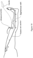
- spermatic vein insufficiency or varicocele
- a device of the invention is advanced along a left internal spermatic vein 270, and the helical coil 271 is deployed into circumferential contact with the vein 270 and retracted to denude the lumen of the vessel, causing thrombus formation and occlusion of the vessel 270, thereby occluding the vein and treating the condition.
- a radial expandable element which contacts the vessel wall at discrete distant points is used to measure the response of the endothelium to chemical or mechanical stimuli.
- Mechanical stimuli can be provided by the radial force of the device itself which can be static or modifiable via a control arm.
- Chemical stimuli can be provided by coating of pharmacological agents on the device surface.
- piezoelectric sensors are incorporated into the radial expansive element to measure pressure and flow effects on the coil during intraluminal procedures.
- An expansive element within a vein lumen generating an outward radial force will cause a hoop force (HF) within the vessel wall. This stretching HF will cause an opposing compressive hoop force within the intra luminal device.
- HF hoop force
Landscapes
- Health & Medical Sciences (AREA)
- Life Sciences & Earth Sciences (AREA)
- Surgery (AREA)
- Engineering & Computer Science (AREA)
- Public Health (AREA)
- Biomedical Technology (AREA)
- Heart & Thoracic Surgery (AREA)
- Animal Behavior & Ethology (AREA)
- General Health & Medical Sciences (AREA)
- Veterinary Medicine (AREA)
- Medical Informatics (AREA)
- Molecular Biology (AREA)
- Nuclear Medicine, Radiotherapy & Molecular Imaging (AREA)
- Vascular Medicine (AREA)
- Reproductive Health (AREA)
- Rheumatology (AREA)
- Cardiology (AREA)
- Plasma & Fusion (AREA)
- Otolaryngology (AREA)
- Physics & Mathematics (AREA)
- Biophysics (AREA)
- Pulmonology (AREA)
- Anesthesiology (AREA)
- Hematology (AREA)
- Surgical Instruments (AREA)
Priority Applications (1)
| Application Number | Priority Date | Filing Date | Title |
|---|---|---|---|
| EP24207057.1A EP4509072A3 (en) | 2018-05-18 | 2019-05-20 | A device for denuding a body lumen |
Applications Claiming Priority (2)
| Application Number | Priority Date | Filing Date | Title |
|---|---|---|---|
| EP18173170 | 2018-05-18 | ||
| PCT/EP2019/062998 WO2019219975A1 (en) | 2018-05-18 | 2019-05-20 | A device for denuding a body lumen |
Related Child Applications (1)
| Application Number | Title | Priority Date | Filing Date |
|---|---|---|---|
| EP24207057.1A Division EP4509072A3 (en) | 2018-05-18 | 2019-05-20 | A device for denuding a body lumen |
Publications (3)
| Publication Number | Publication Date |
|---|---|
| EP3793459A1 EP3793459A1 (en) | 2021-03-24 |
| EP3793459C0 EP3793459C0 (en) | 2024-07-10 |
| EP3793459B1 true EP3793459B1 (en) | 2024-07-10 |
Family
ID=62217798
Family Applications (2)
| Application Number | Title | Priority Date | Filing Date |
|---|---|---|---|
| EP19730654.1A Active EP3793459B1 (en) | 2018-05-18 | 2019-05-20 | A device for denuding a body lumen |
| EP24207057.1A Pending EP4509072A3 (en) | 2018-05-18 | 2019-05-20 | A device for denuding a body lumen |
Family Applications After (1)
| Application Number | Title | Priority Date | Filing Date |
|---|---|---|---|
| EP24207057.1A Pending EP4509072A3 (en) | 2018-05-18 | 2019-05-20 | A device for denuding a body lumen |
Country Status (13)
| Country | Link |
|---|---|
| US (4) | US11903570B2 (enExample) |
| EP (2) | EP3793459B1 (enExample) |
| JP (2) | JP7759726B2 (enExample) |
| KR (1) | KR102709316B1 (enExample) |
| CN (1) | CN112218591B (enExample) |
| AU (1) | AU2019270520B2 (enExample) |
| CA (1) | CA3095704A1 (enExample) |
| ES (1) | ES2983997T3 (enExample) |
| IE (1) | IE87658B1 (enExample) |
| IL (2) | IL278706B2 (enExample) |
| MX (1) | MX2020012388A (enExample) |
| PL (1) | PL3793459T3 (enExample) |
| WO (1) | WO2019219975A1 (enExample) |
Families Citing this family (19)
| Publication number | Priority date | Publication date | Assignee | Title |
|---|---|---|---|---|
| WO2018185255A1 (en) * | 2017-04-05 | 2018-10-11 | National University Of Ireland, Galway | An implantable medical device |
| US20230397925A1 (en) * | 2020-11-06 | 2023-12-14 | Bard Peripheral Vascular, Inc. | Balloon catheter with selective scoring capability |
| WO2022177893A1 (en) | 2021-02-16 | 2022-08-25 | Boston Scientific Scimed, Inc. | Tissue resurfacing devices and methods thereof |
| EP4395663A1 (en) * | 2021-08-31 | 2024-07-10 | Incumedx Inc. | Embolic device with improved neck coverage |
| US12478424B2 (en) | 2021-09-10 | 2025-11-25 | Biosense Webster (Israel) Ltd. | Staggered pairs of biased ablation electrodes on basket catheter |
| US12440263B2 (en) | 2022-01-20 | 2025-10-14 | Biosense Webster (Israel) Ltd. | Systems and methods for tripodic spines forming a spherical basket for improved tissue contact and current delivery |
| US12484961B2 (en) | 2022-01-20 | 2025-12-02 | Biosense Webster (Israel) Ltd. | Mechanical retainer systems for electrodes of a basket catheter, and methods of the same |
| US12446946B2 (en) | 2022-01-20 | 2025-10-21 | Biosense Webster (Israel) Ltd. | Systems and methods for a single spiral electrode assembly forming a spherical basket for improved tissue contact and current delivery |
| US12471989B2 (en) | 2022-04-28 | 2025-11-18 | Biosense Webster (Israel) Ltd. | Strengthened expandable baskets for medical probes and medical probes containing strengthen expandable baskets |
| WO2023232252A1 (en) * | 2022-06-02 | 2023-12-07 | Clearstream Technologies Limited | Catheter for forming a fistula |
| EP4565150A4 (en) * | 2022-08-08 | 2025-12-10 | Crossfire Medical Inc | SEGMENTAL VASCULAR ABLATION |
| US12533185B2 (en) | 2022-12-28 | 2026-01-27 | Biosense Webster (Israel) Ltd. | Basket end effector with distal position sensor |
| US12004771B1 (en) | 2023-06-27 | 2024-06-11 | Cardio Flow, Inc. | Rotational atherectomy devices and methods |
| WO2025048791A1 (en) * | 2023-08-29 | 2025-03-06 | Bard Peripheral Vascular, Inc. | Coil shaped vein closure device with cooling and heating capability |
| US12370078B2 (en) | 2023-10-27 | 2025-07-29 | NEXT Life Sciences, Inc. | Apparatus and method for delivery and/or removal of occlusions in the body |
| WO2025122700A1 (en) * | 2023-12-05 | 2025-06-12 | The Regents Of The University Of California | System and method for minimally invasive tubal sterilization |
| CN117838066B (zh) * | 2024-03-07 | 2024-05-17 | 首都医科大学附属北京友谊医院 | Evar术后支架相关并发症风险预测方法和系统 |
| KR20250155730A (ko) * | 2024-04-24 | 2025-10-31 | 경희대학교 산학협력단 | 하지정맥 수술시 정맥 내벽의 기계 화학적 절제장치 |
| US12478399B1 (en) * | 2024-12-23 | 2025-11-25 | Invera Medical Limited | Method of treating a blood vessel in a subject |
Family Cites Families (42)
| Publication number | Priority date | Publication date | Assignee | Title |
|---|---|---|---|---|
| US5306244A (en) * | 1984-05-14 | 1994-04-26 | Surgical Systems & Instruments, Inc. | Method of guidewire insertion |
| US4935025A (en) * | 1989-01-30 | 1990-06-19 | Bundy Mark A | Transluminal lysing device |
| US5011489A (en) | 1989-10-05 | 1991-04-30 | University Of South Florida | Endothelium stripper and method of using the same |
| US6702811B2 (en) * | 1999-04-05 | 2004-03-09 | Medtronic, Inc. | Ablation catheter assembly with radially decreasing helix and method of use |
| US6402745B1 (en) * | 2000-02-23 | 2002-06-11 | Peter J. Wilk | Intravenous whip electrode for vein ablation |
| US7517352B2 (en) * | 2000-04-07 | 2009-04-14 | Bacchus Vascular, Inc. | Devices for percutaneous remote endarterectomy |
| US8298257B2 (en) * | 2000-06-29 | 2012-10-30 | Concentric Medical, Inc. | Systems, methods and devices for removing obstructions from a blood vessel |
| WO2002007795A2 (en) * | 2000-07-24 | 2002-01-31 | Jeffrey Grayzel | Stiffened balloon catheter for dilatation and stenting |
| US6500186B2 (en) * | 2001-04-17 | 2002-12-31 | Scimed Life Systems, Inc. | In-stent ablative tool |
| US7862575B2 (en) | 2003-05-21 | 2011-01-04 | Yale University | Vascular ablation apparatus and method |
| US20050085836A1 (en) * | 2003-09-12 | 2005-04-21 | Jean Raymond | Methods and devices for endothelial denudation to prevent recanalization after embolization |
| US20050080448A1 (en) * | 2003-09-18 | 2005-04-14 | Kear Jason W. | Medical retrieval devices and related methods of use |
| IL161928A0 (en) * | 2004-05-11 | 2005-11-20 | Pikus Valery | Instrument and method for cosmetic removal of superficial varicose veins |
| US20060085054A1 (en) * | 2004-09-09 | 2006-04-20 | Zikorus Arthur W | Methods and apparatus for treatment of hollow anatomical structures |
| WO2006044670A1 (en) * | 2004-10-14 | 2006-04-27 | Crossman Arthur W | Vascular catheter device and related method of using the same |
| US20090209987A1 (en) * | 2005-02-01 | 2009-08-20 | Mathews Eric D | Snare with capture-area enhancement |
| US20070239199A1 (en) * | 2006-03-31 | 2007-10-11 | Swaminathan Jayaraman | Inferior vena cava filter |
| US9017361B2 (en) * | 2006-04-20 | 2015-04-28 | Covidien Lp | Occlusive implant and methods for hollow anatomical structure |
| WO2009021071A2 (en) * | 2007-08-06 | 2009-02-12 | Henson Michael R | Thrombectomy system and method |
| WO2009109967A1 (en) | 2008-03-02 | 2009-09-11 | V.V.T. Medical Ltd. | Method and device for vein ablation |
| CN102112063A (zh) * | 2008-06-06 | 2011-06-29 | 瓦里克斯医疗公司 | 静脉治疗装置和方法 |
| JP2013544133A (ja) * | 2010-10-25 | 2013-12-12 | メドトロニック アーディアン ルクセンブルク ソシエテ ア レスポンサビリテ リミテ | 腎ニューロモジュレーションのためのマルチ電極アレイを有するカテーテル装置ならびに関連のシステムおよび方法 |
| US9585667B2 (en) | 2010-11-15 | 2017-03-07 | Vascular Insights Llc | Sclerotherapy catheter with lumen having wire rotated by motor and simultaneous withdrawal from vein |
| US8795319B2 (en) * | 2011-03-02 | 2014-08-05 | Cook Medical Technologies Llc | Embolization coil |
| US20130338689A1 (en) * | 2012-06-15 | 2013-12-19 | Gadal Consulting, LLC | Device and method for removing unwanted material in a vascular conduit |
| US20140277003A1 (en) * | 2013-03-13 | 2014-09-18 | The Spectranetics Corporation | Material Capturing Guidewire |
| KR102333433B1 (ko) | 2013-03-15 | 2021-12-02 | 내셔널 유니버시티 오브 아일랜드, 갈웨이 | 색전술 시스템 |
| US10105159B2 (en) * | 2013-03-15 | 2018-10-23 | W.L. Gore Associates, Inc | Recanalization device |
| EP3202340B1 (en) * | 2013-03-15 | 2024-07-17 | Vetex Medical Ltd. | A device suitable for removing matter from inside the lumen and the wall of a body lumen |
| US10660645B2 (en) * | 2013-03-15 | 2020-05-26 | Embo Medical Limited | Embolization systems |
| WO2014201434A2 (en) * | 2013-06-14 | 2014-12-18 | Artventive Medical Group, Inc. | Implantable luminal devices |
| GB2519057A (en) | 2013-08-02 | 2015-04-15 | Martin Sabado | Minimally invasive device and method for treating vascular disorders |
| EP3054857B1 (en) | 2013-10-13 | 2020-09-09 | V.V.T. Med Ltd. | Vein ablation device |
| US20160030068A1 (en) | 2014-07-31 | 2016-02-04 | Terumo Kabushiki Kaisha | Method for treating varicose veins and intraluminal device used in such method |
| US20160030719A1 (en) | 2014-07-31 | 2016-02-04 | Terumo Kabushiki Kaisha | Method for treating varicose veins and intraluminal device used in such method |
| US20160030023A1 (en) | 2014-07-31 | 2016-02-04 | Terumo Kabushiki Kaisha | Method for treating varicose veins and intraluminal device used in such method |
| JP6732403B2 (ja) * | 2014-10-03 | 2020-07-29 | テルモ株式会社 | 医療デバイス |
| JP2016073401A (ja) * | 2014-10-03 | 2016-05-12 | テルモ株式会社 | 医療デバイス |
| GB201511595D0 (en) | 2014-12-23 | 2015-08-19 | Whiteley Mark | Medical device for treating a vein |
| JP2016168173A (ja) * | 2015-03-12 | 2016-09-23 | テルモ株式会社 | 血管処置方法 |
| EP3135206B1 (de) | 2015-08-31 | 2020-01-15 | Gefässpraxis Dr. Erpen AG | Vorrichtung zur behandlung der varikose |
| US20190133592A1 (en) | 2016-05-13 | 2019-05-09 | Swiss Vx Venentherapie Und Forschung Gmbh | Non-implant device for temporary occlusion of blood vessels and use thereof |
-
2019
- 2019-05-20 MX MX2020012388A patent/MX2020012388A/es unknown
- 2019-05-20 US US16/416,838 patent/US11903570B2/en active Active
- 2019-05-20 IL IL278706A patent/IL278706B2/en unknown
- 2019-05-20 ES ES19730654T patent/ES2983997T3/es active Active
- 2019-05-20 PL PL19730654.1T patent/PL3793459T3/pl unknown
- 2019-05-20 EP EP19730654.1A patent/EP3793459B1/en active Active
- 2019-05-20 US US17/056,040 patent/US20210077144A1/en not_active Abandoned
- 2019-05-20 EP EP24207057.1A patent/EP4509072A3/en active Pending
- 2019-05-20 AU AU2019270520A patent/AU2019270520B2/en active Active
- 2019-05-20 IL IL312524A patent/IL312524A/en unknown
- 2019-05-20 IE IE20200258A patent/IE87658B1/en unknown
- 2019-05-20 JP JP2020564654A patent/JP7759726B2/ja active Active
- 2019-05-20 CA CA3095704A patent/CA3095704A1/en active Pending
- 2019-05-20 CN CN201980033262.9A patent/CN112218591B/zh active Active
- 2019-05-20 WO PCT/EP2019/062998 patent/WO2019219975A1/en not_active Ceased
- 2019-05-20 KR KR1020207033115A patent/KR102709316B1/ko active Active
-
2021
- 2021-12-10 US US17/547,723 patent/US12207807B2/en active Active
-
2024
- 2024-07-05 US US18/764,722 patent/US20250114084A1/en active Pending
-
2025
- 2025-07-11 JP JP2025117289A patent/JP2025137623A/ja active Pending
Also Published As
| Publication number | Publication date |
|---|---|
| IL312524A (en) | 2024-07-01 |
| IE87658B1 (en) | 2025-09-24 |
| CN112218591B (zh) | 2025-02-14 |
| US20220133286A1 (en) | 2022-05-05 |
| AU2019270520B2 (en) | 2025-02-20 |
| KR20210013557A (ko) | 2021-02-04 |
| US12207807B2 (en) | 2025-01-28 |
| KR102709316B1 (ko) | 2024-09-25 |
| JP2025137623A (ja) | 2025-09-19 |
| US11903570B2 (en) | 2024-02-20 |
| EP3793459C0 (en) | 2024-07-10 |
| JP2021524314A (ja) | 2021-09-13 |
| US20190350567A1 (en) | 2019-11-21 |
| AU2019270520A1 (en) | 2020-10-22 |
| US20210077144A1 (en) | 2021-03-18 |
| IL278706B2 (en) | 2024-10-01 |
| PL3793459T3 (pl) | 2025-01-13 |
| ES2983997T3 (es) | 2024-10-28 |
| US20250114084A1 (en) | 2025-04-10 |
| CA3095704A1 (en) | 2019-11-21 |
| WO2019219975A1 (en) | 2019-11-21 |
| JP7759726B2 (ja) | 2025-10-24 |
| BR112020021542A2 (pt) | 2021-01-19 |
| EP4509072A2 (en) | 2025-02-19 |
| CN112218591A (zh) | 2021-01-12 |
| MX2020012388A (es) | 2021-04-28 |
| IL278706A (enExample) | 2021-01-31 |
| EP4509072A3 (en) | 2025-04-16 |
| IL278706B1 (en) | 2024-06-01 |
| EP3793459A1 (en) | 2021-03-24 |
| IE20200258A1 (en) | 2019-11-21 |
Similar Documents
| Publication | Publication Date | Title |
|---|---|---|
| US12207807B2 (en) | Devices and methods for treating a vessel in a subject | |
| AU2020239753B2 (en) | Embolisation systems | |
| US11684371B2 (en) | Embolization systems | |
| RU2814884C2 (ru) | Устройство для денудации просвета полости организма | |
| BR112020021542B1 (pt) | Dispositivo para desnudamento de um lúmen corporal |
Legal Events
| Date | Code | Title | Description |
|---|---|---|---|
| STAA | Information on the status of an ep patent application or granted ep patent |
Free format text: STATUS: UNKNOWN |
|
| STAA | Information on the status of an ep patent application or granted ep patent |
Free format text: STATUS: THE INTERNATIONAL PUBLICATION HAS BEEN MADE |
|
| PUAI | Public reference made under article 153(3) epc to a published international application that has entered the european phase |
Free format text: ORIGINAL CODE: 0009012 |
|
| STAA | Information on the status of an ep patent application or granted ep patent |
Free format text: STATUS: REQUEST FOR EXAMINATION WAS MADE |
|
| 17P | Request for examination filed |
Effective date: 20201102 |
|
| AK | Designated contracting states |
Kind code of ref document: A1 Designated state(s): AL AT BE BG CH CY CZ DE DK EE ES FI FR GB GR HR HU IE IS IT LI LT LU LV MC MK MT NL NO PL PT RO RS SE SI SK SM TR |
|
| AX | Request for extension of the european patent |
Extension state: BA ME |
|
| DAV | Request for validation of the european patent (deleted) | ||
| DAX | Request for extension of the european patent (deleted) | ||
| RIC1 | Information provided on ipc code assigned before grant |
Ipc: A61B 17/12 20060101ALN20230717BHEP Ipc: A61B 17/3207 20060101ALI20230717BHEP Ipc: A61B 17/3205 20060101AFI20230717BHEP |
|
| GRAP | Despatch of communication of intention to grant a patent |
Free format text: ORIGINAL CODE: EPIDOSNIGR1 |
|
| STAA | Information on the status of an ep patent application or granted ep patent |
Free format text: STATUS: GRANT OF PATENT IS INTENDED |
|
| RIC1 | Information provided on ipc code assigned before grant |
Ipc: A61B 17/12 20060101ALN20230731BHEP Ipc: A61B 17/3207 20060101ALI20230731BHEP Ipc: A61B 17/3205 20060101AFI20230731BHEP |
|
| INTG | Intention to grant announced |
Effective date: 20230831 |
|
| GRAJ | Information related to disapproval of communication of intention to grant by the applicant or resumption of examination proceedings by the epo deleted |
Free format text: ORIGINAL CODE: EPIDOSDIGR1 |
|
| STAA | Information on the status of an ep patent application or granted ep patent |
Free format text: STATUS: REQUEST FOR EXAMINATION WAS MADE |
|
| GRAS | Grant fee paid |
Free format text: ORIGINAL CODE: EPIDOSNIGR3 |
|
| STAA | Information on the status of an ep patent application or granted ep patent |
Free format text: STATUS: GRANT OF PATENT IS INTENDED |
|
| GRAP | Despatch of communication of intention to grant a patent |
Free format text: ORIGINAL CODE: EPIDOSNIGR1 |
|
| INTC | Intention to grant announced (deleted) | ||
| RIC1 | Information provided on ipc code assigned before grant |
Ipc: A61B 17/12 20060101ALN20240116BHEP Ipc: A61B 17/3207 20060101ALI20240116BHEP Ipc: A61B 17/3205 20060101AFI20240116BHEP |
|
| INTG | Intention to grant announced |
Effective date: 20240130 |
|
| GRAA | (expected) grant |
Free format text: ORIGINAL CODE: 0009210 |
|
| STAA | Information on the status of an ep patent application or granted ep patent |
Free format text: STATUS: THE PATENT HAS BEEN GRANTED |
|
| AK | Designated contracting states |
Kind code of ref document: B1 Designated state(s): AL AT BE BG CH CY CZ DE DK EE ES FI FR GB GR HR HU IE IS IT LI LT LU LV MC MK MT NL NO PL PT RO RS SE SI SK SM TR |
|
| REG | Reference to a national code |
Ref country code: CH Ref legal event code: EP |
|
| REG | Reference to a national code |
Ref country code: DE Ref legal event code: R096 Ref document number: 602019054969 Country of ref document: DE |
|
| U01 | Request for unitary effect filed |
Effective date: 20240806 |
|
| U07 | Unitary effect registered |
Designated state(s): AT BE BG DE DK EE FI FR IT LT LU LV MT NL PT SE SI Effective date: 20240820 |
|
| REG | Reference to a national code |
Ref country code: ES Ref legal event code: FG2A Ref document number: 2983997 Country of ref document: ES Kind code of ref document: T3 Effective date: 20241028 |
|
| PG25 | Lapsed in a contracting state [announced via postgrant information from national office to epo] |
Ref country code: NO Free format text: LAPSE BECAUSE OF FAILURE TO SUBMIT A TRANSLATION OF THE DESCRIPTION OR TO PAY THE FEE WITHIN THE PRESCRIBED TIME-LIMIT Effective date: 20241010 |
|
| PG25 | Lapsed in a contracting state [announced via postgrant information from national office to epo] |
Ref country code: GR Free format text: LAPSE BECAUSE OF FAILURE TO SUBMIT A TRANSLATION OF THE DESCRIPTION OR TO PAY THE FEE WITHIN THE PRESCRIBED TIME-LIMIT Effective date: 20241011 |
|
| PG25 | Lapsed in a contracting state [announced via postgrant information from national office to epo] |
Ref country code: IS Free format text: LAPSE BECAUSE OF FAILURE TO SUBMIT A TRANSLATION OF THE DESCRIPTION OR TO PAY THE FEE WITHIN THE PRESCRIBED TIME-LIMIT Effective date: 20241110 |
|
| PG25 | Lapsed in a contracting state [announced via postgrant information from national office to epo] |
Ref country code: HR Free format text: LAPSE BECAUSE OF FAILURE TO SUBMIT A TRANSLATION OF THE DESCRIPTION OR TO PAY THE FEE WITHIN THE PRESCRIBED TIME-LIMIT Effective date: 20240710 |
|
| PG25 | Lapsed in a contracting state [announced via postgrant information from national office to epo] |
Ref country code: RS Free format text: LAPSE BECAUSE OF FAILURE TO SUBMIT A TRANSLATION OF THE DESCRIPTION OR TO PAY THE FEE WITHIN THE PRESCRIBED TIME-LIMIT Effective date: 20241010 |
|
| PG25 | Lapsed in a contracting state [announced via postgrant information from national office to epo] |
Ref country code: RS Free format text: LAPSE BECAUSE OF FAILURE TO SUBMIT A TRANSLATION OF THE DESCRIPTION OR TO PAY THE FEE WITHIN THE PRESCRIBED TIME-LIMIT Effective date: 20241010 Ref country code: NO Free format text: LAPSE BECAUSE OF FAILURE TO SUBMIT A TRANSLATION OF THE DESCRIPTION OR TO PAY THE FEE WITHIN THE PRESCRIBED TIME-LIMIT Effective date: 20241010 Ref country code: IS Free format text: LAPSE BECAUSE OF FAILURE TO SUBMIT A TRANSLATION OF THE DESCRIPTION OR TO PAY THE FEE WITHIN THE PRESCRIBED TIME-LIMIT Effective date: 20241110 Ref country code: HR Free format text: LAPSE BECAUSE OF FAILURE TO SUBMIT A TRANSLATION OF THE DESCRIPTION OR TO PAY THE FEE WITHIN THE PRESCRIBED TIME-LIMIT Effective date: 20240710 Ref country code: GR Free format text: LAPSE BECAUSE OF FAILURE TO SUBMIT A TRANSLATION OF THE DESCRIPTION OR TO PAY THE FEE WITHIN THE PRESCRIBED TIME-LIMIT Effective date: 20241011 |
|
| PG25 | Lapsed in a contracting state [announced via postgrant information from national office to epo] |
Ref country code: SM Free format text: LAPSE BECAUSE OF FAILURE TO SUBMIT A TRANSLATION OF THE DESCRIPTION OR TO PAY THE FEE WITHIN THE PRESCRIBED TIME-LIMIT Effective date: 20240710 |
|
| PG25 | Lapsed in a contracting state [announced via postgrant information from national office to epo] |
Ref country code: CZ Free format text: LAPSE BECAUSE OF FAILURE TO SUBMIT A TRANSLATION OF THE DESCRIPTION OR TO PAY THE FEE WITHIN THE PRESCRIBED TIME-LIMIT Effective date: 20240710 |
|
| PG25 | Lapsed in a contracting state [announced via postgrant information from national office to epo] |
Ref country code: SK Free format text: LAPSE BECAUSE OF FAILURE TO SUBMIT A TRANSLATION OF THE DESCRIPTION OR TO PAY THE FEE WITHIN THE PRESCRIBED TIME-LIMIT Effective date: 20240710 |
|
| PLBE | No opposition filed within time limit |
Free format text: ORIGINAL CODE: 0009261 |
|
| STAA | Information on the status of an ep patent application or granted ep patent |
Free format text: STATUS: NO OPPOSITION FILED WITHIN TIME LIMIT |
|
| 26N | No opposition filed |
Effective date: 20250411 |
|
| PGFP | Annual fee paid to national office [announced via postgrant information from national office to epo] |
Ref country code: PL Payment date: 20250516 Year of fee payment: 7 |
|
| U20 | Renewal fee for the european patent with unitary effect paid |
Year of fee payment: 7 Effective date: 20250531 |
|
| PGFP | Annual fee paid to national office [announced via postgrant information from national office to epo] |
Ref country code: GB Payment date: 20250520 Year of fee payment: 7 Ref country code: ES Payment date: 20250606 Year of fee payment: 7 |
|
| PGFP | Annual fee paid to national office [announced via postgrant information from national office to epo] |
Ref country code: IE Payment date: 20250520 Year of fee payment: 7 |
|
| REG | Reference to a national code |
Ref country code: CH Ref legal event code: H13 Free format text: ST27 STATUS EVENT CODE: U-0-0-H10-H13 (AS PROVIDED BY THE NATIONAL OFFICE) Effective date: 20251223 |
|
| PG25 | Lapsed in a contracting state [announced via postgrant information from national office to epo] |
Ref country code: CH Free format text: LAPSE BECAUSE OF NON-PAYMENT OF DUE FEES Effective date: 20250531 |
|
| PG25 | Lapsed in a contracting state [announced via postgrant information from national office to epo] |
Ref country code: MC Free format text: LAPSE BECAUSE OF FAILURE TO SUBMIT A TRANSLATION OF THE DESCRIPTION OR TO PAY THE FEE WITHIN THE PRESCRIBED TIME-LIMIT Effective date: 20240710 |
|
| PG25 | Lapsed in a contracting state [announced via postgrant information from national office to epo] |
Ref country code: RO Free format text: LAPSE BECAUSE OF FAILURE TO SUBMIT A TRANSLATION OF THE DESCRIPTION OR TO PAY THE FEE WITHIN THE PRESCRIBED TIME-LIMIT Effective date: 20240710 |