EP3792992B1 - Battery module comprising module housing - Google Patents
Battery module comprising module housing Download PDFInfo
- Publication number
- EP3792992B1 EP3792992B1 EP19885255.0A EP19885255A EP3792992B1 EP 3792992 B1 EP3792992 B1 EP 3792992B1 EP 19885255 A EP19885255 A EP 19885255A EP 3792992 B1 EP3792992 B1 EP 3792992B1
- Authority
- EP
- European Patent Office
- Prior art keywords
- frame
- battery
- male
- female coupling
- battery assembly
- Prior art date
- Legal status (The legal status is an assumption and is not a legal conclusion. Google has not performed a legal analysis and makes no representation as to the accuracy of the status listed.)
- Active
Links
- 230000008878 coupling Effects 0.000 claims description 87
- 238000010168 coupling process Methods 0.000 claims description 87
- 238000005859 coupling reaction Methods 0.000 claims description 87
- 238000003466 welding Methods 0.000 claims description 22
- 239000000853 adhesive Substances 0.000 claims description 8
- 230000001070 adhesive effect Effects 0.000 claims description 8
- 238000004519 manufacturing process Methods 0.000 description 10
- 238000000034 method Methods 0.000 description 9
- PXHVJJICTQNCMI-UHFFFAOYSA-N Nickel Chemical compound [Ni] PXHVJJICTQNCMI-UHFFFAOYSA-N 0.000 description 6
- 238000007789 sealing Methods 0.000 description 6
- WHXSMMKQMYFTQS-UHFFFAOYSA-N Lithium Chemical compound [Li] WHXSMMKQMYFTQS-UHFFFAOYSA-N 0.000 description 5
- 229910052744 lithium Inorganic materials 0.000 description 5
- 229910000831 Steel Inorganic materials 0.000 description 4
- 239000012777 electrically insulating material Substances 0.000 description 4
- 239000000463 material Substances 0.000 description 4
- 239000010959 steel Substances 0.000 description 4
- 238000003860 storage Methods 0.000 description 4
- 230000008602 contraction Effects 0.000 description 3
- 239000003792 electrolyte Substances 0.000 description 3
- 238000009434 installation Methods 0.000 description 3
- 229910052759 nickel Inorganic materials 0.000 description 3
- 230000004308 accommodation Effects 0.000 description 2
- 239000012790 adhesive layer Substances 0.000 description 2
- 239000004020 conductor Substances 0.000 description 2
- 238000007599 discharging Methods 0.000 description 2
- 230000000694 effects Effects 0.000 description 2
- 230000006870 function Effects 0.000 description 2
- 239000010410 layer Substances 0.000 description 2
- 229910052751 metal Inorganic materials 0.000 description 2
- 239000002184 metal Substances 0.000 description 2
- 239000007773 negative electrode material Substances 0.000 description 2
- 239000007774 positive electrode material Substances 0.000 description 2
- 238000003825 pressing Methods 0.000 description 2
- 239000010935 stainless steel Substances 0.000 description 2
- 229910001220 stainless steel Inorganic materials 0.000 description 2
- RYGMFSIKBFXOCR-UHFFFAOYSA-N Copper Chemical compound [Cu] RYGMFSIKBFXOCR-UHFFFAOYSA-N 0.000 description 1
- UFHFLCQGNIYNRP-UHFFFAOYSA-N Hydrogen Chemical compound [H][H] UFHFLCQGNIYNRP-UHFFFAOYSA-N 0.000 description 1
- 229910052782 aluminium Inorganic materials 0.000 description 1
- XAGFODPZIPBFFR-UHFFFAOYSA-N aluminium Chemical compound [Al] XAGFODPZIPBFFR-UHFFFAOYSA-N 0.000 description 1
- OJIJEKBXJYRIBZ-UHFFFAOYSA-N cadmium nickel Chemical compound [Ni].[Cd] OJIJEKBXJYRIBZ-UHFFFAOYSA-N 0.000 description 1
- 239000003575 carbonaceous material Substances 0.000 description 1
- 229910052802 copper Inorganic materials 0.000 description 1
- 239000010949 copper Substances 0.000 description 1
- 230000003247 decreasing effect Effects 0.000 description 1
- 238000004146 energy storage Methods 0.000 description 1
- PCHJSUWPFVWCPO-UHFFFAOYSA-N gold Chemical compound [Au] PCHJSUWPFVWCPO-UHFFFAOYSA-N 0.000 description 1
- 229910052737 gold Inorganic materials 0.000 description 1
- 239000010931 gold Substances 0.000 description 1
- 230000017525 heat dissipation Effects 0.000 description 1
- 229910052739 hydrogen Inorganic materials 0.000 description 1
- 239000001257 hydrogen Substances 0.000 description 1
- 230000003446 memory effect Effects 0.000 description 1
- 239000000178 monomer Substances 0.000 description 1
- QELJHCBNGDEXLD-UHFFFAOYSA-N nickel zinc Chemical compound [Ni].[Zn] QELJHCBNGDEXLD-UHFFFAOYSA-N 0.000 description 1
- 230000005855 radiation Effects 0.000 description 1
- 238000004904 shortening Methods 0.000 description 1
- 238000007086 side reaction Methods 0.000 description 1
Images


Classifications
-
- H—ELECTRICITY
- H01—ELECTRIC ELEMENTS
- H01M—PROCESSES OR MEANS, e.g. BATTERIES, FOR THE DIRECT CONVERSION OF CHEMICAL ENERGY INTO ELECTRICAL ENERGY
- H01M50/00—Constructional details or processes of manufacture of the non-active parts of electrochemical cells other than fuel cells, e.g. hybrid cells
- H01M50/20—Mountings; Secondary casings or frames; Racks, modules or packs; Suspension devices; Shock absorbers; Transport or carrying devices; Holders
- H01M50/244—Secondary casings; Racks; Suspension devices; Carrying devices; Holders characterised by their mounting method
-
- H—ELECTRICITY
- H01—ELECTRIC ELEMENTS
- H01M—PROCESSES OR MEANS, e.g. BATTERIES, FOR THE DIRECT CONVERSION OF CHEMICAL ENERGY INTO ELECTRICAL ENERGY
- H01M50/00—Constructional details or processes of manufacture of the non-active parts of electrochemical cells other than fuel cells, e.g. hybrid cells
- H01M50/20—Mountings; Secondary casings or frames; Racks, modules or packs; Suspension devices; Shock absorbers; Transport or carrying devices; Holders
- H01M50/204—Racks, modules or packs for multiple batteries or multiple cells
- H01M50/207—Racks, modules or packs for multiple batteries or multiple cells characterised by their shape
- H01M50/209—Racks, modules or packs for multiple batteries or multiple cells characterised by their shape adapted for prismatic or rectangular cells
-
- H—ELECTRICITY
- H01—ELECTRIC ELEMENTS
- H01M—PROCESSES OR MEANS, e.g. BATTERIES, FOR THE DIRECT CONVERSION OF CHEMICAL ENERGY INTO ELECTRICAL ENERGY
- H01M10/00—Secondary cells; Manufacture thereof
- H01M10/60—Heating or cooling; Temperature control
- H01M10/65—Means for temperature control structurally associated with the cells
- H01M10/653—Means for temperature control structurally associated with the cells characterised by electrically insulating or thermally conductive materials
-
- H—ELECTRICITY
- H01—ELECTRIC ELEMENTS
- H01M—PROCESSES OR MEANS, e.g. BATTERIES, FOR THE DIRECT CONVERSION OF CHEMICAL ENERGY INTO ELECTRICAL ENERGY
- H01M50/00—Constructional details or processes of manufacture of the non-active parts of electrochemical cells other than fuel cells, e.g. hybrid cells
- H01M50/20—Mountings; Secondary casings or frames; Racks, modules or packs; Suspension devices; Shock absorbers; Transport or carrying devices; Holders
- H01M50/204—Racks, modules or packs for multiple batteries or multiple cells
- H01M50/207—Racks, modules or packs for multiple batteries or multiple cells characterised by their shape
- H01M50/211—Racks, modules or packs for multiple batteries or multiple cells characterised by their shape adapted for pouch cells
-
- H—ELECTRICITY
- H01—ELECTRIC ELEMENTS
- H01M—PROCESSES OR MEANS, e.g. BATTERIES, FOR THE DIRECT CONVERSION OF CHEMICAL ENERGY INTO ELECTRICAL ENERGY
- H01M50/00—Constructional details or processes of manufacture of the non-active parts of electrochemical cells other than fuel cells, e.g. hybrid cells
- H01M50/20—Mountings; Secondary casings or frames; Racks, modules or packs; Suspension devices; Shock absorbers; Transport or carrying devices; Holders
- H01M50/249—Mountings; Secondary casings or frames; Racks, modules or packs; Suspension devices; Shock absorbers; Transport or carrying devices; Holders specially adapted for aircraft or vehicles, e.g. cars or trains
-
- H—ELECTRICITY
- H01—ELECTRIC ELEMENTS
- H01M—PROCESSES OR MEANS, e.g. BATTERIES, FOR THE DIRECT CONVERSION OF CHEMICAL ENERGY INTO ELECTRICAL ENERGY
- H01M50/00—Constructional details or processes of manufacture of the non-active parts of electrochemical cells other than fuel cells, e.g. hybrid cells
- H01M50/20—Mountings; Secondary casings or frames; Racks, modules or packs; Suspension devices; Shock absorbers; Transport or carrying devices; Holders
- H01M50/262—Mountings; Secondary casings or frames; Racks, modules or packs; Suspension devices; Shock absorbers; Transport or carrying devices; Holders with fastening means, e.g. locks
-
- H—ELECTRICITY
- H01—ELECTRIC ELEMENTS
- H01M—PROCESSES OR MEANS, e.g. BATTERIES, FOR THE DIRECT CONVERSION OF CHEMICAL ENERGY INTO ELECTRICAL ENERGY
- H01M2220/00—Batteries for particular applications
- H01M2220/20—Batteries in motive systems, e.g. vehicle, ship, plane
-
- Y—GENERAL TAGGING OF NEW TECHNOLOGICAL DEVELOPMENTS; GENERAL TAGGING OF CROSS-SECTIONAL TECHNOLOGIES SPANNING OVER SEVERAL SECTIONS OF THE IPC; TECHNICAL SUBJECTS COVERED BY FORMER USPC CROSS-REFERENCE ART COLLECTIONS [XRACs] AND DIGESTS
- Y02—TECHNOLOGIES OR APPLICATIONS FOR MITIGATION OR ADAPTATION AGAINST CLIMATE CHANGE
- Y02E—REDUCTION OF GREENHOUSE GAS [GHG] EMISSIONS, RELATED TO ENERGY GENERATION, TRANSMISSION OR DISTRIBUTION
- Y02E60/00—Enabling technologies; Technologies with a potential or indirect contribution to GHG emissions mitigation
- Y02E60/10—Energy storage using batteries
Definitions
- the present disclosure relates to a battery module including a module housing having a first frame and a second frame, and more particularly, to a battery module and a battery pack including a module housing with a simplified assembling process and an improved energy density.
- Secondary batteries currently commercialized include nickel cadmium batteries, nickel hydrogen batteries, nickel zinc batteries, lithium secondary batteries and so on.
- the lithium secondary batteries are more highlighted in comparison to nickel-based secondary batteries due to advantages such as free charging and discharging, caused by substantially no memory effect, very low self-discharge rate, and high energy density.
- the lithium secondary battery mainly uses lithium-based oxides and carbonaceous materials as a positive electrode active material and a negative electrode active material, respectively.
- the lithium secondary battery includes an electrode assembly in which a positive electrode plate coated with the positive electrode active material and a negative electrode plate coated with the negative electrode active material are disposed with a separator being interposed therebetween, and an exterior, namely a battery exterior, hermetically containing the electrode assembly together with an electrolyte.
- secondary batteries have been widely used not only in small-sized devices such as portable electronic devices but also in medium-sized or large-sized devices such as vehicles and power storage devices.
- the secondary batteries are used in the middle-sized or large-sized devices, a large number of secondary batteries are electrically connected to increase capacity and power.
- secondary batteries are widely used for the middle-sized or large-sized devices since they may be easily stacked.
- the conventional battery module generally includes a plurality of cartridges made of plastic in order to protect or fix a plurality of secondary batteries included therein in a stacked form.
- the cartridge made of plastic has low mechanical rigidity compared to a cartridge made of steel, so its internal components may be easily damaged when an external impact is applied to the battery module.
- the battery module having a plurality of cartridges with low thermal conductivity has seriously low heat dissipation efficiency, which makes it difficult to cool the battery module.
- the plurality of cartridges have many objects to be assembled, a lot of assembly time is required to manufacture a battery assembly, which may greatly increase the manufacturing cost. Moreover, the plurality of cartridges have a great volume, which lowers the energy density of the battery module.
- US20120244422 provides a battery case configured by fixing a joined portion where plate sections overlap with each other using a fixation member, and two different types of sealing members are disposed at the joined portion. It is possible to ensure high sealing properties by using sealing members suitable for the respective shapes of portions of the joined portion.
- CN102354774 relates to a battery power supply device, which comprises a left shell and a right shell. At least one battery pack is arranged on the internal side of the left shell.
- the battery pack consists of at least two monomer batteries which are serially connected. At least one battery pack is also correspondingly arranged on the internal side of the right shell.
- An air guide pipe is arranged on one side of the battery pack.
- a front finished circuit board and a rear finished circuit board are respectively arranged at the two ends of the battery pack.
- a front baffle is arranged on the external side of the front finished circuit board.
- a rear baffle is arranged on the external side of the rear finished circuit board.
- a negative terminal and a positive terminal penetrate through the front baffle or the rear baffle and then stretch out of the baffles.
- KR1020160049863 provides a structure for fixing a battery module, which comprises: a housing unit for fixing a cell laminated body on both sides, wherein a plurality of cells are laminated and arranged in a height direction; and a sensing block equipped with a sensing assembly connected to the cells, and directly coupled to the front and rear sides of the housing unit for fixing the housing unit on both sides.
- the coupling of the housing unit for fixing and supporting the cell laminated body on both sides can be formed through the sensing block.
- the sensing block has effects in improving an economic feasibility of a producing process and a rapidity of an assembling process by performing both a function of electrical connection to the cell laminated body and a function of mechanical coupling, without using an extra coupling member or a coupling factor.
- US5681668 discloses a battery shield for a storage battery including first and second members which are dimensioned to fit around the battery, forming a shield structure, that is open at its top and encloses the battery on all four sides and on the bottom, forming a heat shield for protecting the battery from hot temperatures, the first and second members being hinged to a common base and are adapted to be pivoted about respective hinges outwardly away from another to an open position to facilitate installation of a battery in the shield and to then be moved upwardly and toward one another, in the manner of a "clamshell", to a closed position for enclosing the battery within the battery shield, the bottom of the storage battery having a plurality of transverse channels therein extending between opposing sides for permitting air flow around the bottom of the storage battery when the battery is enclosed within the battery shield.
- EP2808921 discloses a battery module including: a plurality of aligned battery cells each including a terminal, and a casing for housing the battery cells.
- the casing comprises a pair of end plates each configured to face a wide surface of a battery cell at a respective outer end of the plurality of battery cells; side plates configured to support side surfaces of the battery cells at respective sides of the plurality of battery cells; a cover configured to cover the battery cells, and at least one of the side plates comprises a wall portion, an extension portion offset from the wall portion and a seating portion arranged to receive an end portion of the cover.
- the present disclosure is designed to solve the problems of the related art, and therefore the present disclosure is directed to providing a battery module and a battery pack including a module housing with a simplified assembling process and an improved energy density.
- the invention is a battery module, comprising:
- ends of the bent portions of the first frame are overlapped with ends of the bent portions of the second frame, respectively.
- a male-female coupling unit having a male-female coupling structure is respectively provided to the overlapped portions of the first frame and the second frame to restrict movement of the first frame and the second frame.
- a welding coupling unit may be respectively provided to the overlapped portions of the first frame and the second frame so that the first frame and the second frame are coupled to each other by welding.
- a fixing clip may be added to the male-female coupling unit so as to be fitted into the male-female coupling structure.
- the male-female coupling unit may have a fixing hole perforated in the male-female coupling structure of the first frame and the second frame, and a fixing bolt inserted through the fixing hole.
- At least one of the first frame and the second frame may have a guide protrusion formed at an inner surface thereof facing the battery assembly in an inwardly protruding form to press one side of the plurality of secondary batteries.
- a thermal conductive adhesive may be added to an inner surface of at least one of the first frame and the second frame so as to be bonded and fixed to the plurality of secondary batteries.
- an inner wall is formed at an inner side of the first frame or the second frame to extend from an inner upper portion to an inner lower portion thereof.
- a battery pack comprising two or more battery modules according to the present disclosure.
- a vehicle comprising the battery pack according to the present disclosure.
- the male-female coupling unit having the male-female coupling structure of a fitting manner to restrict movement of the first frame and the second frame relative to each other since the male-female coupling unit having the male-female coupling structure of a fitting manner to restrict movement of the first frame and the second frame relative to each other is provided, the first frame and the second frame may be simply fastened to press to each other by moving inward with each other. Accordingly, the manufacturing method of the battery module may be simplified, thereby greatly increasing the manufacturing efficiency.
- the battery module of the present disclosure may shorten the time required for the manufacturing process and increase the energy density of the battery module by omitting the use of a cartridge.
- the welding guide line helps the welding process of a worker and also allows the welding coupling unit to be formed more quickly at a portion of the module housing with a relatively smaller thickness, the time required for the manufacturing process may be shortened effectively.
- the welding coupling unit is formed separately in addition to the male-female coupling structure, the coupling force between the first frame and the second frame may be further enhanced.
- the fixing clip having the close fixing portion and the insert portion is separately added to the male-female coupling unit, it is possible to restrict movement of the male-female coupling structure of the male-female coupling unit in the front and rear direction and in the left and right direction, thereby effectively preventing the male-female coupling structure from being separated. Accordingly, the coupling of the male-female coupling structure of the male-female coupling unit may be more tightly maintained.
- the male-female coupling unit since the male-female coupling unit has the fixing hole and the fixing bolt, the movement of the male-female coupling structure of the male-female coupling unit in the vertical direction and in the horizontal direction may be restricted more strongly, thereby effectively preventing the male-female coupling structure from being separated.
- the guide protrusions is formed on the inner surface of at least one of the first frame and the second frame, the stacked arrangement of the plurality of secondary batteries of the battery assembly may be effectively maintained. Accordingly, it is possible to effectively prevent the secondary batteries from being damaged due to an impact generated during the movement of the battery module.
- the battery module of the present disclosure may prevent the first frame or the second frame from deforming in the vertical direction due to the expansion and contraction caused by charge and discharge of the battery assembly.
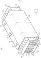
- FIG. 1 is a perspective view schematically showing a battery module according to an embodiment of the present disclosure.
- FIG. 2 is a side view schematically showing a pouch-type secondary battery, employed at the battery module according to an embodiment of the present disclosure.
- FIG. 3 is a front view schematically showing some components of the battery module according to an embodiment of the present disclosure in a separated state.
- a battery module 200 may include a battery assembly 210, a module housing 220, and a bus bar assembly 250.
- the battery assembly 210 may include a plurality of secondary batteries having electrode leads 111.
- the secondary battery 100 may be a pouch-type secondary battery 100.
- the pouch-type secondary battery 100 may include an electrode assembly (not shown), an electrolyte (not shown), and a pouch 120.
- the pouch 120 may include two pouches, namely a left pouch and a right pouch, at which an accommodation portion 115 having a concave form is formed.
- the electrode assembly and the electrolyte may be accommodated in the accommodation portion 115.
- each of the two pouches includes an outer insulating layer, a metal layer, and an inner adhesive layer, and the inner adhesive layers of the two pouches may be bonded to each other at edge portions of the pouch 120 to form a sealing portion.
- a terrace portion S may be formed at each of both ends of the pouch 120 at which a positive electrode lead 111a and a negative electrode lead 111b are formed.
- the electrode assembly (not shown) is an assembly of an electrode and a separator, and may be configured such that at least one positive electrode plate and at least one negative electrode plate are disposed with the separator interposed therebetween.
- a positive electrode tab is provided to a positive electrode plate of the electrode assembly, and at least one positive electrode tab may be connected to the positive electrode lead 111a.
- the positive electrode lead 111a has one end connected to the positive electrode tab and the other end exposed out of the pouch 120, and the exposed portion may serve as an electrode terminal of the secondary battery 100, for example a positive electrode terminal of the secondary battery 100.
- a negative electrode tab is provided to a negative electrode plate of the electrode assembly, and at least one negative electrode tab may be connected to the negative electrode lead 111b.
- the negative electrode lead 111b has one end connected to the negative electrode tab and the other end exposed out of the pouch, and the exposed portion may serve as an electrode terminal of the secondary battery 100, for example a negative electrode terminal of the secondary battery 100.
- the positive electrode lead 111a and the negative electrode lead 111b may be formed at both ends of the secondary battery 100 located at opposite sides relative to the center thereof. That is, the positive electrode lead 111a may be provided at one end based on the center of the secondary battery 100. In addition, the negative electrode lead 111b may be provided at the other end of the secondary battery 100 based on the center thereof.
- each secondary battery 100 may be configured such that the positive electrode lead 111a and the negative electrode lead 111b protrude forward and backward, respectively.
- the positive electrode lead 111a and the negative electrode lead 111b may be configured in a plate shape.
- the positive electrode lead 111a and the negative electrode lead 111b may protrude in a horizontal direction in a standing-up form where wide surfaces thereof are oriented to the left and to the right, respectively.
- the horizontal direction refers to a direction parallel to the ground when the battery module 200 is placed on the ground.
- each pouch-type secondary battery 100 may be arranged to stand up approximately perpendicular to the ground such that two wide surfaces are located at the left and right sides and the sealing portions are located at the upper and lower sides and the front and rear sides thereof.
- each secondary battery 100 may be configured to be erect vertically.
- the upper, lower, front, rear, left and right directions will be set based on the case when being observed in the F direction, unless specially stated otherwise.
- the battery module 200 according to the present disclosure may employ various kinds of secondary batteries known at the time of filing of this application, without being limited to the pouch-type secondary battery 100 described above.
- the battery assembly 210 may have a front side 220a, a rear side 220b, an upper side 220c, a lower side 220d, a left side 220e, and a right side 220f.
- the electrode leads 111 protruding forward and rearward may be formed at the front side 220a and the rear side 220b of the battery assembly 210.
- the sealing portions of the plurality of secondary batteries 100 may be located at the upper side 220c, the lower side 220d, the front side 220a and the rear side 220b of the battery assembly 210.
- the battery assembly 210 may be arranged such that the plurality of secondary batteries 100 are stacked in one direction (a left and right direction).
- the battery assembly 210 may be configured such that the plurality of pouch-type secondary batteries 100 are stacked in parallel to each other in the left and right direction.
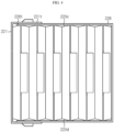
- FIG. 4 is a front view schematically showing some components of the battery module according to an embodiment of the present disclosure.
- the module housing 220 may include a first frame 221 and a second frame 226.
- FIGS. 3 and 4 show the process of coupling the first frame 221 and the second frame 226 of the module housing 220.
- the first frame 221 and the second frame 226 may include a steel material or stainless steel plated with an electrically insulating material. That is, since the steel or stainless material is excellent in thermal conductivity, it is possible to effectively release the heat generated from the battery assembly 210. Further, since the steel or stainless steel material has excellent mechanical rigidity, it is possible to effectively prevent the battery module 200 from being damaged due to an external impact.
- the first frame 221 may have a plate shape whose one surface is relatively wider than a side surface. Also, when viewed in the F direction, the first frame 221 may be located at the left side of the battery assembly 210. Moreover, in the first frame 221, both ends of the plate may be bent rightward to form bent portions 221t. In addition, the bent portions 221t may be located at the upper side 220c and the lower side 220d of the battery assembly 210, respectively.
- the first frame 221 may have a plate shape whose both ends are bent to the right.
- a left side of the first frame 221 may be located to closely contact the left side 220e of the battery assembly 210.
- the bent portions 221t at both ends of the first frame 221 may be located to surround at least a portion of the upper side 220c and the lower side 220d of the battery assembly 210, respectively.
- the second frame 226 may have a plate shape with one surface relatively wider than a side surface.
- a right side of the second frame 226 may be located at the right side of the battery assembly 210.
- both ends of the plate may be bent to the left to form bent portions 226t.
- the bent portions 226t may be located at the upper side 220c and the lower side 220d of the battery assembly 210, respectively.
- the bent portions 226t of the second frame 226 may be coupled with the bent portions 221t of the first frame 221.
- the second frame 226 may have a plate shape whose both ends are bent leftward. Also, the second frame 226 may be located to closely contact the right side 220f of the battery assembly 210. Further, the bent portions 226t at both ends of the second frame 226 may be located to surround at least a portion of the upper side 220c and the lower side 220d of the battery assembly 210, respectively.
- the module housing 220 may be configured such that ends of the bent portions 221t of the first frame 221 are overlapped with ends of the bent portions 226t of the second frame 226.
- ends of the first frame 221 and the second frame 226 may be overlapped with each other such that the bent portions 221t of the first frame 221 surround the outer sides of the bent portions 226t of the second frame 226.
- both ends (the bent portions) 221t, 226t of the first frame 221 and the second frame 226 may have different vertical widths from each other.
- the vertical width between both ends of the first frame 221 may be greater than the vertical width between both ends of the second frame 226.
- both ends 221t, 226t of the first frame 221 and the second frame 226 may be overlapped and fastened to each other while pressing each other.
- the battery module 200 of the present disclosure may shorten the time required for the manufacturing process and increase the energy density of the battery module 200 by omitting the use of a cartridge.
- first frame 221 and the second frame 226 may be configured to press the left side 220e and the right side 220f of the battery assembly 210 in an inner direction while being coupled to each other.
- the ⁇ inner direction' refers to a direction toward the inner center of the body of the battery assembly 210.
- the left side of the plate shape of the first frame 221 and the right side of the second frame 226 may be configured to press the left side 220e and the right side 220f of the battery assembly 210 inward.
- the battery module 200 of the present disclosure since the battery module 200 of the present disclosure includes the first frame 221 and the second frame 226 to prevent the battery assembly 210 from expanding due to charge and discharge, it is possible to reduce side reactions generated during charging and discharging of the battery assembly 210.
- FIG. 5 is a partial perspective view schematically showing a portion A of the battery module of FIG. 1 .
- a male-female coupling unit 223 may be provided to an overlapped portion of the first frame 221 and the second frame 226.
- the male-female coupling unit 223 may have a male-female coupling structure 223b that restricts movement of the first frame 221 and the second frame 226.
- a first convex structure 221b protruding outward may be formed at the bent portion of the first frame 221 by pressing.
- the first convex structure 221b may have an opening H1 formed at one side thereof to be open in one direction.
- first convex structures 221b protruding outward may be formed at the bent portion of the first frame 221. Further, the first convex structure 221b may have openings H1 formed at the right side to be open in the right direction.
- a second convex structure 226b protruding outward may be formed at the bent portion 226t of the second frame 226.
- the second convex structure 226b may be formed to have a size similar (identical) to or slightly greater than the size of the inner surface of the first convex structure 221b.
- the second convex structure 226b may have a shape whose an upper portion is inserted into the opening H1 of the first convex structure 221b.
- three second convex structures 226b protruding outward may be formed at the bent portion 226t of the second frame 226.
- the second convex structure 226b may be formed similar (identical) to or slightly greater than the size of the inner surface of the first convex structure 221b so as to be inserted into the first convex structure 221b.
- first convex structure 221b and the second convex structure 226b may be coupled to each other to form the male-female coupling structure 223b.
- the male-female coupling unit 223 having the male-female coupling structure 223b of a fitting manner to restrict movement of the first frame 221 and the second frame 226 relative to each other is provided, the first frame 221 and the second frame 226 may be simply fastened to press to each other by moving inward with each other. Accordingly, the manufacturing method of the battery module 200 may be simplified, thereby greatly increasing the manufacturing efficiency.
- FIG. 6 is a partial perspective view schematically showing a portion of a first frame and a second frame of a battery module according to another embodiment of the present disclosure.
- a welding coupling unit 225 may be provided to the overlapped portion of the first frame 221 and the second frame 226 where that the first frame 221 and the second frame 226 are coupled to each other by welding.
- a welding guide line 225L may be formed at the welding coupling unit 225 for efficiently performing the welding process.
- the welding guide line 225L may have a shape in which in the bent portions 221t, 226t of the first frame 221 and the second frame 226 of the module housing 220 it extends linearly and continuously with a smaller thickness than that of the remaining portion.
- the welding guide line 225L helps the welding process of a worker and also allows the welding coupling unit 225 to be formed more quickly at a portion of the module housing 220 with a relatively smaller thickness, the time required for the manufacturing process may be shortened effectively.
- FIG. 7 is a partial perspective view schematically showing a portion of a first frame and a second frame of a battery module according to still another embodiment of the present disclosure.
- the welding coupling unit 225 may have a plurality of slits 225s.
- the slit 225s may extend in an inner direction (a left direction) from an outer circumference of the first frame 221.
- four slits 225s extending leftward from the outer circumference may be formed at the bent portion 221t of the first frame 221.
- an applied current may be focused on the welding site by the slits 225s formed at the first frame 221, thereby effectively shortening the time of the welding process and increasing the bonding reliability.
- FIG. 8 is a partial perspective view schematically showing a fixing clip, employed at a battery module according to still another embodiment of the present disclosure.
- FIG. 9 is a partial perspective view schematically showing the battery module according to still another embodiment of the present disclosure.
- a fixing clip 230A may be added to the male-female coupling unit 223.
- the fixing clip 230A may have a close fixing portion 231 formed to surround an outer surface of the male-female coupling structure 223b at which the first convex structure 221b and the second convex structure 226b are coupled.
- the close fixing portion 231 may have a plate shape extending in the horizontal direction to cover an upper portion of the first convex structure 221b of the first frame 221.
- the close fixing portion 231 may have a first bent structure 231a and a second bent structure 231b.
- the first bent structure 231a may be formed at one side of the fixing clip 230A and have a shape bent inward to surround the left surface of the first convex structure 221b provided to the male-female coupling unit 223 of the first frame 221.
- the second bent structure 231b may be formed at the other side of the fixing clip 230A and have a shape bent inward to surround the right surface of the second convex structure 226b provided to the male-female coupling unit 223 of the second frame 226.
- the fixing clip 230A having the close fixing portion 231 is separately added to the male-female coupling unit 223, it is possible to restrict movement of the male-female coupling structure 223b of the male-female coupling unit 223 in the front and rear direction, thereby effectively preventing the male-female coupling structure 223b from being separated. Accordingly, the coupling of the male-female coupling structure 223b of the male-female coupling unit 223 may be more tightly maintained.
- the fixing clip 230A may have an insert portion 235 bent in the horizontal direction H and formed at the bent end of the second bent structure 231b of the close fixing portion 231 such that a portion thereof is fitted into the male-female coupling structure 223b. Further, the insert portion 235 may be configured to be inserted into an opening H2 formed in the second convex structure 226b of the second frame 226, which is located inside the opening H1 formed in the first convex structure 221b of the first frame 221.
- the insert portion 235 may have a portion bent leftward from the end of the second bent structure 231b of the close fixing portion 231 so as to be inserted into the opening H2 of the second convex structure 226b disposed inside the opening H1 formed in the first convex structure 221b.
- the fixing clip 230A having the insert portion 235 since the fixing clip 230A having the insert portion 235 is formed, it is possible to restrict the movement of the male-female coupling structure 223b of the male-female coupling unit 223 in the vertical direction, thereby effectively preventing the male-female coupling structure 223b from being separated. Accordingly, the coupling of the male-female coupling structure 223b of the male-female coupling unit 223 may be more firmly maintained.
- the fixing clip 230A may be completely installed in a simple way just by inserting, which ensures efficient installation.
- FIG. 10 is a partial perspective view schematically showing a battery module according to still another embodiment of the present disclosure.
- the male-female coupling unit 223B of FIG. 10 does not have the first convex structure 221b formed at the bent portion 221t of the first frame 221, and an open portion H5 perforated in the vertical direction may be formed instead. That is, the upper portion of the second convex structure 226b of the second frame 226 may be inserted into the open portion H5 of the first frame 221.
- a fixing clip 230B added in a form different from the fixing clip 230A of FIG. 8 may be added to the male-female coupling unit 223B of FIG. 10 .
- the fixing clip 230B of FIG. 10 may have a shape in which the second bent structure 231b of the close fixing portion 231 extends a little further to one side. That is, the close fixing portion 231 of the fixing clip 230B may be formed such that a portion of the second bent structure 231b is located at the upper surface of the bent portion 221t of the first frame 221.
- first bent structure 231a of the close fixing portion 231 may have a shape bent to surround the outer surface of the second convex structure 226b of the second frame 226.
- the fixing clip 230B may be provided to the male-female coupling unit 223B such that a portion of the insert portion 235 is inserted and fixed into the opening H2 of the second convex structure 226b of the second frame 226.
- the close fixing portion 231 of the fixing clip 230B may be elongated in the left and right direction so that a portion of the second bent structure 231b is located at the upper surface of the bent portion 221t of the first frame 221.
- the male-female coupling unit 223B since the male-female coupling unit 223B includes a different type of fixing clip 230B, it is possible to restrict movement of the male-female coupling structure 223b of the male-female coupling unit 223B in the vertical direction and in the lateral direction, thereby effectively preventing the male-female coupling structure 223b from being separated. Accordingly, the coupling of the male-female coupling structure 223b of the male-female coupling unit 223B may be more tightly maintained.
- the fixing clip 230B may be completely installed in a simple way by inserting, thereby ensuring efficient installation.
- FIG. 11 is a partial perspective view schematically showing a battery module according to still another embodiment of the present disclosure.
- the first frame 221 and the second frame 226 of FIG. 11 may include another type of male-female coupling structure 223b to restrict the movement of the first frame 221 and the second frame 226.
- a first convex structure 221b protruding outward may be formed at the bent portion 221t of the first frame 221.
- a second convex structure 226b protruding outward may be formed at the bent portion 226t of the second frame 226.
- the male-female coupling unit 223 of FIG. 11 may further include a fixing hole 223h perforated in the male-female coupling structure 223b of the first frame 221 and the second frame 226, and a fixing bolt 223t inserted through the fixing hole 223h.
- the fixing hole 223h perforated in the vertical direction may be formed in the first convex structure 221b and the second convex structure 226b of one male-female coupling unit 223, respectively.
- the fixing bolt 223t may be inserted into and fixed to the fixing hole 223h.
- the male-female coupling unit 223 since the male-female coupling unit 223 has the fixing hole 223h and the fixing bolt 223t, the movement of the male-female coupling structure 223b of the male-female coupling unit 223 in the vertical direction and in the horizontal direction may be restricted more strongly, thereby effectively preventing the male-female coupling structure 223b from being separated.
- FIG. 12 is a front view schematically showing some components of a battery module according to another embodiment of the present disclosure.
- At least one of the first frame 221 and the second frame 226 may have a guide protrusion 227 to effectively maintain the stacked arrangement of the plurality of secondary batteries 100.
- the guide protrusion 227 may be formed at an inner surface thereof facing the battery assembly 210 to protrude inward so as to press one side of the plurality of secondary batteries 100.
- a plurality of guide protrusions 227 may be formed on an inner upper surface and an inner lower surface of the bent portion 226t of the second frame 226 of the module housing 220 to protrude inward so as to press one side (the upper side or the lower side) of the plurality of secondary batteries 100.
- the guide protrusions 227 is formed on the inner surface of at least one of the first frame 221 and the second frame 226, the stacked arrangement of the plurality of secondary batteries 100 of the battery assembly 210 may be effectively maintained. Accordingly, it is possible to effectively prevent the secondary batteries 100 from being damaged due to an impact generated during the movement of the battery module 200.
- FIG. 13 is a front view schematically showing some components of a battery module according to still another embodiment of the present disclosure.
- a thermal conductive adhesive 240 may be added to the inner surface of at least one of the first frame 221 and the second frame 226 so as to be bonded and fixed to the plurality of secondary batteries 100. Specifically, the thermal conductive adhesive 240 may be added to be bonded to the inner surface of at least one of the first frame 221 and the second frame 226 and at least one of the upper side 220c, the lower side 220d, the left side 220e and the right side 220f of the battery assembly 210.
- the thermal conductive adhesive 240 may be added to the inner upper surface and the inner lower surface of the bent portion 226t of the second frame 226 such that there is no gap between the upper side 220c and the lower side 220d of the battery assembly 210.
- the thermal conductive adhesive 240 is added to the inner surface of at least one of the first frame 221 and the second frame 226, the gap between the battery assembly 210 and the first frame 221 and/or the second frame 226 may be filled, thereby preventing the heat radiation efficiency of the battery module 200 from decreasing due to air existing in the gap. Moreover, the thermal conductive adhesive 240 may also prevent the module housing 220 from deforming due to expansion and contraction caused by charge and discharge of the battery assembly 210.
- FIG. 14 is a front view schematically showing some components of a battery module according to still another embodiment of the present disclosure.
- an inner wall 229 extending from the inner upper portion to the inner lower portion may be formed inside the first frame 221 or the second frame 226.
- the inner wall 229 may be formed as a portion of the first frame 221 or the second frame 226 extending therefrom. That is, the inner wall 229 may be made of the same material as the first frame 221 or the second frame 226 and may be formed integrally.
- the inner wall 229 extending from an inner upper portion 226i to an inner lower portion 226f may be formed at the inner side of the second frame 226.
- the inner wall 229 may be located to be interposed between the plurality of secondary batteries 100.
- the inner wall 229 is formed at the inner side of the first frame 221 or the second frame 226, it is possible to prevent the first frame 221 or the second frame 226 from deforming in the vertical direction due to the expansion and contraction caused by charge and discharge of the battery assembly 210.
- the bus bar assembly 250 may include a bus bar plate 251 and a bus bar frame 255.
- the bus bar frame 255 may be configured such that the bus bar plate 251 is mounted and fixed to a front surface thereof. In addition, the bus bar frame 255 may position the bus bar plate 251 such that the electrode lead 111 of the battery assembly 210 and the bus bar plate 251 may contact each other at an appropriate location.
- the bus bar frame 255 may include an electrically insulating material.
- the electrically insulating material may be plastic.
- the bus bar frame 255 may be located between the front side of the body of the secondary battery 100 and the rear side of the bus bar plate 251. That is, the bus bar frame 255 may be configured such that a passing hole H3 through which the electrode lead 111 of the battery assembly 210 passes is formed therein or the electrode lead 111 protrudes forward to the front beyond the side portion of the bus bar frame 255. In addition, the ends of the positive electrode lead 111a and the negative electrode lead 111b may be bent in the left and right direction to contact the bus bar plate 251, respectively.
- the battery module 200 includes two bus bar frames 255 located at a front side and a rear side, respectively.
- the bus bar frame 255 at the front side is located between the front side of the body of the secondary battery 100 of the battery assembly 210 and the rear side of the bus bar plate 251, and the bus bar plate 251 is mounted to the front surface thereof.
- the bus bar frame 255 at the rear side is located between the rear side of the body of the secondary battery 100 of the battery assembly 210 and the front side of the bus bar plate (not shown), and the bus bar plate 251 is mounted to the rear side thereof.
- the bus bar frame 255 is made of an electrically insulating material, it is possible to prevent a short circuit from occurring between the bus bar plate 251 and the secondary battery 100.
- the bus bar plate 251 is fixed to the front surface of the bus bar frame 255, it is easy to make an electrical connection between the bus bar plate 251 and the electrode lead 111.
- the bus bar plate 251 may be configured to contact two or more of the electrode leads 111 of the battery assembly 210. That is, the bus bar plate 251 may be configured to electrically connect two or more secondary batteries 100 to each other in parallel and/or in series.
- the bus bar plate 251 may include an electrically conductive material. More specifically, the electrically conductive material may be a metal with high conductivity such as copper, aluminum, nickel and gold.
- bus bar plates 251 may be mounted to the outer side of each of the two bus bar frames 255.
- the four bus bar plates 251 may be configured to electrically connect six secondary batteries 100 in a complex way in parallel and in series.
- three positive electrode leads 111a or three negative electrode leads 111b may contact one bus bar plate 251.
- FIG. 15 is a partial perspective view schematically showing battery pack including two or more battery modules according to another embodiment of the present disclosure.
- a battery pack 300 of the present disclosure may include a plurality of the battery modules 200.
- the plurality of battery modules 200 may be stacked in one direction.
- the plurality of battery modules 200 may be electrically connected in series and/or in parallel using a separate bus bar (not shown).
- the battery pack 300 may further include various devices for controlling charge and discharge of the battery assembly 210, for example a battery management system (BMS, not shown), a current sensor (not shown), a fuse (not shown), and the like.
- BMS battery management system
- a current sensor not shown
- a fuse not shown
- the battery module 200 according to the present disclosure may be applied to a vehicle such as an electric vehicle or a hybrid electric vehicle. That is, the vehicle according to the present disclosure may include the battery module 200.
- battery module 100 secondary battery
- battery assembly 220 module housing 220a, 220b, 220c, 220d, 220e, 220f: front side, rear side, upper side, lower side, left side, right side 221, 226: first frame
- second frame 250 bus bar assembly 223: male-female coupling unit 225: welding coupling unit 230A, 230B: fixing clip 223h, 223t: fixing hole, fixing bolt 227: guide protrusion 240: thermal conductive adhesive 229: inner wall 300: battery pack
- the present disclosure relates to a battery module including a module housing. Also, the present disclosure is available for industries related to a battery pack and a vehicle including the battery module.
Description
- The present disclosure relates to a battery module including a module housing having a first frame and a second frame, and more particularly, to a battery module and a battery pack including a module housing with a simplified assembling process and an improved energy density.
- Secondary batteries currently commercialized include nickel cadmium batteries, nickel hydrogen batteries, nickel zinc batteries, lithium secondary batteries and so on. Among them, the lithium secondary batteries are more highlighted in comparison to nickel-based secondary batteries due to advantages such as free charging and discharging, caused by substantially no memory effect, very low self-discharge rate, and high energy density.
- The lithium secondary battery mainly uses lithium-based oxides and carbonaceous materials as a positive electrode active material and a negative electrode active material, respectively. In addition, the lithium secondary battery includes an electrode assembly in which a positive electrode plate coated with the positive electrode active material and a negative electrode plate coated with the negative electrode active material are disposed with a separator being interposed therebetween, and an exterior, namely a battery exterior, hermetically containing the electrode assembly together with an electrolyte.
- In recent years, secondary batteries have been widely used not only in small-sized devices such as portable electronic devices but also in medium-sized or large-sized devices such as vehicles and power storage devices. When the secondary batteries are used in the middle-sized or large-sized devices, a large number of secondary batteries are electrically connected to increase capacity and power. In particular, secondary batteries are widely used for the middle-sized or large-sized devices since they may be easily stacked.
- Meanwhile, recently, as the need for a large-capacity structure increases along with the utilization as an energy storage source, the demand for a battery pack in which a plurality of battery modules each have a plurality of secondary batteries electrically connected in series and/or in parallel, increases.
- In addition, the conventional battery module generally includes a plurality of cartridges made of plastic in order to protect or fix a plurality of secondary batteries included therein in a stacked form.
- However, the cartridge made of plastic has low mechanical rigidity compared to a cartridge made of steel, so its internal components may be easily damaged when an external impact is applied to the battery module. Moreover, the battery module having a plurality of cartridges with low thermal conductivity has seriously low heat dissipation efficiency, which makes it difficult to cool the battery module.
- Further, since the plurality of cartridges have many objects to be assembled, a lot of assembly time is required to manufacture a battery assembly, which may greatly increase the manufacturing cost. Moreover, the plurality of cartridges have a great volume, which lowers the energy density of the battery module.
-
US20120244422 provides a battery case configured by fixing a joined portion where plate sections overlap with each other using a fixation member, and two different types of sealing members are disposed at the joined portion. It is possible to ensure high sealing properties by using sealing members suitable for the respective shapes of portions of the joined portion. -
CN102354774 relates to a battery power supply device, which comprises a left shell and a right shell. At least one battery pack is arranged on the internal side of the left shell. The battery pack consists of at least two monomer batteries which are serially connected. At least one battery pack is also correspondingly arranged on the internal side of the right shell. An air guide pipe is arranged on one side of the battery pack. A front finished circuit board and a rear finished circuit board are respectively arranged at the two ends of the battery pack. A front baffle is arranged on the external side of the front finished circuit board. A rear baffle is arranged on the external side of the rear finished circuit board. A negative terminal and a positive terminal penetrate through the front baffle or the rear baffle and then stretch out of the baffles. -
KR1020160049863 -
US5681668 discloses a battery shield for a storage battery including first and second members which are dimensioned to fit around the battery, forming a shield structure, that is open at its top and encloses the battery on all four sides and on the bottom, forming a heat shield for protecting the battery from hot temperatures, the first and second members being hinged to a common base and are adapted to be pivoted about respective hinges outwardly away from another to an open position to facilitate installation of a battery in the shield and to then be moved upwardly and toward one another, in the manner of a "clamshell", to a closed position for enclosing the battery within the battery shield, the bottom of the storage battery having a plurality of transverse channels therein extending between opposing sides for permitting air flow around the bottom of the storage battery when the battery is enclosed within the battery shield. -
EP2808921 discloses a battery module including: a plurality of aligned battery cells each including a terminal, and a casing for housing the battery cells. The casing comprises a pair of end plates each configured to face a wide surface of a battery cell at a respective outer end of the plurality of battery cells; side plates configured to support side surfaces of the battery cells at respective sides of the plurality of battery cells; a cover configured to cover the battery cells, and at least one of the side plates comprises a wall portion, an extension portion offset from the wall portion and a seating portion arranged to receive an end portion of the cover. - The present disclosure is designed to solve the problems of the related art, and therefore the present disclosure is directed to providing a battery module and a battery pack including a module housing with a simplified assembling process and an improved energy density.
- These and other objects and advantages of the present disclosure may be understood from the following detailed description and will become more fully apparent from the exemplary embodiments of the present disclosure. Also, it will be easily understood that the objects and advantages of the present disclosure may be realized by the means shown in the appended claims and combinations thereof.
- The invention is defined in the pending set of claims. According to claim 1, the invention is a battery module, comprising:
- a battery assembly configured to include a plurality of secondary batteries and have a front side, a rear side, an upper side, a lower side, a left side and a right side; and
- a module housing including a first frame located at the left side of the battery assembly and having a plate shape whose both ends are bent rightward so that the bent portions are respectively located at the upper side and the lower side of the battery assembly to surround at least a portion of each of the upper side and the lower side of the battery assembly, and a second frame located at the right side of the battery assembly and having a plate shape whose both ends are bent leftward so that the bent portions are respectively located at the upper side and the lower side of the battery assembly to surround at least a portion of each of the upper side and the lower side of the battery assembly and are coupled with the bent portions of the first frame.
- Moreover, ends of the bent portions of the first frame are overlapped with ends of the bent portions of the second frame, respectively.
- In addition, a male-female coupling unit having a male-female coupling structure is respectively provided to the overlapped portions of the first frame and the second frame to restrict movement of the first frame and the second frame.
- Further, a welding coupling unit may be respectively provided to the overlapped portions of the first frame and the second frame so that the first frame and the second frame are coupled to each other by welding.
- Also, a fixing clip may be added to the male-female coupling unit so as to be fitted into the male-female coupling structure.
- Moreover, the male-female coupling unit may have a fixing hole perforated in the male-female coupling structure of the first frame and the second frame, and a fixing bolt inserted through the fixing hole.
- In addition, at least one of the first frame and the second frame may have a guide protrusion formed at an inner surface thereof facing the battery assembly in an inwardly protruding form to press one side of the plurality of secondary batteries.
- Further, a thermal conductive adhesive may be added to an inner surface of at least one of the first frame and the second frame so as to be bonded and fixed to the plurality of secondary batteries.
- Also, an inner wall is formed at an inner side of the first frame or the second frame to extend from an inner upper portion to an inner lower portion thereof.
- In another aspect of the present disclosure, there is also provided a battery pack, comprising two or more battery modules according to the present disclosure.
- In another aspect of the present disclosure, there is also provided a vehicle, comprising the battery pack according to the present disclosure.
- According to an embodiment of the present disclosure, since the male-female coupling unit having the male-female coupling structure of a fitting manner to restrict movement of the first frame and the second frame relative to each other is provided, the first frame and the second frame may be simply fastened to press to each other by moving inward with each other. Accordingly, the manufacturing method of the battery module may be simplified, thereby greatly increasing the manufacturing efficiency.
- Moreover, unlike the prior art, the battery module of the present disclosure may shorten the time required for the manufacturing process and increase the energy density of the battery module by omitting the use of a cartridge.
- Also, according to an embodiment of the present disclosure, since the welding guide line helps the welding process of a worker and also allows the welding coupling unit to be formed more quickly at a portion of the module housing with a relatively smaller thickness, the time required for the manufacturing process may be shortened effectively. Moreover, since the welding coupling unit is formed separately in addition to the male-female coupling structure, the coupling force between the first frame and the second frame may be further enhanced.
- In addition, according to an embodiment of the present disclosure, since the fixing clip having the close fixing portion and the insert portion is separately added to the male-female coupling unit, it is possible to restrict movement of the male-female coupling structure of the male-female coupling unit in the front and rear direction and in the left and right direction, thereby effectively preventing the male-female coupling structure from being separated. Accordingly, the coupling of the male-female coupling structure of the male-female coupling unit may be more tightly maintained.
- Moreover, according to an embodiment of the present disclosure, since the male-female coupling unit has the fixing hole and the fixing bolt, the movement of the male-female coupling structure of the male-female coupling unit in the vertical direction and in the horizontal direction may be restricted more strongly, thereby effectively preventing the male-female coupling structure from being separated.
- In addition, according to an embodiment of the present disclosure, since the guide protrusions is formed on the inner surface of at least one of the first frame and the second frame, the stacked arrangement of the plurality of secondary batteries of the battery assembly may be effectively maintained. Accordingly, it is possible to effectively prevent the secondary batteries from being damaged due to an impact generated during the movement of the battery module.
- Further, according to an embodiment of the present disclosure, since the inner wall is formed at the inner side of the first frame or the second frame, the battery module of the present disclosure may prevent the first frame or the second frame from deforming in the vertical direction due to the expansion and contraction caused by charge and discharge of the battery assembly.
- The accompanying drawings illustrate a preferred embodiment of the present disclosure and together with the foregoing disclosure, serve to provide further understanding of the technical features of the present disclosure, and thus, the present disclosure is not construed as being limited to the drawing.
-
FIG. 1 is a perspective view schematically showing a battery module according to an embodiment of the present disclosure. -
FIG. 2 is a side view schematically showing a pouch-type secondary battery, employed at the battery module according to an embodiment of the present disclosure. -
FIG. 3 is a front view schematically showing some components of the battery module according to an embodiment of the present disclosure in a separated state. -
FIG. 4 is a front view schematically showing some components of the battery module according to an embodiment of the present disclosure. -
FIG. 5 is a partial perspective view schematically showing a portion A of the battery module ofFIG. 1 . -
FIG. 6 is a partial perspective view schematically showing a portion of a first frame and a second frame of a battery module according to another embodiment of the present disclosure. -
FIG. 7 is a partial perspective view schematically showing a portion of a first frame and a second frame of a battery module according to still another embodiment of the present disclosure. -
FIG. 8 is a partial perspective view schematically showing a fixing clip, employed at a battery module according to still another embodiment of the present disclosure. -
FIG. 9 is a partial perspective view schematically showing a battery module according to still another embodiment of the present disclosure. -
FIG. 10 is a partial perspective view schematically showing a battery module according to still another embodiment of the present disclosure. -
FIG. 11 is a partial perspective view schematically showing a battery module according to still another embodiment of the present disclosure. -
FIG. 12 is a front view schematically showing some components of a battery module according to another embodiment of the present disclosure. -
FIG. 13 is a front view schematically showing some components of a battery module according to still another embodiment of the present disclosure. -
FIG. 14 is a front view schematically showing some components of a battery module according to still another embodiment of the present disclosure. -
FIG. 15 is a perspective view schematically showing battery pack including two or more battery modules according to another embodiment of the present disclosure. - Hereinafter, preferred embodiments of the present disclosure will be described in detail with reference to the accompanying drawings. Prior to the description, it should be understood that the terms used in the specification and the appended claims should not be construed as limited to general and dictionary meanings, but interpreted based on the meanings and concepts corresponding to technical aspects of the present disclosure on the basis of the principle that the inventor is allowed to define terms appropriately for the best explanation.
- Therefore, the description proposed herein is just a preferable example for the purpose of illustrations only, not intended to limit the scope of the disclosure.
-
FIG. 1 is a perspective view schematically showing a battery module according to an embodiment of the present disclosure.FIG. 2 is a side view schematically showing a pouch-type secondary battery, employed at the battery module according to an embodiment of the present disclosure. Also,FIG. 3 is a front view schematically showing some components of the battery module according to an embodiment of the present disclosure in a separated state. - Referring to
FIGS. 1 to 3 , abattery module 200 according to an embodiment of the present disclosure may include abattery assembly 210, amodule housing 220, and abus bar assembly 250. - Specifically, the
battery assembly 210 may include a plurality of secondary batteries having electrode leads 111. Here, thesecondary battery 100 may be a pouch-typesecondary battery 100. In particular, the pouch-typesecondary battery 100 may include an electrode assembly (not shown), an electrolyte (not shown), and apouch 120. - Here, the
pouch 120 may include two pouches, namely a left pouch and a right pouch, at which anaccommodation portion 115 having a concave form is formed. In addition, the electrode assembly and the electrolyte may be accommodated in theaccommodation portion 115. Also, each of the two pouches includes an outer insulating layer, a metal layer, and an inner adhesive layer, and the inner adhesive layers of the two pouches may be bonded to each other at edge portions of thepouch 120 to form a sealing portion. Further, a terrace portion S may be formed at each of both ends of thepouch 120 at which apositive electrode lead 111a and anegative electrode lead 111b are formed. - In addition, the electrode assembly (not shown) is an assembly of an electrode and a separator, and may be configured such that at least one positive electrode plate and at least one negative electrode plate are disposed with the separator interposed therebetween. Also, a positive electrode tab is provided to a positive electrode plate of the electrode assembly, and at least one positive electrode tab may be connected to the
positive electrode lead 111a. - Here, the
positive electrode lead 111a has one end connected to the positive electrode tab and the other end exposed out of thepouch 120, and the exposed portion may serve as an electrode terminal of thesecondary battery 100, for example a positive electrode terminal of thesecondary battery 100. - In addition, a negative electrode tab is provided to a negative electrode plate of the electrode assembly, and at least one negative electrode tab may be connected to the
negative electrode lead 111b. Also, thenegative electrode lead 111b has one end connected to the negative electrode tab and the other end exposed out of the pouch, and the exposed portion may serve as an electrode terminal of thesecondary battery 100, for example a negative electrode terminal of thesecondary battery 100. - Moreover, the
positive electrode lead 111a and thenegative electrode lead 111b may be formed at both ends of thesecondary battery 100 located at opposite sides relative to the center thereof. That is, thepositive electrode lead 111a may be provided at one end based on the center of thesecondary battery 100. In addition, thenegative electrode lead 111b may be provided at the other end of thesecondary battery 100 based on the center thereof. For example, as shown inFIGS. 1 and2 , eachsecondary battery 100 may be configured such that thepositive electrode lead 111a and thenegative electrode lead 111b protrude forward and backward, respectively. - Thus, according to this configuration of the present disclosure, in one
secondary battery 100, there is no interference between thepositive electrode lead 111a and thenegative electrode lead 111b, and thus the area of the electrode leads 111 may be increased. - In addition, the
positive electrode lead 111a and thenegative electrode lead 111b may be configured in a plate shape. In particular, thepositive electrode lead 111a and thenegative electrode lead 111b may protrude in a horizontal direction in a standing-up form where wide surfaces thereof are oriented to the left and to the right, respectively. Here, the horizontal direction refers to a direction parallel to the ground when thebattery module 200 is placed on the ground. - At this time, when viewed in the F direction (shown in
FIG. 1 ), each pouch-typesecondary battery 100 may be arranged to stand up approximately perpendicular to the ground such that two wide surfaces are located at the left and right sides and the sealing portions are located at the upper and lower sides and the front and rear sides thereof. In other words, eachsecondary battery 100 may be configured to be erect vertically. In addition, in this specification, the upper, lower, front, rear, left and right directions will be set based on the case when being observed in the F direction, unless specially stated otherwise. - However, the
battery module 200 according to the present disclosure may employ various kinds of secondary batteries known at the time of filing of this application, without being limited to the pouch-typesecondary battery 100 described above. - Meanwhile, when viewed in the F direction, the
battery assembly 210 may have afront side 220a, arear side 220b, anupper side 220c, alower side 220d, aleft side 220e, and aright side 220f. - Specifically, the electrode leads 111 protruding forward and rearward may be formed at the
front side 220a and therear side 220b of thebattery assembly 210. In addition, the sealing portions of the plurality ofsecondary batteries 100 may be located at theupper side 220c, thelower side 220d, thefront side 220a and therear side 220b of thebattery assembly 210. - In addition, the
battery assembly 210 may be arranged such that the plurality ofsecondary batteries 100 are stacked in one direction (a left and right direction). For example, as shown inFIG. 1 , thebattery assembly 210 may be configured such that the plurality of pouch-typesecondary batteries 100 are stacked in parallel to each other in the left and right direction. -
FIG. 4 is a front view schematically showing some components of the battery module according to an embodiment of the present disclosure. - Referring to
FIG. 4 along withFIGS. 1 and3 , themodule housing 220 may include afirst frame 221 and asecond frame 226. Here,FIGS. 3 and4 show the process of coupling thefirst frame 221 and thesecond frame 226 of themodule housing 220. In this case, thefirst frame 221 and thesecond frame 226 may include a steel material or stainless steel plated with an electrically insulating material. That is, since the steel or stainless material is excellent in thermal conductivity, it is possible to effectively release the heat generated from thebattery assembly 210. Further, since the steel or stainless steel material has excellent mechanical rigidity, it is possible to effectively prevent thebattery module 200 from being damaged due to an external impact. - Specifically, the
first frame 221 may have a plate shape whose one surface is relatively wider than a side surface. Also, when viewed in the F direction, thefirst frame 221 may be located at the left side of thebattery assembly 210. Moreover, in thefirst frame 221, both ends of the plate may be bent rightward to formbent portions 221t. In addition, thebent portions 221t may be located at theupper side 220c and thelower side 220d of thebattery assembly 210, respectively. - For example, as shown in
FIG. 1 , thefirst frame 221 may have a plate shape whose both ends are bent to the right. In addition, a left side of thefirst frame 221 may be located to closely contact theleft side 220e of thebattery assembly 210. Further, thebent portions 221t at both ends of thefirst frame 221 may be located to surround at least a portion of theupper side 220c and thelower side 220d of thebattery assembly 210, respectively. - Specifically, the
second frame 226 may have a plate shape with one surface relatively wider than a side surface. In addition, a right side of thesecond frame 226 may be located at the right side of thebattery assembly 210. Moreover, in thesecond frame 226, both ends of the plate may be bent to the left to formbent portions 226t. In addition, thebent portions 226t may be located at theupper side 220c and thelower side 220d of thebattery assembly 210, respectively. Also, thebent portions 226t of thesecond frame 226 may be coupled with thebent portions 221t of thefirst frame 221. - For example, as shown in
FIG. 4 , thesecond frame 226 may have a plate shape whose both ends are bent leftward. Also, thesecond frame 226 may be located to closely contact theright side 220f of thebattery assembly 210. Further, thebent portions 226t at both ends of thesecond frame 226 may be located to surround at least a portion of theupper side 220c and thelower side 220d of thebattery assembly 210, respectively. - Also, the
module housing 220 may be configured such that ends of thebent portions 221t of thefirst frame 221 are overlapped with ends of thebent portions 226t of thesecond frame 226. For example, as shown inFIG. 4 , both ends of thefirst frame 221 and thesecond frame 226 may be overlapped with each other such that thebent portions 221t of thefirst frame 221 surround the outer sides of thebent portions 226t of thesecond frame 226. - In addition, referring to
FIGS. 3 and4 , both ends (the bent portions) 221t, 226t of thefirst frame 221 and thesecond frame 226 may have different vertical widths from each other. For example, as shown inFIGS. 3 and4 , the vertical width between both ends of thefirst frame 221 may be greater than the vertical width between both ends of thesecond frame 226. - Thus, according to this configuration of the present disclosure, since the
first frame 221 and thesecond frame 226 are formed such that both ends 221t, 226t thereof have different vertical widths from each other, both ends 221t, 226t of thefirst frame 221 and thesecond frame 226 may be overlapped and fastened to each other while pressing each other. - Moreover, unlike the prior art, the
battery module 200 of the present disclosure may shorten the time required for the manufacturing process and increase the energy density of thebattery module 200 by omitting the use of a cartridge. - In addition, the
first frame 221 and thesecond frame 226 may be configured to press theleft side 220e and theright side 220f of thebattery assembly 210 in an inner direction while being coupled to each other. Here, the `inner direction' refers to a direction toward the inner center of the body of thebattery assembly 210. - For example, as shown in
FIG. 4 , the left side of the plate shape of thefirst frame 221 and the right side of thesecond frame 226 may be configured to press theleft side 220e and theright side 220f of thebattery assembly 210 inward. - Accordingly, according to this configuration of the present disclosure, since the
battery module 200 of the present disclosure includes thefirst frame 221 and thesecond frame 226 to prevent thebattery assembly 210 from expanding due to charge and discharge, it is possible to reduce side reactions generated during charging and discharging of thebattery assembly 210. -
FIG. 5 is a partial perspective view schematically showing a portion A of the battery module ofFIG. 1 . - Referring to
FIG. 5 along withFIG. 4 , a male-female coupling unit 223 may be provided to an overlapped portion of thefirst frame 221 and thesecond frame 226. Specifically, the male-female coupling unit 223 may have a male-female coupling structure 223b that restricts movement of thefirst frame 221 and thesecond frame 226. For example, a firstconvex structure 221b protruding outward may be formed at the bent portion of thefirst frame 221 by pressing. In addition, the firstconvex structure 221b may have an opening H1 formed at one side thereof to be open in one direction. - For example, as shown in
FIG. 1 , three firstconvex structures 221b protruding outward may be formed at the bent portion of thefirst frame 221. Further, the firstconvex structure 221b may have openings H1 formed at the right side to be open in the right direction. - For example, a second
convex structure 226b protruding outward may be formed at thebent portion 226t of thesecond frame 226. In addition, the secondconvex structure 226b may be formed to have a size similar (identical) to or slightly greater than the size of the inner surface of the firstconvex structure 221b. Further, the secondconvex structure 226b may have a shape whose an upper portion is inserted into the opening H1 of the firstconvex structure 221b. - For example, as shown in
FIGS. 1 and5 , three secondconvex structures 226b protruding outward may be formed at thebent portion 226t of thesecond frame 226. Further, the secondconvex structure 226b may be formed similar (identical) to or slightly greater than the size of the inner surface of the firstconvex structure 221b so as to be inserted into the firstconvex structure 221b. - Further, the first
convex structure 221b and the secondconvex structure 226b may be coupled to each other to form the male-female coupling structure 223b. - Thus, according to this configuration of the present disclosure, since the male-
female coupling unit 223 having the male-female coupling structure 223b of a fitting manner to restrict movement of thefirst frame 221 and thesecond frame 226 relative to each other is provided, thefirst frame 221 and thesecond frame 226 may be simply fastened to press to each other by moving inward with each other. Accordingly, the manufacturing method of thebattery module 200 may be simplified, thereby greatly increasing the manufacturing efficiency. -
FIG. 6 is a partial perspective view schematically showing a portion of a first frame and a second frame of a battery module according to another embodiment of the present disclosure. - Referring to
FIG. 6 , awelding coupling unit 225 may be provided to the overlapped portion of thefirst frame 221 and thesecond frame 226 where that thefirst frame 221 and thesecond frame 226 are coupled to each other by welding. - For example, a
welding guide line 225L may be formed at thewelding coupling unit 225 for efficiently performing the welding process. Here, thewelding guide line 225L may have a shape in which in thebent portions first frame 221 and thesecond frame 226 of themodule housing 220 it extends linearly and continuously with a smaller thickness than that of the remaining portion. - Thus, according to this configuration of the present disclosure, since the
welding guide line 225L helps the welding process of a worker and also allows thewelding coupling unit 225 to be formed more quickly at a portion of themodule housing 220 with a relatively smaller thickness, the time required for the manufacturing process may be shortened effectively. -
FIG. 7 is a partial perspective view schematically showing a portion of a first frame and a second frame of a battery module according to still another embodiment of the present disclosure. - Referring to
FIG. 7 , thewelding coupling unit 225 may have a plurality ofslits 225s. In addition, theslit 225s may extend in an inner direction (a left direction) from an outer circumference of thefirst frame 221. For example, as shown inFIG. 7 , fourslits 225s extending leftward from the outer circumference may be formed at thebent portion 221t of thefirst frame 221. - Thus, according to this configuration of the present disclosure, when resistance welding is performed to the
bent portions first frame 221 and thesecond frame 226 overlapped with each other, an applied current may be focused on the welding site by theslits 225s formed at thefirst frame 221, thereby effectively shortening the time of the welding process and increasing the bonding reliability. -
FIG. 8 is a partial perspective view schematically showing a fixing clip, employed at a battery module according to still another embodiment of the present disclosure. Also,FIG. 9 is a partial perspective view schematically showing the battery module according to still another embodiment of the present disclosure. - Referring to
FIGS. 8 and 9 , a fixingclip 230A may be added to the male-female coupling unit 223. Specifically, the fixingclip 230A may have aclose fixing portion 231 formed to surround an outer surface of the male-female coupling structure 223b at which the firstconvex structure 221b and the secondconvex structure 226b are coupled. More specifically, theclose fixing portion 231 may have a plate shape extending in the horizontal direction to cover an upper portion of the firstconvex structure 221b of thefirst frame 221. In addition, theclose fixing portion 231 may have a firstbent structure 231a and a secondbent structure 231b. - For example, when viewed in the F direction, the first
bent structure 231a may be formed at one side of the fixingclip 230A and have a shape bent inward to surround the left surface of the firstconvex structure 221b provided to the male-female coupling unit 223 of thefirst frame 221. In addition, the secondbent structure 231b may be formed at the other side of the fixingclip 230A and have a shape bent inward to surround the right surface of the secondconvex structure 226b provided to the male-female coupling unit 223 of thesecond frame 226. - Thus, according to this configuration of the present disclosure, since the fixing
clip 230A having theclose fixing portion 231 is separately added to the male-female coupling unit 223, it is possible to restrict movement of the male-female coupling structure 223b of the male-female coupling unit 223 in the front and rear direction, thereby effectively preventing the male-female coupling structure 223b from being separated. Accordingly, the coupling of the male-female coupling structure 223b of the male-female coupling unit 223 may be more tightly maintained. - Meanwhile, referring to
FIGS. 8 and 9 , the fixingclip 230A may have aninsert portion 235 bent in the horizontal direction H and formed at the bent end of the secondbent structure 231b of theclose fixing portion 231 such that a portion thereof is fitted into the male-female coupling structure 223b. Further, theinsert portion 235 may be configured to be inserted into an opening H2 formed in the secondconvex structure 226b of thesecond frame 226, which is located inside the opening H1 formed in the firstconvex structure 221b of thefirst frame 221. - For example, as shown in
FIG. 9 , theinsert portion 235 may have a portion bent leftward from the end of the secondbent structure 231b of theclose fixing portion 231 so as to be inserted into the opening H2 of the secondconvex structure 226b disposed inside the opening H1 formed in the firstconvex structure 221b. - Thus, according to this configuration of the present disclosure, since the fixing
clip 230A having theinsert portion 235 is formed, it is possible to restrict the movement of the male-female coupling structure 223b of the male-female coupling unit 223 in the vertical direction, thereby effectively preventing the male-female coupling structure 223b from being separated. Accordingly, the coupling of the male-female coupling structure 223b of the male-female coupling unit 223 may be more firmly maintained. In addition, the fixingclip 230A may be completely installed in a simple way just by inserting, which ensures efficient installation. -
FIG. 10 is a partial perspective view schematically showing a battery module according to still another embodiment of the present disclosure. - Referring to
FIG. 10 , unlike the male-female coupling unit 223 ofFIG. 5 , the male-female coupling unit 223B ofFIG. 10 does not have the firstconvex structure 221b formed at thebent portion 221t of thefirst frame 221, and an open portion H5 perforated in the vertical direction may be formed instead. That is, the upper portion of the secondconvex structure 226b of thesecond frame 226 may be inserted into the open portion H5 of thefirst frame 221. - In addition, a fixing
clip 230B added in a form different from the fixingclip 230A ofFIG. 8 may be added to the male-female coupling unit 223B ofFIG. 10 . Compared with the fixingclip 230A ofFIG. 8 , the fixingclip 230B ofFIG. 10 may have a shape in which the secondbent structure 231b of theclose fixing portion 231 extends a little further to one side. That is, theclose fixing portion 231 of the fixingclip 230B may be formed such that a portion of the secondbent structure 231b is located at the upper surface of thebent portion 221t of thefirst frame 221. - Further, the first
bent structure 231a of theclose fixing portion 231 may have a shape bent to surround the outer surface of the secondconvex structure 226b of thesecond frame 226. - For example, as shown in
FIG. 10 , the fixingclip 230B may be provided to the male-female coupling unit 223B such that a portion of theinsert portion 235 is inserted and fixed into the opening H2 of the secondconvex structure 226b of thesecond frame 226. In addition, theclose fixing portion 231 of the fixingclip 230B may be elongated in the left and right direction so that a portion of the secondbent structure 231b is located at the upper surface of thebent portion 221t of thefirst frame 221. - Thus, according to this configuration of the present disclosure, since the male-
female coupling unit 223B includes a different type of fixingclip 230B, it is possible to restrict movement of the male-female coupling structure 223b of the male-female coupling unit 223B in the vertical direction and in the lateral direction, thereby effectively preventing the male-female coupling structure 223b from being separated. Accordingly, the coupling of the male-female coupling structure 223b of the male-female coupling unit 223B may be more tightly maintained. In addition, the fixingclip 230B may be completely installed in a simple way by inserting, thereby ensuring efficient installation. -
FIG. 11 is a partial perspective view schematically showing a battery module according to still another embodiment of the present disclosure. - Referring to
FIG. 11 , similar to the male-female coupling unit 223 ofFIG. 5 , thefirst frame 221 and thesecond frame 226 ofFIG. 11 may include another type of male-female coupling structure 223b to restrict the movement of thefirst frame 221 and thesecond frame 226. For example, a firstconvex structure 221b protruding outward may be formed at thebent portion 221t of thefirst frame 221. In addition, a secondconvex structure 226b protruding outward may be formed at thebent portion 226t of thesecond frame 226. - Moreover, compared with the male-
female coupling unit 223 ofFIG. 5 , the male-female coupling unit 223 ofFIG. 11 may further include afixing hole 223h perforated in the male-female coupling structure 223b of thefirst frame 221 and thesecond frame 226, and a fixingbolt 223t inserted through the fixinghole 223h. - For example, as shown in
FIG. 11 , the fixinghole 223h perforated in the vertical direction may be formed in the firstconvex structure 221b and the secondconvex structure 226b of one male-female coupling unit 223, respectively. In addition, the fixingbolt 223t may be inserted into and fixed to the fixinghole 223h. - Thus, according to this configuration of the present disclosure, since the male-
female coupling unit 223 has the fixinghole 223h and the fixingbolt 223t, the movement of the male-female coupling structure 223b of the male-female coupling unit 223 in the vertical direction and in the horizontal direction may be restricted more strongly, thereby effectively preventing the male-female coupling structure 223b from being separated. -
FIG. 12 is a front view schematically showing some components of a battery module according to another embodiment of the present disclosure. - Referring to
FIG. 12 , at least one of thefirst frame 221 and thesecond frame 226 may have aguide protrusion 227 to effectively maintain the stacked arrangement of the plurality ofsecondary batteries 100. Specifically, theguide protrusion 227 may be formed at an inner surface thereof facing thebattery assembly 210 to protrude inward so as to press one side of the plurality ofsecondary batteries 100. - For example, as shown in
FIG. 12 , a plurality ofguide protrusions 227 may be formed on an inner upper surface and an inner lower surface of thebent portion 226t of thesecond frame 226 of themodule housing 220 to protrude inward so as to press one side (the upper side or the lower side) of the plurality ofsecondary batteries 100. - Thus, according to this configuration of the present disclosure, since the
guide protrusions 227 is formed on the inner surface of at least one of thefirst frame 221 and thesecond frame 226, the stacked arrangement of the plurality ofsecondary batteries 100 of thebattery assembly 210 may be effectively maintained. Accordingly, it is possible to effectively prevent thesecondary batteries 100 from being damaged due to an impact generated during the movement of thebattery module 200. -
FIG. 13 is a front view schematically showing some components of a battery module according to still another embodiment of the present disclosure. - Referring to
FIG. 13 , a thermalconductive adhesive 240 may be added to the inner surface of at least one of thefirst frame 221 and thesecond frame 226 so as to be bonded and fixed to the plurality ofsecondary batteries 100. Specifically, the thermalconductive adhesive 240 may be added to be bonded to the inner surface of at least one of thefirst frame 221 and thesecond frame 226 and at least one of theupper side 220c, thelower side 220d, theleft side 220e and theright side 220f of thebattery assembly 210. - For example, as shown in
FIG. 13 , the thermalconductive adhesive 240 may be added to the inner upper surface and the inner lower surface of thebent portion 226t of thesecond frame 226 such that there is no gap between theupper side 220c and thelower side 220d of thebattery assembly 210. - Thus, according to this configuration of the present disclosure, since the thermal
conductive adhesive 240 is added to the inner surface of at least one of thefirst frame 221 and thesecond frame 226, the gap between thebattery assembly 210 and thefirst frame 221 and/or thesecond frame 226 may be filled, thereby preventing the heat radiation efficiency of thebattery module 200 from decreasing due to air existing in the gap. Moreover, the thermalconductive adhesive 240 may also prevent themodule housing 220 from deforming due to expansion and contraction caused by charge and discharge of thebattery assembly 210. -
FIG. 14 is a front view schematically showing some components of a battery module according to still another embodiment of the present disclosure. - Referring to
FIG. 14 , aninner wall 229 extending from the inner upper portion to the inner lower portion may be formed inside thefirst frame 221 or thesecond frame 226. Specifically, theinner wall 229 may be formed as a portion of thefirst frame 221 or thesecond frame 226 extending therefrom. That is, theinner wall 229 may be made of the same material as thefirst frame 221 or thesecond frame 226 and may be formed integrally. - For example, as shown in
FIG. 14 , theinner wall 229 extending from an innerupper portion 226i to an innerlower portion 226f may be formed at the inner side of thesecond frame 226. In addition, theinner wall 229 may be located to be interposed between the plurality ofsecondary batteries 100. - Thus, according to this configuration of the present disclosure, since the
inner wall 229 is formed at the inner side of thefirst frame 221 or thesecond frame 226, it is possible to prevent thefirst frame 221 or thesecond frame 226 from deforming in the vertical direction due to the expansion and contraction caused by charge and discharge of thebattery assembly 210. - Meanwhile, referring to
FIG. 1 again, thebus bar assembly 250 may include abus bar plate 251 and abus bar frame 255. - Here, the
bus bar frame 255 may be configured such that thebus bar plate 251 is mounted and fixed to a front surface thereof. In addition, thebus bar frame 255 may position thebus bar plate 251 such that theelectrode lead 111 of thebattery assembly 210 and thebus bar plate 251 may contact each other at an appropriate location. - Specifically, the
bus bar frame 255 may include an electrically insulating material. For example, the electrically insulating material may be plastic. - In addition, the
bus bar frame 255 may be located between the front side of the body of thesecondary battery 100 and the rear side of thebus bar plate 251. That is, thebus bar frame 255 may be configured such that a passing hole H3 through which theelectrode lead 111 of thebattery assembly 210 passes is formed therein or theelectrode lead 111 protrudes forward to the front beyond the side portion of thebus bar frame 255. In addition, the ends of thepositive electrode lead 111a and thenegative electrode lead 111b may be bent in the left and right direction to contact thebus bar plate 251, respectively. - For example, as shown in
FIG. 1 , thebattery module 200 includes two bus bar frames 255 located at a front side and a rear side, respectively. In addition, thebus bar frame 255 at the front side is located between the front side of the body of thesecondary battery 100 of thebattery assembly 210 and the rear side of thebus bar plate 251, and thebus bar plate 251 is mounted to the front surface thereof. Further, thebus bar frame 255 at the rear side is located between the rear side of the body of thesecondary battery 100 of thebattery assembly 210 and the front side of the bus bar plate (not shown), and thebus bar plate 251 is mounted to the rear side thereof. - Thus, according to this configuration of the present disclosure, since the
bus bar frame 255 is made of an electrically insulating material, it is possible to prevent a short circuit from occurring between thebus bar plate 251 and thesecondary battery 100. In addition, since thebus bar plate 251 is fixed to the front surface of thebus bar frame 255, it is easy to make an electrical connection between thebus bar plate 251 and theelectrode lead 111. - Specifically, the
bus bar plate 251 may be configured to contact two or more of the electrode leads 111 of thebattery assembly 210. That is, thebus bar plate 251 may be configured to electrically connect two or moresecondary batteries 100 to each other in parallel and/or in series. - In addition, the
bus bar plate 251 may include an electrically conductive material. More specifically, the electrically conductive material may be a metal with high conductivity such as copper, aluminum, nickel and gold. - For example, as shown in
FIG. 1 , twobus bar plates 251 may be mounted to the outer side of each of the two bus bar frames 255. In addition, the fourbus bar plates 251 may be configured to electrically connect sixsecondary batteries 100 in a complex way in parallel and in series. Specifically, as inFIG. 1 , three positive electrode leads 111a or three negative electrode leads 111b may contact onebus bar plate 251. -
FIG. 15 is a partial perspective view schematically showing battery pack including two or more battery modules according to another embodiment of the present disclosure. - Referring to
FIG. 15 , abattery pack 300 of the present disclosure may include a plurality of thebattery modules 200. In addition, the plurality ofbattery modules 200 may be stacked in one direction. The plurality ofbattery modules 200 may be electrically connected in series and/or in parallel using a separate bus bar (not shown). - Also, in addition to the
battery module 200, thebattery pack 300 may further include various devices for controlling charge and discharge of thebattery assembly 210, for example a battery management system (BMS, not shown), a current sensor (not shown), a fuse (not shown), and the like. - In addition, the
battery module 200 according to the present disclosure may be applied to a vehicle such as an electric vehicle or a hybrid electric vehicle. That is, the vehicle according to the present disclosure may include thebattery module 200. - Meanwhile, even though the terms indicating directions such as upper, lower, left, right, front and rear directions are used in the specification, it is obvious to those skilled in the art that these merely represent relative positions for convenience in explanation and may vary based on a position of an observer or an object.
-
200: battery module 100: secondary battery 210: battery assembly 220: module housing 220a, 220b, 220c, 220d, 220e, 220f: front side, rear side, upper side, lower side, left side, right side 221, 226: first frame, second frame 250: bus bar assembly 223: male-female coupling unit 225: welding coupling unit 230A, 230B: fixing clip 223h, 223t: fixing hole, fixing bolt 227: guide protrusion 240: thermal conductive adhesive 229: inner wall 300: battery pack - The present disclosure relates to a battery module including a module housing. Also, the present disclosure is available for industries related to a battery pack and a vehicle including the battery module.
Claims (8)
- A battery module (200), comprising:a battery assembly (210) configured to include a plurality of pouch type secondary batteries (100), the battery assembly (210) has a front side, a rear side, an upper side, a lower side, a left side and a right side (220a, 220b, 220c, 220d, 220e, 220f);wherein the pouch type secondary batteries (100) have electrode leads 111 protruding forward and rearward formed at the front side (220a) and the rear side (220b) of the battery assembly (210); anda module housing (220) including a first frame (221) located at the left side of the battery assembly (210) and having a plate shape whose both ends are bent rightward so that the bent portions are respectively located at the upper side and the lower side of the battery assembly (210) to surround at least a portion of each of the upper side and the lower side of the battery assembly (210), and a second frame (226) located at the right side of the battery assembly (210) and having a plate shape whose both ends are bent leftward so that the bent portions are respectively located at the upper side and the lower side of the battery assembly (210) to surround at least a portion of each of the upper side and the lower side of the battery assembly (210) and are coupled with the bent portions of the first frame (221),wherein ends of the bent portions of the first frame (221) are overlapped with ends of the bent portions of the second frame (226), respectively, wherein a male-female coupling unit (223) having a male-female coupling structure is respectively provided to the overlapped portions of the first frame (221) and the second frame (226) to restrict movement of the first frame (221) and the second frame (226), wherein an inner wall (229) is formed at an inner side of the first frame (221) or the second frame (226) to extend from an inner upper portion to an inner lower portion thereof.
- The battery module (200) according to claim 1,
wherein a welding coupling unit (225) is respectively provided to the overlapped portions of the first frame (221) and the second frame (226) so that the first frame (221) and the second frame (226) are coupled to each other by welding. - The battery module (200) according to claim 2,
wherein a fixing clip (230A, 230B) is added to the male-female coupling unit (223) so as to be fitted into the male-female coupling structure. - The battery module (200) according to claim 2,
wherein the male-female coupling unit (223) has a fixing hole (223h) perforated in the male-female coupling structure of the first frame (221) and the second frame (226), and a fixing bolt (223t) inserted through the fixing hole (223h). - The battery module (200) according to claim 1,
wherein at least one of the first frame (221) and the second frame (226) has a guide protrusion (227) formed at an inner surface thereof facing the battery assembly (210) in an inwardly protruding form to press one side of the plurality of secondary batteries (100). - The battery module (200) according to claim 1,
wherein a thermal conductive adhesive (240) is added to an inner surface of at least one of the first frame (221) and the second frame (226) so as to be bonded and fixed to the plurality of secondary batteries (100). - A battery pack (300), comprising two or more battery modules (200) according to any of claims 1 to 6.
- A vehicle, comprising the battery pack (300) according to claim 7.
Applications Claiming Priority (2)
| Application Number | Priority Date | Filing Date | Title |
|---|---|---|---|
| KR1020180138449A KR102443098B1 (en) | 2018-11-12 | 2018-11-12 | Battery Module Having Module Housing |
| PCT/KR2019/014012 WO2020101209A1 (en) | 2018-11-12 | 2019-10-23 | Battery module comprising module housing |
Publications (3)
| Publication Number | Publication Date |
|---|---|
| EP3792992A1 EP3792992A1 (en) | 2021-03-17 |
| EP3792992A4 EP3792992A4 (en) | 2021-08-18 |
| EP3792992B1 true EP3792992B1 (en) | 2023-08-30 |
Family
ID=70731582
Family Applications (1)
| Application Number | Title | Priority Date | Filing Date |
|---|---|---|---|
| EP19885255.0A Active EP3792992B1 (en) | 2018-11-12 | 2019-10-23 | Battery module comprising module housing |
Country Status (6)
| Country | Link |
|---|---|
| US (1) | US20210242525A1 (en) |
| EP (1) | EP3792992B1 (en) |
| JP (1) | JP7109592B2 (en) |
| KR (1) | KR102443098B1 (en) |
| CN (2) | CN117878515A (en) |
| WO (1) | WO2020101209A1 (en) |
Families Citing this family (1)
| Publication number | Priority date | Publication date | Assignee | Title |
|---|---|---|---|---|
| US20240063492A1 (en) | 2020-08-05 | 2024-02-22 | Lg Energy Solution, Ltd. | Battery module, battery pack including the same and method of transporting battery module |
Family Cites Families (16)
| Publication number | Priority date | Publication date | Assignee | Title |
|---|---|---|---|---|
| US5543248A (en) * | 1995-02-17 | 1996-08-06 | Globe-Union Inc. | Thermal stabilization shield for storage batteries |
| EP1994582B1 (en) * | 2006-03-06 | 2019-12-04 | LG Chem, Ltd. | Middle or large-sized battery module |
| KR101191659B1 (en) * | 2010-11-05 | 2012-10-17 | 에스비리모티브 주식회사 | Battery module |
| KR101680709B1 (en) * | 2010-11-12 | 2016-12-12 | 에스케이이노베이션 주식회사 | Battery module case |
| JP5747597B2 (en) * | 2011-03-24 | 2015-07-15 | 株式会社Gsユアサ | Battery storage case |
| CN102354774B (en) * | 2011-09-23 | 2014-01-22 | 深圳先进储能材料国家工程研究中心有限公司 | Battery power supply device |
| KR101749191B1 (en) * | 2013-05-29 | 2017-06-20 | 삼성에스디아이 주식회사 | Battery module |
| WO2015152527A1 (en) * | 2014-03-31 | 2015-10-08 | 주식회사 엘지화학 | Battery module and battery pack comprising same |
| CN106133948B (en) * | 2014-03-31 | 2019-06-28 | 株式会社Lg 化学 | Battery module and battery pack including the battery module |
| KR102241333B1 (en) * | 2014-04-24 | 2021-04-16 | 에스케이이노베이션 주식회사 | Battery module for secondary battery |
| KR102238623B1 (en) * | 2014-10-15 | 2021-04-08 | 에스케이이노베이션 주식회사 | Jelly roll for use in a secondary battery |
| KR101722183B1 (en) * | 2014-10-28 | 2017-03-31 | 주식회사 엘지화학 | Fixing structure for battery module using sensing block |
| KR20170003754A (en) * | 2015-06-30 | 2017-01-10 | 인지컨트롤스 주식회사 | Battery pack |
| KR101979371B1 (en) * | 2015-10-05 | 2019-05-16 | 주식회사 엘지화학 | Battery module and battery pack including the same |
| KR102207881B1 (en) * | 2017-01-17 | 2021-01-25 | 주식회사 엘지화학 | Battery module, battery pack comprising the battery module and vehicle comprising the battery pack |
| KR101967875B1 (en) | 2017-06-21 | 2019-08-19 | 김희수 | Guide bar for bending metal pipe for wire arrangement |
-
2018
- 2018-11-12 KR KR1020180138449A patent/KR102443098B1/en active IP Right Grant
-
2019
- 2019-10-23 CN CN202410177063.8A patent/CN117878515A/en active Pending
- 2019-10-23 JP JP2020562209A patent/JP7109592B2/en active Active
- 2019-10-23 CN CN201980028926.2A patent/CN112042004B/en active Active
- 2019-10-23 EP EP19885255.0A patent/EP3792992B1/en active Active
- 2019-10-23 US US16/973,250 patent/US20210242525A1/en active Pending
- 2019-10-23 WO PCT/KR2019/014012 patent/WO2020101209A1/en unknown
Also Published As
| Publication number | Publication date |
|---|---|
| CN112042004A (en) | 2020-12-04 |
| EP3792992A4 (en) | 2021-08-18 |
| US20210242525A1 (en) | 2021-08-05 |
| KR20200054755A (en) | 2020-05-20 |
| JP2021523517A (en) | 2021-09-02 |
| CN112042004B (en) | 2024-03-08 |
| EP3792992A1 (en) | 2021-03-17 |
| WO2020101209A1 (en) | 2020-05-22 |
| CN117878515A (en) | 2024-04-12 |
| KR102443098B1 (en) | 2022-09-13 |
| JP7109592B2 (en) | 2022-07-29 |
Similar Documents
| Publication | Publication Date | Title |
|---|---|---|
| EP3660974B1 (en) | Battery module having heat dissipation plate | |
| JP6496455B2 (en) | Battery module and battery pack including the same | |
| JP6496454B2 (en) | Battery module, battery pack including the battery module, and automobile including the battery pack | |
| CN110710051B (en) | Battery pack | |
| EP4027404A1 (en) | Battery module, battery pack, and vehicle | |
| KR20180020546A (en) | Battery module | |
| EP3709388B1 (en) | Battery pack including connection plate | |
| JP7082665B2 (en) | Battery module with improved cooling structure | |
| JP6538274B2 (en) | Battery module and battery pack including the same | |
| EP3739662A2 (en) | Battery module | |
| US11588193B2 (en) | Battery module | |
| JP2021501457A (en) | Battery module and battery pack with busbar | |
| CN111801810B (en) | Battery module including inner lid | |
| EP3937299A1 (en) | Battery module and battery pack | |
| EP3547401A1 (en) | Battery module | |
| KR20200000181A (en) | Secondary Battery and Battery Module Having the Same | |
| EP3958379A1 (en) | Battery module and battery pack comprising same | |
| EP4181275A1 (en) | Battery module and battery pack including same | |
| EP3792992B1 (en) | Battery module comprising module housing | |
| CN211320165U (en) | Battery module | |
| JP7460777B2 (en) | Battery module, battery pack and vehicle including the same, and method for manufacturing the battery pack | |
| EP4064431A1 (en) | Battery pack, electronic device comprising same, and vehicle | |
| EP4050722A1 (en) | Battery pack having connection plates, electronic device, and vehicle | |
| US20220158284A1 (en) | Battery Module and Battery Pack Including the Same | |
| EP3961792A1 (en) | Battery module and battery pack including same |
Legal Events
| Date | Code | Title | Description |
|---|---|---|---|
| STAA | Information on the status of an ep patent application or granted ep patent |
Free format text: STATUS: THE INTERNATIONAL PUBLICATION HAS BEEN MADE |
|
| STAA | Information on the status of an ep patent application or granted ep patent |
Free format text: STATUS: THE INTERNATIONAL PUBLICATION HAS BEEN MADE |
|
| PUAI | Public reference made under article 153(3) epc to a published international application that has entered the european phase |
Free format text: ORIGINAL CODE: 0009012 |
|
| STAA | Information on the status of an ep patent application or granted ep patent |
Free format text: STATUS: REQUEST FOR EXAMINATION WAS MADE |
|
| 17P | Request for examination filed |
Effective date: 20201211 |
|
| AK | Designated contracting states |
Kind code of ref document: A1 Designated state(s): AL AT BE BG CH CY CZ DE DK EE ES FI FR GB GR HR HU IE IS IT LI LT LU LV MC MK MT NL NO PL PT RO RS SE SI SK SM TR |
|
| AX | Request for extension of the european patent |
Extension state: BA ME |
|
| REG | Reference to a national code |
Ref country code: DE Ref legal event code: R079 Ref document number: 602019036470 Country of ref document: DE Free format text: PREVIOUS MAIN CLASS: H01M0002100000 Ipc: H01M0010653000 |
|
| A4 | Supplementary search report drawn up and despatched |
Effective date: 20210720 |
|
| RIC1 | Information provided on ipc code assigned before grant |
Ipc: H01M 10/653 20140101AFI20210714BHEP Ipc: H01M 50/207 20210101ALI20210714BHEP Ipc: H01M 50/20 20210101ALI20210714BHEP |
|
| STAA | Information on the status of an ep patent application or granted ep patent |
Free format text: STATUS: EXAMINATION IS IN PROGRESS |
|
| 17Q | First examination report despatched |
Effective date: 20211130 |
|
| RAP1 | Party data changed (applicant data changed or rights of an application transferred) |
Owner name: LG ENERGY SOLUTION LTD. |
|
| DAV | Request for validation of the european patent (deleted) | ||
| DAX | Request for extension of the european patent (deleted) | ||
| RAP3 | Party data changed (applicant data changed or rights of an application transferred) |
Owner name: LG ENERGY SOLUTION, LTD. |
|
| GRAP | Despatch of communication of intention to grant a patent |
Free format text: ORIGINAL CODE: EPIDOSNIGR1 |
|
| STAA | Information on the status of an ep patent application or granted ep patent |
Free format text: STATUS: GRANT OF PATENT IS INTENDED |
|
| INTG | Intention to grant announced |
Effective date: 20230612 |
|
| GRAS | Grant fee paid |
Free format text: ORIGINAL CODE: EPIDOSNIGR3 |
|
| GRAA | (expected) grant |
Free format text: ORIGINAL CODE: 0009210 |
|
| STAA | Information on the status of an ep patent application or granted ep patent |
Free format text: STATUS: THE PATENT HAS BEEN GRANTED |
|
| P01 | Opt-out of the competence of the unified patent court (upc) registered |
Effective date: 20230706 |
|
| AK | Designated contracting states |
Kind code of ref document: B1 Designated state(s): AL AT BE BG CH CY CZ DE DK EE ES FI FR GB GR HR HU IE IS IT LI LT LU LV MC MK MT NL NO PL PT RO RS SE SI SK SM TR |
|
| REG | Reference to a national code |
Ref country code: GB Ref legal event code: FG4D |
|
| REG | Reference to a national code |
Ref country code: CH Ref legal event code: EP |
|
| REG | Reference to a national code |
Ref country code: DE Ref legal event code: R096 Ref document number: 602019036470 Country of ref document: DE |
|
| REG | Reference to a national code |
Ref country code: IE Ref legal event code: FG4D |
|
| REG | Reference to a national code |
Ref country code: LT Ref legal event code: MG9D |
|
| REG | Reference to a national code |
Ref country code: NL Ref legal event code: MP Effective date: 20230830 |
|
| REG | Reference to a national code |
Ref country code: AT Ref legal event code: MK05 Ref document number: 1606609 Country of ref document: AT Kind code of ref document: T Effective date: 20230830 |
|
| PG25 | Lapsed in a contracting state [announced via postgrant information from national office to epo] |
Ref country code: GR Free format text: LAPSE BECAUSE OF FAILURE TO SUBMIT A TRANSLATION OF THE DESCRIPTION OR TO PAY THE FEE WITHIN THE PRESCRIBED TIME-LIMIT Effective date: 20231201 |
|
| PGFP | Annual fee paid to national office [announced via postgrant information from national office to epo] |
Ref country code: GB Payment date: 20231023 Year of fee payment: 5 |
|
| PG25 | Lapsed in a contracting state [announced via postgrant information from national office to epo] |
Ref country code: IS Free format text: LAPSE BECAUSE OF FAILURE TO SUBMIT A TRANSLATION OF THE DESCRIPTION OR TO PAY THE FEE WITHIN THE PRESCRIBED TIME-LIMIT Effective date: 20231230 |
|
| PG25 | Lapsed in a contracting state [announced via postgrant information from national office to epo] |
Ref country code: SE Free format text: LAPSE BECAUSE OF FAILURE TO SUBMIT A TRANSLATION OF THE DESCRIPTION OR TO PAY THE FEE WITHIN THE PRESCRIBED TIME-LIMIT Effective date: 20230830 Ref country code: RS Free format text: LAPSE BECAUSE OF FAILURE TO SUBMIT A TRANSLATION OF THE DESCRIPTION OR TO PAY THE FEE WITHIN THE PRESCRIBED TIME-LIMIT Effective date: 20230830 Ref country code: NO Free format text: LAPSE BECAUSE OF FAILURE TO SUBMIT A TRANSLATION OF THE DESCRIPTION OR TO PAY THE FEE WITHIN THE PRESCRIBED TIME-LIMIT Effective date: 20231130 Ref country code: LV Free format text: LAPSE BECAUSE OF FAILURE TO SUBMIT A TRANSLATION OF THE DESCRIPTION OR TO PAY THE FEE WITHIN THE PRESCRIBED TIME-LIMIT Effective date: 20230830 Ref country code: LT Free format text: LAPSE BECAUSE OF FAILURE TO SUBMIT A TRANSLATION OF THE DESCRIPTION OR TO PAY THE FEE WITHIN THE PRESCRIBED TIME-LIMIT Effective date: 20230830 Ref country code: IS Free format text: LAPSE BECAUSE OF FAILURE TO SUBMIT A TRANSLATION OF THE DESCRIPTION OR TO PAY THE FEE WITHIN THE PRESCRIBED TIME-LIMIT Effective date: 20231230 Ref country code: HR Free format text: LAPSE BECAUSE OF FAILURE TO SUBMIT A TRANSLATION OF THE DESCRIPTION OR TO PAY THE FEE WITHIN THE PRESCRIBED TIME-LIMIT Effective date: 20230830 Ref country code: GR Free format text: LAPSE BECAUSE OF FAILURE TO SUBMIT A TRANSLATION OF THE DESCRIPTION OR TO PAY THE FEE WITHIN THE PRESCRIBED TIME-LIMIT Effective date: 20231201 Ref country code: FI Free format text: LAPSE BECAUSE OF FAILURE TO SUBMIT A TRANSLATION OF THE DESCRIPTION OR TO PAY THE FEE WITHIN THE PRESCRIBED TIME-LIMIT Effective date: 20230830 Ref country code: AT Free format text: LAPSE BECAUSE OF FAILURE TO SUBMIT A TRANSLATION OF THE DESCRIPTION OR TO PAY THE FEE WITHIN THE PRESCRIBED TIME-LIMIT Effective date: 20230830 |
|
| PGFP | Annual fee paid to national office [announced via postgrant information from national office to epo] |
Ref country code: FR Payment date: 20231024 Year of fee payment: 5 Ref country code: DE Payment date: 20231023 Year of fee payment: 5 |
|
| PG25 | Lapsed in a contracting state [announced via postgrant information from national office to epo] |
Ref country code: PL Free format text: LAPSE BECAUSE OF FAILURE TO SUBMIT A TRANSLATION OF THE DESCRIPTION OR TO PAY THE FEE WITHIN THE PRESCRIBED TIME-LIMIT Effective date: 20230830 Ref country code: NL Free format text: LAPSE BECAUSE OF FAILURE TO SUBMIT A TRANSLATION OF THE DESCRIPTION OR TO PAY THE FEE WITHIN THE PRESCRIBED TIME-LIMIT Effective date: 20230830 |