EP3547401A1 - Battery module - Google Patents
Battery module Download PDFInfo
- Publication number
- EP3547401A1 EP3547401A1 EP18809421.3A EP18809421A EP3547401A1 EP 3547401 A1 EP3547401 A1 EP 3547401A1 EP 18809421 A EP18809421 A EP 18809421A EP 3547401 A1 EP3547401 A1 EP 3547401A1
- Authority
- EP
- European Patent Office
- Prior art keywords
- metal plate
- main frame
- metal
- battery module
- bus bar
- Prior art date
- Legal status (The legal status is an assumption and is not a legal conclusion. Google has not performed a legal analysis and makes no representation as to the accuracy of the status listed.)
- Granted
Links
- 229910052751 metal Inorganic materials 0.000 claims abstract description 358
- 239000002184 metal Substances 0.000 claims abstract description 358
- 239000007769 metal material Substances 0.000 claims abstract description 30
- 239000000463 material Substances 0.000 claims description 26
- 238000000034 method Methods 0.000 claims description 21
- PXHVJJICTQNCMI-UHFFFAOYSA-N Nickel Chemical compound [Ni] PXHVJJICTQNCMI-UHFFFAOYSA-N 0.000 claims description 14
- 238000005266 casting Methods 0.000 claims description 12
- RYGMFSIKBFXOCR-UHFFFAOYSA-N Copper Chemical compound [Cu] RYGMFSIKBFXOCR-UHFFFAOYSA-N 0.000 claims description 9
- 229910052782 aluminium Inorganic materials 0.000 claims description 9
- XAGFODPZIPBFFR-UHFFFAOYSA-N aluminium Chemical compound [Al] XAGFODPZIPBFFR-UHFFFAOYSA-N 0.000 claims description 9
- 229910052802 copper Inorganic materials 0.000 claims description 9
- 239000010949 copper Substances 0.000 claims description 9
- 238000004519 manufacturing process Methods 0.000 claims description 8
- 239000004020 conductor Substances 0.000 claims description 7
- 229910052759 nickel Inorganic materials 0.000 claims description 7
- ATJFFYVFTNAWJD-UHFFFAOYSA-N Tin Chemical compound [Sn] ATJFFYVFTNAWJD-UHFFFAOYSA-N 0.000 claims description 5
- 238000003466 welding Methods 0.000 description 12
- 150000002739 metals Chemical class 0.000 description 10
- 230000008569 process Effects 0.000 description 9
- WHXSMMKQMYFTQS-UHFFFAOYSA-N Lithium Chemical compound [Li] WHXSMMKQMYFTQS-UHFFFAOYSA-N 0.000 description 6
- 230000008878 coupling Effects 0.000 description 6
- 238000010168 coupling process Methods 0.000 description 6
- 238000005859 coupling reaction Methods 0.000 description 6
- 229910052744 lithium Inorganic materials 0.000 description 6
- 239000011148 porous material Substances 0.000 description 5
- 239000003792 electrolyte Substances 0.000 description 3
- 238000010438 heat treatment Methods 0.000 description 3
- 230000002452 interceptive effect Effects 0.000 description 3
- 230000004308 accommodation Effects 0.000 description 2
- 239000012790 adhesive layer Substances 0.000 description 2
- 230000006866 deterioration Effects 0.000 description 2
- 238000004512 die casting Methods 0.000 description 2
- 230000002708 enhancing effect Effects 0.000 description 2
- 239000010410 layer Substances 0.000 description 2
- 238000002844 melting Methods 0.000 description 2
- 230000008018 melting Effects 0.000 description 2
- 230000004048 modification Effects 0.000 description 2
- 238000012986 modification Methods 0.000 description 2
- 239000007773 negative electrode material Substances 0.000 description 2
- 239000007774 positive electrode material Substances 0.000 description 2
- 238000003825 pressing Methods 0.000 description 2
- 238000007789 sealing Methods 0.000 description 2
- UFHFLCQGNIYNRP-UHFFFAOYSA-N Hydrogen Chemical compound [H][H] UFHFLCQGNIYNRP-UHFFFAOYSA-N 0.000 description 1
- OJIJEKBXJYRIBZ-UHFFFAOYSA-N cadmium nickel Chemical compound [Ni].[Cd] OJIJEKBXJYRIBZ-UHFFFAOYSA-N 0.000 description 1
- 239000003575 carbonaceous material Substances 0.000 description 1
- 238000007599 discharging Methods 0.000 description 1
- 230000000694 effects Effects 0.000 description 1
- 239000002360 explosive Substances 0.000 description 1
- 238000005242 forging Methods 0.000 description 1
- 230000006870 function Effects 0.000 description 1
- 229910052739 hydrogen Inorganic materials 0.000 description 1
- 239000001257 hydrogen Substances 0.000 description 1
- 238000002347 injection Methods 0.000 description 1
- 239000007924 injection Substances 0.000 description 1
- 230000003446 memory effect Effects 0.000 description 1
- 239000000203 mixture Substances 0.000 description 1
- QELJHCBNGDEXLD-UHFFFAOYSA-N nickel zinc Chemical compound [Ni].[Zn] QELJHCBNGDEXLD-UHFFFAOYSA-N 0.000 description 1
- 239000000243 solution Substances 0.000 description 1
- 238000003860 storage Methods 0.000 description 1
Images


Classifications
-
- H—ELECTRICITY
- H01—ELECTRIC ELEMENTS
- H01R—ELECTRICALLY-CONDUCTIVE CONNECTIONS; STRUCTURAL ASSOCIATIONS OF A PLURALITY OF MUTUALLY-INSULATED ELECTRICAL CONNECTING ELEMENTS; COUPLING DEVICES; CURRENT COLLECTORS
- H01R4/00—Electrically-conductive connections between two or more conductive members in direct contact, i.e. touching one another; Means for effecting or maintaining such contact; Electrically-conductive connections having two or more spaced connecting locations for conductors and using contact members penetrating insulation
- H01R4/58—Electrically-conductive connections between two or more conductive members in direct contact, i.e. touching one another; Means for effecting or maintaining such contact; Electrically-conductive connections having two or more spaced connecting locations for conductors and using contact members penetrating insulation characterised by the form or material of the contacting members
- H01R4/62—Connections between conductors of different materials; Connections between or with aluminium or steel-core aluminium conductors
-
- H—ELECTRICITY
- H01—ELECTRIC ELEMENTS
- H01M—PROCESSES OR MEANS, e.g. BATTERIES, FOR THE DIRECT CONVERSION OF CHEMICAL ENERGY INTO ELECTRICAL ENERGY
- H01M50/00—Constructional details or processes of manufacture of the non-active parts of electrochemical cells other than fuel cells, e.g. hybrid cells
- H01M50/50—Current conducting connections for cells or batteries
- H01M50/502—Interconnectors for connecting terminals of adjacent batteries; Interconnectors for connecting cells outside a battery casing
-
- H—ELECTRICITY
- H01—ELECTRIC ELEMENTS
- H01M—PROCESSES OR MEANS, e.g. BATTERIES, FOR THE DIRECT CONVERSION OF CHEMICAL ENERGY INTO ELECTRICAL ENERGY
- H01M50/00—Constructional details or processes of manufacture of the non-active parts of electrochemical cells other than fuel cells, e.g. hybrid cells
- H01M50/10—Primary casings, jackets or wrappings of a single cell or a single battery
- H01M50/102—Primary casings, jackets or wrappings of a single cell or a single battery characterised by their shape or physical structure
- H01M50/105—Pouches or flexible bags
-
- H—ELECTRICITY
- H01—ELECTRIC ELEMENTS
- H01M—PROCESSES OR MEANS, e.g. BATTERIES, FOR THE DIRECT CONVERSION OF CHEMICAL ENERGY INTO ELECTRICAL ENERGY
- H01M50/00—Constructional details or processes of manufacture of the non-active parts of electrochemical cells other than fuel cells, e.g. hybrid cells
- H01M50/10—Primary casings, jackets or wrappings of a single cell or a single battery
- H01M50/116—Primary casings, jackets or wrappings of a single cell or a single battery characterised by the material
- H01M50/117—Inorganic material
- H01M50/119—Metals
-
- H—ELECTRICITY
- H01—ELECTRIC ELEMENTS
- H01M—PROCESSES OR MEANS, e.g. BATTERIES, FOR THE DIRECT CONVERSION OF CHEMICAL ENERGY INTO ELECTRICAL ENERGY
- H01M50/00—Constructional details or processes of manufacture of the non-active parts of electrochemical cells other than fuel cells, e.g. hybrid cells
- H01M50/10—Primary casings, jackets or wrappings of a single cell or a single battery
- H01M50/116—Primary casings, jackets or wrappings of a single cell or a single battery characterised by the material
- H01M50/124—Primary casings, jackets or wrappings of a single cell or a single battery characterised by the material having a layered structure
-
- H—ELECTRICITY
- H01—ELECTRIC ELEMENTS
- H01M—PROCESSES OR MEANS, e.g. BATTERIES, FOR THE DIRECT CONVERSION OF CHEMICAL ENERGY INTO ELECTRICAL ENERGY
- H01M50/00—Constructional details or processes of manufacture of the non-active parts of electrochemical cells other than fuel cells, e.g. hybrid cells
- H01M50/20—Mountings; Secondary casings or frames; Racks, modules or packs; Suspension devices; Shock absorbers; Transport or carrying devices; Holders
- H01M50/204—Racks, modules or packs for multiple batteries or multiple cells
- H01M50/207—Racks, modules or packs for multiple batteries or multiple cells characterised by their shape
- H01M50/211—Racks, modules or packs for multiple batteries or multiple cells characterised by their shape adapted for pouch cells
-
- H—ELECTRICITY
- H01—ELECTRIC ELEMENTS
- H01M—PROCESSES OR MEANS, e.g. BATTERIES, FOR THE DIRECT CONVERSION OF CHEMICAL ENERGY INTO ELECTRICAL ENERGY
- H01M50/00—Constructional details or processes of manufacture of the non-active parts of electrochemical cells other than fuel cells, e.g. hybrid cells
- H01M50/50—Current conducting connections for cells or batteries
- H01M50/502—Interconnectors for connecting terminals of adjacent batteries; Interconnectors for connecting cells outside a battery casing
- H01M50/503—Interconnectors for connecting terminals of adjacent batteries; Interconnectors for connecting cells outside a battery casing characterised by the shape of the interconnectors
-
- H—ELECTRICITY
- H01—ELECTRIC ELEMENTS
- H01M—PROCESSES OR MEANS, e.g. BATTERIES, FOR THE DIRECT CONVERSION OF CHEMICAL ENERGY INTO ELECTRICAL ENERGY
- H01M50/00—Constructional details or processes of manufacture of the non-active parts of electrochemical cells other than fuel cells, e.g. hybrid cells
- H01M50/50—Current conducting connections for cells or batteries
- H01M50/502—Interconnectors for connecting terminals of adjacent batteries; Interconnectors for connecting cells outside a battery casing
- H01M50/507—Interconnectors for connecting terminals of adjacent batteries; Interconnectors for connecting cells outside a battery casing comprising an arrangement of two or more busbars within a container structure, e.g. busbar modules
-
- H—ELECTRICITY
- H01—ELECTRIC ELEMENTS
- H01M—PROCESSES OR MEANS, e.g. BATTERIES, FOR THE DIRECT CONVERSION OF CHEMICAL ENERGY INTO ELECTRICAL ENERGY
- H01M50/00—Constructional details or processes of manufacture of the non-active parts of electrochemical cells other than fuel cells, e.g. hybrid cells
- H01M50/50—Current conducting connections for cells or batteries
- H01M50/502—Interconnectors for connecting terminals of adjacent batteries; Interconnectors for connecting cells outside a battery casing
- H01M50/521—Interconnectors for connecting terminals of adjacent batteries; Interconnectors for connecting cells outside a battery casing characterised by the material
- H01M50/522—Inorganic material
-
- H—ELECTRICITY
- H01—ELECTRIC ELEMENTS
- H01M—PROCESSES OR MEANS, e.g. BATTERIES, FOR THE DIRECT CONVERSION OF CHEMICAL ENERGY INTO ELECTRICAL ENERGY
- H01M50/00—Constructional details or processes of manufacture of the non-active parts of electrochemical cells other than fuel cells, e.g. hybrid cells
- H01M50/50—Current conducting connections for cells or batteries
- H01M50/531—Electrode connections inside a battery casing
-
- H—ELECTRICITY
- H01—ELECTRIC ELEMENTS
- H01M—PROCESSES OR MEANS, e.g. BATTERIES, FOR THE DIRECT CONVERSION OF CHEMICAL ENERGY INTO ELECTRICAL ENERGY
- H01M2220/00—Batteries for particular applications
- H01M2220/20—Batteries in motive systems, e.g. vehicle, ship, plane
-
- Y—GENERAL TAGGING OF NEW TECHNOLOGICAL DEVELOPMENTS; GENERAL TAGGING OF CROSS-SECTIONAL TECHNOLOGIES SPANNING OVER SEVERAL SECTIONS OF THE IPC; TECHNICAL SUBJECTS COVERED BY FORMER USPC CROSS-REFERENCE ART COLLECTIONS [XRACs] AND DIGESTS
- Y02—TECHNOLOGIES OR APPLICATIONS FOR MITIGATION OR ADAPTATION AGAINST CLIMATE CHANGE
- Y02E—REDUCTION OF GREENHOUSE GAS [GHG] EMISSIONS, RELATED TO ENERGY GENERATION, TRANSMISSION OR DISTRIBUTION
- Y02E60/00—Enabling technologies; Technologies with a potential or indirect contribution to GHG emissions mitigation
- Y02E60/10—Energy storage using batteries
Landscapes
- Chemical & Material Sciences (AREA)
- Chemical Kinetics & Catalysis (AREA)
- Electrochemistry (AREA)
- General Chemical & Material Sciences (AREA)
- Inorganic Chemistry (AREA)
- Connection Of Batteries Or Terminals (AREA)
- Battery Mounting, Suspending (AREA)
- Sealing Battery Cases Or Jackets (AREA)
Abstract
Description
- The present disclosure relates to a battery module accommodating two or more secondary batteries, and more particularly, to a battery module having more reliable electric connection at a connection portion between an electrode lead of a secondary battery and a bus bar, and a battery pack and a vehicle including the battery module.
- The present application claims priority to Korean Patent Application No.
10-2017-0066191 filed on May 29, 2017 - Secondary batteries currently commercialized include nickel cadmium batteries, nickel hydrogen batteries, nickel zinc batteries, lithium secondary batteries and so on. Among them, the lithium secondary batteries are more highlighted in comparison to nickel-based secondary batteries due to advantages such as free charging and discharging, caused by substantially no memory effect, very low self-discharge rate, and high energy density.
- The lithium secondary battery mainly uses lithium-based oxides and carbonaceous materials as a positive electrode active material and a negative electrode active material, respectively. The lithium secondary battery includes an electrode assembly in which a positive electrode plate coated with the positive electrode active material and a negative electrode plate coated with the negative electrode active material are disposed with a separator being interposed therebetween, and an exterior, namely a pouch exterior, sealably containing the electrode assembly together with an electrolyte.
- Generally, the lithium secondary battery may be classified into a can-type secondary battery in which the electrode assembly is included in a metal can and a pouch-type secondary battery in which the electrode assembly is included in a pouch made of aluminum laminate sheets, depending on the shape of the exterior.
- In recent years, secondary batteries have been widely used not only in small-sized devices such as portable electronic devices but also in medium-sized or large-sized devices such as vehicles and power storage devices. When the secondary batteries are used in the middle-sized or large-sized devices, a large number of secondary batteries are electrically connected to increase capacity and power. In particular, pouch-type secondary batteries are widely used for the middle-sized or large-sized devices since they may be easily stacked.
- In order to electrically connect the secondary batteries inside a battery module, electrode leads are connected to each other, and the connection portions may be welded to maintain the connected state. Further, the battery module may have parallel and/or series electrical connections between the secondary batteries. For this, one end of the electrode lead may be fixed in contact to the bus bar by welding or the like for electrical connection between to each secondary battery.
- In this configuration, the electric connection between the electrode lead and the bus bar should be reliably secured in order to avoid disconnection as much as possible. However, if the metal of the electrode lead of the secondary battery and the metal of the bus bar connected to the electrode lead are different materials, the welding performance may be deteriorated since there is a welding region where different kinds of metals are welded. In particular, a battery module used in medium-sized or large-sized devices such as electric vehicles requires high output characteristics, and thus the electrode lead and/or bus bar may be easily heated to high temperature. At this time, if the temperature of the electrode lead and the bus bar exceeds a proper level, the welding force between the electrode lead and the bus bar is weakened, or the shape of these components is deformed, thereby further increasing the risk of breaking the electrical connection therebetween.
- In addition, when a bus bar used in a conventional battery pack is manufactured using a pressing process, it is difficult to realize a complicated shape of the bus bar. For this reason, there is a limitation in implementing a bus bar having various functions, and also it is not possible to reduce the weight in order to optimize the weight of the bus bar.
- Moreover, when the bus bar is manufactured using a casting process, pores are easily generated inside the bus bar. Thus, when a laser welding process is performed to connect the electrode lead and the bus bar, breakage or disconnection may occur due to the pores inside the bus bar, and thus it is difficult to apply the laser welding.
- The present disclosure is designed to solve the problems of the related art, and therefore the present disclosure is directed to providing a battery module, which includes a bus bar capable of stably ensuring reliable coupling and electric connection at a portion where an electrode lead of a secondary battery and a bus bar are connected, and a battery pack and a vehicle including the battery module.
- These and other objects and advantages of the present disclosure may be understood from the following detailed description and will become more fully apparent from the exemplary embodiments of the present disclosure. Also, it will be easily understood that the objects and advantages of the present disclosure may be realized by the means shown in the appended claims and combinations thereof.
- In one aspect of the present disclosure, there is provided a battery module, comprising:
- a plurality of pouch-type secondary batteries configured to respectively have a first electrode lead and a second electrode lead and arranged to be stacked in at least one direction; and
- a bus bar made of an electrically conductive material and contacted to at least two of the first and second electrode leads of the secondary batteries to electrically connect the secondary batteries to each other.
- Here, the bus bar includes at least two metal plates contacted and connected to at least two of the first electrode leads and the second electrode leads of at least two secondary batteries; and a main frame coupled to the metal plates so that the metal plates are at least partially exposed to the outside.
- In addition, at least one of the metal plates may have a different kind of metal material from the main frame.
- Further, the metal plates may include a first metal plate contacted and connected to the first electrode lead of at least one secondary battery; and a second metal plate contacted and connected to the second electrode lead of at least one secondary battery.
- In addition, the first metal plate may be made of the same material as the first electrode lead of the secondary battery to which the first metal plate is contacted and connected, and the second metal plate may be made of the same material as the second electrode lead of the secondary battery to which the second metal plate is contacted and connected.
- Also, the first metal plate, the second metal plate or the main frame may include nickel, copper, aluminum, lead or tin.
- Further, a placing portion recessed with a size corresponding to the first metal plate or the second metal plate may be formed at a front surface of the main frame.
- In addition, an outwardly exposed front surface of the first metal plate or the second metal plate may be recessed to the rear, based on the front surface of the main frame, which is exposed to the outside.
- Also, the first metal plate or the second metal plate may be configured such that a portion of the front surface, a rear surface and at least a portion of a side surface of the first metal plate and the second metal plate are in contact with the placing portion of the main frame.
- Further, the first metal plate and the second metal plate may have a plate form standing in an upper and lower direction, and the first metal plate and the second metal plate may be inserted into the placing portion to cover a front surface, a rear surface and a side surface of at least one of a top end, a bottom end and a side end of the first metal plate and the second metal plate, respectively.
- In addition, the first metal plate and the second metal plate may be shaped by means of plastic working, and the main frame may be formed by casting so that the placing portion, the first metal plate and the second metal plate are closely adhered to each other.
- Also, a portion of the first metal plate closely adhered to the placing portion of the main frame may be melted and bonded to the main frame in a state where the metal of the first metal plate and the metal of the main frame are mixed, and a portion of the second metal plate closely adhered to the placing portion of the main frame may be melted and bonded to the main frame in a state where the metal of the second metal plate and the metal of the main frame are mixed.
- Meanwhile, the main frame may have a plurality of holes formed therein so that the first electrode lead and the second electrode lead are respectively inserted therethrough.
- Further, the holes may be formed in contact with one side of the first metal plate and the second metal plate, respectively.
- In addition, at least one recessed portion recessed to the front of the main frame may be formed at a rear surface of the main frame.
- In another aspect of the present disclosure, there is also provided a method for manufacturing a bus bar, comprising: (a) preparing a first metal plate and a second metal plate shaped by plastic working using a press; (b) mounting and fixing the first metal plate and the second metal plate in a mold; and (c) injecting a molten metal into the mold so as to be coupled to at least a portion of the first metal plate and the second metal plate and solidifying the molten metal to cast a main frame.
- Further, at least one of the first metal plate and the second metal plate may have a different kind of metal material from the main frame.
- In another aspect of the present disclosure, there is also provided a battery pack, comprising a battery module according to the present disclosure.
- In another aspect of the present disclosure, there is also provided a vehicle, comprising a battery pack according to the present disclosure.
- In another aspect of the present disclosure, there is also provided a bus bar, which is in contact with at least two of first electrode leads and second electrode leads of secondary batteries to electrically connect the secondary batteries.
- Further, the bus bar may comprise at least two metal plates contacted and connected to at least two of the first electrode leads and the second electrode leads of at least one secondary battery; and a main frame coupled to the metal plate so that the metal plate is at least partially exposed to the outside.
- In addition, at least one of the metal plates may have a different kind of metal material from the main frame.
- In detail, the metal plates may include a first metal plate contacted and connected to the first electrode lead of at least one secondary battery; and a second metal plate contacted and connected to the second electrode lead of at least one secondary battery.
- Also, the first metal plate may be made of the same material as the first electrode lead of the secondary battery to which the first metal plate is contacted and connected, and the second metal plate may be made of the same material as the second electrode lead of the secondary battery to which the second metal plate is contacted and connected.
- Further, at least one of the first metal plate and the second metal plate may have a different kind of metal material from the main frame.
- In another aspect of the present disclosure, there is also provided a bus bar for a battery pack, which is contacted to at least two of first external input/output terminals and second external input/output terminals of battery modules to electrically connect the battery modules, the bus bar comprising a first metal plate contacted and connected to the first external input/output terminal of at least one battery module; a second metal plate contacted and connected to the second external input/output terminal of at least one battery module; and a main frame coupled to the first metal plate and the second metal plate so that at least a portion of the first metal plate and at least a portion of the second metal plate are exposed to the outside.
- Also, at least one of the first metal plate and the second metal plate may have a different kind of metal material from the main frame.
- According to an embodiment of the present disclosure, since at least one of the metal plates of the bus bar has a different kind of metal material from the main frame and thus may be coupled by using the same metal to the electrode lead made of a different kind of metal material from the main frame. Thus, it is possible to prevent the bonding reliability and the bonding force between them from being deteriorated due to the bonding between different kinds of metals.
- Thus, according to the embodiment of the present disclosure, it is possible to prevent that the battery module is not capable of being charged or discharged or its output or capacity is deteriorated since the connection between the electrode lead and the bus bar is cut off due to the poor coupling between the bus bar and the electrode lead.
- In addition, according to an embodiment of the present disclosure, the laser welding method may be easily applied for contacting between the metal plate and the electrode lead, thereby improving the efficiency of the welding work.
- Further, according to an embodiment of the present disclosure, since the bus bar may be prepared in various shapes, it is possible to prevent the bus bar installed at the battery module from being interfered with by an external object and to make a compact battery module by enhancing the space utilization of components.
- In addition, according to an embodiment of the present disclosure, the bus bar may be manufactured in various shapes, and thus it is possible to prevent the bus bar installed at the battery module from interfering with an external object, and also a compact battery module may be obtained by enhancing the space efficiency of components.
- The accompanying drawings illustrate a preferred embodiment of the present disclosure and together with the foregoing disclosure, serve to provide further understanding of the technical features of the present disclosure, and thus, the present disclosure is not construed as being limited to the drawing.
-
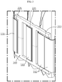
FIG. 1 is a perspective view schematically showing components of a battery module according to an embodiment of the present disclosure. -
FIG. 2 is a plane view schematically showing components of the battery module according to an embodiment of the present disclosure. -
FIG. 3 is an enlarged perspective view showing a portion C of the battery module ofFIG. 1 . -
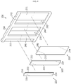
FIG. 4 is an exploded perspective view showing various components of a bus bar employed at the battery module ofFIG. 1 . -
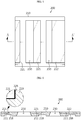
FIG. 5 is a front view showing an example of the bus bar ofFIG. 4 . -
FIG. 6 is a cross-sectioned view showing an example of the cross section, taken along the line A-A' ofFIG. 5 . -
FIG. 7 is a front view schematically showing a bus bar according to another embodiment of the present disclosure. -
FIG. 8 is a cross-sectioned view showing an example of the cross section, taken along the line B-B' ofFIG. 7 . -
FIG. 9 is a rear view showing an example of a rear surface of the bus bar ofFIG. 4 . -
FIG. 10 is a perspective view schematically showing components of a battery module according to another embodiment of the present disclosure. -
FIG. 11 is a plane view schematically showing components of the battery module according to another embodiment of the present disclosure. -
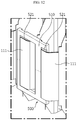
FIG. 12 is an enlarged perspective view showing a portion D of the battery module ofFIG. 10 . -
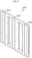
FIG. 13 is an exploded perspective view showing various components of another example of a bus bar employed at the battery module ofFIG. 10 are separated. -
FIG. 14 is a schematic front sectioned view for illustrating an example of a method for manufacturing a bus bar of the battery module according to an embodiment of the present disclosure. - Hereinafter, preferred embodiments of the present disclosure will be described in detail with reference to the accompanying drawings. Prior to the description, it should be understood that the terms used in the specification and the appended claims should not be construed as limited to general and dictionary meanings, but interpreted based on the meanings and concepts corresponding to technical aspects of the present disclosure on the basis of the principle that the inventor is allowed to define terms appropriately for the best explanation.
- Therefore, the description proposed herein is just a preferable example for the purpose of illustrations only, not intended to limit the scope of the disclosure, so it should be understood that other equivalents and modifications could be made thereto without departing from the scope of the disclosure.
-
FIG. 1 is a perspective view schematically showing components of a battery module according to an embodiment of the present disclosure.FIG. 2 is a plane view schematically showing components of the battery module according to an embodiment of the present disclosure.FIG. 3 is an enlarged perspective view showing a portion C of the battery module ofFIG. 1 . - Referring to
FIGS. 1 to 3 , abattery module 300 according to the present disclosure may include a plurality ofsecondary batteries 100 and bus bars 200. - Here, the
secondary battery 100 may be a pouch-typesecondary battery 100. In particular, the pouch-typesecondary battery 100 may include an electrode assembly, an electrolyte and a pouch. - Here, the pouch may be composed of two pouches, namely a left pouch and a right pouch, each having a concave accommodation portion. In addition, each pouch includes an outer insulating layer, a metal layer and an inner adhesive layer, and the inner adhesive layer is fused to each other at an edge of the pouch to form a sealing portion. Also, an electrode assembly and an electrolyte may be accommodated in the accommodation portion.
- In addition, the electrode assembly is an assembly of electrodes and a separator, and may be configured such that at least one positive electrode plate and at least one negative electrode plate are disposed with a separator interposed therebetween. Also, a first electrode plate of the electrode assembly includes a first electrode tab, and at least one first electrode tab may be connected to a
first electrode lead 111. Here, thefirst electrode lead 111 has one end connected to the first electrode tab and the other end exposed out of the pouch, and the exposed portion may serve as an electrode terminal of the secondary battery, for example a positive electrode terminal of thesecondary battery 100. - Also, a second electrode plate of the electrode assembly includes a second electrode tab, and at least one second electrode tab may be connected to a
second electrode lead 112. Thesecond electrode lead 112 has one end connected to the second electrode tab and the other end exposed out of the pouch, and the exposed portion may serve as an electrode terminal of the secondary battery, for example a negative electrode terminal of thesecondary battery 100. - At this time, the first electrode tab and the second electrode tab of the
secondary battery 100 may be a positive electrode tab or a negative electrode tab, and also thefirst electrode lead 111 and thesecond electrode lead 112 may be a positive electrode lead or a negative electrode lead. Further, thefirst electrode lead 111 and thesecond electrode lead 112 may be electrode leads with different polarities. For example, thefirst electrode lead 111 may be a positive electrode lead, and thesecond electrode lead 112 may be a negative electrode lead. - Moreover, the positive electrode lead and negative electrode lead may be provided in opposite directions, based on the center of the
secondary battery 100. For example, as shown inFIGS. 1 and2 , eachsecondary battery 100 may be configured such that thefirst electrode lead 111 and thesecond electrode lead 112 protrude forward and backward. Thus, according to this configuration of the present disclosure, in onesecondary battery 100, there is no interference between the positive electrode lead and the negative electrode lead, thereby widening the area of the electrode lead. In addition, a welding process between the electrode leads and a welding process between the electrode lead and thebus bar 200 may be performed more easily. - Also, the
first electrode lead 111 and thesecond electrode lead 112 may be configured in a plate form. In particular, thefirst electrode lead 111 and thesecond electrode lead 112 may protrude in a horizontal direction in a state of standing so that its broad surfaces are oriented to left and right sides, and then an end thereof may be bent in the left or right direction. In particular, as shown inFIG. 3 , if the electrode leads 112 of thesecondary batteries 100 adjacent to each other have different bent directions, the electrode leads 112 may be configured such that their ends face each other. - A plurality of pouch-type
secondary batteries 100 may be included in thebattery module 300 and arranged to be stacked in at least one direction. For example, as shown inFIGS. 1 and2 , a plurality of pouch-typesecondary batteries 100 may be stacked in a horizontal direction. At this time case, each pouch-typesecondary battery 100 may be disposed to stand approximately perpendicular to the ground, when being observed in the F direction (seeFIG. 1 ), such that two broad surfaces are located at right and left sides, respectively, and the sealing portions are located at upper, lower, front and rear sides. In other words, eachsecondary battery 100 may be configured to stand in an upper and lower direction. Meanwhile, in the specification, the terms indicating directions such as front, rear, left, right, upper and lower directions are based on the F direction, unless stated otherwise. - The configuration of the pouch-type
secondary battery 100 described above is obvious to those skilled in the art and thus is not described in detail. In addition, thebattery module 300 according to the present disclosure may employ various secondary batteries known at the time of filing of this application. - Meanwhile, the
bus bar 200 may be made of an electrically conductive material with relatively high electrical conductivity. Thus, thebus bar 200 configured as above may be in contact with at least two of the first electrode leads 111 and the second electrode leads 112 of thesecondary batteries 100 to electrically connect thesecondary batteries 100. - For example, the
bus bar 200 may be in contact with electrode leads of the same polarity, for example two or more first electrode leads 111, to electrically connect thesecondary batteries 100, or may be in contact with two or more second electrode leads 112 to electrically connect thesecondary batteries 100. Alternatively, thebus bar 200 may be in contact with electrode leads of different polarities, for example one or more first electrode leads 111 and one or more second electrode leads 112, to electrically connect thesecondary batteries 100. - Moreover, the
bus bar 200 may include at least twometal plates secondary batteries 100. More specifically, themetal plates secondary batteries 100. - In particular, among the
metal plates metal plate 221 may be in contact with the first electrode leads 111 of at least twosecondary batteries 100, or themetal plate 222 may be in contact with the second electrode leads 112 of at least twosecondary batteries 100. Thus, according to this configuration of the present application, by using the metal plates, thebus bar 200 may come into contact with at least two electrode leads of the same polarity among the first electrode leads 111 or the second electrode leads 112 of thesecondary batteries 100 to electrically connect thesecondary batteries 100 in parallel. - In addition, the
bus bar 200 may include amain frame 210 coupled to the metal plates such that themetal plates 221 are at least partially exposed to the outside. At this time, the exposed portion of the metal plate may be at least a portion of the front surface and the side surface. In addition, themain frame 210 may be made of an electrically conductive material. - Meanwhile, in a conventional bus bar, when the bus bar is made of a material different from the metal material of the electrode lead, it is inevitable that different kinds of metals are coupled between the electrode lead and the bus bar, and thus the reliability of welding between the bus bar and the electrode lead is deteriorated.
- In order to solve the problems of the prior art, the
bus bar 200 according to an embodiment of the present disclosure includes at least twometal plates 221, and at least one of themetal plates 221 may have a different kind of metal material from themain frame 210. - Here, the metal material may be a single metal material or a metal material formed by a specific combination of different kinds of metals.
- More specifically, any one of the
metal plates 221 may have the same kind of metal material as thebus bar 200, and the other may include a different kind of metal material different from thebus bar 200, or all themetal plates 221 may include a different kind of metal material from thebus bar 200. Thus, according to this configuration of the present disclosure, since thebus bar 200 includes themetal plate 221 having a different kind of metal material from themain frame 210, it is possible to prevent that so that different kinds of metals are coupled when thebus bar 200 is coupled to the electrode lead made of a different kind of metal material from themain frame 210. - Further, the
bus bar 200 according to an embodiment of the present disclosure may include afirst metal plate 221 and asecond metal plate 222. More specifically, thefirst metal plate 221 may be contacted and connected to thefirst electrode lead 111 of at least onesecondary battery 100, and thesecond metal plate 222 may be contacted and connected to thesecond electrode lead 112 of at least onesecondary battery 100. - In particular, the
bus bar 200 may be in contact with electrode leads of thesecondary batteries 100 with different polarities by using thefirst metal plate 221 and thesecond metal plate 222 to electrically connect thesecondary batteries 100 in series. In particular, thefirst metal plate 221 and thesecond metal plate 222 may be in contact with thefirst electrode lead 111 and thesecond electrode lead 112 to electrically connect thesecondary batteries 100 of different polarities in series. Accordingly, thebus bar 200 according to an embodiment of the present disclosure may electrically connect thesecondary batteries 100 in series by means of thefirst metal plate 221 and thesecond metal plate 222. For example, as shown inFIG. 3 , thebus bar 200 may include twofirst metal plates 221 contacted and connected to thefirst electrode lead 111 and onesecond metal plate 222 contacted and connected to thesecond electrode lead 112. - At this time, the
first metal plate 221 and thesecond metal plate 222 may have a plate form. Thus, thefirst metal plate 221 and thesecond metal plate 222 may be in surface contact with the electrode leads having a plate form, and thus the contact area may be widened to effectively reduce the electrical resistance of the contact region. - Further, the
first metal plate 221 and thesecond metal plate 222 may be contacted and connected such that the plurality of first electrode leads 111 or the plurality of second electrode leads 112 partially overlap with each other. More specifically, one surface of one end of thefirst electrode lead 111 may overlap with the other surface of one end of anotherfirst electrode lead 111, and one surface of any one of the first electrode leads 111 may be contacted and connected to thefirst metal plate 221. - Similarly, one surface of one end of the
second electrode lead 112 may overlap with the other surface of one end of anothersecond electrode lead 112, and one surface of any one of the second electrode leads 112 may be contacted and connected to thesecond metal plate 222. - For example, as shown in
FIGS. 2 and3 , thefirst metal plate 221 may be contacted and connected to the first electrode leads 111 in a state where two first electrode leads 111 partially overlap with each other. Also, thesecond metal plate 222 may be contacted and connected to the second electrode leads 112 in a state where two second electrode leads 112 partially overlap with each other. - Also, a portion of the front surface of the
first metal plate 221 and thesecond metal plate 222 may be connected in surface contact to at least one electrode lead. Further, a portion of the front surface and the side surface of thefirst metal plate 221 and thesecond metal plate 222 may be contacted and connected to the electrode lead to increase the contact area with the electrode lead. - In another embodiment, a portion of the front surface of the
first metal plate 221 and thesecond metal plate 222 may be connected in surface contact to two or more electrode leads. More specifically, a portion of the front surface of thefirst metal plate 221 and thesecond metal plate 222 may be connected in surface contact to one electrode lead, and the other region except for the portion surface-contacted to the electrode lead may be connected in surface contact to another electrode lead. - In particular, when the second electrode leads 112 of the adjacent
secondary batteries 100 are bent in different directions, the front surface of thesecond metal plate 222 may be connected in surface contact to the second electrode leads 112 in a state where the ends of the second electrode leads 112 face each other. - For example, as shown in
FIG. 3 , four second electrode leads 112 in total may be connected in surface contact to thesecond metal plate 222 so that their ends face each other, in a state where two second electrode leads 112 overlap with each other, respectively. According to this configuration of the present disclosure, thebus bar 200 including thefirst metal plate 221 and thesecond metal plate 222 may be connected in surface contact to the electrode leads over a large area, and thus it is possible to effectively reduce the electric resistance that may occur in the connection region. -
FIG. 4 is an exploded perspective view showing various components of a bus bar employed at the battery module ofFIG. 1 . - Referring to
FIG. 4 , themain frame 210 may include atop bar 242, abottom bar 244 and aconnection portion 246. - When the
main frame 210 stands in the upper and lower direction, thetop bar 242 may have a bar shape located at an upper portion of themain frame 210 and extending in a horizontal direction. - Also, the
bottom bar 244 may have a bar shape located at a lower portion of themain frame 210 and extending in a horizontal direction. - The
connection portion 246 may be configured to connect thetop bar 242 and thebottom bar 244. More specifically, theconnection portion 246 may have a rib shape extending from thetop bar 242 in a lower direction and connected to thebottom bar 244. Further, at least twoconnection portions 246 may be formed according to the number of thefirst metal plates 221 and thesecond metal plates 222 included in thebus bar 200. - In addition, the
first metal plate 221 may be made of the same material as thefirst electrode lead 111 of thesecondary battery 100, which is contacted and connected thereto. In addition, thesecond metal plate 222 may be made of the same material as thesecond electrode lead 112 of thesecondary battery 100, which is contacted and connected thereto. Here, the material of thefirst electrode lead 111 and thesecond electrode lead 112 may be a metal with excellent electrical conductivity, generally the metal used for the electrode lead of thesecondary battery 100. - Thus, in the
bus bar 200 according to an embodiment of the present disclosure, thefirst metal plate 221 and thesecond metal plate 222 are made of the same material as the electrode leads contacted and connected thereto, and so it is possible to avoid that different kinds of metals are coupled when thebus bar 200 and the electrode lead are welded, thereby improving the bonding strength and bonding reliability between the bus bar and the electrode lead. - Meanwhile, the
first metal plate 221, thesecond metal plate 222 and themain frame 210 are components included in thebus bar 200 and may include a metal material to have electrical conductivity. - Specifically, the
first metal plate 221 may be made of at least one electrically conductive material selected from the group consisting of, for example, nickel, copper, aluminum, lead and tin. For example, thefirst metal plate 221 may be an aluminum material. However, the present disclosure is not necessarily limited thereto, and various metals may also be used as the material of thefirst metal plate 221. - In addition, the
second metal plate 222 may also be made of at least one electrically conductive material selected from the group consisting of, for example, nickel, copper, aluminum, lead and tin. For example, thesecond metal plate 222 may be a copper material. However, the present disclosure is not necessarily limited thereto, and various metals may also be used as the material of thesecond metal plate 222. - Generally, since the positive electrode lead and the negative electrode lead of the secondary battery are set to be made of different kinds of materials, preferably, the
bus bar 200 of the present disclosure may include afirst metal plate 221 and asecond metal plate 222 made of different kinds of material. For example, if thefirst metal plate 221 is made of an aluminum material, thesecond metal plate 222 may be made of a copper material. - Also, the
main frame 210 may be made of at least one electrically conductive material selected from the group consisting of nickel, copper, aluminum, lead and tin. For example, themain frame 210 may be a copper material. However, the present disclosure is not necessarily limited to this, and various metals may also be used as the material of themain frame 210. - Further, the
main frame 210 may be made of the same material as any one of thefirst metal plate 221 and thesecond metal plate 222, and may be made of a material different from the other thereof. For example, themain frame 210 may be made of a copper material like thesecond metal plate 222, and thefirst metal plate 221 may be made of an aluminum material. -
FIG. 5 is a front view showing an example of the bus bar ofFIG. 4 . In addition,FIG. 6 is a cross-sectioned view showing an example of the cross section, taken along the line A-A' ofFIG. 5 . - Referring to
FIGS. 5 and 6 along withFIG. 4 , themain frame 210 may have a placingportion 211 for mounting thefirst metal plate 221 or thesecond metal plate 222 on the front surface thereof. For example, the placingportion 211 may be formed in themain frame 210 with a recessed structure in a size corresponding to thefirst metal plate 221 or thesecond metal plate 222 so as to be closely adhered to the outer surface of thefirst metal plate 221 or thesecond metal plate 222. - Thus, according to this configuration of the present disclosure, the
first metal plate 221 and thesecond metal plate 222 of thebus bar 200 may be stably mounted on the placingportion 211 of themain frame 210, and thus it is possible to facilitate the contact connection work between the electrode lead and the metal plate. In addition, according to this configuration, thefirst metal plate 221 and thesecond metal plate 222 are not easily deviated from thebus bar 200 due to an external impact, and thus it is possible to improve the durability of thebus bar 200. - More specifically, the placing
portion 211 may be in contact with at least a portion of the rear surface of thefirst metal plate 221 and thesecond metal plate 222. For example, as shown inFIG. 6 , the placingportion 211 may be in contact with the entire rear surface of thefirst metal plate 221 or thesecond metal plate 222 to maximize the bonding area between themain frame 210 and themetal plates - Also, the placing
portion 211 may be in contact with at least a portion of the side surfaces of thefirst metal plate 221 and thesecond metal plate 222. Moreover, the placingportion 211 may be in contact with the entire side surfaces of thefirst metal plate 221 and thesecond metal plate 222. - For example, as shown in
FIG. 4 , the placingportion 211 may be in contact with asecond side surface 232, athird side surface 233 and afourth side surface 234 of thefirst metal plate 221. In addition, the placingportion 211 may be in contact with asecond side surface 242 and afourth side surface 244 of thesecond metal plate 222. -
FIG. 7 is a front view schematically showing a bus bar according to another embodiment of the present disclosure. In addition,FIG. 8 is a cross-sectioned view showing an example of the cross section, taken along the line B-B' ofFIG. 7 . However, inFIG. 7 , a portion of the metal plate buried in the main frame is depicted with dotted lines for convenience of explanation. - Referring to
FIGS. 7 and 8 , in thebus bar 400 according to another embodiment of the present disclosure, the placingportion 411 may be configured to be in contact with a portion of the front surface of thefirst metal plate 221 and thesecond metal plate 222. - At this time, if the placing
plate 411 for mounting thefirst metal plate 221 or thesecond metal plate 222 is in contact with the entire front surface of thefirst metal plate 221 or thesecond metal plate 222, the electrode lead contacted and connected to the front surface of thefirst metal plate 221 or thesecond metal plate 222 is not easily contacted or connected to the metal plate, and thus it is preferable that the placingportion 411 is formed to be in contact with a portion of the front surface of thefirst metal plate 221 and thesecond metal plate 222. For example, the placingportion 411 may be formed to be in contact with 10% to 50% of the entire front surface of thefirst metal plate 221 and thesecond metal plate 222. - In particular, if the
first metal plate 221 and thesecond metal plate 222 are formed in a plate form standing vertically, thefirst metal plate 221 and/or thesecond metal plate 222 may be configured to be inserted into the placingportion 411 so that at least one of atop end 251, abottom end 252 and side ends 253 thereof is covered. - For example, as shown in
FIGS. 7 and 8 , the placingportion 411 may be formed to cover thefront surface 226, therear surface 227 and theside surface 228 of thetop end 251, thebottom end 252 and theside end 253 of thefirst metal plate 221. Also, the placingportion 411 may be formed to cover the front surface, the rear surface and the side surface of thetop end 262 and thebottom end 264 of thesecond metal plate 222. Thebus bar 400 according to this configuration is configured such that a portion of themain frame 410 covers the front surface, the rear surface and the side surface of thefirst metal plate 221 or thesecond metal plate 222, thereby effectively preventing the metal plate from being separated from the bus bar due to an external impact or the like. - However, when the
first metal plate 221 and thesecond metal plate 222 are mounted to themain frame 210, the present disclosure is not limited to the above manner, and thefirst metal plate 221 and thesecond metal plate 222 may be mounted to themain frame 210 in various forms. - In addition, the front surface of the
first metal plate 221 or thesecond metal plate 222 exposed to the outside is not protruded forward further, based on the front surface of themain frame 410 exposed to the outside, but may be positioned on the same plane or to be recessed rearward. - For example, as shown in
FIG. 8 , the front surface of thefirst metal plate 221 exposed to the outside is recessed rearward, based on the front surface of themain frame 410 exposed to the outside. - Thus, according to this configuration of the present disclosure, the
bus bar 400 prevents the outwardly protruding metal plate from interfering with an external object, and thus it is possible to prevent the metal plate from improperly contacting an external object and being damaged. Also, it is possible to reduce the space occupied by thebus bar 400 in thebattery module 300 by reducing the thickness of thebus bar 400 in the front and rear direction. - Moreover, the
bus bar 400 may be configured such that the electrode leads 111, 112 may be located parallel to the front surface of themain frame 410 exposed to the outside or be recessed rearward even though the electrode leads 111, 112 are contacted and connected to the exposed front surfaces of thefirst metal plate 221 and thesecond metal plate 222. - According to this configuration of the present disclosure, it is possible to prevent the
first electrode lead 111 or thesecond electrode lead 112 coupled to thebus bar 400 from interfering with an external object. Thus, in this case, it is possible to easily assemble thebattery module 300, to prevent the electrode leads 111, 112 from improperly contacting an external conductive object, and also to prevent the electrode lead from being damaged due to the collision with an external object. - Referring to
FIGS. 5 and 6 again, thefirst metal plate 221 and thesecond metal plate 222 may be formed by plastic working using a press. The plastic working by a press may be performed in a way that the outer shape of the metal plate is formed by slowly pressing a target by using a forging press. This method is advantageous in that there is no noise or vibration and no pore is formed in the metal. Thus, according to this configuration of the present disclosure, thefirst metal plate 221 and thesecond metal plate 222 may be formed thinly and tightly. In particular, in this case, since no pore is formed in the metal plate, it is possible to prevent the metal plate from being damaged during a work such as laser welding in which a high temperature is applied. - Also, the
main frame 210 may be configured such that the placingportion 211 and thefirst metal plate 221 or thesecond metal plate 222 are closely adhered to each other by casting. Here, the casting may be, for example, die casting, and the die casting may be a method of melting a metal material by heating and then injecting the metal material into a mold with a desired shape to make a product. If themain frame 210 is made by the casting, a complicated structure may be precisely formed without performing additional finishing operations, and a process for reducing the weight of parts such as slimming may be easily performed. In particular, if an explosive casting method is used, a high-qualitymain frame 210 having reduced pores in the metal may be formed. However, when the main frame of the present disclosure is made by casting, the present disclosure is not limited to these specific casting methods. - In addition, as shown in
FIG. 6 , aportion 225 where the placingportion 211 of themain frame 210 and thefirst metal plate 221 are in direct contact with each other may be configured such that a partial metal of thefirst metal plate 221 and a partial metal of themain frame 210 are melted in mixture and bonded to each other. - The melted and bonded
portion 225 may be formed as themain frame 210 in a high temperature state comes into contact with thefirst metal plate 221 when themain frame 210 is cast in a state where thefirst metal plate 221 is interposed. That is, at the bondedportion 225 of thefirst metal plate 221 and themain frame 210, a partial metal of thefirst metal plate 221 and a partial metal of themain frame 210 are mixed with each other, and then the mixed portion becomes solidified to bond thefirst metal plate 221 and themain frame 210. - Thus, according to this configuration of the present disclosure, the
first metal plate 221 and themain frame 210 may be reliably coupled to each other with a high bonding force by compensating for the deterioration of bonding force generated when the metal materials of thefirst metal plate 221 and themain frame 210 are different from each other. - In particular, the
portion 225 of thefirst metal plate 221, closely adhered to the placingportion 211, may be instantly heated and melted while being in contact with the thermally melted metal material of themain frame 210 during the casting process, and then be bonded to themain frame 210. Alternatively, the portion of thefirst metal plate 221 closely adhered to the placingportion 211 may be instantly heated and melted using a heater and then bonded to themain frame 210. However, the present disclosure is not necessarily limited to the above heating method, and various heating methods may be used for melting and bonding. - Further, similar to the
first metal plate 221 described above, the portion of thesecond metal plate 222 closely adhered to the placingportion 211 of themain frame 210 may also be melted and bonded to themain frame 210 in a state where the metal of thesecond metal plate 222 and the metal of themain frame 210 are mixed with each other. - Thus, according to this configuration of the present disclosure, the deterioration of the bonding force caused when the
second metal plate 222 and themain frame 210 have different metal materials is compensated, and thus thesecond metal plate 222 and themain frame 210 may be reliably coupled with a high bonding force. - Also, the
main frame 210 formed by casting may have at least one hole formed in the placingportion 211. In addition, thefirst metal plate 221 and thesecond metal plate 222 may have at least one protrusion having a shape corresponding to the hole. In particular, the hole of themain frame 210 may be coupled in a state where the protrusion of thefirst metal plate 221 or thesecond metal plate 222 is inserted therein through the casting process. - Thus, according to this configuration of the present disclosure, the coupling structure of the protrusion and the hole may more firmly fix the coupling state of the
main frame 210 and thefirst metal plate 221 or thesecond metal plate 222. - Further, the coupling structure of the protrusion and the hole may prevent the
first metal plate 221 and thesecond metal plate 222 from moving when thefirst metal plate 221 and thesecond metal plate 222 are welded and coupled to the electrode leads or when thebattery module 300 is being moved or used. - Referring to
FIGS. 5 and 6 again, themain frame 210 may have at least onehole 230 formed therein. Further, thehole 230 may be formed to penetrate themain frame 210 in the front and rear direction. More specifically, thehole 230 may be formed in a shape corresponding to an end surface in the direction in which thefirst electrode lead 111 or thesecond electrode lead 112 protrudes. Thus, according to this configuration of the present disclosure, thefirst electrode lead 111 or thesecond electrode lead 112 may be easily inserted through thehole 230 without interference, thereby improving manufacturing efficiency. - Also, the
hole 230 may be formed to be in contact with one side of thefirst metal plate 221 or thesecond metal plate 222 or at least in proximity with one side of thefirst metal plate 221 or thesecond metal plate 222. - For example, as shown in
FIG. 5 , thehole 230 may be formed in contact with one side of thefirst metal plate 221 or thesecond metal plate 222. In this case, thehole 230 may be configured such that one side surface of thefirst metal plate 221 or thesecond metal plate 222 is exposed to thehole 230. In this case, the extension length for thefirst electrode lead 111 or thesecond electrode lead 112 to contact thefirst metal plate 221 and thesecond metal plate 222 may be further minimized, and it is advantageous to for preventing the electrode lead from being broken or disconnected due to an external impact. -
FIG. 9 is a rear view showing an example of a rear surface of the bus bar ofFIG. 4 . - Referring to
FIGS. 4 and9 , themain frame 210 may be configured to have at least one recessedportion 218 formed at the rear surface thereof. Specifically, the recessedportion 218 may be shaped to avoid interference with other components of thebattery module 300, and, for example, the recessedportion 218 may be formed with a stepped structure where a partial surface of themain frame 210 is recessed forwardly. - Also, the recessed
portion 218 may be formed to extend from the top end to the bottom end. For example, as shown inFIG. 9 , three recessedportions 218 may be formed at the rear surface of themain frame 210 to be recessed to the front of themain frame 210. For example, thebus bar 200 may avoid interference with components protruding to the front of thesecondary battery 100 of thebattery module 300, by forming the recessedportion 218. - Thus, according to this configuration of the present disclosure, by forming the recessed
portion 218 at thebus bar 200, it is possible to reduce the weight of thebattery module 300 and reduce an unnecessary volume of the internal structure, thereby enabling to manufacture a morecompact battery module 300. -
FIG. 10 is a perspective view schematically showing components of a battery module according to another embodiment of the present disclosure. In addition,FIG. 11 is a plane view schematically showing components of the battery module according to another embodiment of the present disclosure. Here, the features similar or identical to those of the former embodiment will not be described in detail, and features different from the former embodiment will be described in detail. - Referring to
FIGS. 10 and11 , abattery module 600 according to another embodiment of the present disclosure may include abus bar 500 having a different shape from thebus bar 200 included in thebattery module 300 ofFIG. 1 . - In detail, the
battery module 600 may include another type ofbus bar 500 that contacts the first electrode leads 111 or the second electrode leads 112 to electrically connect thesecondary batteries 100 in parallel. - In addition, the
battery module 600 may include both of thebus bar 200 that contacts both the first electrode leads 111 and the second electrode leads 112 of thesecondary batteries 100 to electrically connect thesecondary batteries 100 in series and another type ofbus bar 500 that contacts the first electrode leads 111 or the second electrode leads 112 to electrically connect thesecondary batteries 100 in parallel. - For example, as shown in
FIGS. 10 and11 , when thefirst electrode lead 111 and thesecond electrode lead 112 of thesecondary battery 100 are respectively protruded forward and backward, twobus bars 200 and two another type ofbus bars 500 may be formed at the front and rear sides of thebattery module 600. -
FIG. 12 is an enlarged perspective view showing a portion D of the battery module ofFIG. 10 . In addition,FIG. 13 is an exploded perspective view showing various components of another example of a bus bar employed at the battery module ofFIG. 10 are separated. - Also, the
bus bar 500 may include amain frame 510 and at least twometal plates 521. - More specifically, the
bus bar 500 may include at least onethird metal plate 521 contacted and connected to the first electrode leads 111 or the second electrode leads 112 of at least twosecondary batteries 100. For example, as shown inFIG. 12 , thebus bar 500 includes twothird metal plates 521 contacted and connected to the first electrode leads 111 of twosecondary batteries 100. - In particular, the
third metal plate 521 may include a different kind of metal material from themain frame 510. Accordingly, according to this configuration of the present disclosure, since thebus bar 500 includes a metal plate having a different kind of metal material from themain frame 510, it is possible to prevent that different kinds of metals are bonded when thebus bar 500 is coupled to the electrode lead made of a different kind of metal material from themain frame 510. - For example, as shown in
FIG. 12 , thebus bar 500 may include twothird metal plates 521, and each of thethird metal plates 521 may be contacted and connected to two first electrode leads 111 that partially overlap with each other. Thus, according to this configuration of the present invention, thebus bar 500 may electrically connect foursecondary batteries 100 in parallel. - In addition, as shown in
FIG. 13 , themain frame 510 may have placingportions 511 formed at a front surface thereof. Further, the placingportion 511 may be configured such that thethird metal plate 521 is placed thereon. - For example, the placing
portion 511 may be formed to be recessed with a size corresponding to thethird metal plate 521. In this case, thethird metal plate 521 may be stably coupled to themain frame 510 without being easily deviated due to an external impact. - Also, the
main frame 510 may have at least one hole. For example, as shown inFIG. 13 , one hole may be formed at one side of the placingportion 511. -
FIG. 14 is a schematic front sectioned view for illustrating an example of a method for manufacturing a bus bar of the battery module according to an embodiment of the present disclosure. - Referring to
FIG. 14 along withFIG. 4 , a method for manufacturing thebus bar 200 according to the present disclosure includes the following steps. - First, in a process (a), a
first metal plate 221 and asecond metal plate 222 shaped by plastic working using a press may be prepared. - In addition, in a process (b), the prepared
first metal plate 221 and the preparedsecond metal plate 222 may be mounted and fixed in amold 400. - Also, in a process (c), a
molten metal 215 may be injected into aninjection hole 410 formed in themold 400 so as to be coupled to at least a portion of thefirst metal plate 221 and thesecond metal plate 222, and then, the injectedmolten metal 215 is cooled and solidified to cast themain frame 210. - At this time, the heat of the injected
molten metal 215 may come into contact with a portion of thefirst metal plate 221 and thesecond metal plate 222 mounted in themold 400 so that the heat is conducted to the contacted outer surface of thefirst metal plate 221 and thesecond metal plate 222. - In this case, the portions of the
first metal plate 221 and thesecond metal plate 222, which are in contact with the injectedmolten metal 215, may be melted and bonded in a state where a part of the metal is melted by the conducted heat and mixed with the injectedmolten metal 215. Thus, according to this configuration of the present disclosure, thefirst metal plate 221 and thesecond metal plate 222 may be coupled to themain frame 210 with a strong coupling force. - Finally, in a process (d), the
main frame 210 solidified in a state of being coupled to thefirst metal plate 221 and thesecond metal plate 222 is taken out of themold 400, thereby completely manufacturing thebus bar 200. - In addition, a battery pack according to the present disclosure may include one or more battery modules according to the present disclosure. Further, the battery pack according to the present disclosure may further include, in addition to the battery module, a pack case for accommodating the
battery module 400, various devices for controlling charge and discharge of thebattery module 400 such as a battery management system (BMS), a current sensor, a fuse and the like. - In addition, the battery pack according to the present disclosure may be applied to a vehicle such as an electric vehicle or a hybrid electric vehicle. In other words, the vehicle according to the present disclosure may include the battery pack of the present disclosure.
- Meanwhile, even though the terms indicating directions such as upper, lower, left, right, front and rear directions are used in the specification, it is obvious to those skilled in the art that these merely represent relative locations for convenience in explanation and may vary based on a location of an observer or an object.
- The present disclosure has been described in detail. However, it should be understood that the detailed description and specific examples, while indicating preferred embodiments of the disclosure, are given by way of illustration only, since various changes and modifications within the scope of the disclosure will become apparent to those skilled in the art from this detailed description.
- The present disclosure relates to a battery module, in particular, the present disclosure may be applied to industries associated with a battery pack configured using the battery modules and a vehicle driven by the battery pack, for example an electrical vehicle.
Claims (17)
- A battery module, comprising:a plurality of pouch-type secondary batteries configured to respectively have a first electrode lead and a second electrode lead and arranged to be stacked in at least one direction; anda bus bar made of an electrically conductive material and contacted to at least two of the first and second electrode leads of the secondary batteries to electrically connect the secondary batteries to each other,wherein the bus bar includes:at least two metal plates contacted and connected to at least two of the first electrode leads and the second electrode leads of at least two secondary batteries; anda main frame coupled to the metal plates so that the metal plates are at least partially exposed to the outside,wherein at least one of the metal plates has a different kind of metal material from the main frame.
- The battery module according to claim 1,
wherein the metal plates include:a first metal plate contacted and connected to the first electrode lead of at least one secondary battery; anda second metal plate contacted and connected to the second electrode lead of at least one secondary battery. - The battery module according to claim 2,
wherein the first metal plate is made of the same material as the first electrode lead of the secondary battery to which the first metal plate is contacted and connected, and
wherein the second metal plate is made of the same material as the second electrode lead of the secondary battery to which the second metal plate is contacted and connected. - The battery module according to claim 3,
wherein the first metal plate, the second metal plate or the main frame includes nickel, copper, aluminum, lead or tin. - The battery module according to claim 3,
wherein a placing portion recessed with a size corresponding to the first metal plate or the second metal plate is formed at a front surface of the main frame. - The battery module according to claim 5,
wherein an outwardly exposed front surface of the first metal plate or the second metal plate is recessed to the rear, based on the front surface of the main frame, which is exposed to the outside. - The battery module according to claim 5,
wherein a portion of the front surface, a rear surface and at least a portion of a side surface of the first metal plate and the second metal plate are in contact with the placing portion of the main frame. - The battery module according to claim 5,
wherein the first metal plate and the second metal plate have a plate form standing in an upper and lower direction, and
wherein the first metal plate and the second metal plate are inserted into the placing portion to cover a front surface, a rear surface and a side surface of at least one of a top end, a bottom end and a side end of the first metal plate and the second metal plate, respectively. - The battery module according to claim 5,
wherein the first metal plate and the second metal plate are shaped by means of plastic working, and
wherein the main frame is formed by casting so that the placing portion, the first metal plate and the second metal plate are closely adhered to each other. - The battery module according to claim 9,
wherein a portion of the first metal plate closely adhered to the placing portion of the main frame is melted and bonded to the main frame in a state where the metal of the first metal plate and the metal of the main frame are mixed, and
wherein a portion of the second metal plate closely adhered to the placing portion of the main frame is melted and bonded to the main frame in a state where the metal of the second metal plate and the metal of the main frame are mixed. - The battery module according to claim 1,
wherein the main frame has a plurality of holes formed therein so that the first electrode lead and the second electrode lead are respectively inserted therethrough. - The battery module according to claim 11,
wherein the holes are formed in contact with one side of the first metal plate and the second metal plate, respectively. - The battery module according to claim 1,
wherein at least one recessed portion recessed to the front of the main frame is formed at a rear surface of the main frame. - A method for manufacturing a bus bar, comprising:(a) preparing a first metal plate and a second metal plate shaped by plastic working using a press;(b) mounting and fixing the first metal plate and the second metal plate in a mold; and(c) injecting a molten metal into the mold so as to be coupled to at least a portion of the first metal plate and the second metal plate and solidifying the molten metal to cast a main frame,wherein at least one of the first metal plate and the second metal plate has a different kind of metal material from the main frame.
- A battery pack, comprising a battery module according to any one of claims 1 to 13.
- A vehicle, comprising a battery pack according to claim 15.
- A bus bar, which is in contact with at least two of first electrode leads and second electrode leads of secondary batteries to electrically connect the secondary batteries, the bus bar comprising:at least two metal plates contacted and connected to at least two of the first electrode leads and the second electrode leads of at least one secondary battery; anda main frame coupled to the metal plate so that the metal plate is at least partially exposed to the outside,wherein at least one of the metal plates has a different kind of metal material from the main frame.
Applications Claiming Priority (2)
| Application Number | Priority Date | Filing Date | Title |
|---|---|---|---|
| KR1020170066191A KR102209773B1 (en) | 2017-05-29 | 2017-05-29 | Battery Module |
| PCT/KR2018/000283 WO2018221818A1 (en) | 2017-05-29 | 2018-01-05 | Battery module |
Publications (3)
| Publication Number | Publication Date |
|---|---|
| EP3547401A1 true EP3547401A1 (en) | 2019-10-02 |
| EP3547401A4 EP3547401A4 (en) | 2020-02-19 |
| EP3547401B1 EP3547401B1 (en) | 2023-07-26 |
Family
ID=64455851
Family Applications (1)
| Application Number | Title | Priority Date | Filing Date |
|---|---|---|---|
| EP18809421.3A Active EP3547401B1 (en) | 2017-05-29 | 2018-01-05 | Battery module |
Country Status (6)
| Country | Link |
|---|---|
| US (1) | US11342631B2 (en) |
| EP (1) | EP3547401B1 (en) |
| JP (1) | JP7045576B2 (en) |
| KR (1) | KR102209773B1 (en) |
| CN (1) | CN110100330B (en) |
| WO (1) | WO2018221818A1 (en) |
Cited By (1)
| Publication number | Priority date | Publication date | Assignee | Title |
|---|---|---|---|---|
| EP4187704A4 (en) * | 2021-02-10 | 2024-03-27 | Lg Energy Solution Ltd | Battery module, battery pack, and vehicle |
Families Citing this family (5)
| Publication number | Priority date | Publication date | Assignee | Title |
|---|---|---|---|---|
| CN110621314A (en) * | 2017-01-04 | 2019-12-27 | 艾克萨姆治疗公司 | Pharmaceutical composition comprising meloxicam |
| KR102379227B1 (en) * | 2018-12-26 | 2022-03-24 | 주식회사 엘지에너지솔루션 | Battery module, battery pack comprising the battery module and vehicle comprising the battery pack |
| KR20210015364A (en) * | 2019-08-02 | 2021-02-10 | 주식회사 엘지화학 | Bus bar having surface uneven structures and battery module comprising thereof |
| KR20220011529A (en) * | 2020-07-21 | 2022-01-28 | 주식회사 엘지에너지솔루션 | Battery module with improved electrode lead connection structure, and battery pack and vehicle comprising the same |
| US20220069422A1 (en) * | 2020-08-31 | 2022-03-03 | Apple Inc. | Cast-in-place busbars for battery pack |
Family Cites Families (27)
| Publication number | Priority date | Publication date | Assignee | Title |
|---|---|---|---|---|
| JP2008137059A (en) | 2006-11-29 | 2008-06-19 | Shigeo Hirose | Metallic structure |
| DE102010013351A1 (en) * | 2010-03-30 | 2011-12-15 | Li-Tec Battery Gmbh | Contact element for arresters of galvanic cells |
| KR20120081821A (en) * | 2011-01-12 | 2012-07-20 | (주)브이이엔에스 | A battery module |
| CN103098261B (en) | 2011-01-27 | 2014-04-02 | 株式会社新王材料 | Connection plate for cell terminal and method for manufacturing connection plate for cell terminal |
| KR101244739B1 (en) * | 2011-05-09 | 2013-03-18 | 로베르트 보쉬 게엠베하 | Battery module |
| WO2013051012A2 (en) * | 2011-06-06 | 2013-04-11 | Tata Motors Limited | Bimetallic busbar device for battery cell assemblies |
| DE102011109238A1 (en) | 2011-08-02 | 2013-02-07 | Daimler Ag | Battery with multiple battery cells and method of making same |
| KR101148183B1 (en) | 2011-09-07 | 2012-05-29 | (주)대신제일 | Mold and method of bus bar |
| KR20130049984A (en) * | 2011-11-07 | 2013-05-15 | 아이피지 포토닉스 코리아(주) | Bus bar for battery and battery module |
| CN103460447B (en) * | 2011-11-28 | 2016-06-15 | 株式会社Lg化学 | Battery module and the busbar being applied to battery module |
| US9318734B2 (en) | 2012-05-21 | 2016-04-19 | Tyco Electronics Corporation | Bimetal buss bar assembly |
| JP2014022195A (en) * | 2012-07-18 | 2014-02-03 | Toshiba Corp | Battery pack |
| JP5854061B2 (en) * | 2014-01-31 | 2016-02-09 | 日産自動車株式会社 | Assembled battery |
| KR101637638B1 (en) | 2014-02-18 | 2016-07-07 | 현대자동차주식회사 | Casting product and manufacturing method thereof |
| KR102117371B1 (en) | 2014-03-24 | 2020-06-01 | 에스케이이노베이션 주식회사 | Busbar |
| US10396334B2 (en) | 2014-03-31 | 2019-08-27 | Lg Chem, Ltd. | Battery module and battery pack comprising same |
| KR101736377B1 (en) * | 2014-06-09 | 2017-05-16 | 주식회사 엘지화학 | Battery module and battery pack including the same |
| KR101834506B1 (en) * | 2015-03-27 | 2018-03-05 | 주식회사 엘지화학 | Cell Module |
| KR102416528B1 (en) | 2015-04-06 | 2022-07-01 | 삼성에스디아이 주식회사 | Rechargeable battery |
| KR102002953B1 (en) | 2015-05-26 | 2019-07-23 | 주식회사 엘지화학 | Method and apparatus for manufacturing electrode lead |
| US10453582B2 (en) | 2015-09-09 | 2019-10-22 | Mitsubishi Materials Corporation | Copper alloy for electronic/electrical device, copper alloy plastically-worked material for electronic/electrical device, component for electronic/electrical device, terminal, and busbar |
| JP5910790B1 (en) | 2015-12-01 | 2016-04-27 | 三菱マテリアル株式会社 | Copper alloy for electronic and electric equipment, copper alloy plastic working material for electronic and electric equipment, parts for electronic and electric equipment, terminals, and bus bars |
| CN108140790B (en) * | 2015-10-22 | 2019-04-09 | 日产自动车株式会社 | Group battery and the manufacturing method for organizing battery |
| KR102047482B1 (en) * | 2015-10-30 | 2019-12-02 | 주식회사 엘지화학 | Battery module and battery pack including the same |
| KR102047480B1 (en) | 2015-10-30 | 2019-11-21 | 주식회사 엘지화학 | Battery module and battery pack including the same |
| KR20170056877A (en) | 2015-11-16 | 2017-05-24 | 한국단자공업 주식회사 | Fuse unit mounted on battery |
| KR20170066191A (en) | 2016-04-15 | 2017-06-14 | 이해랑 | A multistage cultivator for vegetable garden |
-
2017
- 2017-05-29 KR KR1020170066191A patent/KR102209773B1/en active IP Right Grant
-
2018
- 2018-01-05 CN CN201880005196.XA patent/CN110100330B/en active Active
- 2018-01-05 EP EP18809421.3A patent/EP3547401B1/en active Active
- 2018-01-05 WO PCT/KR2018/000283 patent/WO2018221818A1/en unknown
- 2018-01-05 JP JP2019558320A patent/JP7045576B2/en active Active
- 2018-01-05 US US16/465,871 patent/US11342631B2/en active Active
Cited By (1)
| Publication number | Priority date | Publication date | Assignee | Title |
|---|---|---|---|---|
| EP4187704A4 (en) * | 2021-02-10 | 2024-03-27 | Lg Energy Solution Ltd | Battery module, battery pack, and vehicle |
Also Published As
| Publication number | Publication date |
|---|---|
| EP3547401B1 (en) | 2023-07-26 |
| JP7045576B2 (en) | 2022-04-01 |
| US20190305284A1 (en) | 2019-10-03 |
| KR102209773B1 (en) | 2021-01-28 |
| WO2018221818A1 (en) | 2018-12-06 |
| KR20180130281A (en) | 2018-12-07 |
| US11342631B2 (en) | 2022-05-24 |
| EP3547401A4 (en) | 2020-02-19 |
| CN110100330B (en) | 2022-07-19 |
| CN110100330A (en) | 2019-08-06 |
| JP2020503660A (en) | 2020-01-30 |
Similar Documents
| Publication | Publication Date | Title |
|---|---|---|
| US11342631B2 (en) | Battery module having a bus bar with a main frame and metal plates | |
| CN110915025B (en) | Bus bar, battery module including the same, and battery pack including the battery module | |
| CN111247662B (en) | Battery module, battery pack and device | |
| CN110892552B (en) | Battery module, battery pack including the same, and vehicle including the battery pack | |
| CN110832692B (en) | Battery module including sensing assembly and bus bar assembly | |
| CN110447125B (en) | Battery module provided with end frames | |
| EP3561906B1 (en) | Battery module | |
| KR102177694B1 (en) | Battery Module Having Bus Bar Assembly | |
| CN110692149A (en) | Battery module with bus bar assembly | |
| CN111418090B (en) | Battery module, battery pack, apparatus, and method of manufacturing module bus bar | |
| EP4053990A1 (en) | Battery module comprising module bus bar, battery pack comprising same, and electronic device | |
| US11302977B2 (en) | Secondary battery pack having connection slot | |
| JP2023501735A (en) | Battery packs, electronic devices and automobiles containing them | |
| EP3792992B1 (en) | Battery module comprising module housing | |
| US11984612B2 (en) | Battery module comprising module housing |
Legal Events
| Date | Code | Title | Description |
|---|---|---|---|
| STAA | Information on the status of an ep patent application or granted ep patent |
Free format text: STATUS: THE INTERNATIONAL PUBLICATION HAS BEEN MADE |
|
| PUAI | Public reference made under article 153(3) epc to a published international application that has entered the european phase |
Free format text: ORIGINAL CODE: 0009012 |
|
| STAA | Information on the status of an ep patent application or granted ep patent |
Free format text: STATUS: REQUEST FOR EXAMINATION WAS MADE |
|
| 17P | Request for examination filed |
Effective date: 20190628 |
|
| AK | Designated contracting states |
Kind code of ref document: A1 Designated state(s): AL AT BE BG CH CY CZ DE DK EE ES FI FR GB GR HR HU IE IS IT LI LT LU LV MC MK MT NL NO PL PT RO RS SE SI SK SM TR |
|
| AX | Request for extension of the european patent |
Extension state: BA ME |
|
| A4 | Supplementary search report drawn up and despatched |
Effective date: 20200117 |
|
| RIC1 | Information provided on ipc code assigned before grant |
Ipc: H01M 2/10 20060101ALI20200113BHEP Ipc: H01M 2/20 20060101AFI20200113BHEP Ipc: H01M 2/02 20060101ALI20200113BHEP Ipc: H01M 2/26 20060101ALI20200113BHEP |
|
| DAV | Request for validation of the european patent (deleted) | ||
| DAX | Request for extension of the european patent (deleted) | ||
| RAP1 | Party data changed (applicant data changed or rights of an application transferred) |
Owner name: LG ENERGY SOLUTION LTD. |
|
| RAP3 | Party data changed (applicant data changed or rights of an application transferred) |
Owner name: LG ENERGY SOLUTION, LTD. |
|
| REG | Reference to a national code |
Ref country code: DE Ref legal event code: R079 Ref document number: 602018054163 Country of ref document: DE Free format text: PREVIOUS MAIN CLASS: H01M0002200000 Ipc: H01M0050105000 Ref legal event code: R079 Ipc: H01M0050105000 |
|
| RIC1 | Information provided on ipc code assigned before grant |
Ipc: H01M 50/522 20210101ALI20230118BHEP Ipc: H01M 50/507 20210101ALI20230118BHEP Ipc: H01M 50/503 20210101ALI20230118BHEP Ipc: H01M 50/50 20210101ALI20230118BHEP Ipc: H01M 50/211 20210101ALI20230118BHEP Ipc: H01M 50/124 20210101ALI20230118BHEP Ipc: H01M 50/119 20210101ALI20230118BHEP Ipc: H01M 50/105 20210101AFI20230118BHEP |
|
| GRAP | Despatch of communication of intention to grant a patent |
Free format text: ORIGINAL CODE: EPIDOSNIGR1 |
|
| STAA | Information on the status of an ep patent application or granted ep patent |
Free format text: STATUS: GRANT OF PATENT IS INTENDED |
|
| INTG | Intention to grant announced |
Effective date: 20230224 |
|
| GRAS | Grant fee paid |
Free format text: ORIGINAL CODE: EPIDOSNIGR3 |
|
| GRAA | (expected) grant |
Free format text: ORIGINAL CODE: 0009210 |
|
| STAA | Information on the status of an ep patent application or granted ep patent |
Free format text: STATUS: THE PATENT HAS BEEN GRANTED |
|
| P01 | Opt-out of the competence of the unified patent court (upc) registered |
Effective date: 20230530 |
|
| AK | Designated contracting states |
Kind code of ref document: B1 Designated state(s): AL AT BE BG CH CY CZ DE DK EE ES FI FR GB GR HR HU IE IS IT LI LT LU LV MC MK MT NL NO PL PT RO RS SE SI SK SM TR |
|
| REG | Reference to a national code |
Ref country code: CH Ref legal event code: EP |
|
| REG | Reference to a national code |
Ref country code: DE Ref legal event code: R096 Ref document number: 602018054163 Country of ref document: DE |
|
| REG | Reference to a national code |
Ref country code: IE Ref legal event code: FG4D |
|
| REG | Reference to a national code |
Ref country code: LT Ref legal event code: MG9D |
|
| REG | Reference to a national code |
Ref country code: NL Ref legal event code: MP Effective date: 20230726 |
|
| REG | Reference to a national code |
Ref country code: AT Ref legal event code: MK05 Ref document number: 1592995 Country of ref document: AT Kind code of ref document: T Effective date: 20230726 |
|
| PG25 | Lapsed in a contracting state [announced via postgrant information from national office to epo] |
Ref country code: NL Free format text: LAPSE BECAUSE OF FAILURE TO SUBMIT A TRANSLATION OF THE DESCRIPTION OR TO PAY THE FEE WITHIN THE PRESCRIBED TIME-LIMIT Effective date: 20230726 |
|
| PG25 | Lapsed in a contracting state [announced via postgrant information from national office to epo] |
Ref country code: GR Free format text: LAPSE BECAUSE OF FAILURE TO SUBMIT A TRANSLATION OF THE DESCRIPTION OR TO PAY THE FEE WITHIN THE PRESCRIBED TIME-LIMIT Effective date: 20231027 |
|
| PGFP | Annual fee paid to national office [announced via postgrant information from national office to epo] |
Ref country code: GB Payment date: 20231220 Year of fee payment: 7 |
|
| PG25 | Lapsed in a contracting state [announced via postgrant information from national office to epo] |
Ref country code: IS Free format text: LAPSE BECAUSE OF FAILURE TO SUBMIT A TRANSLATION OF THE DESCRIPTION OR TO PAY THE FEE WITHIN THE PRESCRIBED TIME-LIMIT Effective date: 20231126 |
|
| PG25 | Lapsed in a contracting state [announced via postgrant information from national office to epo] |
Ref country code: SE Free format text: LAPSE BECAUSE OF FAILURE TO SUBMIT A TRANSLATION OF THE DESCRIPTION OR TO PAY THE FEE WITHIN THE PRESCRIBED TIME-LIMIT Effective date: 20230726 Ref country code: RS Free format text: LAPSE BECAUSE OF FAILURE TO SUBMIT A TRANSLATION OF THE DESCRIPTION OR TO PAY THE FEE WITHIN THE PRESCRIBED TIME-LIMIT Effective date: 20230726 Ref country code: PT Free format text: LAPSE BECAUSE OF FAILURE TO SUBMIT A TRANSLATION OF THE DESCRIPTION OR TO PAY THE FEE WITHIN THE PRESCRIBED TIME-LIMIT Effective date: 20231127 Ref country code: NO Free format text: LAPSE BECAUSE OF FAILURE TO SUBMIT A TRANSLATION OF THE DESCRIPTION OR TO PAY THE FEE WITHIN THE PRESCRIBED TIME-LIMIT Effective date: 20231026 Ref country code: LV Free format text: LAPSE BECAUSE OF FAILURE TO SUBMIT A TRANSLATION OF THE DESCRIPTION OR TO PAY THE FEE WITHIN THE PRESCRIBED TIME-LIMIT Effective date: 20230726 Ref country code: LT Free format text: LAPSE BECAUSE OF FAILURE TO SUBMIT A TRANSLATION OF THE DESCRIPTION OR TO PAY THE FEE WITHIN THE PRESCRIBED TIME-LIMIT Effective date: 20230726 Ref country code: IS Free format text: LAPSE BECAUSE OF FAILURE TO SUBMIT A TRANSLATION OF THE DESCRIPTION OR TO PAY THE FEE WITHIN THE PRESCRIBED TIME-LIMIT Effective date: 20231126 Ref country code: HR Free format text: LAPSE BECAUSE OF FAILURE TO SUBMIT A TRANSLATION OF THE DESCRIPTION OR TO PAY THE FEE WITHIN THE PRESCRIBED TIME-LIMIT Effective date: 20230726 Ref country code: GR Free format text: LAPSE BECAUSE OF FAILURE TO SUBMIT A TRANSLATION OF THE DESCRIPTION OR TO PAY THE FEE WITHIN THE PRESCRIBED TIME-LIMIT Effective date: 20231027 Ref country code: FI Free format text: LAPSE BECAUSE OF FAILURE TO SUBMIT A TRANSLATION OF THE DESCRIPTION OR TO PAY THE FEE WITHIN THE PRESCRIBED TIME-LIMIT Effective date: 20230726 Ref country code: AT Free format text: LAPSE BECAUSE OF FAILURE TO SUBMIT A TRANSLATION OF THE DESCRIPTION OR TO PAY THE FEE WITHIN THE PRESCRIBED TIME-LIMIT Effective date: 20230726 |
|
| PGFP | Annual fee paid to national office [announced via postgrant information from national office to epo] |
Ref country code: FR Payment date: 20231222 Year of fee payment: 7 |
|
| PG25 | Lapsed in a contracting state [announced via postgrant information from national office to epo] |
Ref country code: PL Free format text: LAPSE BECAUSE OF FAILURE TO SUBMIT A TRANSLATION OF THE DESCRIPTION OR TO PAY THE FEE WITHIN THE PRESCRIBED TIME-LIMIT Effective date: 20230726 |
|
| PG25 | Lapsed in a contracting state [announced via postgrant information from national office to epo] |
Ref country code: ES Free format text: LAPSE BECAUSE OF FAILURE TO SUBMIT A TRANSLATION OF THE DESCRIPTION OR TO PAY THE FEE WITHIN THE PRESCRIBED TIME-LIMIT Effective date: 20230726 |
|
| PG25 | Lapsed in a contracting state [announced via postgrant information from national office to epo] |
Ref country code: SM Free format text: LAPSE BECAUSE OF FAILURE TO SUBMIT A TRANSLATION OF THE DESCRIPTION OR TO PAY THE FEE WITHIN THE PRESCRIBED TIME-LIMIT Effective date: 20230726 Ref country code: RO Free format text: LAPSE BECAUSE OF FAILURE TO SUBMIT A TRANSLATION OF THE DESCRIPTION OR TO PAY THE FEE WITHIN THE PRESCRIBED TIME-LIMIT Effective date: 20230726 Ref country code: ES Free format text: LAPSE BECAUSE OF FAILURE TO SUBMIT A TRANSLATION OF THE DESCRIPTION OR TO PAY THE FEE WITHIN THE PRESCRIBED TIME-LIMIT Effective date: 20230726 Ref country code: EE Free format text: LAPSE BECAUSE OF FAILURE TO SUBMIT A TRANSLATION OF THE DESCRIPTION OR TO PAY THE FEE WITHIN THE PRESCRIBED TIME-LIMIT Effective date: 20230726 Ref country code: DK Free format text: LAPSE BECAUSE OF FAILURE TO SUBMIT A TRANSLATION OF THE DESCRIPTION OR TO PAY THE FEE WITHIN THE PRESCRIBED TIME-LIMIT Effective date: 20230726 Ref country code: CZ Free format text: LAPSE BECAUSE OF FAILURE TO SUBMIT A TRANSLATION OF THE DESCRIPTION OR TO PAY THE FEE WITHIN THE PRESCRIBED TIME-LIMIT Effective date: 20230726 Ref country code: SK Free format text: LAPSE BECAUSE OF FAILURE TO SUBMIT A TRANSLATION OF THE DESCRIPTION OR TO PAY THE FEE WITHIN THE PRESCRIBED TIME-LIMIT Effective date: 20230726 |
|
| PGFP | Annual fee paid to national office [announced via postgrant information from national office to epo] |
Ref country code: DE Payment date: 20231220 Year of fee payment: 7 |