KR20170056877A - Fuse unit mounted on battery - Google Patents
Fuse unit mounted on battery Download PDFInfo
- Publication number
- KR20170056877A KR20170056877A KR1020150160241A KR20150160241A KR20170056877A KR 20170056877 A KR20170056877 A KR 20170056877A KR 1020150160241 A KR1020150160241 A KR 1020150160241A KR 20150160241 A KR20150160241 A KR 20150160241A KR 20170056877 A KR20170056877 A KR 20170056877A
- Authority
- KR
- South Korea
- Prior art keywords
- housing
- bus bar
- terminal
- output
- body portion
- Prior art date
Links
Images


Classifications
-
- H01M2/34—
-
- H01M2/202—
-
- H—ELECTRICITY
- H01—ELECTRIC ELEMENTS
- H01M—PROCESSES OR MEANS, e.g. BATTERIES, FOR THE DIRECT CONVERSION OF CHEMICAL ENERGY INTO ELECTRICAL ENERGY
- H01M2200/00—Safety devices for primary or secondary batteries
- H01M2200/10—Temperature sensitive devices
- H01M2200/103—Fuse
-
- Y—GENERAL TAGGING OF NEW TECHNOLOGICAL DEVELOPMENTS; GENERAL TAGGING OF CROSS-SECTIONAL TECHNOLOGIES SPANNING OVER SEVERAL SECTIONS OF THE IPC; TECHNICAL SUBJECTS COVERED BY FORMER USPC CROSS-REFERENCE ART COLLECTIONS [XRACs] AND DIGESTS
- Y02—TECHNOLOGIES OR APPLICATIONS FOR MITIGATION OR ADAPTATION AGAINST CLIMATE CHANGE
- Y02E—REDUCTION OF GREENHOUSE GAS [GHG] EMISSIONS, RELATED TO ENERGY GENERATION, TRANSMISSION OR DISTRIBUTION
- Y02E60/00—Enabling technologies; Technologies with a potential or indirect contribution to GHG emissions mitigation
- Y02E60/10—Energy storage using batteries
-
- Y02E60/12—
Abstract
Description
본 발명은 배터리 부착형 퓨즈유니트에 관한 것으로, 더욱 상세하게는 배터리의 인접한 2개의 면에 동시에 안착되도록 장착되는 배터리 부착형 퓨즈유니트에 관한 것이다.BACKGROUND OF THE INVENTION 1. Field of the Invention [0001] The present invention relates to a battery-attached fuse unit, and more particularly, to a battery-attached fuse unit that is mounted so as to be simultaneously mounted on two adjacent faces of a battery.
본 발명의 명세서에서 설명되는 배터리 부착형 퓨즈유니트는 배터리 단자와 결합하여 부하측과의 전기적 연결이 가능하게 하는 것으로, 부하측에 과부하가 걸리는 것을 방지하게 된다.The battery-attached fuse unit described in the specification of the present invention allows electrical connection with the load side in combination with the battery terminal, thereby preventing the load side from being overloaded.
상기 배터리 부착형 퓨즈유니트는 배터리의 외면 일측에 장착되는데, 배터리 주변의 공간이 매우 협소하므로, 좁은 공간을 적절하게 활용할 수 있어야 한다. 이를 위해 배터리 부착형 퓨즈유니트는 배터리의 서로 인접한 2개의 외면에 동시에 안착되도록 횡단면이 'ㄱ'자 형상으로 만들어지도록 한다.The battery attaching type fuse unit is mounted on one side of the outer surface of the battery. Since the space around the battery is very narrow, a narrow space must be utilized appropriately. To this end, the battery-attached fuse unit is made to have a "A" cross-section so that it is simultaneously seated on two adjacent outer surfaces of the battery.
일반적으로 배터리 부착형 퓨즈유니트는 금속으로 된 버스바를 절연성 재질로 된 하우징이 감싸고 있고, 버스바를 사출금형에 안착시킨 상태에서 하우징을 형성하도록 하는 인서트몰딩방식을 사용한다.In general, a battery-attached fuse unit uses an insert molding method in which a bus bar made of a metal is enclosed by a housing made of an insulating material and a housing is formed with the bus bar placed on the injection mold.
하지만, 배터리 부착형 퓨즈유니트의 횡단면이 'ㄱ'자 형상으로 되어 있기 때문에 버스바도 역시 유사한 형상으로 만들어지고, 상기 버스바를 감싸는 하우징도 유사한 형상으로 만들어져야 한다. 따라서, 금형구조가 복잡하게 되는 문제점이 있다. 이는 퓨즈유니트가 서로 직교하게 외형이 만들어지기 때문에 언더컷이 생기는 등 퓨즈유니트의 하우징을 형성하기 위한 사출금형이 매우 복잡하게 되는 문제점이 있다.However, since the cross-section of the battery-attached fuse unit is in the shape of a letter, the bus bar is also made in a similar shape, and the housing surrounding the bus bar must be made in a similar shape. Therefore, the mold structure becomes complicated. This is because the outer shape of the fuse unit is made orthogonal to each other, so that an undercut occurs and the injection mold for forming the housing of the fuse unit becomes very complicated.
이를 해소하기 위해서 전체 퓨즈유니트를 절곡되지 않은 평평한 상태로 제작하고 버스바의 절곡을 하우징의 형성 후에 진행하도록 하고 있다. 이와 같이 하우징의 형성 후에 버스바를 절곡하여 배터리의 서로 인접하는 외면에 동시에 안착되는 배터리 부착형 퓨즈유니트를 만드는 경우에 버스바가 절곡된 상태를 유지하기 위한 구조가 견고하지 않게 되어 외력에 의해 버스바가 변형될 수 있는 문제점이 있다.In order to solve this problem, the entire fuse unit is formed in a flat state without being bent, and the bus bar is bent after the housing is formed. When the battery-attached fuse unit is formed by bending the bus bar after the formation of the housing, and the battery is mounted on the adjacent outer surfaces of the battery, the structure for maintaining the bent state of the bus bar is not robust, There is a problem.
본 발명의 목적은 상기한 바와 같은 종래의 문제점을 해결하기 위한 것으로, 하우징의 사출성형시에는 배터리부착형 퓨즈유니트의 버스바가 하나의 평면상에 위치하도록 하여 사출금형의 구조를 단순화하면서도 버스바를 절곡한 후에 배터리 하우징 사이의 결합상태가 견고하게 되도록 하는 것이다.SUMMARY OF THE INVENTION It is an object of the present invention to solve the above-mentioned problems of the prior art, and it is an object of the present invention to provide a fuel injecting type fuse unit in which a bus bar of a battery attaching type fuse unit is positioned on one plane, So that the state of engagement between the battery housings is made firm.
본 발명의 다른 목적은 외부 연결용 볼트단자를 사용하여 버스바가 절곡된 상태를 견고하게 유지하도록 하는 것이다.Another object of the present invention is to use the external connection bolt terminal to firmly hold the bus bar in a bent state.
상기한 바와 같은 목적을 달성하기 위한 본 발명의 특징에 따르면, 본 발명은 일측에 입력단자가 형성되고 적어도 하나 이상의 출력단자가 타측에 형성되는 버스바와, 상기 버스바의 일측이 내부에 위치되고 외관을 제1하우징이 형성하는 제1몸체부와, 상기 버스바의 타측이 내부에 위치되고 외관을 제2하우징이 형성하며 상기 제1몸체부와 소정의 각도를 형성하는 제2몸체부를 포함하고, 상기 제1몸체부나 제2몸체부중 일측에 형성된 적어도 하나의 출력부에 해당하는 위치에 설치된 단자볼트에 상기 단자볼트가 설치된 반대쪽인 제2몸체부나 제1몸체부의 일측이 걸어진다.According to an aspect of the present invention, there is provided a bus bar having an input terminal formed on one side thereof and at least one output terminal formed on the other side thereof, A first body portion formed by the first housing and a second body portion having the other side of the bus bar located inside and having an outer appearance formed by the second housing and forming a predetermined angle with the first body portion, One side of the second body part or the first body part opposite to the terminal bolt is hooked on a terminal bolt provided at a position corresponding to at least one output part formed at one side of the first body part or the second body part.
상기 단자볼트는 외면에 나사부가 형성된 몸체부와 상기 몸체부의 일단부에 일체로 형성된 머리부로 구성되고, 상기 머리부의 서로 반대되는 외면에는 걸이채널이 형성되어 상기 제1몸체부의 제1걸이리브와 제2몸체부의 제2걸이리브가 걸어진다.Wherein the terminal bolt comprises a body portion having a threaded portion formed on an outer surface thereof and a head portion integrally formed on one end of the body portion, and a hooking channel is formed on an outer surface of the head portion opposite to the threaded portion, 2 The second hooking rib of the body part is hooked.
상기 단자볼트는 상기 제1하우징이나 제2하우징에 형성되는 출력부의 위치에 설치되는데, 상기 출력부에는 상기 제1하우징 또는 제2하우징을 관통하는 관통부가 형성되고, 상기 관통부에는 상기 제1걸이리브가 형성된다.The terminal bolt is installed at a position of an output part formed in the first housing or the second housing. The output part is formed with a penetrating part penetrating through the first housing or the second housing, and the through- Ribs are formed.
상기 버스바는 상기 제1하우징과 제2하우징이 동시에 형성되는 사출금형 내에 평판 상태로 삽입되어 제1하우징과 제2하우징이 만들어진 후에 상기 제1하우징과 제2하우징 사이에 위치되는 연결절곡부가 소정의 각도로 절곡되어 만들어진다.The bus bar is inserted into the injection mold in a flat state in which the first housing and the second housing are formed at the same time to form a first housing and a second housing and then a connecting bending portion located between the first housing and the second housing As shown in Fig.
상기 제1하우징에는 상기 버스바가 외부로 노출되는 제1단부면을 가진 제1단부대가 일측 단부에 구비되고, 상기 제2하우징에는 상기 버스바가 외부로 노출되는 제2단부면을 가진 제2단부대가 일측 단부에 구비되어 상기 제1단부면과 제2단부면이 향하는 방향이 서로 소정의 각도를 가진다.The first housing has a first end having a first end face through which the bus bar is exposed to the outside, and a second end having a second end face through which the bus bar is exposed to the outside, And the direction in which the first end surface and the second end surface are oriented has a predetermined angle with respect to each other.
상기 버스바에는 상기 제1몸체부 내에 위치한 부분과 제2몸체부 내에 위치한 부분을 연결하면서 소정의 각도로 절곡되는 연결절곡부가 형성되고, 상기 연결절곡부를 기준으로 일측에는 입력단자와 적어도 하나 이상의 출력부가 형성되고 타측에는 적어도 하나 이상의 출력부가 형성된다.Wherein the bus bar is provided with a connecting bend portion bent at a predetermined angle while connecting a portion located within the first body portion and a portion located within the second body portion, And at least one output portion is formed on the other side.
상기 제1하우징과 제2하우징의 서로 대응되는 위치에는 제1결합안내리브와 제2결합안내리브가 형성되어 상기 제1하우징과 제2하우징의 상대 이동을 규제하는데, 상기 제1결합안내리브의 양단에 상기 제2결합안내리브가 각각 구비되어 제1하우징과 제2하우징의 상대 이동을 규제하게 된다.Wherein a first engagement guide rib and a second engagement guide rib are formed at positions corresponding to each other of the first housing and the second housing to restrict relative movement between the first housing and the second housing, And the second coupling guide ribs are respectively disposed on the first housing and the second housing to restrict relative movement between the first housing and the second housing.
본 발명의 다른 특징에 따르면, 본 발명은 용단부와 입력단자 및 출력단자가 형성되고 일측에 연결절곡부가 있어 상기 연결절곡부를 기준으로 양측이 소정의 각도를 가지도록 하는 버스바와, 상기 버스바의 일측이 절연재질로 된 제1하우징의 내부에 구비되어 형성된 제1몸체부와, 상기 버스바의 타측이 절연재질로 된 제2하우징의 내부에 구비되어 형성된 제2몸체부와, 상기 출력단자중 적어도 하나 이상에 설치되고 머리부의 양측 외면에 상기 출력단자가 설치된 제1몸체부나 제2몸체부의 반대쪽에 해당되는 제2몸체부나 제1몸체부의 일측이 걸어져서 제1몸체부와 제2몸체부 사이의 상대 위치를 유지하게 하는 단자볼트를 포함한다.According to another aspect of the present invention, there is provided a bus bar having a free end portion, an input terminal and an output end portion formed on one side thereof and a connecting bending portion on one side thereof and having both sides thereof at a predetermined angle with respect to the connecting bending portion, A second body part formed on the other side of the bus bar and formed in a second housing made of an insulating material, and a second body part formed on the other side of the output terminal, One or more of the first body portion and the second body portion corresponding to the opposite sides of the first body portion or the second body portion provided with the output terminal is installed on at least one of the outer surfaces of the head portion, And a terminal bolt for maintaining the position.
상기 단자볼트는 외면에 나사부가 형성된 몸체부와 상기 몸체부의 일측 단부에 일체로 구비되는 머리부로 구성되고, 상기 머리부의 서로 반대되는 외면에는 제1몸체부에 형성된 제1걸이리브와 제2몸체부에 형성된 제2걸이리브가 걸어지는 걸이채널이 형성된다.Wherein the terminal bolt comprises a body portion having a threaded portion formed on an outer surface thereof and a head portion integrally formed at one end of the body portion, wherein a first hooking rib formed on the first body portion and a second body portion, A hooking channel is formed in which the second hooking rib is formed.
상기 제1하우징과 제2하우징의 서로 대응되는 위치에는 제1결합안내리브와 제2결합안내리브가 형성되어 상기 제1하우징과 제2하우징의 상대 이동을 규제하는데, 상기 제1결합안내리브의 양단에 상기 제2결합안내리브가 각각 구비되어 제1하우징과 제2하우징의 상대 이동을 규제하게 된다.Wherein a first engagement guide rib and a second engagement guide rib are formed at positions corresponding to each other of the first housing and the second housing to restrict relative movement between the first housing and the second housing, And the second coupling guide ribs are respectively disposed on the first housing and the second housing to restrict relative movement between the first housing and the second housing.
본 발명에 의한 배터리부착형 퓨즈유니트에서는 다음과 같은 효과를 얻을 수 있다.The following effects can be obtained in the battery-attached fuse unit according to the present invention.
본 발명에서는 퓨즈유니트를 제조함에 있어서, 평판 상의 버스바를 하우징에 인서트몰딩하여 제1몸체부와 제2몸체부가 서로 소정의 각도를 가지도록 절곡하도록 하였다. 따라서, 인서트몰딩을 위한 사출금형의 구조가 상대적으로 간단하게 되어 제조원가를 크게 낮출 수 있는 효과가 있다.In the present invention, when manufacturing the fuse unit, the flat bus bar is insert-molded into the housing so that the first body part and the second body part are bent to have a predetermined angle with each other. Therefore, the structure of the injection mold for insert molding is relatively simple, and the manufacturing cost can be greatly reduced.
그리고, 본 발명에서는 제1몸체부와 제2몸체부가 소정의 각도를 가지도록 절곡된 상태를 유지하기 위해 용단부커버에 일체로 결합채널부를 형성하여 상기 결합채널부가 제1하우징과 제2하우징 사이의 상대 위치를 잡아주도록 하였다. 따라서, 부품수의 증가없이 퓨즈유니트의 상태를 견고하게 유지할 수 있게 되는 효과도 있다.According to the present invention, in order to keep the first body part and the second body part bent so as to have a predetermined angle, a coupling channel part is integrally formed on the fusing end cover so that the coupling channel part is formed between the first housing and the second housing And the relative position of the target. Therefore, there is an effect that the state of the fuse unit can be firmly maintained without increasing the number of parts.
또한 본 발명에서는 제1몸체부와 제2몸체부 사이의 상대 위치를 견고하게 유지하도록 하기 위한 단자볼트를 사용하는데, 상기 단자볼트는 원래 출력부를 구성하는 부품이어서 상대적으로 부품수를 늘어나지 않으면서도 보다 견고하게 퓨즈유니트를 구성할 수 있게 되는 효과가 있다.Also, in the present invention, a terminal bolt is used to firmly maintain a relative position between the first body portion and the second body portion. The terminal bolt is a component that originally constitutes the output portion, So that the fuse unit can be firmly formed.
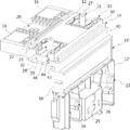
도 1은 본 발명에 의한 배터리부착형 퓨즈유니트의 바람직한 실시례를 보인 사시도.
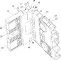
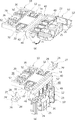
도 2는 본 발명 실시례의 구성을 보인 분해사시도.
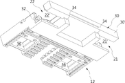
도 3은 본 발명 실시례의 구성을 저면에서 보인 저면사시도.
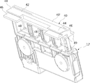
도 4는 본 발명 실시례를 구성하는 제1하우징의 구조를 보인 사시도.
도 5는 본 발명 실시례를 구성하는 제2하우징의 구조를 보인 사시도.
도 6은 본 발명 실시례의 구성을 보인 단면도.
도 7은 본 발명 실시례의 퓨즈유니트를 제조하는 것을 보인 설명도.1 is a perspective view showing a battery-attached fuse unit according to a preferred embodiment of the present invention.
2 is an exploded perspective view showing a configuration of an embodiment of the present invention.
3 is a bottom perspective view showing the configuration of an embodiment of the present invention in a bottom view.
4 is a perspective view showing a structure of a first housing constituting an embodiment of the present invention.
5 is a perspective view showing a structure of a second housing constituting an embodiment of the present invention.
6 is a sectional view showing the configuration of an embodiment of the present invention.
7 is an explanatory view showing the manufacture of a fuse unit according to an embodiment of the present invention;
이하, 본 발명의 일부 실시례들을 예시적인 도면을 통해 상세하게 설명한다. 각 도면의 구성요소들에 참조부호를 부가함에 있어서, 동일한 구성요소들에 대해서는 비록 다른 도면상에 표시되더라도 가능한 한 동일한 부호를 가지도록 하고 있음에 유의해야 한다. 또한, 본 발명의 실시례를 설명함에 있어, 관련된 공지구성 또는 기능에 대한 구체적인 설명이 본 발명의 실시례에 대한 이해를 방해한다고 판단되는 경우에는 그 상세한 설명은 생략한다.Hereinafter, some embodiments of the present invention will be described in detail with reference to exemplary drawings. It should be noted that, in adding reference numerals to the constituent elements of the drawings, the same constituent elements are denoted by the same reference numerals even though they are shown in different drawings. In the following description of the embodiments of the present invention, a detailed description of known functions and configurations incorporated herein will be omitted when it may make the understanding why the present invention is not intended to be interpreted.
또한, 본 발명의 실시례의 구성 요소를 설명하는 데 있어서, 제 1, 제 2, A, B, (a), (b) 등의 용어를 사용할 수 있다. 이러한 용어는 그 구성 요소를 다른 구성 요소와 구별하기 위한 것일 뿐, 그 용어에 의해 해당 구성 요소의 본질이나 차례 또는 순서 등이 한정되지 않는다. 어떤 구성 요소가 다른 구성요소에 "연결", "결합" 또는 "접속"된다고 기재된 경우, 그 구성 요소는 그 다른 구성요소에 직접적으로 연결되거나 접속될 수 있지만, 각 구성 요소 사이에 또 다른 구성 요소가 "연결", "결합" 또는 "접속"될 수도 있다고 이해되어야 할 것이다.In describing the components of the embodiment of the present invention, terms such as first, second, A, B, (a), and (b) may be used. These terms are intended to distinguish the constituent elements from other constituent elements, and the terms do not limit the nature, order or order of the constituent elements. When a component is described as being "connected", "coupled", or "connected" to another component, the component may be directly connected or connected to the other component, Quot; may be "connected," "coupled," or "connected. &Quot;
도면들에 도시된 바에 따르면, 본 발명의 퓨즈유니트는 크게 제1몸체부(10)와 제2몸체부(10')로 나누어진다. 상기 제1몸체부(10)와 제2몸체부(10')는 도시된 실시례에서는 서로 직교하게 만들어진다. 상기 제1몸체부(10)와 제2몸체부(10')는 배터리의 외면에서 서로 직교하게 인접한 2면에 각각 안착되어 고정된다. 만약 상기 배터리의 인접하는 2개의 외면이 서로 직교하지 않고 다른 각도를 가진다면 상기 제1몸체부(10)와 제2몸체부(10')가 형성하는 각도도 그와 같이 되면 된다.As shown in the drawings, the fuse unit of the present invention is roughly divided into a
상기 제1몸체부(10)의 외관을 제1하우징(12)이 형성하고, 상기 제2몸체부(10')의 외관을 제2하우징(12')이 형성하는데, 이들 하우징(12,12')은 절연성 합성수지로 만들어진다. 상기 제1 및 제2하우징(12')의 내부에는 버스바(14)가 위치된다. 상기 버스바(14)는 상기 제1 및 제2 하우징(12,12')을 형성하는 사출금형 내에 안착되어 상기 제1 및 제2 하우징(12,12')과 일체로 만들어진다. 상기 버스바(14)는 도전성 금속재질로 만들어진다.The outer appearance of the
상기 버스바(14)의 구성이 도 2나 도 6 등에 잘 도시되어 있는데, 실제 퓨즈유니트가 완성된 상태에서는 상기 버스바(14)는 전체적으로 횡단면이 'ㄱ'자 단면을 가진다. 즉 아래에서 설명될 연결절곡부(54)를 기준으로 절곡되어 있다. 물론, 상기 배터리의 인접하는 2개의 외면이 만나는 각도에 따라 상기 버스바(14)의 연결절곡부(54)가 절곡된 각도가 달라진다. 상기 버스바(14)는 제1 및 제2 하우징(12,12')을 형성하기 위한 금형 내에 놓여질 때는 절곡되지 않은 상태이나, 제1 및 제2 하우징(12,12')의 형성 후에는 소정의 각도를 가지도록 절곡된다.The configuration of the
상기 제1하우징(12)의 일단부 양측에는 제1용단부커버(16)가 설치되어 아래에서 설명될 용단공간(36)의 내부를 볼 수 있도록 한다. 상기 제1용단부커버(16)는 투명재질로 만들어지는 것이 좋다. 상기 제2하우징(12')에도 제2용단부커버(16')가 설치되는데, 아래에서 설명될 용단공간(44)의 내부를 볼 수 있도록, 제2용단부커버(16')도 투명재질로 만들어지는 것이 좋다. 상기 제1 및 제2 용단부커버(16,16')의 횡단면은 'ㄷ'자 형상으로 되어 각각 상기 제1하우징(12)과 제2하우징(12')의 양측 외면에서 용단공간(36,44)을 볼 수 있도록 한다.On both sides of one end of the
상기 제1몸체부(10)의 일측 단부 중간, 즉 상기 용단공간(36)의 사이에는 입력단자결합부(20)가 형성된다. 상기 입력단자결합부(20)에는 배터리 단자(도시되지 않음)가 관통하여 전기적으로 연결된다. 상기 입력단자결합부(20)에는 상기 버스바(14)의 입력단자(50)가 노출되어 있다.The input
상기 제1몸체부(10)의 타측 단부 양단에는 제1출력부(21)와 제2출력부(22)가 형성된다. 상기 제1출력부(21)와 제2출력부(22)는 부하측과의 연결을 위한 부분으로, 여기서는 단자볼트(27)가 돌출되어 있어, 외부의 링터미널(도시되지 않음)이 너트에 의해 결합되어 부하측과 전기적으로 연결된다. 여기서 상기 제1출력부(21)와 제2출력부(22)로 전달되는 전원의 차단은 상기 2개의 제1용단부커버(16)에 의해 차폐되어 있는 용단부(52)가 과부하시에 녹아 끊어짐에 의해 이루어진다.The
상기 제2몸체부(10')에는 제3출력부에서 제6출력부(23,24,25,26)가 형성되어 있다. 이들 다수개의 출력부(23,24,25,26)로 전달되는 전원의 차단은 제2용단부커버(16')에 의해 차폐되어 있는 용단공간(44)내에 있는 용단부(52)들이 과부하시에 녹아 끊어짐에 의해 이루어진다.In the second body portion 10 ',
단자볼트(27)의 구성은 다음과 같다. 상기 단자볼트(27)는 몸체부(28)와 머리부(29)로 구성된다. 상기 몸체부(28)에는 소정의 영역에 걸쳐서 나사부가 형성된다. 상기 나사부는 상기 몸체부(28)의 외면에 형성된다. 상기 머리부(29)는 상기 몸체부(28)의 일단부에 일체로 형성된다. 상기 머리부(29)는 본 실시례에서는 납작한 육면체로 된다. 상기 머리부(29)의 양측 외면에는 걸이채널(29')이 형성되어 있다. 상기 걸이채널(29')은 상기 머리부(29)의 양측 외면의 일측 끝에서 타측 끝까지 형성된다. 참고로, 상기 제3출력부(23)와 제4출력부(24)에 사용되는 단자볼트(27)는 머리부(29)의 구성이 제1출력부(21)와 제2출력부(22)에 사용되는 것과 조금 다르게 되어 있다. 이는 제1출력부(21)와 제2출력부(22)에서 사용되는 단자볼트(27)는 제1하우징(12)의 형성 이후에 제1관통부(21')와 제2관통부(22')에 슬라이딩 삽입될 수 있도록 하기 위한 것이다. 즉, 머리부(29)의 구성을 납작한 육면체로 만들었다.The configuration of the
여기서 상기 제1하우징(12)의 구성을 보다 상세하게 설명한다. 도 4에는 제1하우징(12)의 구성이 잘 도시되어 있는데, 상기 제1하우징(12)의 일측 단부에는 제1단부대(30)가 형성되어 있다. 상기 제1단부대(30)는 대략 사각바아 형상으로 되고, 그 일측 외면을 통해 상기 버스바(14)가 외부로 돌출되어 제2하우징(12')의 내부로 들어간다. 상기 제1단부대(30)에서 상기 버스바(14)가 돌출되는 외면은 제1단부면(30')으로 한다. 상기 제1단부면(30')은 금형에서 제1하우징(12)과 제2하우징(12')이 만들어졌을 때, 제2하우징(12')의 제2단부면(40')과 마주보게 된다. 하지만, 상기 버스바(14)가 절곡된 이후에는, 본 실시례에서는 이들 면(30',40')이 바라보는 방향은, 도 1 등에서 볼 수 있는 바와 같이, 서로 직교하는 방향이다.Here, the structure of the
상기 제1하우징(12)에서 상기 제1단부대(30)에 인접하여서는 상기 제1출력부(21)와 제2출력부(22)의 형성을 위한 제1관통부(21')와 제2관통부(22')가 제1하우징(12)을 상하로 관통함과 동시에 제1하우징(12)의 가장자리까지 개방되어 형성된다. 상기 제1관통부(21')에는 제1출력부(21)가 형성되고, 상기 제2관통부(22')에는 제2출력부(22)가 형성된다.A first through hole 21 'for forming the
상기 제1관통부(21')와 제2관통부(22')의 내면에는 각각 걸이리브(32)가 돌출되어 있다. 상기 걸이리브(32)는 상기 제2몸체부(10') 방향으로 연장되게 상기 제1관통부(21')와 제2관통부(22')의 일측 내면을 따라 길게 형성된다. 상기 걸이리브(32)는 아래에서 설명될 단자볼트(27)의 일측 걸이채널(29')에 걸어진다. 물론, 상기 걸이리브(32)가 반드시 있어서 상기 단자볼트(27)의 일측 걸이채널(29')에 걸어져야 하는 것은 아니다.A hooking
상기 제1하우징(12)에는, 도 4에 잘 도시된 바와 같이, 상기 제1단부대(30) 하부에 돌출되어 결합안내리브(34)가 있다. 상기 결합안내리브(34)는 2개가 한 쌍으로 되어 소정의 간격을 두고 돌출되어 있다. 상기 결합안내리브(34)는 제2하우징(12')과 제1하우징(12)이 서로 상대 이동을 하지 않도록 하는 역할을 한다. 특히 상기 결합안내리브(34)는 상기 제1하우징(12)과 제2하우징(12')이 도 1의 화살표 A 방향으로 상대 이동되는 것을 방지하는 역할을 한다.As shown in FIG. 4, the
한편, 상기 제1용단부커버(16)들이 설치되어 차폐되는 부분에는 용단공간(36)이 각각 형성되어 있다. 상기 용단공간(36)은 상기 제1하우징(12)을 관통하여 형성되어 있다. On the other hand, a
다음으로, 상기 제2하우징(12')에는, 도 5에 잘 도시된 바와 같이, 일측 단부에 제2단부대(40)가 형성되어 있다. 상기 제2단부대(40)도 대략 사각바아 형상이다. 상기 제2단부대(40)에서 상기 버스바(14)가 돌출되는 면이 제2단부면(40')이다. Next, in the second housing 12 ', as shown in FIG. 5, a
상기 제2단부대(40)에서 일측으로 돌출되게 결합대(42)가 있다. 본 실시례에서는 상기 결합대(42)는 상기 제2단부대(40)에 직교하게 된다. 이는 상기 버스바(14)가 연결절곡부(54)를 기준으로 직각으로 절곡되었기 때문이다. 상기 결합대(42)의 양측에는 제2걸이리브(44)가 돌출되어 있다. 상기 제2걸이리브(44)는 상기 제1하우징(12)의 제1걸이리브(32)와 마주보게 형성되는 것이다. 상기 제2걸이리브(44)는 상기 단자볼트(27)의 걸이채널(29')에 걸어지는 것이다. 상기 제2걸이리브(44)가 상기 단자볼트(27)의 걸이채널(29')에 걸어짐에 의해 상기 제1몸체부(10)와 제2몸체부(10') 사이의 각도가 견고하게 유지될 수 있게 된다. 상기 제2걸이리브(44)는 상기 제1 및 제2 출력부(21,22)와 대응되는 위치에 형성된다.And a
상기 제2걸이리브(44)와 평행하게 상대적으로 하부에는 제2결합안내리브(46)가 있다. 상기 제2결합안내리브(46)는 상기 결합대(42)의 양단에 하나씩 구비되어 그 사이에 상기 제1결합안내리브(34)가 위치하도록 한다. 상기 제1결합안내리브(34)가 상기 제2결합안내리브(46)의 사이에 위치되어, 도 1의 화살표 A방향으로의 제1 몸체부(10)와 제2몸체부(10')의 상대 이동이 방지된다.And a second
상기 제2하우징(12')에는 다수개의 용단공간(48)이 나란히 형성되는데, 상기 용단공간(48)을 외부와 구획하도록 구획벽(49)이 형성된다. 상기 구획벽(49)은 상기 제2하우징(12')의 용단공간(48) 가장자리를 둘러 형성되는데, 상기 제2하우징(12')의 양측 외면에 각각 돌출되어 형성된다. 상기 제2하우징(12')의 양측 외면에는 각각 'ㄷ'자 형상으로 구획벽(49)이 형성되어 있다. 상기 용단공간(48)을 상기 제2용단부커버(16')가 차폐하는데, 상기 제2하우징(12')의 양측 외면과 일 측면에서 상기 용단공간(49)을 동시에 차폐하게 된다.In the second housing 12 ', a plurality of fusing
한편, 상기 버스바(14)의 구성을 보다 상세하게 설명한다. 도 2에 따르면, 상기 버스바(14)에서 상기 입력단자결합부(20)에 해당되는 위치에는 입력단자(50)가 형성된다. 상기 입력단자(50)는 상기 제1하우징(12)의 외부로 노출되는데, 그 중앙에 체결공(도면부호 부여 않음)이 형성되어 있다.The configuration of the
상기 버스바(14)중에서 제1몸체부(10)에 위치되는 부분에는 상기 제1하우징(12)의 용단공간(36)에 위치되도록 용단부(52)가 형성된다. 상기 용단부(52)는 각각 제1출력부(21)와 제2출력부(22)에 연결되는 부하에 과부하가 걸렸을 때 녹아 끊어지는 부분이다.A
상기 버스바(14)중에서 제2몸체부(10')에 위치되는 부분에는 상기 제2하우징(12')의 용단공간(44)에 위치하도록 용단부(52')가 형성된다. 상기 용단부(52')는 다수개가 나란히 형성된다.A fusing end portion 52 'is formed at a portion of the
상기 버스바(14)에는 연결절곡부(54)가 있는데, 상기 연결절곡부(54)는 제1몸체부(10)를 구성하는 부분과 제2몸체부(10')를 구성하는 부분이 소정의 각도를 가지고 연결되도록 절곡되는 부분이다.The
상기 제1출력부(21)와 제2출력부(22)에 대응되는 위치에는 각각 제1출력단자(55)와 제2출력단자(56)가 있다. 상기 제1출력단자(55)와 제2출력단자(56)에는 연결볼트가 관통되는 제1단자공(55')과 제2단자공(56')이 형성된다. 이들 제1단자공(55')과 제2단자공(56')은 각각 상기 버스바(14)의 양측 가장자리로 개방된다. 이는 상기 제1하우징(12)의 제작 후에 상기 제1출력부(21)와 제2출력부(22)를 구성하는 단자볼트(27)를 제1단자공(55')과 제2단자공(56')을 관통하도록 삽입할 수 있게 하기 위함이다.A
상기 제3출력부에서 제6출력부(23,24,25,26)에 대응되는 위치에는 제3출력단자에서 제6출력단자(57,58,59,60)가 형성되어 있다. 여기서 제3출력단자(57)와 제4출력단자(58)에는 연결볼트가 관통하는 통공이 형성되어 있고, 상기 제5출력단자(59)와 제6출력단자(60)는 탭터미널 형상으로 만들어진다.A sixth output terminal (57, 58, 59, 60) is formed at the third output terminal at a position corresponding to the sixth output terminal (23, 24, 25, 26). The
이하 상기한 바와 같은 구성을 가지는 본 발명에 의한 배터리부착형 퓨즈유니트가 제조되고 사용되는 것을 상세하게 설명한다.Hereinafter, a battery-attached fuse unit according to the present invention having the above-described configuration will be described in detail.
본 발명의 퓨즈유니트는 상기 버스바(14)가 평평하게 된 상태, 즉 상기 연결절곡부(54)가 절곡되지 않은 상태로 제1하우징(12)과 제2하우징(12')을 동시에 성형하기 위한 사출금형 내에 위치되도록 한다. 물론, 제3출력부(23)와 제4출력부(24)를 구성하는 단자볼트(27)도 함께 사출금형 내에 위치되도록 한다. 따라서, 본 발명에서는 상기 제1용단부커버(16)와 제2용단부커버(16') 그리고 제1출력부(21)와 제2출력부(22)에서 사용되는 단자볼트(27)를 제외한 나머지 구성은 일체로 만들어진다.The fuse unit of the present invention is configured such that the
이와 같이 하여 버스바(14)의 연결절곡부(54)가 노출된 상태로 제1하우징(12)과 제2하우징(12')이 만들어지고 나면, 도 7의 (a)에 도시된 상태로 된다. 다음으로 상기 연결절곡부(54)를 소정의 각도, 본 실시례에서는 직각으로 절곡하면 도 7의 (b)의 상태가 된다. When the
다음으로, 상기 제1출력부(21)와 제2출력부(22)에 각각 단자볼트(27)를 삽입한다. 상기 단자볼트(27)의 머리부(29)가 상기 제1관통부(21')와 제2관통부(22')로 들어가면서 상기 걸이채널(29')에 제1걸이리브(32)와 제2걸이리브(44)가 안착된다. 이와 같이 양측의 걸이채널(29')에 제1걸이리브(32)와 제2걸이리브(44)가 안착되면 상기 제1하우징(12)과 제2하우징(12') 사이의 각도가 그대로 유지될 수 있게 된다.Next,
상기 제1출력부(21)와 제2출력부(22)에 상기 단자볼트(27)를 삽입하고 나면, 상기 제1용단부커버(16)와 제2용단부커버(16')를 제1하우징(12)과 제2하우징(12')에 장착한다. 물론, 상기 단자볼트(27) 삽입 전에 상기 용단부커버(16,16')를 먼저 장착할 수도 있다.After inserting the
한편, 위에서 설명한 바와 같이, 상기 제1출력부(21)와 제2출력부(22)에 각각 단자볼트(27)를 삽입하여, 제1하우징(12)의 제1걸이리브(32)가 일측 걸이채널(29')에 걸어지고, 제2하우징(12')의 제2걸이리브(44)가 타측 걸이채널(29')에 걸어지게 되면, 제1하우징(12)과 제2하우징 사이의 상대 위치가 고정된다.As described above, the
이에 더해 상기 제1결합안내리브(34)가 상기 제2결합안내리브(46)의 사이에 위치함에 의해 상기 단자볼트(27)가 삽입되는 방향과 그 반대방향으로 제1하우징(12)과 제2하우징(12')이 상대 이동하는 것이 방지될 수 있다.In addition, since the first
따라서, 본 발명의 퓨즈 유니트에서 제1하우징(12)과 제2하우징(12') 사이의 상대 위치, 또는 제1몸체부(10)와 제2몸체부(10') 사이의 상대 위치가 견고하게 유지될 수 있게 된다.Accordingly, in the fuse unit of the present invention, the relative position between the
한편, 본 발명의 배터리부착형 퓨즈유니트는 상기 입력단자결합부(20)에 배터리단자가 관통하여 전기적인 결합이 이루어지고, 상기 제1에서 제6출력부(21,22,23,24,25,26)에 부하측과 연결되는 터미널 또는 커넥터 등이 연결되어 부하측으로 전원을 공급하게 되는데, 부하측에 과부하가 걸리게 되는 각각의 해당되는 용단부(52,52')가 녹아 끊어져서 더 이상의 전원공급을 차단하게 된다.In the meantime, in the battery-attached fuse unit of the present invention, the battery terminals are electrically connected to the input
이상의 설명은 본 발명의 기술 사상을 예시적으로 설명한 것에 불과한 것으로서, 본 발명이 속하는 기술 분야에서 통상의 지식을 가진 자라면 본 발명의 본질적인 특성에서 벗어나지 않는 범위에서 다양한 수정 및 변형이 가능할 것이다. 따라서, 본 발명에 개시된 실시례들은 본 발명의 기술 사상을 한정하기 위한 것이 아니라 설명하기 위한 것이고, 이러한 실시례에 의하여 본 발명의 기술 사상의 범위가 한정되는 것은 아니다. 본 발명의 보호 범위는 아래의 청구범위에 의하여 해석되어야 하며, 그와 동등한 범위 내에 있는 모든 기술 사상은 본 발명의 권리범위에 포함되는 것으로 해석되어야 할 것이다.The foregoing description is merely illustrative of the technical idea of the present invention, and various changes and modifications may be made by those skilled in the art without departing from the essential characteristics of the present invention. Therefore, the embodiments disclosed in the present invention are not intended to limit the scope of the present invention but to limit the scope of the technical idea of the present invention. The scope of protection of the present invention should be construed according to the following claims, and all technical ideas within the scope of equivalents should be construed as falling within the scope of the present invention.
도시된 실시례에서는 출력부가 6개가 있으나, 그 갯수는 상관이 없다. 즉, 더 많은 출력부가 있거나 더 적은 출력부가 있을 수 있다.In the illustrated embodiment, there are six output units, but the number of output units is irrelevant. That is, there may be more output parts or fewer output parts.
그리고, 도시된 실시례에서는 상기 제1몸체부(10)에 구비되는 단자볼트(27)를 사용하여 제1몸체부(10)와 제2몸체부(10')의 상대 위치를 고정하였으나, 상기 단자볼트(27)가 상기 제2몸체부(10')에 있을 수도 있다. 이 경우에는 상기 단자볼트(27)가 설치되는 관통부(21',22')의 구성이나 제2걸이리브(44) 그리고 일측으로 개방된 제1단자공(55')과 제2단자공(56')이 반대쪽에 있게 된다.In the illustrated embodiment, the relative positions of the
또한, 도시된 실시례에서는 상기 제1몸체부(10)에 설치된 상기 단자볼트(27)에 제2몸체부(10)에 있는 제2걸이리브(44)가 걸어졌으나, 상기 제2걸이리브(44) 대신에 상기 제2몸체부(10)의 일측이 걸어질 수 있다.In the illustrated embodiment, the second hooking
그리고, 도시된 실시례에서는 상기 제1결합안내리브(34)가 2개가 구비되어 있으나, 상기 제1결합안내리브(34)는 상기 제2결합안내리브(46)의 사이에 위치되는 하나로 만들어질 수 있다. In the illustrated embodiment, two of the first
10: 제1몸체부
10': 제2몸체부
12: 제1하우징
12': 제2하우징
14: 버스바
16: 제1용단부커버
16': 제2용단부커버
20: 입력단자결합부
21: 제1출력부
21': 제1관통부
22: 제2출력부
22': 제2관통부
23: 제3출력부
24: 제4출력부
25: 제5출력부
26: 제6출력부
27: 단자볼트
28: 몸체부
29: 머리부
29': 걸이채널
30: 제1단부대
30': 제1단부면
32: 제1걸이리브
34: 제1결합안내리브
36: 용단공간
40: 제2단부대
40': 제2단부면
42: 결합대
44: 제2걸이리브
46: 제2결합안내리브
48: 용단공간
50: 입력단자
52: 용단부
52': 용단부
54: 연결절곡부
55: 제1출력단자
55': 제1단자공
56: 제2출력단자
56': 제2단자공
57: 제3출력단자
58: 제4출력단자
59: 제5출력단자
60: 제6출력단자10: first body part 10 ': second body part
12: first housing 12 ': second housing
14: bus bar 16: first fuselage cover
16 ': second fuse cover 20: input terminal coupling portion
21: first output section 21 ': first penetration section
22: second output portion 22 ': second through portion
23: third output section 24: fourth output section
25: fifth output section 26: sixth output section
27: terminal bolt 28:
29: head 29 ': hook channel
30: first end bag 30 ': first end face
32: first hook rib 34: first coupling guide rib
36: Fusing space 40: Second-end bag
40 ': second end face 42:
44: second hook rib 46: second coupling guide rib
48: terminal space 50: input terminal
52: fusing part 52 ': fusing part
54: connecting bend 55: first output terminal
55 ': first terminal hole 56: second output terminal
56 ': second terminal hole 57: third output terminal
58: fourth output terminal 59: fifth output terminal
60: sixth output terminal
Claims (10)
상기 버스바의 일측이 내부에 위치되고 외관을 제1하우징이 형성하는 제1몸체부와,
상기 버스바의 타측이 내부에 위치되고 외관을 제2하우징이 형성하며 상기 제1몸체부와 소정의 각도를 형성하는 제2몸체부를 포함하고,
상기 제1몸체부나 제2몸체부중 일측에 형성된 적어도 하나의 출력부에 해당하는 위치에 설치된 단자볼트에 상기 단자볼트가 설치된 반대쪽인 제2몸체부나 제1몸체부의 일측이 걸어지는 배터리부착형 퓨즈유니트.
A bus bar in which an input terminal is formed on one side and at least one output terminal is formed on the other side,
A first body portion having one side of the bus bar located inside and having an outer appearance formed by the first housing,
And a second body part having the other side of the bus bar located inside and having an outer appearance forming a second housing and forming a predetermined angle with the first body part,
A second body part opposite to the terminal bolt installed on the terminal bolt installed at a position corresponding to at least one output part formed at one side of the first body part or the second body part, and a battery attaching type fuse unit .
The connector according to claim 1, wherein the terminal bolt comprises a body portion having a threaded portion formed on an outer surface thereof and a head portion integrally formed at one end of the body portion, and a hooking channel is formed on the outer surface of the head portion, Wherein the first hooking rib and the second hooking rib of the second body part are hooked.
The connector according to claim 2, wherein the terminal bolt is provided at a position of an output portion formed in the first housing or the second housing, wherein the output portion is formed with a penetrating portion penetrating through the first housing or the second housing, Wherein the first hanger rib is formed on the first hanger rib.
[4] The apparatus of claim 3, wherein the bus bar is inserted into the injection mold in a flat state in which the first housing and the second housing are formed at the same time so that the first and second housings are formed between the first and second housings Wherein the connection bending portion is bent at a predetermined angle.
The portable terminal as claimed in claim 4, wherein the first housing has a first end having a first end surface through which the bus bar is exposed to the outside, and a second end Wherein the first end face and the second end face of the second end bag have a predetermined angle with respect to the first end face and the second end face.
[2] The apparatus as claimed in claim 1, wherein the bus bar is formed with a connecting bending part bent at a predetermined angle while connecting a part located in the first body part and a part located in the second body part, Terminal and at least one output portion are formed and at least one output portion is formed on the other side.
The connector according to any one of claims 1 to 6, wherein a first coupling guide rib and a second coupling guide rib are formed at positions corresponding to each other of the first housing and the second housing, Wherein the relative movement between the first housing and the second housing is regulated by the second coupling guide ribs at both ends of the first coupling guide rib, respectively.
상기 버스바의 일측이 절연재질로 된 제1하우징의 내부에 구비되어 형성된 제1몸체부와,
상기 버스바의 타측이 절연재질로 된 제2하우징의 내부에 구비되어 형성된 제2몸체부와,
상기 출력단자중 적어도 하나 이상에 설치되고 머리부의 양측 외면에 상기 출력단자가 설치된 제1몸체부나 제2몸체부의 반대쪽에 해당되는 제2몸체부나 제1몸체부의 일측이 걸어져서 제1몸체부와 제2몸체부 사이의 상대 위치를 유지하게 하는 단자볼트를 포함하는 배터리부착형 퓨즈유니트.
A bus bar having a free end, an input terminal and an output terminal formed on one side and a connecting bend on one side so that both sides have a predetermined angle with respect to the connecting bend,
A first body part having one side of the bus bar formed inside a first housing made of an insulating material,
A second body part formed on the other side of the bus bar and formed in a second housing made of an insulating material,
One end of the first body portion or the second body portion, which is opposite to the first body portion or the second body portion provided with the output terminal, is installed on at least one of the output terminals, And a terminal bolt for maintaining a relative position between the body portions.
9. The connector according to claim 8, wherein the terminal bolt comprises a body portion having a threaded portion formed on an outer surface thereof and a head portion integrally formed at one end of the body portion, And a second hanging rib formed on the second body portion.
The portable terminal according to claim 8 or 9, wherein a first coupling guide rib and a second coupling guide rib are formed at positions corresponding to each other of the first housing and the second housing to regulate the relative movement of the first housing and the second housing Wherein the second coupling guide ribs are provided at both ends of the first coupling guide rib to restrict relative movement between the first housing and the second housing.
Priority Applications (1)
| Application Number | Priority Date | Filing Date | Title |
|---|---|---|---|
| KR1020150160241A KR20170056877A (en) | 2015-11-16 | 2015-11-16 | Fuse unit mounted on battery |
Applications Claiming Priority (1)
| Application Number | Priority Date | Filing Date | Title |
|---|---|---|---|
| KR1020150160241A KR20170056877A (en) | 2015-11-16 | 2015-11-16 | Fuse unit mounted on battery |
Publications (1)
| Publication Number | Publication Date |
|---|---|
| KR20170056877A true KR20170056877A (en) | 2017-05-24 |
Family
ID=59051295
Family Applications (1)
| Application Number | Title | Priority Date | Filing Date |
|---|---|---|---|
| KR1020150160241A KR20170056877A (en) | 2015-11-16 | 2015-11-16 | Fuse unit mounted on battery |
Country Status (1)
| Country | Link |
|---|---|
| KR (1) | KR20170056877A (en) |
Cited By (3)
| Publication number | Priority date | Publication date | Assignee | Title |
|---|---|---|---|---|
| WO2018221818A1 (en) * | 2017-05-29 | 2018-12-06 | 주식회사 엘지화학 | Battery module |
| WO2019124876A1 (en) * | 2017-12-19 | 2019-06-27 | 주식회사 엘지화학 | Battery module having bus bar assembly |
| CN113632310A (en) * | 2019-03-28 | 2021-11-09 | Cps 科技控股有限公司 | Flexible circuit with fuse, bus bar holder including lead-in structure, conductive assembly with bus bar, and battery including conductive assembly |
-
2015
- 2015-11-16 KR KR1020150160241A patent/KR20170056877A/en not_active Application Discontinuation
Cited By (6)
| Publication number | Priority date | Publication date | Assignee | Title |
|---|---|---|---|---|
| WO2018221818A1 (en) * | 2017-05-29 | 2018-12-06 | 주식회사 엘지화학 | Battery module |
| US11342631B2 (en) | 2017-05-29 | 2022-05-24 | Lg Energy Solution, Ltd. | Battery module having a bus bar with a main frame and metal plates |
| WO2019124876A1 (en) * | 2017-12-19 | 2019-06-27 | 주식회사 엘지화학 | Battery module having bus bar assembly |
| US11139539B2 (en) | 2017-12-19 | 2021-10-05 | Lg Chem, Ltd. | Battery module having bus bar assembly |
| CN113632310A (en) * | 2019-03-28 | 2021-11-09 | Cps 科技控股有限公司 | Flexible circuit with fuse, bus bar holder including lead-in structure, conductive assembly with bus bar, and battery including conductive assembly |
| CN113632310B (en) * | 2019-03-28 | 2023-12-29 | Cps 科技控股有限公司 | Flexible circuit with fuse and battery |
Similar Documents
| Publication | Publication Date | Title |
|---|---|---|
| US7592892B2 (en) | Fusible link unit accommodated in in-vehicle electrical connection box | |
| US9716325B1 (en) | Electronic component unit and electrical connection box | |
| EP2871690B1 (en) | Bus bar module | |
| KR20140034055A (en) | Power cord | |
| US20160351368A1 (en) | Electrical connection box and wire harness | |
| US10297994B2 (en) | Substrate holding structure, electronic component module, and electrical connection box | |
| US9623816B2 (en) | Locking structure, electronic component unit and wire harness | |
| KR20170056877A (en) | Fuse unit mounted on battery | |
| US9368919B2 (en) | Plug connector comprising a protective conductor bridge | |
| EP3151345A1 (en) | Electric connector | |
| JP5667287B2 (en) | Electrical junction box | |
| WO2018008384A1 (en) | Terminal module and connector | |
| JP2014054005A (en) | Electric connection box | |
| JPWO2015029990A1 (en) | Connection structure between electronic parts and terminal fittings | |
| KR102338879B1 (en) | Fuse | |
| US11139135B2 (en) | Attachment structure between cover and housing, and fusible link unit | |
| KR200491844Y1 (en) | Series connection apparatus of battery module | |
| US9627869B2 (en) | Block for vehicle | |
| US9728365B2 (en) | Fuse, fuse box, and fuse device | |
| JP7115358B2 (en) | electronic module | |
| KR101810131B1 (en) | Connector | |
| KR102361579B1 (en) | Connector | |
| JP2016149302A (en) | Fuse unit | |
| KR20160020939A (en) | Fuse unit mounted on battery | |
| KR101342166B1 (en) | Connector |
Legal Events
| Date | Code | Title | Description |
|---|---|---|---|
| E902 | Notification of reason for refusal | ||
| E601 | Decision to refuse application |