EP3739662A2 - Battery module - Google Patents
Battery module Download PDFInfo
- Publication number
- EP3739662A2 EP3739662A2 EP20174634.4A EP20174634A EP3739662A2 EP 3739662 A2 EP3739662 A2 EP 3739662A2 EP 20174634 A EP20174634 A EP 20174634A EP 3739662 A2 EP3739662 A2 EP 3739662A2
- Authority
- EP
- European Patent Office
- Prior art keywords
- plate
- disposed
- battery module
- unit
- battery
- Prior art date
- Legal status (The legal status is an assumption and is not a legal conclusion. Google has not performed a legal analysis and makes no representation as to the accuracy of the status listed.)
- Pending
Links
Images


Classifications
-
- H—ELECTRICITY
- H01—ELECTRIC ELEMENTS
- H01M—PROCESSES OR MEANS, e.g. BATTERIES, FOR THE DIRECT CONVERSION OF CHEMICAL ENERGY INTO ELECTRICAL ENERGY
- H01M10/00—Secondary cells; Manufacture thereof
- H01M10/05—Accumulators with non-aqueous electrolyte
- H01M10/052—Li-accumulators
-
- H—ELECTRICITY
- H01—ELECTRIC ELEMENTS
- H01M—PROCESSES OR MEANS, e.g. BATTERIES, FOR THE DIRECT CONVERSION OF CHEMICAL ENERGY INTO ELECTRICAL ENERGY
- H01M10/00—Secondary cells; Manufacture thereof
- H01M10/60—Heating or cooling; Temperature control
- H01M10/61—Types of temperature control
- H01M10/613—Cooling or keeping cold
-
- H—ELECTRICITY
- H01—ELECTRIC ELEMENTS
- H01M—PROCESSES OR MEANS, e.g. BATTERIES, FOR THE DIRECT CONVERSION OF CHEMICAL ENERGY INTO ELECTRICAL ENERGY
- H01M10/00—Secondary cells; Manufacture thereof
- H01M10/42—Methods or arrangements for servicing or maintenance of secondary cells or secondary half-cells
- H01M10/48—Accumulators combined with arrangements for measuring, testing or indicating the condition of cells, e.g. the level or density of the electrolyte
- H01M10/482—Accumulators combined with arrangements for measuring, testing or indicating the condition of cells, e.g. the level or density of the electrolyte for several batteries or cells simultaneously or sequentially
-
- H—ELECTRICITY
- H01—ELECTRIC ELEMENTS
- H01M—PROCESSES OR MEANS, e.g. BATTERIES, FOR THE DIRECT CONVERSION OF CHEMICAL ENERGY INTO ELECTRICAL ENERGY
- H01M10/00—Secondary cells; Manufacture thereof
- H01M10/42—Methods or arrangements for servicing or maintenance of secondary cells or secondary half-cells
- H01M10/48—Accumulators combined with arrangements for measuring, testing or indicating the condition of cells, e.g. the level or density of the electrolyte
- H01M10/486—Accumulators combined with arrangements for measuring, testing or indicating the condition of cells, e.g. the level or density of the electrolyte for measuring temperature
-
- H—ELECTRICITY
- H01—ELECTRIC ELEMENTS
- H01M—PROCESSES OR MEANS, e.g. BATTERIES, FOR THE DIRECT CONVERSION OF CHEMICAL ENERGY INTO ELECTRICAL ENERGY
- H01M10/00—Secondary cells; Manufacture thereof
- H01M10/60—Heating or cooling; Temperature control
- H01M10/64—Heating or cooling; Temperature control characterised by the shape of the cells
- H01M10/647—Prismatic or flat cells, e.g. pouch cells
-
- H—ELECTRICITY
- H01—ELECTRIC ELEMENTS
- H01M—PROCESSES OR MEANS, e.g. BATTERIES, FOR THE DIRECT CONVERSION OF CHEMICAL ENERGY INTO ELECTRICAL ENERGY
- H01M10/00—Secondary cells; Manufacture thereof
- H01M10/60—Heating or cooling; Temperature control
- H01M10/65—Means for temperature control structurally associated with the cells
- H01M10/655—Solid structures for heat exchange or heat conduction
- H01M10/6554—Rods or plates
- H01M10/6555—Rods or plates arranged between the cells
-
- H—ELECTRICITY
- H01—ELECTRIC ELEMENTS
- H01M—PROCESSES OR MEANS, e.g. BATTERIES, FOR THE DIRECT CONVERSION OF CHEMICAL ENERGY INTO ELECTRICAL ENERGY
- H01M10/00—Secondary cells; Manufacture thereof
- H01M10/60—Heating or cooling; Temperature control
- H01M10/65—Means for temperature control structurally associated with the cells
- H01M10/655—Solid structures for heat exchange or heat conduction
- H01M10/6556—Solid parts with flow channel passages or pipes for heat exchange
-
- H—ELECTRICITY
- H01—ELECTRIC ELEMENTS
- H01M—PROCESSES OR MEANS, e.g. BATTERIES, FOR THE DIRECT CONVERSION OF CHEMICAL ENERGY INTO ELECTRICAL ENERGY
- H01M10/00—Secondary cells; Manufacture thereof
- H01M10/60—Heating or cooling; Temperature control
- H01M10/65—Means for temperature control structurally associated with the cells
- H01M10/656—Means for temperature control structurally associated with the cells characterised by the type of heat-exchange fluid
- H01M10/6567—Liquids
- H01M10/6568—Liquids characterised by flow circuits, e.g. loops, located externally to the cells or cell casings
-
- H—ELECTRICITY
- H01—ELECTRIC ELEMENTS
- H01M—PROCESSES OR MEANS, e.g. BATTERIES, FOR THE DIRECT CONVERSION OF CHEMICAL ENERGY INTO ELECTRICAL ENERGY
- H01M50/00—Constructional details or processes of manufacture of the non-active parts of electrochemical cells other than fuel cells, e.g. hybrid cells
- H01M50/20—Mountings; Secondary casings or frames; Racks, modules or packs; Suspension devices; Shock absorbers; Transport or carrying devices; Holders
- H01M50/204—Racks, modules or packs for multiple batteries or multiple cells
- H01M50/207—Racks, modules or packs for multiple batteries or multiple cells characterised by their shape
- H01M50/211—Racks, modules or packs for multiple batteries or multiple cells characterised by their shape adapted for pouch cells
-
- H—ELECTRICITY
- H01—ELECTRIC ELEMENTS
- H01M—PROCESSES OR MEANS, e.g. BATTERIES, FOR THE DIRECT CONVERSION OF CHEMICAL ENERGY INTO ELECTRICAL ENERGY
- H01M50/00—Constructional details or processes of manufacture of the non-active parts of electrochemical cells other than fuel cells, e.g. hybrid cells
- H01M50/20—Mountings; Secondary casings or frames; Racks, modules or packs; Suspension devices; Shock absorbers; Transport or carrying devices; Holders
- H01M50/262—Mountings; Secondary casings or frames; Racks, modules or packs; Suspension devices; Shock absorbers; Transport or carrying devices; Holders with fastening means, e.g. locks
- H01M50/264—Mountings; Secondary casings or frames; Racks, modules or packs; Suspension devices; Shock absorbers; Transport or carrying devices; Holders with fastening means, e.g. locks for cells or batteries, e.g. straps, tie rods or peripheral frames
-
- H—ELECTRICITY
- H01—ELECTRIC ELEMENTS
- H01M—PROCESSES OR MEANS, e.g. BATTERIES, FOR THE DIRECT CONVERSION OF CHEMICAL ENERGY INTO ELECTRICAL ENERGY
- H01M50/00—Constructional details or processes of manufacture of the non-active parts of electrochemical cells other than fuel cells, e.g. hybrid cells
- H01M50/20—Mountings; Secondary casings or frames; Racks, modules or packs; Suspension devices; Shock absorbers; Transport or carrying devices; Holders
- H01M50/284—Mountings; Secondary casings or frames; Racks, modules or packs; Suspension devices; Shock absorbers; Transport or carrying devices; Holders with incorporated circuit boards, e.g. printed circuit boards [PCB]
-
- H—ELECTRICITY
- H01—ELECTRIC ELEMENTS
- H01M—PROCESSES OR MEANS, e.g. BATTERIES, FOR THE DIRECT CONVERSION OF CHEMICAL ENERGY INTO ELECTRICAL ENERGY
- H01M50/00—Constructional details or processes of manufacture of the non-active parts of electrochemical cells other than fuel cells, e.g. hybrid cells
- H01M50/20—Mountings; Secondary casings or frames; Racks, modules or packs; Suspension devices; Shock absorbers; Transport or carrying devices; Holders
- H01M50/296—Mountings; Secondary casings or frames; Racks, modules or packs; Suspension devices; Shock absorbers; Transport or carrying devices; Holders characterised by terminals of battery packs
-
- H—ELECTRICITY
- H01—ELECTRIC ELEMENTS
- H01M—PROCESSES OR MEANS, e.g. BATTERIES, FOR THE DIRECT CONVERSION OF CHEMICAL ENERGY INTO ELECTRICAL ENERGY
- H01M50/00—Constructional details or processes of manufacture of the non-active parts of electrochemical cells other than fuel cells, e.g. hybrid cells
- H01M50/50—Current conducting connections for cells or batteries
- H01M50/569—Constructional details of current conducting connections for detecting conditions inside cells or batteries, e.g. details of voltage sensing terminals
-
- Y—GENERAL TAGGING OF NEW TECHNOLOGICAL DEVELOPMENTS; GENERAL TAGGING OF CROSS-SECTIONAL TECHNOLOGIES SPANNING OVER SEVERAL SECTIONS OF THE IPC; TECHNICAL SUBJECTS COVERED BY FORMER USPC CROSS-REFERENCE ART COLLECTIONS [XRACs] AND DIGESTS
- Y02—TECHNOLOGIES OR APPLICATIONS FOR MITIGATION OR ADAPTATION AGAINST CLIMATE CHANGE
- Y02E—REDUCTION OF GREENHOUSE GAS [GHG] EMISSIONS, RELATED TO ENERGY GENERATION, TRANSMISSION OR DISTRIBUTION
- Y02E60/00—Enabling technologies; Technologies with a potential or indirect contribution to GHG emissions mitigation
- Y02E60/10—Energy storage using batteries
Definitions
- This application relates to a battery module.
- secondary batteries may charge and discharge electrical energy.
- secondary batteries may be applied to various fields, for example, in the areas of digital cameras, mobile phones, notebook computers, hybrid vehicles, and the like.
- Examples of secondary batteries may include nickel-cadmium batteries, nickel-metal hydride batteries, nickel-hydrogen batteries, lithium secondary batteries, and the like.
- the pouched battery cells are provided as a plurality of pouched battery cell modules.
- the plurality of pouched battery cell modules may be configured to be connected and used as battery modules.
- the battery module requires a cooling system for cooling the battery cells accommodated therein.
- a cooling system for cooling the battery cells accommodated therein.
- Example embodiments of the present disclosure provide a battery module, capable of efficiently dissipating heat generated in a battery cell.
- a battery module includes a cell unit, including a plurality of battery cells disposed on both surfaces of a unit plate, and a case accommodating the cell unit.
- the unit plate includes a plurality of receiving spaces, in which the plurality of battery cells are disposed, and a connection member disposed between the receiving spaces to electrically connect the battery cells to each other.
- connection member may include a busbar, formed of a conductive material and spaced apart from the unit plate, and a bracket formed of an insulating material and disposed along a circumference of the busbar to be in contact with the unit plate when the connection member is coupled to the unit plate.
- the busbar may have both surfaces exposed outwardly of the bracket, and the plurality of battery cells may be connected to both surfaces of the bracket, respectively.
- the unit plate may have a plate portion, having a flat surface, and a side portion protruding upwardly and downwardly of the plate portion from both sides of the plate portion.
- the plurality of receiving spaces may be formed by the plate portion and the side portion.
- the battery module may further include an external side connection member disposed on an end portion of the unit plate to be electrically connected to the battery cell.
- the external side connection member may include a coupling terminal protruding outwardly of the unit plate to be used in an electrical connection to another cell unit.
- the battery module may further include a circuit board coupled to the unit plate to sense a voltage of the battery cells or to measure a temperature of the battery cells.
- the circuit board may be formed as a flexible printed circuit board (FPCB) to electrically connect the busbar to an external entity.
- FPCB flexible printed circuit board
- a portion disposed in the receiving space may be attached to an internal side surface of the side portion and may be formed to have a width less than a width of the side portion.
- the circuit board may further include a temperature sensor disposed to be in contact with the battery cell.
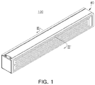
- FIG. 1 is a schematic perspective view of a battery module according to example embodiments
- FIG. 2 is an exploded perspective view of the battery module illustrated in FIG. 1 .
- FIG. 3 is an exploded perspective view of a cell unit illustrated in FIG. 2
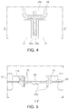
- FIG. 4 is a partially enlarged plan view of a connection member of FIG. 3
- FIG. 5 is a cross-sectional view taken along line I-I' in FIG. 4 .
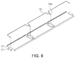
- FIG. 6 is an exploded perspective view of a unit plate and a circuit board illustrated in FIG. 3
- FIG. 7 is an exploded perspective view of a cell unit and a coupling unit illustrated in FIG. 2
- FIG. 8 is a cross-sectional view taken along line II-II' in FIG. 1 .
- a battery module 100 may have a substantially hexahedral shape and may include a cell assembly 60, in which a plurality battery cells 10 are coupled to each other, and a case 40 protecting the cell assembly 60 from the outside.
- the cell assembly 60 includes a plurality of cells units 20 coupled to each other.
- the cell unit 20 includes a unit plate 21, a plurality of battery cells 10 stacked on the unit plate 21, and a circuit board 28.
- the battery cell 10 may be provided as a plurality of battery cells stacked side by side, and may have a structure in which electrode leads 15 protrude outwardly of a body.
- the battery cell 10 may be, for example, a pouched secondary battery.
- the battery cell 10 may have a configuration in which an electrode assembly, not illustrated, is accommodated in a pouch 11.
- the electrode assembly may include a plurality of electrode plates and a plurality of electrode tabs, and may be accommodated in the pouch 11.
- Each of the electrode plates may include a positive electrode plate and a negative electrode plate, and the electrode assembly may have a configuration in which the positive electrode plate and the negative electrode plate are stacked such that relatively large surfaces oppose each other with a separator interposed therebetween.
- the positive electrode plate and the negative electrode plate may be formed to have structure in which an active material slurry is coated on a current collector.
- the slurry may be formed by stirring a granular active material, an auxiliary conductor, a binder, a plasticizer, and the like, in a state in which a solvent is added.
- a plurality of positive electrode plates and a plurality of negative electrode plates may be vertically stacked.
- the plurality of positive electrode plates and the plurality of negative electrode plates may be provided with electrode tabs, respectively, and may be in contact with each other with the same polarity to be in connected to the same electrode lead 15.
- two electrode leads 15 are disposed to face in opposing directions.
- the pouch 11 may be formed to have a container shape to provide an internal space in which the electrode assembly and electrolyte, not illustrated, are accommodated. In this case, a portion of the electrode lead 15 of the electrode assembly may be exposed outwardly of the pouch 11.
- the pouch 11 may be divided into a sealing portion 202 and an accommodation portion 204.
- the accommodation portion 204 may be formed to have a container shape to provide an internal space having a rectangular shape.
- the electrode assembly and the electrolyte may be accommodated in the internal space of the accommodation portion 204.
- the sealing portion 202 may be formed to have a flange shape extending outwardly of the accommodation portion 204 formed to have the container shape. Therefore, the sealing portion 202 may be disposed to have an edge shape along an external surface of the accommodation portion 204.
- a method of bonding sealing portions 202 to each other may be thermal fusion bonding, but the present disclosure is not limited thereto.
- the sealing portion 202 may be divided into a first sealing portion 2021, in which the electrode leads 15 are disposed, and a second sealing portion 2022 in which the electrode leads 15 are not disposed.
- the sealing portion 202 provided on four sides of the accommodation portion 204 includes two first sealing portions 2021, on which the electrode leads 15 are disposed, and two sealing portions 2022 on which the electrode leads 15 are not disposed.
- the battery cell 10 according to this embodiment may constitute the sealing portion 202 while being folded at least once to improve bonding reliability of the sealing portion 202 and to significantly reduce an area of the sealing portion 202.
- the battery cell 10 refers to a chargeable and dischargeable nickel metal hydride (Ni-MH) cell or lithium ion (Li-ion) cell, and generates current.
- Ni-MH nickel metal hydride
- Li-ion lithium ion
- the unit plate 21 includes a plate portion, with which the accommodation portion 204 of the battery cell 10 is in surface-contact, and side portions 23 disposed on both side surfaces of the plate portion 22 to protect the second sealing portion 2022 of the battery cell 10.
- the plate portion 22 is formed as a flat surface, and the side portion 23 is formed to protrude upwardly and downwardly of the plate portion 22 from both edge portions of the plate portion 22. Accordingly, the unit plate 21 may be formed such that a cross section, obtained by cutting the plate portion 22 and the side portion 23, has an H-beam shape.
- a connection portion 23a of the plate portion 22, connected to the side portion 23, may be formed to have a thickness greater than a thickness of the other portion to secure rigidity. In this case, heat of the plate portion 22 may be more effectively transferred to the side portion 23.
- the entire external surface of the side portion 23 is disposed to face the third plate 50 provided with a cooling device, and is disposed to be significantly close to the third plate 50. Therefore, the heat transferred to the side portion 23 may be rapidly discharged to an external entity through the third plate 50.
- connection portion 23a is not limited to a shape illustrated in the drawing, and may be variously modified as necessary, for example, forming an empty space in the connection portion 23a, or the like.
- the unit plate 21 has one surface, on which three battery cells 10 arranged in a line, and the other surface on which three battery cells 10 arranged in a line. Therefore, a total of six battery cells 10 are coupled to each other in a single unit plate 21.
- the present disclosure is not limited thereto, and one or two battery cells 10 may be disposed on each of both surfaces of the unit plate 21. As necessary, four or more battery cells 10 may be disposed on each of both surfaces of the unit plate 21.
- the unit plate 21 has three battery cell receiving spaces R1, R2, and R3 on one surface thereof.
- Each of the receiving spaces R1, R2, and R3 is defined by the plate portion 22 and the side portions 23.
- a connection member 26, to which the electrode lead 15 of the battery cell 10 is connected, is disposed between the receiving spaces R1, R2, and R3.
- connection member 26 may include a busbar 26a, formed of a conductive material, and a bracket 26b formed of an insulating material.
- the bracket 26b is disposed along the circumference of a busbar 26a, and is in contact with the unit plate 21 when the connection member 26 is coupled to the unit plate 21. Therefore, when the connection member 26 is coupled to the unit plate 21, the busbar 26a is spaced apart from the unit plate 21, and thus, is not in direct contact with or not electrically connected to the unit plate 21.
- the busbar 26a is formed of a flat metal plate, and has both surfaces exposed outwardly of the bracket 26b. Therefore, the battery cells 10 are bonded to both surfaces of the busbar 26a to be electrically connected to each other.
- two battery cells 10 are connected to one surface of the busbar 26a, and thus, a total of four battery cells 10 are connected to one busbar 26a.
- the electrode lead 15 of the battery cell 10 is bent to be bonded to the busbar 26a by welding, or the like.
- a method of bonding the electrode lead 15 of the battery cell 10 is not limited thereto.
- the busbar 26a and the bracket 26b may be manufactured through insert injection. However, a method of manufacturing the busbar 26a and the bracket 26b is not limited thereto, and the busbar 26a and the bracket 26b may be coupled to each other after being individually manufactured.
- the unit plate 21 is provided with a coupling hole 22a in which the connection member 26 is coupled between the receiving spaces R1, R2, and R3.
- the connection member 26 is coupled to the coupling hole 22a, the busbar 26a of the connection member 26 and the plate portion 22 may be disposed on the same plane, as illustrated in FIG. 5 .
- connection member 26 is coupled to the unit plate 21 in such a manner that the bracket 26b is fitted into the coupling hole 22a formed in the unit plate 21.
- An adhesive may be interposed between the connection member 26 and the unit plate 21 to stably couple the connection member 26 to the unit plate 21.
- an additional fixing member such as a bolt or a screw may be used.
- three battery cells 10, disposed in a line on one of the surfaces of the unit plate 21, are connected in series through the connection member 26. Accordingly, in a single cell unit 20, a plurality of battery cells 10 are connected in parallel while two battery cells 10 constitute a pair, and the three battery cells 10 connected in parallel are connected in series.
- the unit plate 21 is provided with fastening grooves 22b formed between the receiving spaces R1, R2, and R3 and the receiving space R1, R2, and R3, for example, in a portion in which the connection member 26 is disposed.
- the coupling groove 22b is formed in an external side of the connection member 26 as a groove formed in such a manner that the plate portion 22 and the side portion 23 are removed. Therefore, the fastening groove 22b is formed in such a manner that a width of the plate portion 22 or the cell unit 20 is reduced, and the side portion 23 is discontinuously disposed by the fastening groove 22b.
- the fastening groove 22b is a region in which a fastening portion 55 of the case 40, to be described later, is disposed. Therefore, the fastening groove 22b is formed to have a size at which the fastening portion 55 may be easily disposed.
- An external connection member 27 is disposed on both end portions of the unit plate 21. Similarly to the above-described connection member 26, the external connection member 27 may include a bracket and a busbar.
- a coupling terminal 271 Only two battery cells 10, disposed to oppose each other with the plate portion 22 interposed therebetween, are connected to a busbar 27a of the external connection member 27.
- the other portion of the busbar 27a is used as a terminal 271 electrically connecting the cell units 20 to each other (hereinafter referred to as a coupling terminal 271).
- a portion used as the coupling terminal 271 is disposed to protrude outwardly of the unit plate 21 and to be bent upwardly or downwardly of the plate portion 22.
- the coupling terminal 271 is coupled to the coupling terminal 271 of another cell unit 20. Accordingly, the plurality of cell units 20 may be connected to each other in series or parallel through the coupling terminal 271. Welding or a fixing member such as a bolt or a screw may be used to connect the coupling terminals 271 to each other, but the present disclosure is not limited thereto.
- the above-configured unit plate 21 serves as a cooling plate while supporting the battery cell 10. Heat, generated in the battery cell 10, is transferred to a third plate 50 to be described later through the plate portion 22 and the side portion 23 of the unit plate 21.
- the third plate 50 serves as a cooling member. Accordingly, the heat of the battery cells 10 disposed on both sides of the plate portion 22 may be rapidly dissipated.
- the circuit board 28 is connected to the busbar 26a of each of the connection members 26 to measure a voltage of the battery cell 10.
- the circuit board 28 may be provided with at least one temperature sensor 28a to measure a temperature of a battery and may further include a fuse, as necessary.
- the temperature sensor 28a may be disposed to be in contact with the accommodation portion 204 or the sealing portion 202 of the battery cell 10, but the present disclosure is not limited thereto.
- a negative temperature coefficient-thermal resistor (an NTC thermistor) is used as the temperature sensor 28a, but the present disclosure is not limited thereto.
- the circuit board 28 should be electrically connected to an outside of the battery module to detect a voltage or a temperature of the battery cell from the outside of the battery module 100. Thus, the circuit board 28 should connect the temperature sensor 28a and the busbar 26a to the outside of the battery module.
- the circuit board 28 is formed as a flexible circuit board (FPCB). As illustrated in FIG. 8 , the circuit board 28, disposed in the receiving spaces R1, R2, and R3, is disposed between the battery cell 10 and the side portion 23. More specifically, the circuit board 28 is attached to an internal side surface of the side portion 23 to be led outwardly of the unit plate 21 along the side portion 23. The circuit board 28, attached to the internal side surface of the side portion 23, may be firmly bonded to the side portion 23 through an adhesive or an adhesive tape.
- FPCB flexible circuit board
- a section, disposed in the receiving spaces R1, R2, and R3 of the circuit board 28, has a width less than a width of the side portion 23. Therefore, even when the circuit board 28 is disposed on the internal side surface of the side portion 23, the circuit board 28 is not exposed outwardly of the side portion 23.
- circuit board 28 may be led outwardly of the unit plate 21 without interference with the battery cell 10.
- a portion led outwardly of the unit plate 21 may be connected to an external entity through a connector, not illustrated, provided in a cover plate 70 to be described later.
- the cell assembly 60 is configured by stacking a plurality of cell units 20.
- the cell assembly 60 includes a coupling unit 30 disposed between the cell units 20.
- the coupling unit 30 is disposed between two cell units 20, stacked in a vertical direction, to be fixedly coupled to the two cell units 20.
- the coupling unit 30 may include a frame 31, disposed between the side portions 23 of the unit plate 21, and support portions 32 and 33 disposed on the end portions of the frame 31.
- the support portions 32 and 33 may include a first support 32 and a second support 33.
- the first support portion 32 supports both end portions of the cell unit 20.
- the firs support portion 32 may serve to fix the coupling terminals 271.
- the first support 32 may be provided with a fastening hole 36 in which a coupling member such as a bolt or screw, used when the coupling terminals 271 are coupled, is fastened. Accordingly, the fixing member penetrates through both of the two coupling terminals 271 and the fastening hole 36 to fixedly couple the coupling terminals 271 to the first support portion 32.
- the first support 32 is provided with a first protrusion 34 protruding upwardly of the first support 32.
- the first protrusion 34 is provided for easy coupling to the external connection member 27 of the cell unit 20 stacked on the first protrusion 34.
- the first protrusion 34 may be inserted into a hole provided in the unit plate 21 or the external connection member 27.
- the second support portion 33 is disposed between the connection members 26 of the cell unit 20 to support the connection member 26. Accordingly, when both end potions of the frame 31 are disposed between the connection members 26, second supports 33 may be disposed on both end portions of the frame 31, respectively.
- the second support portion 33 may be configured to be coupled to and separated from a second support portion 33 of another frame 31.
- the second support portion 33 may be configured to be fitted in and coupled to the second support 33 of another frame 31.
- the configuration of the second support portion 33 is not limited thereto, and the second supports 33 may be coupled to each other using an additional fixing member.
- the second support portion 33 may be provided with a second protrusion 35 for easy coupling to the connection member 26.
- the second protrusion 35 may also be configured to be inserted into a hole provided in the unit plate 21 or the connection member 26.
- the first protrusion 34 and the second protrusion 35 define a coupled location of the cell unit 20. Accordingly, the cell unit 20 and the coupling unit 30 may be easily aligned and coupled to each other while assembling the cell assembly 60.
- the frame 31 is formed to have a rectangular ring shape along a contour of the battery cell 10, and is disposed between the side portions 23 of the cell units 20 stacked in a vertical direction.
- An inside of the frame 31 is formed as an empty space. Therefore, as illustrated in FIG. 8 , when the cell units 20 are coupled to the coupling unit 30, a portion of the battery cell 10 coupled to the cell unit 20 is accommodated in the internal space of the frame 31. For example, when the battery cell 10 is coupled to the unit plate 21, a portion of the accommodation portion 204 of the battery cell 10 protrudes outwardly of the receiving spaces R1, R2, and R3 of the unit plate 21. The protruding portion is disposed in the internal space of the frame 31 of the coupling unit 30.
- the coupling unit 30 is provided with a plurality of frames 31. More specifically, the frames 31 are provided as many as the number of battery cells 10 arranged in a line in the cell unit 20 to be coupled to the coupling unit 30. Accordingly, in this embodiment, each of the coupling units 30 is provided with three frames. However, the number thereof is not limited thereto.
- An insulating pad 18 may be disposed between the battery cells 10, opposing each other, in the internal space of the frame 31.
- the insulating pad 18 is formed of a compressed pad or a foam material to prevent direct contact between battery cells and to increase insulation. In addition, an assembly tolerance may be absorbed during a manufacturing process to enhance ease of assembling.
- an example of the insulating pad 18 is not limited thereto, and various modifications, such as an insulating pad 18 formed of a double-sided adhesive tape or adhesive resin, may be made.
- the insulating pad 18a disposed between the cell assembly 60 and the first and second plates 40a and 40b, serves to prevent the overall volume of the battery cells from expanding when a specific battery cell expands. Can perform the function.
- the insulating pad 18a disposed between the cell assembly 60 and the first and second plates 40a and 40b, may be formed of polyurethane foam.
- a material of the insulating pad 18a is not limited thereto.
- the case 40 may include a first plate 40a coupled to a lower portion of the assembly 60, a second plate 40b coupled to an upper portion of the cell assembly 60, a third plate 50 coupled to a side surface of the cell assembly 60, and a cover plate 70, as illustrated in FIG. 2 .
- At least one of the first, second, and third plates 40a, 40b, 50 may serve as a cooling member of the battery module 100.
- the third plate 50 serves as a cooling member.
- the configuration of the present disclosure is not limited thereto, and the first plate 40a or the second plate 40b may also be configured to serve as a cooling member having the same shape as the third plate 50, depending on a size of the battery cell 10.
- the first, second, and third plates 40a, 40b, 50 may be formed of a material having high thermal conductivity such as metal.
- the first, second, and third plates 40a, 40b, and 50 may be formed of aluminum.
- a material thereof is not limited thereto, and various materials may be used as long as the material has similar strength and thermal conductivity even if the material is not a metal.
- the first plate 40a is disposed below the cell assembly 60 to support lower surfaces of the battery cells 10, and the second plate 40b is disposed above the cell assembly 60 to cover upper surfaces of battery cells 10.
- the third plate 50 is disposed on each of both side surfaces of the cell assembly 60 to be coupled to the first plate 40a and the second plate 40b.
- the first, second, and third plates 40a, 40b, and 50 constitute a tubular case.
- the third plate 50 protects a side surface of the cell assembly 60, and cools the battery cell 10. To this end, the third plate 50 includes an internal plate 50a and an external plate 50b, as illustrated in FIG. 8 .
- the internal plate 50a is disposed on a side of the cell assembly 60, and the external plate 50b is disposed on an external side of the internal plate 50a and coupled to the external surface of the internal plate 50a.
- the inner plate 50a is coupled to the above-described first and second plates 40a and 40b.
- the external plate 50b is bonded to an external surface of the internal plate 50a. In this case, the entirety of the external plate 50b may not be bonded and at least a portion thereof may be bonded. At least a portion of the unbonded portion may be spaced apart from the internal plate 50a. Thus, a space is formed between the internal plate 50a and the external plate 50b to be used as a cooling flow path (S in FIG. 8 ).
- the external plate 50b may be bonded to the internal plate 50a through welding or brazing. As necessary, the external plate 50b may be bonded to internal plate 50a using an adhesive.
- the cooling flow path S is disposed in the entire external plate 50b.
- a shape of the cooling passage S may be variously modified, as necessary.
- the above-configured external plate 50b may be manufactured by pressing a metal plate.
- the internal plate 50a and the external plate 50b are formed of the same material (for example, aluminum).
- the material thereof is not limited thereto, and the internal plate 50a and the external plate 50b may be formed of different materials to each other.
- one side of the internal plate 50a is provided with an inlet 52 and an outlet 54 of a cooling flow path S. Accordingly, cooling water is introduced into the above-described cooling flow path S through the inlet 52 and passes through the cooling flow path S, and is then discharged outwardly of the cooling flow path S through the outlet 54.
- the configuration of the present disclosure is not limited thereto.
- locations of the outlet 54 and the inlet 52 may be variously modified.
- the outlet 54 and the inlet 52 may be disposed on the external plate 50b or the external plate 50b, or may be disposed the external plate 50b and the external plate 50b, respectively.
- the third plate 50 according to this embodiment is used as a water-cooled cooling device having a cooling flow path S therein.
- the configuration of the present disclosure is not limited thereto, and an air-cooled cooling device may be applied.
- a fastening portion 55 is formed on an internal surface opposing the cell assembly 60.
- the fastening portion 55 is disposed to protrude from the internal surface of the third plate 50 to a side of the cell assembly 60, and has a fastening hole 55a formed therein.
- the fastening portion 55 is formed to have a pipe shape to be bonded to an internal surface of the third plate 50.
- the fastening portion 55 is disposed to be inserted into the coupling groove (22b in FIG. 3 ) of the above-described unit plate 21.
- the coupling portion 55 has a size enough to be insertable into the coupling groove 22b.
- Each of the first plate 40a and the second plate 40b is provided with a through-hole into which the fastening member 65 is inserted in a location corresponding to the fastening grooves 22b.
- the fastening groove 22b is formed to penetrate through the cell assembly 60 in the vertical direction. Accordingly, the coupling portion 55 is also disposed in the coupling groove 22b to penetrate through the cell assembly 60 in the vertical direction.
- the fastening hole 55a is a hole, into which the fastening member 65 such as a bolt or a screw is inserted and coupled, and is used to fix the battery module 100 to a structure or the like.
- the fastening member 65 sequentially penetrates through the first plate 40a, the fastening hole 55a of the third plate 50, and the second plate 40b to be fixedly fastened to the second plates 40a and 40b.
- a portion protruding downwardly of the second plate 40b is fastened to a structure (for example, a vehicle, or the like) in which the battery module 100 is mounted.
- the fastening portion 55 When the fastening portion 55 is not provided, it may be difficult to secure rigidity of the third plate 50 in the vertical direction. In this case, when external force is applied to the battery module 100 in the vertical direction, the second plate 40b is readily damaged.
- the third plate 50 may also be deformed by a force applied to fasten the fastening member 65 to the structure.
- the fastening member 65 sequentially penetrates through the first plate 40a, the fastening portion 55, and the second plate 40b to be fastened to the structure.
- the third plate 50 is not readily deformed by the fastening portion 55 disposed between the first plate 40a and the second plate 40b.
- the fastening portion 55 is inserted into the fastening groove 22b.
- a distance between the third plates 50 should be increased or the fastening portion 55 should be disposed on an external surface of the third plate 50, rather than an internal surface of the third plate 50. In this case, a volume of the battery module may be increased.
- the fastening portion 55 may be disposed in a space formed in the cell assembly 60.
- a heat transfer member 59 may be disposed between the cell assembly 60 and the case 40.
- the heat transfer member 59 is disposed between the cell assembly 60 and the third plate 50. Specifically, the heat transfer member 59 is disposed between an external surface of the side portion 23 and an internal surface of an internal side plate 50a of the third plate 50. However, a location of the heat transfer member 59 is not limited thereto, and the heat transfer member 59 may be disposed on sides of the first and second plate 40a and 40b, as necessary.
- the heat transfer member 59 may be formed of a material having high heat conductivity.
- the heat transfer member 59 may be formed of thermal grease, a thermally conductive adhesive formed of an epoxy-based resin, a urethane-based, a silicone-based resin, or an acryl-based resin, and a pad.
- the heat transfer member 59 may be formed by applying a liquid or gel-state material to the internal surface of the third plate 50. Accordingly, the heat transfer member 59 is disposed to fill a space between the cell assembly 60 and the third plate. However, a location of the heat transfer member 59 is not limited thereto, and a pad-shaped heat transfer member 59 may be inserted.
- the heat transfer member 59 absorbs an assembly tolerance between the cell assembly 60 and the third plate 50.
- the cell assembly 60 may be firmly fixed to the case 40 in an internal space of the case 40 by the heat transfer member 59, and heat dissipated from the cell assembly 60 may be rapidly transferred to the third plate 50 through the heat transfer member 59.
- the heat transfer member 59 is disposed between the cell assembly 60 and the case 40, overall rigidity of the battery module 100 may be enhanced.
- the third plate 50 may include a reinforcement plate 50c coupled to an external surface of the external side plate 50b.
- the reinforcement plate 50c is provided to reinforce the rigidity of the second plate 40b. Therefore, the reinforcement plate 50c is coupled to the external plate 50b to cover an entire external surface of the external plate 50b, and is formed of a material having rigidity greater than rigidity of the internal plate 50a or the external plate 50b.
- the reinforcement plate 50c may be formed of an ultrahigh-strength steel sheet having tensile strength of 1 giga Pascal (GPa) or more, but the present disclosure is not limited thereto.
- GPa giga Pascal
- the cover plate 70 is coupled to each of both end portions of the cell assembly 60.
- the cover plate 70 is coupled to the first, second, and third plates 40a, 40b, 50 to complete an exterior of the battery module 100.
- the cover plate 70 may be formed of an insulating material such as resin, and may be provided with a groove or a hole for exposing the connection terminal 272 to an external entity.
- the connection terminal 272 may be used to electrically connect the battery module to an external entity, and may be one of the coupling terminals 271 provided in the cell unit 20.
- the cover plate 70 may be provided with a connector, not illustrated, connected to the circuit board 28.
- the cover plate 70 may be coupled to the first, second, third plate 40a, 40b, and 50 through a fixing member such as a screw or a bolt.
- a fixing member such as a screw or a bolt.
- coupling of the cover plate 70 is not limited thereto.
- An insulating cover 80 and a flow path connection portion 90 may be disposed between the cover plate 70 and the cell assembly 60.
- the insulation cover 80 is formed of an insulating material and is coupled to both ends of the cell assembly 60, to which the coupling terminals 271 are coupled, to protect the coupling terminals 271 of the cell assembly 60 and to maintain insulation.
- At least one of the insulating cover 80 may be provided with a hole 82 through which the connection terminal 72 is disposed.
- the connection terminal 72 is exposed to an external entity through the hole 82 formed in the insulating cover 80. Therefore, the through hole 82 of the insulating cover 80 is formed to have a size corresponding to a size and a shape of the connection terminal 272.
- a heat transfer member may fill a space between the insulating cover 80 and the cell assembly 60, as necessary.
- the flow path connection portion 90 is disposed between the insulating cover 80 and the cover plate 70 and has a flow path through which the cooling water passes.
- the flow path of the flow path connection portion 90 is connected to each of the inlet 52 and the outlet 54 provided in the third plate 50.
- the flow path connection portion 90 is used as a path for supplying cooling water to the battery module 100 from a device or equipment in which the battery module 100 is mounted.
- a flow path of the flow path connection portion 90 includes an inlet and outlet 92 connected to an external entity.
- the cooling water supplied to the flow path connection portion 90 through the inlet and outlet 92 is supplied to the cooling flow path S of the third plate 50 through the inlet 52 of the third plate 50.
- the cooling water, passing through the cooling flow path S, returns to the flow path connection portion 90 and is then discharged outwardly of the battery module 100 through the inlet and outlet 92.
- cooling devices are disposed on both sides of the cell assembly 60, respectively. Since the unit plate 21 is disposed between the battery cells 10, heat may be rapidly transferred to the cooling devices through the unit plate 21. Thus, heat generated in the battery cell 10 may be effectively dissipated.
- the battery module 100 may be easily manufactured, and the battery module 100 may be manufactured to have various sizes and capacities depending on the number of cell units 20.
- the cell assembly 60 and the cooling channel S are disposed as close as possible, and thus, cooling efficiency of the cell assembly 60 may be enhanced.
- a battery module according to an example embodiment includes a unit plate disposed between battery cells, heat may be rapidly transferred to a side of a cooling device through the unit plate. Thus, heat generated in the battery cell may be effectively dissipated.
- the battery module may be easily manufactured.
Abstract
Description
- This application claims benefit of priority to Korean Patent Application No.
10-2019-0056207 filed on May 14, 2019 10-2019-0056208 filed on May 14, 2019 - This application relates to a battery module.
- Unlike primary batteries, secondary batteries may charge and discharge electrical energy. Thus, secondary batteries may be applied to various fields, for example, in the areas of digital cameras, mobile phones, notebook computers, hybrid vehicles, and the like. Examples of secondary batteries may include nickel-cadmium batteries, nickel-metal hydride batteries, nickel-hydrogen batteries, lithium secondary batteries, and the like.
- Among such secondary batteries, a large amount of research into lithium secondary batteries having a relatively high energy density and a relatively high discharge voltage is in progress. Recently, lithium secondary batteries have been manufactured as pouched battery cells having flexibility. In this case, the pouched battery cells are provided as a plurality of pouched battery cell modules. The plurality of pouched battery cell modules may be configured to be connected and used as battery modules.
- Meanwhile, when the battery module is used for a lengthy period of time, heat may be generated by the battery module. In particular, an internal temperature of the battery module may rise rapidly, during a charging operation thereof. In this case, such an increase in temperature of the battery module may shorten a lifespan of the battery module, may decrease efficiency of the battery module, and, in the worst case, ignition or explosion may occur therein.
- Therefore, the battery module requires a cooling system for cooling the battery cells accommodated therein. However, in the related art, an issue in which cooling efficiency may be significantly low because heat generated by the battery cells is not effectively dissipated has been encountered.
- Example embodiments of the present disclosure provide a battery module, capable of efficiently dissipating heat generated in a battery cell.
- A battery module according to example embodiments includes a cell unit, including a plurality of battery cells disposed on both surfaces of a unit plate, and a case accommodating the cell unit. The unit plate includes a plurality of receiving spaces, in which the plurality of battery cells are disposed, and a connection member disposed between the receiving spaces to electrically connect the battery cells to each other.
- In example embodiments, the connection member may include a busbar, formed of a conductive material and spaced apart from the unit plate, and a bracket formed of an insulating material and disposed along a circumference of the busbar to be in contact with the unit plate when the connection member is coupled to the unit plate.
- In example embodiments, the busbar may have both surfaces exposed outwardly of the bracket, and the plurality of battery cells may be connected to both surfaces of the bracket, respectively.
- In example embodiments, the unit plate may have a plate portion, having a flat surface, and a side portion protruding upwardly and downwardly of the plate portion from both sides of the plate portion. The plurality of receiving spaces may be formed by the plate portion and the side portion.
- In example embodiments, the battery module may further include an external side connection member disposed on an end portion of the unit plate to be electrically connected to the battery cell.
- In example embodiments, the external side connection member may include a coupling terminal protruding outwardly of the unit plate to be used in an electrical connection to another cell unit.
- In example embodiments, the battery module may further include a circuit board coupled to the unit plate to sense a voltage of the battery cells or to measure a temperature of the battery cells.
- In example embodiments, the circuit board may be formed as a flexible printed circuit board (FPCB) to electrically connect the busbar to an external entity.
- In example embodiments, in the circuit board, a portion disposed in the receiving space may be attached to an internal side surface of the side portion and may be formed to have a width less than a width of the side portion.
- In example embodiments, the circuit board may further include a temperature sensor disposed to be in contact with the battery cell.
- The above and other aspects, features, and advantages of the present disclosure will be more clearly understood from the following detailed description, taken in conjunction with the accompanying drawings.
-
FIG. 1 is a schematic perspective view of a battery module according to example embodiments of the present disclosure. -
FIG. 2 is an exploded perspective view of the battery module illustrated inFIG. 1 . -
FIG. 3 is an exploded perspective view of a cell unit illustrated inFIG. 2 . -
FIG. 4 is a partially enlarged plan view of a connection member ofFIG. 3 . -
FIG. 5 is a cross-sectional view taken along line I-I' inFIG. 4 . -
FIG. 6 is an exploded perspective view of a unit plate and a circuit board illustrated inFIG. 3 . -
FIG. 7 is an exploded perspective view of a cell unit and a coupling unit illustrated inFIG. 2 . -
FIG. 8 is a cross-sectional view taken along line II-II' inFIG. 1 . - Prior to the description, it should be understood that the terms used in the specification and the appended claims should not be construed as limited to general and dictionary meanings, but should be interpreted based on the meanings and concepts corresponding to technical aspects of the present disclosure on the basis of the principle that the inventor is allowed to define terms appropriately for the best explanation. Therefore, the configurations described in the following description with reference the accompanying drawings do not represent all technical concepts or ideas of the present disclosure but should be considered to be exemplary embodiments of the present disclosure. It should be understood that various modifications and equivalents of the embodiments may be devised within the scope of the present invention at the time of the filing of the application.
- Hereinafter, example embodiments of the present disclosure will be described in detail with reference to the accompanying drawings. In the drawings, the same elements are denoted by the same reference numerals as much as possible. Furthermore, detailed descriptions related to well-known functions or configurations may be omitted in order not to unnecessarily obscure subject matters of the present disclosure. For the same reason, some of the elements in the accompanying drawings are exaggerated, omitted, or shown schematically, and the size of each element may not entirely reflect the actual size.
-
FIG. 1 is a schematic perspective view of a battery module according to example embodiments, andFIG. 2 is an exploded perspective view of the battery module illustrated inFIG. 1 . -
FIG. 3 is an exploded perspective view of a cell unit illustrated inFIG. 2 ,FIG. 4 is a partially enlarged plan view of a connection member ofFIG. 3 , andFIG. 5 is a cross-sectional view taken along line I-I' inFIG. 4 . -
FIG. 6 is an exploded perspective view of a unit plate and a circuit board illustrated inFIG. 3 ,FIG. 7 is an exploded perspective view of a cell unit and a coupling unit illustrated inFIG. 2 , andFIG. 8 is a cross-sectional view taken along line II-II' inFIG. 1 . - Referring to
FIGS. 1 to 3 , abattery module 100 according to this embodiment may have a substantially hexahedral shape and may include acell assembly 60, in which aplurality battery cells 10 are coupled to each other, and acase 40 protecting thecell assembly 60 from the outside. - The
cell assembly 60 includes a plurality ofcells units 20 coupled to each other. - Referring to
FIG. 3 , thecell unit 20 includes aunit plate 21, a plurality ofbattery cells 10 stacked on theunit plate 21, and acircuit board 28. - The
battery cell 10 may be provided as a plurality of battery cells stacked side by side, and may have a structure in which electrode leads 15 protrude outwardly of a body. Thebattery cell 10 may be, for example, a pouched secondary battery. - The
battery cell 10 may have a configuration in which an electrode assembly, not illustrated, is accommodated in apouch 11. - The electrode assembly may include a plurality of electrode plates and a plurality of electrode tabs, and may be accommodated in the
pouch 11. Each of the electrode plates may include a positive electrode plate and a negative electrode plate, and the electrode assembly may have a configuration in which the positive electrode plate and the negative electrode plate are stacked such that relatively large surfaces oppose each other with a separator interposed therebetween. - The positive electrode plate and the negative electrode plate may be formed to have structure in which an active material slurry is coated on a current collector. The slurry may be formed by stirring a granular active material, an auxiliary conductor, a binder, a plasticizer, and the like, in a state in which a solvent is added.
- In the electrode assembly, a plurality of positive electrode plates and a plurality of negative electrode plates may be vertically stacked. In this case, the plurality of positive electrode plates and the plurality of negative electrode plates may be provided with electrode tabs, respectively, and may be in contact with each other with the same polarity to be in connected to the
same electrode lead 15. - In this embodiment, two electrode leads 15 are disposed to face in opposing directions.
- The
pouch 11 may be formed to have a container shape to provide an internal space in which the electrode assembly and electrolyte, not illustrated, are accommodated. In this case, a portion of theelectrode lead 15 of the electrode assembly may be exposed outwardly of thepouch 11. - The
pouch 11 may be divided into a sealingportion 202 and anaccommodation portion 204. - The
accommodation portion 204 may be formed to have a container shape to provide an internal space having a rectangular shape. The electrode assembly and the electrolyte may be accommodated in the internal space of theaccommodation portion 204. - The sealing
portion 202 may be formed to have a flange shape extending outwardly of theaccommodation portion 204 formed to have the container shape. Therefore, the sealingportion 202 may be disposed to have an edge shape along an external surface of theaccommodation portion 204. - A method of bonding sealing
portions 202 to each other may be thermal fusion bonding, but the present disclosure is not limited thereto. - In this embodiment, the sealing
portion 202 may be divided into afirst sealing portion 2021, in which the electrode leads 15 are disposed, and asecond sealing portion 2022 in which the electrode leads 15 are not disposed. - In this embodiment, since the electrode leads 15 are disposed to face in opposing directions, the two electrode leads 15 are disposed on the sealing
portions 202 formed on different sides. Accordingly, the sealingportion 202 provided on four sides of theaccommodation portion 204 includes twofirst sealing portions 2021, on which the electrode leads 15 are disposed, and two sealingportions 2022 on which the electrode leads 15 are not disposed. - The
battery cell 10 according to this embodiment may constitute the sealingportion 202 while being folded at least once to improve bonding reliability of the sealingportion 202 and to significantly reduce an area of the sealingportion 202. - The
battery cell 10 refers to a chargeable and dischargeable nickel metal hydride (Ni-MH) cell or lithium ion (Li-ion) cell, and generates current. A plurality ofbattery cells 10 are disposed in a line on both surfaces of theunit plate 21 to be described later. - The
unit plate 21 includes a plate portion, with which theaccommodation portion 204 of thebattery cell 10 is in surface-contact, andside portions 23 disposed on both side surfaces of theplate portion 22 to protect thesecond sealing portion 2022 of thebattery cell 10. - The
plate portion 22 is formed as a flat surface, and theside portion 23 is formed to protrude upwardly and downwardly of theplate portion 22 from both edge portions of theplate portion 22. Accordingly, theunit plate 21 may be formed such that a cross section, obtained by cutting theplate portion 22 and theside portion 23, has an H-beam shape. - As illustrated in
FIG. 8 , aconnection portion 23a of theplate portion 22, connected to theside portion 23, may be formed to have a thickness greater than a thickness of the other portion to secure rigidity. In this case, heat of theplate portion 22 may be more effectively transferred to theside portion 23. In addition, the entire external surface of theside portion 23 is disposed to face thethird plate 50 provided with a cooling device, and is disposed to be significantly close to thethird plate 50. Therefore, the heat transferred to theside portion 23 may be rapidly discharged to an external entity through thethird plate 50. - A shape of the above-described
connection portion 23a is not limited to a shape illustrated in the drawing, and may be variously modified as necessary, for example, forming an empty space in theconnection portion 23a, or the like. - The
unit plate 21 according to this embodiment has one surface, on which threebattery cells 10 arranged in a line, and the other surface on which threebattery cells 10 arranged in a line. Therefore, a total of sixbattery cells 10 are coupled to each other in asingle unit plate 21. However, the present disclosure is not limited thereto, and one or twobattery cells 10 may be disposed on each of both surfaces of theunit plate 21. As necessary, four ormore battery cells 10 may be disposed on each of both surfaces of theunit plate 21. - As three
battery cells 10 are disposed on each of both surfaces of theunit plate 21, theunit plate 21 has three battery cell receiving spaces R1, R2, and R3 on one surface thereof. - Each of the receiving spaces R1, R2, and R3 is defined by the
plate portion 22 and theside portions 23. Aconnection member 26, to which theelectrode lead 15 of thebattery cell 10 is connected, is disposed between the receiving spaces R1, R2, and R3. - Referring to
FIGS. 4 and 5 , theconnection member 26 may include abusbar 26a, formed of a conductive material, and abracket 26b formed of an insulating material. - The
bracket 26b is disposed along the circumference of abusbar 26a, and is in contact with theunit plate 21 when theconnection member 26 is coupled to theunit plate 21. Therefore, when theconnection member 26 is coupled to theunit plate 21, thebusbar 26a is spaced apart from theunit plate 21, and thus, is not in direct contact with or not electrically connected to theunit plate 21. - The
busbar 26a is formed of a flat metal plate, and has both surfaces exposed outwardly of thebracket 26b. Therefore, thebattery cells 10 are bonded to both surfaces of thebusbar 26a to be electrically connected to each other. - In this embodiment, two
battery cells 10 are connected to one surface of thebusbar 26a, and thus, a total of fourbattery cells 10 are connected to onebusbar 26a. - The
electrode lead 15 of thebattery cell 10 is bent to be bonded to thebusbar 26a by welding, or the like. However, a method of bonding theelectrode lead 15 of thebattery cell 10 is not limited thereto. - The
busbar 26a and thebracket 26b may be manufactured through insert injection. However, a method of manufacturing thebusbar 26a and thebracket 26b is not limited thereto, and thebusbar 26a and thebracket 26b may be coupled to each other after being individually manufactured. - The
unit plate 21 is provided with acoupling hole 22a in which theconnection member 26 is coupled between the receiving spaces R1, R2, and R3. When theconnection member 26 is coupled to thecoupling hole 22a, thebusbar 26a of theconnection member 26 and theplate portion 22 may be disposed on the same plane, as illustrated inFIG. 5 . - In this embodiment, the
connection member 26 is coupled to theunit plate 21 in such a manner that thebracket 26b is fitted into thecoupling hole 22a formed in theunit plate 21. An adhesive may be interposed between theconnection member 26 and theunit plate 21 to stably couple theconnection member 26 to theunit plate 21. As necessary, an additional fixing member such as a bolt or a screw may be used. - In the
unit plate 21, twobattery cells 10, disposed on both surfaces of theplate portion 22 to oppose each other with theplate portion 22 interposed therebetween, are connected in parallel through theconnection member 26. In addition, threebattery cells 10, disposed in a line on one of the surfaces of theunit plate 21, are connected in series through theconnection member 26. Accordingly, in asingle cell unit 20, a plurality ofbattery cells 10 are connected in parallel while twobattery cells 10 constitute a pair, and the threebattery cells 10 connected in parallel are connected in series. - As illustrated in
FIG. 3 , theunit plate 21 according to this embodiment is provided withfastening grooves 22b formed between the receiving spaces R1, R2, and R3 and the receiving space R1, R2, and R3, for example, in a portion in which theconnection member 26 is disposed. - More specifically, the
coupling groove 22b is formed in an external side of theconnection member 26 as a groove formed in such a manner that theplate portion 22 and theside portion 23 are removed. Therefore, thefastening groove 22b is formed in such a manner that a width of theplate portion 22 or thecell unit 20 is reduced, and theside portion 23 is discontinuously disposed by thefastening groove 22b. - The
fastening groove 22b is a region in which afastening portion 55 of thecase 40, to be described later, is disposed. Therefore, thefastening groove 22b is formed to have a size at which thefastening portion 55 may be easily disposed. - An
external connection member 27 is disposed on both end portions of theunit plate 21. Similarly to the above-describedconnection member 26, theexternal connection member 27 may include a bracket and a busbar. - Only two
battery cells 10, disposed to oppose each other with theplate portion 22 interposed therebetween, are connected to a busbar 27a of theexternal connection member 27. The other portion of the busbar 27a is used as a terminal 271 electrically connecting thecell units 20 to each other (hereinafter referred to as a coupling terminal 271). - In the busbar 27a of the
external connection member 27, a portion used as thecoupling terminal 271 is disposed to protrude outwardly of theunit plate 21 and to be bent upwardly or downwardly of theplate portion 22. - The
coupling terminal 271 is coupled to thecoupling terminal 271 of anothercell unit 20. Accordingly, the plurality ofcell units 20 may be connected to each other in series or parallel through thecoupling terminal 271. Welding or a fixing member such as a bolt or a screw may be used to connect thecoupling terminals 271 to each other, but the present disclosure is not limited thereto. - The above-configured
unit plate 21 serves as a cooling plate while supporting thebattery cell 10. Heat, generated in thebattery cell 10, is transferred to athird plate 50 to be described later through theplate portion 22 and theside portion 23 of theunit plate 21. In this embodiment, thethird plate 50 serves as a cooling member. Accordingly, the heat of thebattery cells 10 disposed on both sides of theplate portion 22 may be rapidly dissipated. - The
circuit board 28 is connected to thebusbar 26a of each of theconnection members 26 to measure a voltage of thebattery cell 10. Thecircuit board 28 may be provided with at least onetemperature sensor 28a to measure a temperature of a battery and may further include a fuse, as necessary. - The
temperature sensor 28a may be disposed to be in contact with theaccommodation portion 204 or the sealingportion 202 of thebattery cell 10, but the present disclosure is not limited thereto. In this embodiment, a negative temperature coefficient-thermal resistor (an NTC thermistor) is used as thetemperature sensor 28a, but the present disclosure is not limited thereto. - The
circuit board 28 should be electrically connected to an outside of the battery module to detect a voltage or a temperature of the battery cell from the outside of thebattery module 100. Thus, thecircuit board 28 should connect thetemperature sensor 28a and thebusbar 26a to the outside of the battery module. - To this end, the
circuit board 28 according to this embodiment is formed as a flexible circuit board (FPCB). As illustrated inFIG. 8 , thecircuit board 28, disposed in the receiving spaces R1, R2, and R3, is disposed between thebattery cell 10 and theside portion 23. More specifically, thecircuit board 28 is attached to an internal side surface of theside portion 23 to be led outwardly of theunit plate 21 along theside portion 23. Thecircuit board 28, attached to the internal side surface of theside portion 23, may be firmly bonded to theside portion 23 through an adhesive or an adhesive tape. - A section, disposed in the receiving spaces R1, R2, and R3 of the
circuit board 28, has a width less than a width of theside portion 23. Therefore, even when thecircuit board 28 is disposed on the internal side surface of theside portion 23, thecircuit board 28 is not exposed outwardly of theside portion 23. - Accordingly, the
circuit board 28 may be led outwardly of theunit plate 21 without interference with thebattery cell 10. - In the
circuit board 28, a portion led outwardly of theunit plate 21 may be connected to an external entity through a connector, not illustrated, provided in acover plate 70 to be described later. - The
cell assembly 60 according to this embodiment is configured by stacking a plurality ofcell units 20. - To this end, the
cell assembly 60 includes acoupling unit 30 disposed between thecell units 20. - As illustrated in
FIG. 7 , thecoupling unit 30 is disposed between twocell units 20, stacked in a vertical direction, to be fixedly coupled to the twocell units 20. - The
coupling unit 30 may include aframe 31, disposed between theside portions 23 of theunit plate 21, andsupport portions frame 31. - The
support portions first support 32 and asecond support 33. - The
first support portion 32 supports both end portions of thecell unit 20. When thefirst support portion 32 is disposed between thecoupling terminals 271 of thecell unit 20 to electrically connect thecoupling terminals 271 to each other, the firs supportportion 32 may serve to fix thecoupling terminals 271. To this end, thefirst support 32 may be provided with a fastening hole 36 in which a coupling member such as a bolt or screw, used when thecoupling terminals 271 are coupled, is fastened. Accordingly, the fixing member penetrates through both of the twocoupling terminals 271 and the fastening hole 36 to fixedly couple thecoupling terminals 271 to thefirst support portion 32. - The
first support 32 is provided with afirst protrusion 34 protruding upwardly of thefirst support 32. Thefirst protrusion 34 is provided for easy coupling to theexternal connection member 27 of thecell unit 20 stacked on thefirst protrusion 34. Thefirst protrusion 34 may be inserted into a hole provided in theunit plate 21 or theexternal connection member 27. - The
second support portion 33 is disposed between theconnection members 26 of thecell unit 20 to support theconnection member 26. Accordingly, when both end potions of theframe 31 are disposed between theconnection members 26, second supports 33 may be disposed on both end portions of theframe 31, respectively. - The
second support portion 33 may be configured to be coupled to and separated from asecond support portion 33 of anotherframe 31. For example, thesecond support portion 33 may be configured to be fitted in and coupled to thesecond support 33 of anotherframe 31. However, the configuration of thesecond support portion 33 is not limited thereto, and the second supports 33 may be coupled to each other using an additional fixing member. - In addition, the
second support portion 33 may be provided with asecond protrusion 35 for easy coupling to theconnection member 26. Similarly, thesecond protrusion 35 may also be configured to be inserted into a hole provided in theunit plate 21 or theconnection member 26. - As described above, the
first protrusion 34 and thesecond protrusion 35 define a coupled location of thecell unit 20. Accordingly, thecell unit 20 and thecoupling unit 30 may be easily aligned and coupled to each other while assembling thecell assembly 60. - The
frame 31 is formed to have a rectangular ring shape along a contour of thebattery cell 10, and is disposed between theside portions 23 of thecell units 20 stacked in a vertical direction. - An inside of the
frame 31 is formed as an empty space. Therefore, as illustrated inFIG. 8 , when thecell units 20 are coupled to thecoupling unit 30, a portion of thebattery cell 10 coupled to thecell unit 20 is accommodated in the internal space of theframe 31. For example, when thebattery cell 10 is coupled to theunit plate 21, a portion of theaccommodation portion 204 of thebattery cell 10 protrudes outwardly of the receiving spaces R1, R2, and R3 of theunit plate 21. The protruding portion is disposed in the internal space of theframe 31 of thecoupling unit 30. - The
coupling unit 30 according to this embodiment is provided with a plurality offrames 31. More specifically, theframes 31 are provided as many as the number ofbattery cells 10 arranged in a line in thecell unit 20 to be coupled to thecoupling unit 30. Accordingly, in this embodiment, each of thecoupling units 30 is provided with three frames. However, the number thereof is not limited thereto. An insulatingpad 18 may be disposed between thebattery cells 10, opposing each other, in the internal space of theframe 31. - The insulating
pad 18 is formed of a compressed pad or a foam material to prevent direct contact between battery cells and to increase insulation. In addition, an assembly tolerance may be absorbed during a manufacturing process to enhance ease of assembling. - However, an example of the insulating
pad 18 is not limited thereto, and various modifications, such as an insulatingpad 18 formed of a double-sided adhesive tape or adhesive resin, may be made. - The insulating
pad 18a, disposed between thecell assembly 60 and the first andsecond plates pad 18a, disposed between thecell assembly 60 and the first andsecond plates pad 18a is not limited thereto. - The
case 40 may include afirst plate 40a coupled to a lower portion of theassembly 60, asecond plate 40b coupled to an upper portion of thecell assembly 60, athird plate 50 coupled to a side surface of thecell assembly 60, and acover plate 70, as illustrated inFIG. 2 . - At least one of the first, second, and
third plates battery module 100. In this embodiment, thethird plate 50 serves as a cooling member. However, the configuration of the present disclosure is not limited thereto, and thefirst plate 40a or thesecond plate 40b may also be configured to serve as a cooling member having the same shape as thethird plate 50, depending on a size of thebattery cell 10. - To this end, the first, second, and
third plates third plates - The
first plate 40a is disposed below thecell assembly 60 to support lower surfaces of thebattery cells 10, and thesecond plate 40b is disposed above thecell assembly 60 to cover upper surfaces ofbattery cells 10. Thethird plate 50 is disposed on each of both side surfaces of thecell assembly 60 to be coupled to thefirst plate 40a and thesecond plate 40b. Thus, the first, second, andthird plates - The
third plate 50 protects a side surface of thecell assembly 60, and cools thebattery cell 10. To this end, thethird plate 50 includes aninternal plate 50a and an external plate 50b, as illustrated inFIG. 8 . - The
internal plate 50a is disposed on a side of thecell assembly 60, and the external plate 50b is disposed on an external side of theinternal plate 50a and coupled to the external surface of theinternal plate 50a. - The
inner plate 50a is coupled to the above-described first andsecond plates internal plate 50a. In this case, the entirety of the external plate 50b may not be bonded and at least a portion thereof may be bonded. At least a portion of the unbonded portion may be spaced apart from theinternal plate 50a. Thus, a space is formed between theinternal plate 50a and the external plate 50b to be used as a cooling flow path (S inFIG. 8 ). - The external plate 50b may be bonded to the
internal plate 50a through welding or brazing. As necessary, the external plate 50b may be bonded tointernal plate 50a using an adhesive. - The cooling flow path S is disposed in the entire external plate 50b. A shape of the cooling passage S may be variously modified, as necessary.
- The above-configured external plate 50b may be manufactured by pressing a metal plate. In this embodiment, the
internal plate 50a and the external plate 50b are formed of the same material (for example, aluminum). However, the material thereof is not limited thereto, and theinternal plate 50a and the external plate 50b may be formed of different materials to each other. - In this embodiment, one side of the
internal plate 50a is provided with aninlet 52 and anoutlet 54 of a cooling flow path S. Accordingly, cooling water is introduced into the above-described cooling flow path S through theinlet 52 and passes through the cooling flow path S, and is then discharged outwardly of the cooling flow path S through theoutlet 54. However, the configuration of the present disclosure is not limited thereto. As necessary, locations of theoutlet 54 and theinlet 52 may be variously modified. For example, theoutlet 54 and theinlet 52 may be disposed on the external plate 50b or the external plate 50b, or may be disposed the external plate 50b and the external plate 50b, respectively. - The
third plate 50 according to this embodiment is used as a water-cooled cooling device having a cooling flow path S therein. However, the configuration of the present disclosure is not limited thereto, and an air-cooled cooling device may be applied. - Referring to
FIG. 2 , in thethird plate 50 according to this embodiment, afastening portion 55 is formed on an internal surface opposing thecell assembly 60. Thefastening portion 55 is disposed to protrude from the internal surface of thethird plate 50 to a side of thecell assembly 60, and has afastening hole 55a formed therein. - The
fastening portion 55 is formed to have a pipe shape to be bonded to an internal surface of thethird plate 50. In this case, thefastening portion 55 is disposed to be inserted into the coupling groove (22b inFIG. 3 ) of the above-describedunit plate 21. Accordingly, thecoupling portion 55 has a size enough to be insertable into thecoupling groove 22b. Each of thefirst plate 40a and thesecond plate 40b is provided with a through-hole into which thefastening member 65 is inserted in a location corresponding to thefastening grooves 22b. - As the
cell unit 20 is stacked in a vertical direction, thefastening groove 22b is formed to penetrate through thecell assembly 60 in the vertical direction. Accordingly, thecoupling portion 55 is also disposed in thecoupling groove 22b to penetrate through thecell assembly 60 in the vertical direction. - The
fastening hole 55a is a hole, into which thefastening member 65 such as a bolt or a screw is inserted and coupled, and is used to fix thebattery module 100 to a structure or the like. - The
fastening member 65 sequentially penetrates through thefirst plate 40a, thefastening hole 55a of thethird plate 50, and thesecond plate 40b to be fixedly fastened to thesecond plates - In the
fastening member 65, a portion protruding downwardly of thesecond plate 40b is fastened to a structure (for example, a vehicle, or the like) in which thebattery module 100 is mounted. - When the
fastening portion 55 is not provided, it may be difficult to secure rigidity of thethird plate 50 in the vertical direction. In this case, when external force is applied to thebattery module 100 in the vertical direction, thesecond plate 40b is readily damaged. For example, thethird plate 50 may also be deformed by a force applied to fasten thefastening member 65 to the structure. - However, as in this embodiment, when the
fastening portion 55 is provided and thefirst plate 40a and thesecond plate 40b are respectively disposed below and above thecoupling portion 55, thefastening member 65 sequentially penetrates through thefirst plate 40a, thefastening portion 55, and thesecond plate 40b to be fastened to the structure. - Accordingly, even when an external force is applied in the vertical direction, the
third plate 50 is not readily deformed by thefastening portion 55 disposed between thefirst plate 40a and thesecond plate 40b. - In addition, the
fastening portion 55 is inserted into thefastening groove 22b. When thefastening groove 22b is not present, a distance between thethird plates 50 should be increased or thefastening portion 55 should be disposed on an external surface of thethird plate 50, rather than an internal surface of thethird plate 50. In this case, a volume of the battery module may be increased. - However, since the
battery module 100 according to this embodiment is provided with afastening groove 22b in theunit plate 21, thefastening portion 55 may be disposed in a space formed in thecell assembly 60. Thus, the above-mentioned issues may be addressed. - Referring to
FIG. 8 , aheat transfer member 59 may be disposed between thecell assembly 60 and thecase 40. - In this embodiment, the
heat transfer member 59 is disposed between thecell assembly 60 and thethird plate 50. Specifically, theheat transfer member 59 is disposed between an external surface of theside portion 23 and an internal surface of aninternal side plate 50a of thethird plate 50. However, a location of theheat transfer member 59 is not limited thereto, and theheat transfer member 59 may be disposed on sides of the first andsecond plate - The
heat transfer member 59 may be formed of a material having high heat conductivity. In addition, theheat transfer member 59 may be formed of thermal grease, a thermally conductive adhesive formed of an epoxy-based resin, a urethane-based, a silicone-based resin, or an acryl-based resin, and a pad. - The
heat transfer member 59 may be formed by applying a liquid or gel-state material to the internal surface of thethird plate 50. Accordingly, theheat transfer member 59 is disposed to fill a space between thecell assembly 60 and the third plate. However, a location of theheat transfer member 59 is not limited thereto, and a pad-shapedheat transfer member 59 may be inserted. - The
heat transfer member 59 absorbs an assembly tolerance between thecell assembly 60 and thethird plate 50. Thus, thecell assembly 60 may be firmly fixed to thecase 40 in an internal space of thecase 40 by theheat transfer member 59, and heat dissipated from thecell assembly 60 may be rapidly transferred to thethird plate 50 through theheat transfer member 59. In addition, as theheat transfer member 59 is disposed between thecell assembly 60 and thecase 40, overall rigidity of thebattery module 100 may be enhanced. - The
third plate 50 according to this embodiment may include areinforcement plate 50c coupled to an external surface of the external side plate 50b. - The
reinforcement plate 50c is provided to reinforce the rigidity of thesecond plate 40b. Therefore, thereinforcement plate 50c is coupled to the external plate 50b to cover an entire external surface of the external plate 50b, and is formed of a material having rigidity greater than rigidity of theinternal plate 50a or the external plate 50b. - For example, the
reinforcement plate 50c may be formed of an ultrahigh-strength steel sheet having tensile strength of 1 giga Pascal (GPa) or more, but the present disclosure is not limited thereto. - The
cover plate 70 is coupled to each of both end portions of thecell assembly 60. - The
cover plate 70 is coupled to the first, second, andthird plates battery module 100. - The
cover plate 70 may be formed of an insulating material such as resin, and may be provided with a groove or a hole for exposing the connection terminal 272 to an external entity. The connection terminal 272 may be used to electrically connect the battery module to an external entity, and may be one of thecoupling terminals 271 provided in thecell unit 20. In addition, thecover plate 70 may be provided with a connector, not illustrated, connected to thecircuit board 28. - The
cover plate 70 may be coupled to the first, second,third plate cover plate 70 is not limited thereto. - An insulating
cover 80 and a flowpath connection portion 90 may be disposed between thecover plate 70 and thecell assembly 60. - The
insulation cover 80 is formed of an insulating material and is coupled to both ends of thecell assembly 60, to which thecoupling terminals 271 are coupled, to protect thecoupling terminals 271 of thecell assembly 60 and to maintain insulation. - At least one of the insulating
cover 80 may be provided with ahole 82 through which the connection terminal 72 is disposed. The connection terminal 72 is exposed to an external entity through thehole 82 formed in the insulatingcover 80. Therefore, the throughhole 82 of the insulatingcover 80 is formed to have a size corresponding to a size and a shape of the connection terminal 272. - Although not illustrated, a heat transfer member may fill a space between the insulating
cover 80 and thecell assembly 60, as necessary. - The flow
path connection portion 90 is disposed between the insulatingcover 80 and thecover plate 70 and has a flow path through which the cooling water passes. The flow path of the flowpath connection portion 90 is connected to each of theinlet 52 and theoutlet 54 provided in thethird plate 50. - The flow
path connection portion 90 is used as a path for supplying cooling water to thebattery module 100 from a device or equipment in which thebattery module 100 is mounted. To this end, a flow path of the flowpath connection portion 90 includes an inlet andoutlet 92 connected to an external entity. - Accordingly, the cooling water supplied to the flow
path connection portion 90 through the inlet andoutlet 92 is supplied to the cooling flow path S of thethird plate 50 through theinlet 52 of thethird plate 50. The cooling water, passing through the cooling flow path S, returns to the flowpath connection portion 90 and is then discharged outwardly of thebattery module 100 through the inlet andoutlet 92. - In the above-configured
battery module 100 according to this embodiment, cooling devices are disposed on both sides of thecell assembly 60, respectively. Since theunit plate 21 is disposed between thebattery cells 10, heat may be rapidly transferred to the cooling devices through theunit plate 21. Thus, heat generated in thebattery cell 10 may be effectively dissipated. - In addition, since the
cell assembly 60 is completed by stacking a plurality ofcell units 20, thebattery module 100 may be easily manufactured, and thebattery module 100 may be manufactured to have various sizes and capacities depending on the number ofcell units 20. - In addition, since the third case is provided with a cooling flow path S, the
cell assembly 60 and the cooling channel S are disposed as close as possible, and thus, cooling efficiency of thecell assembly 60 may be enhanced. - As described above, since a battery module according to an example embodiment includes a unit plate disposed between battery cells, heat may be rapidly transferred to a side of a cooling device through the unit plate. Thus, heat generated in the battery cell may be effectively dissipated.
- In addition, since a cell assembly is completed by stacking a plurality of cell units, the battery module may be easily manufactured.
- While this disclosure includes specific examples, it will be apparent after an understanding of the disclosure of this application that various changes in forms and details may be made in these examples without departing from the spirit and scope of the claims and their equivalents. The examples described herein are to be considered in a descriptive sense only, and not for purposes of limitation. Descriptions of features or aspects in each example are to be considered as being applicable to similar features or aspects in other examples. Suitable results may be achieved if the described techniques are performed in a different order, and/or if components in a described system, architecture, device, or circuit are combined in a different manner, and/or replaced or supplemented by other components or their equivalents. Therefore, the scope of the disclosure is defined not by the detailed description, but by the claims and their equivalents, and all variations within the scope of the claims and their equivalents are to be construed as being included in the disclosure.
Claims (10)
- A battery module comprising:a cell unit including a plurality of battery cells disposed on both surfaces of a unit plate; anda case accommodating the cell unit,wherein the unit plate comprises:a plurality of receiving spaces in which the plurality of battery cells are disposed; anda connection member disposed between the receiving spaces to electrically connect the battery cells to each other.
- The battery module of claim 1, wherein the connection member comprises:a busbar formed of a conductive material and spaced apart from the unit plate; anda bracket formed of an insulating material and disposed along a circumference of the busbar to be in contact with the unit plate when the connection member is coupled to the unit plate.
- The battery module of claim 2, wherein the busbar has both surfaces exposed outwardly of the bracket, and
the plurality of battery cells are connected to both surfaces of the bracket, respectively. - The battery module of claim 2, wherein the unit plate has a plate portion, having a flat surface, and a side portion protruding upwardly and downwardly of the plate portion from both sides of the plate portion, and
the plurality of receiving spaces are formed by the plate portion and the side portion. - The battery module of claim 1, further comprising:
an external side connection member disposed on an end portion of the unit plate to be electrically connected to the battery cell. - The battery module of claim 5, wherein the external side connection member includes a coupling terminal protruding outwardly of the unit plate to be used in an electrical connection to another cell unit.
- The battery module of claim 4, further comprising:
a circuit board coupled to the unit plate to sense a voltage of the battery cells or to measure a temperature of the battery cells. - The battery module of claim 7, wherein the circuit board is formed as a flexible printed circuit board (FPCB) to electrically connect the busbar to an external entity.
- The battery module of claim 7, wherein in the circuit board, a portion disposed in the receiving space is attached to an internal side surface of the side portion and is formed to have a width less than a width of the side portion.
- The battery module of claim 7, wherein the circuit board further includes a temperature sensor disposed to be in contact with the battery cell.
Applications Claiming Priority (2)
| Application Number | Priority Date | Filing Date | Title |
|---|---|---|---|
| KR1020190056208A KR20200131501A (en) | 2019-05-14 | 2019-05-14 | Bettery module |
| KR1020190056207A KR20200131500A (en) | 2019-05-14 | 2019-05-14 | Bettery module |
Publications (2)
| Publication Number | Publication Date |
|---|---|
| EP3739662A2 true EP3739662A2 (en) | 2020-11-18 |
| EP3739662A3 EP3739662A3 (en) | 2020-12-02 |
Family
ID=70736690
Family Applications (1)
| Application Number | Title | Priority Date | Filing Date |
|---|---|---|---|
| EP20174634.4A Pending EP3739662A3 (en) | 2019-05-14 | 2020-05-14 | Battery module |
Country Status (3)
| Country | Link |
|---|---|
| US (1) | US11784360B2 (en) |
| EP (1) | EP3739662A3 (en) |
| CN (2) | CN117175150A (en) |
Cited By (1)
| Publication number | Priority date | Publication date | Assignee | Title |
|---|---|---|---|---|
| WO2022186749A1 (en) * | 2021-03-04 | 2022-09-09 | Scania Cv Ab | An electric battery cell unit and an electric battery arrangement |
Families Citing this family (6)
| Publication number | Priority date | Publication date | Assignee | Title |
|---|---|---|---|---|
| CN112582756A (en) * | 2020-12-11 | 2021-03-30 | 孚能科技(赣州)股份有限公司 | Battery module group structure and battery module |
| JP1697238S (en) * | 2021-04-30 | 2021-10-18 | ||
| JP1697202S (en) * | 2021-04-30 | 2021-10-18 | ||
| JP1697203S (en) * | 2021-04-30 | 2021-10-18 | ||
| JP1697204S (en) * | 2021-04-30 | 2021-10-18 | ||
| USD1021767S1 (en) * | 2021-06-03 | 2024-04-09 | Lg Energy Solution, Ltd. | Battery |
Family Cites Families (21)
| Publication number | Priority date | Publication date | Assignee | Title |
|---|---|---|---|---|
| KR100875606B1 (en) | 2004-12-24 | 2008-12-24 | 주식회사 엘지화학 | Secondary battery module |
| JP4708798B2 (en) | 2005-01-05 | 2011-06-22 | 日本電気株式会社 | Battery cell holding member and battery module |
| JP5423067B2 (en) | 2009-03-11 | 2014-02-19 | 日産自動車株式会社 | Battery module and manufacturing method thereof |
| KR101250197B1 (en) | 2010-05-28 | 2013-04-03 | 주식회사 엘지화학 | Battery Pack of Novel Structure |
| KR101249031B1 (en) | 2010-12-10 | 2013-04-01 | 주식회사 이랜텍 | Battery pack module |
| KR101509474B1 (en) | 2012-06-13 | 2015-04-08 | 주식회사 엘지화학 | Battery Assembly Having Single Electrode Terminal Connecting Part |
| KR20140056835A (en) | 2012-11-01 | 2014-05-12 | 주식회사 엘지화학 | Battery module and battery pack comprising the same |
| KR20140060633A (en) | 2012-11-12 | 2014-05-21 | 주식회사 엘지화학 | Battery module having bus bar assembly and battery pack comprising the same |
| EP3129997A1 (en) | 2014-04-08 | 2017-02-15 | Maxwell Technologies, Inc. | Methods and apparatuses for temperature control in energy storage devices |
| KR101953362B1 (en) * | 2015-09-02 | 2019-05-22 | 주식회사 엘지화학 | Battery Module having an improved coupling structure |
| KR101943542B1 (en) | 2015-09-21 | 2019-01-29 | 주식회사 엘지화학 | Battery module and battery pack comprising the same |
| KR102056875B1 (en) | 2015-11-10 | 2019-12-17 | 주식회사 엘지화학 | Battery module and battery pack including the same |
| KR102223514B1 (en) | 2015-12-29 | 2021-03-05 | 에스케이이노베이션 주식회사 | Battery module |
| KR101720108B1 (en) | 2016-06-29 | 2017-03-28 | 인지컨트롤스 주식회사 | Battery module for an electric vehicle |
| KR102018720B1 (en) * | 2016-11-29 | 2019-09-04 | 주식회사 엘지화학 | Battery module with structure for mounting sensing connector |
| KR20180080614A (en) | 2017-01-04 | 2018-07-12 | 현대자동차주식회사 | Water cooling battery module of electric vehicle |
| KR20180091579A (en) | 2017-02-07 | 2018-08-16 | 에이치엘그린파워 주식회사 | Battery module assembly having multiple cooling structure |
| KR102250180B1 (en) | 2017-06-27 | 2021-05-07 | 주식회사 엘지화학 | Battery module, battery pack including the same, and vehicle including the same |
| KR102280997B1 (en) * | 2017-12-20 | 2021-07-22 | 주식회사 엘지에너지솔루션 | Battery module and battery pack including the same |
| IT201800002773A1 (en) | 2018-02-16 | 2019-08-16 | Ferrari Spa | VEHICLE BATTERY PACK |
| CN209822756U (en) * | 2019-04-30 | 2019-12-20 | 宁德时代新能源科技股份有限公司 | Battery module and battery pack |
-
2020
- 2020-05-13 US US15/931,327 patent/US11784360B2/en active Active
- 2020-05-14 CN CN202311235101.2A patent/CN117175150A/en active Pending
- 2020-05-14 EP EP20174634.4A patent/EP3739662A3/en active Pending
- 2020-05-14 CN CN202010409456.9A patent/CN111952492B/en active Active
Cited By (1)
| Publication number | Priority date | Publication date | Assignee | Title |
|---|---|---|---|---|
| WO2022186749A1 (en) * | 2021-03-04 | 2022-09-09 | Scania Cv Ab | An electric battery cell unit and an electric battery arrangement |
Also Published As
| Publication number | Publication date |
|---|---|
| CN111952492A (en) | 2020-11-17 |
| US11784360B2 (en) | 2023-10-10 |
| CN111952492B (en) | 2023-10-10 |
| EP3739662A3 (en) | 2020-12-02 |
| US20200365844A1 (en) | 2020-11-19 |
| CN117175150A (en) | 2023-12-05 |
Similar Documents
| Publication | Publication Date | Title |
|---|---|---|
| EP3739662A2 (en) | Battery module | |
| US11588193B2 (en) | Battery module | |
| US11862777B2 (en) | Battery module | |
| US11916244B2 (en) | Battery module including partition member | |
| KR100896131B1 (en) | Middle or Large-sized Battery Module | |
| US8551643B2 (en) | Battery pack | |
| EP3731304A1 (en) | Battery module | |
| KR101281811B1 (en) | Battery Pack Having Improved Structure Stability | |
| US11804626B2 (en) | Battery modules with improved heat dissipation | |
| KR20200131500A (en) | Bettery module | |
| EP3748723A1 (en) | Battery module | |
| CN211320165U (en) | Battery module | |
| US20220349950A1 (en) | Battery, electric apparatus, and method for preparing battery | |
| US11973207B2 (en) | Cell unit for battery module | |
| KR20200131501A (en) | Bettery module | |
| EP3792992B1 (en) | Battery module comprising module housing | |
| JP2023538576A (en) | Battery module, battery pack including the same, and manufacturing method thereof | |
| KR20210011641A (en) | Battery module and battery pack including the same | |
| KR20210003599A (en) | Battery Pack Having Connection Plate and Electronic Device and Vehicle | |
| EP4024592A2 (en) | Battery module | |
| KR20210069400A (en) | Bettery module | |
| TW202220274A (en) | Battery pack, and electronic device and vehicle including the same |
Legal Events
| Date | Code | Title | Description |
|---|---|---|---|
| PUAI | Public reference made under article 153(3) epc to a published international application that has entered the european phase |
Free format text: ORIGINAL CODE: 0009012 |
|
| STAA | Information on the status of an ep patent application or granted ep patent |
Free format text: STATUS: THE APPLICATION HAS BEEN PUBLISHED |
|
| PUAL | Search report despatched |
Free format text: ORIGINAL CODE: 0009013 |
|
| AK | Designated contracting states |
Kind code of ref document: A2 Designated state(s): AL AT BE BG CH CY CZ DE DK EE ES FI FR GB GR HR HU IE IS IT LI LT LU LV MC MK MT NL NO PL PT RO RS SE SI SK SM TR |
|
| AX | Request for extension of the european patent |
Extension state: BA ME |
|
| AK | Designated contracting states |
Kind code of ref document: A3 Designated state(s): AL AT BE BG CH CY CZ DE DK EE ES FI FR GB GR HR HU IE IS IT LI LT LU LV MC MK MT NL NO PL PT RO RS SE SI SK SM TR |
|
| AX | Request for extension of the european patent |
Extension state: BA ME |
|
| RIC1 | Information provided on ipc code assigned before grant |
Ipc: H01M 10/6555 20140101ALI20201026BHEP Ipc: H01M 10/6553 20140101ALI20201026BHEP Ipc: H01M 10/613 20140101ALI20201026BHEP Ipc: H01M 10/48 20060101ALI20201026BHEP Ipc: H01M 10/647 20140101ALI20201026BHEP Ipc: H01M 2/10 20060101AFI20201026BHEP |
|
| STAA | Information on the status of an ep patent application or granted ep patent |
Free format text: STATUS: REQUEST FOR EXAMINATION WAS MADE |
|
| 17P | Request for examination filed |
Effective date: 20210601 |
|
| RBV | Designated contracting states (corrected) |
Designated state(s): AL AT BE BG CH CY CZ DE DK EE ES FI FR GB GR HR HU IE IS IT LI LT LU LV MC MK MT NL NO PL PT RO RS SE SI SK SM TR |
|
| RAP1 | Party data changed (applicant data changed or rights of an application transferred) |
Owner name: SK ON CO., LTD. |
|
| P01 | Opt-out of the competence of the unified patent court (upc) registered |
Effective date: 20230602 |