EP3748723A1 - Battery module - Google Patents
Battery module Download PDFInfo
- Publication number
- EP3748723A1 EP3748723A1 EP20176669.8A EP20176669A EP3748723A1 EP 3748723 A1 EP3748723 A1 EP 3748723A1 EP 20176669 A EP20176669 A EP 20176669A EP 3748723 A1 EP3748723 A1 EP 3748723A1
- Authority
- EP
- European Patent Office
- Prior art keywords
- plate
- case
- cell assembly
- disposed
- battery module
- Prior art date
- Legal status (The legal status is an assumption and is not a legal conclusion. Google has not performed a legal analysis and makes no representation as to the accuracy of the status listed.)
- Pending
Links
Images


Classifications
-
- H—ELECTRICITY
- H01—ELECTRIC ELEMENTS
- H01M—PROCESSES OR MEANS, e.g. BATTERIES, FOR THE DIRECT CONVERSION OF CHEMICAL ENERGY INTO ELECTRICAL ENERGY
- H01M10/00—Secondary cells; Manufacture thereof
- H01M10/60—Heating or cooling; Temperature control
- H01M10/64—Heating or cooling; Temperature control characterised by the shape of the cells
- H01M10/647—Prismatic or flat cells, e.g. pouch cells
-
- H—ELECTRICITY
- H01—ELECTRIC ELEMENTS
- H01M—PROCESSES OR MEANS, e.g. BATTERIES, FOR THE DIRECT CONVERSION OF CHEMICAL ENERGY INTO ELECTRICAL ENERGY
- H01M10/00—Secondary cells; Manufacture thereof
- H01M10/60—Heating or cooling; Temperature control
- H01M10/65—Means for temperature control structurally associated with the cells
- H01M10/655—Solid structures for heat exchange or heat conduction
- H01M10/6556—Solid parts with flow channel passages or pipes for heat exchange
-
- H—ELECTRICITY
- H01—ELECTRIC ELEMENTS
- H01M—PROCESSES OR MEANS, e.g. BATTERIES, FOR THE DIRECT CONVERSION OF CHEMICAL ENERGY INTO ELECTRICAL ENERGY
- H01M10/00—Secondary cells; Manufacture thereof
- H01M10/60—Heating or cooling; Temperature control
- H01M10/61—Types of temperature control
- H01M10/613—Cooling or keeping cold
-
- H—ELECTRICITY
- H01—ELECTRIC ELEMENTS
- H01M—PROCESSES OR MEANS, e.g. BATTERIES, FOR THE DIRECT CONVERSION OF CHEMICAL ENERGY INTO ELECTRICAL ENERGY
- H01M10/00—Secondary cells; Manufacture thereof
- H01M10/60—Heating or cooling; Temperature control
- H01M10/65—Means for temperature control structurally associated with the cells
- H01M10/654—Means for temperature control structurally associated with the cells located inside the innermost case of the cells, e.g. mandrels, electrodes or electrolytes
-
- H—ELECTRICITY
- H01—ELECTRIC ELEMENTS
- H01M—PROCESSES OR MEANS, e.g. BATTERIES, FOR THE DIRECT CONVERSION OF CHEMICAL ENERGY INTO ELECTRICAL ENERGY
- H01M10/00—Secondary cells; Manufacture thereof
- H01M10/60—Heating or cooling; Temperature control
- H01M10/65—Means for temperature control structurally associated with the cells
- H01M10/655—Solid structures for heat exchange or heat conduction
- H01M10/6551—Surfaces specially adapted for heat dissipation or radiation, e.g. fins or coatings
-
- H—ELECTRICITY
- H01—ELECTRIC ELEMENTS
- H01M—PROCESSES OR MEANS, e.g. BATTERIES, FOR THE DIRECT CONVERSION OF CHEMICAL ENERGY INTO ELECTRICAL ENERGY
- H01M10/00—Secondary cells; Manufacture thereof
- H01M10/60—Heating or cooling; Temperature control
- H01M10/65—Means for temperature control structurally associated with the cells
- H01M10/655—Solid structures for heat exchange or heat conduction
- H01M10/6554—Rods or plates
- H01M10/6555—Rods or plates arranged between the cells
-
- H—ELECTRICITY
- H01—ELECTRIC ELEMENTS
- H01M—PROCESSES OR MEANS, e.g. BATTERIES, FOR THE DIRECT CONVERSION OF CHEMICAL ENERGY INTO ELECTRICAL ENERGY
- H01M10/00—Secondary cells; Manufacture thereof
- H01M10/60—Heating or cooling; Temperature control
- H01M10/65—Means for temperature control structurally associated with the cells
- H01M10/656—Means for temperature control structurally associated with the cells characterised by the type of heat-exchange fluid
- H01M10/6567—Liquids
- H01M10/6568—Liquids characterised by flow circuits, e.g. loops, located externally to the cells or cell casings
-
- H—ELECTRICITY
- H01—ELECTRIC ELEMENTS
- H01M—PROCESSES OR MEANS, e.g. BATTERIES, FOR THE DIRECT CONVERSION OF CHEMICAL ENERGY INTO ELECTRICAL ENERGY
- H01M50/00—Constructional details or processes of manufacture of the non-active parts of electrochemical cells other than fuel cells, e.g. hybrid cells
- H01M50/20—Mountings; Secondary casings or frames; Racks, modules or packs; Suspension devices; Shock absorbers; Transport or carrying devices; Holders
- H01M50/204—Racks, modules or packs for multiple batteries or multiple cells
- H01M50/207—Racks, modules or packs for multiple batteries or multiple cells characterised by their shape
- H01M50/211—Racks, modules or packs for multiple batteries or multiple cells characterised by their shape adapted for pouch cells
-
- H—ELECTRICITY
- H01—ELECTRIC ELEMENTS
- H01M—PROCESSES OR MEANS, e.g. BATTERIES, FOR THE DIRECT CONVERSION OF CHEMICAL ENERGY INTO ELECTRICAL ENERGY
- H01M50/00—Constructional details or processes of manufacture of the non-active parts of electrochemical cells other than fuel cells, e.g. hybrid cells
- H01M50/20—Mountings; Secondary casings or frames; Racks, modules or packs; Suspension devices; Shock absorbers; Transport or carrying devices; Holders
- H01M50/218—Mountings; Secondary casings or frames; Racks, modules or packs; Suspension devices; Shock absorbers; Transport or carrying devices; Holders characterised by the material
- H01M50/22—Mountings; Secondary casings or frames; Racks, modules or packs; Suspension devices; Shock absorbers; Transport or carrying devices; Holders characterised by the material of the casings or racks
- H01M50/231—Mountings; Secondary casings or frames; Racks, modules or packs; Suspension devices; Shock absorbers; Transport or carrying devices; Holders characterised by the material of the casings or racks having a layered structure
-
- H—ELECTRICITY
- H01—ELECTRIC ELEMENTS
- H01M—PROCESSES OR MEANS, e.g. BATTERIES, FOR THE DIRECT CONVERSION OF CHEMICAL ENERGY INTO ELECTRICAL ENERGY
- H01M50/00—Constructional details or processes of manufacture of the non-active parts of electrochemical cells other than fuel cells, e.g. hybrid cells
- H01M50/20—Mountings; Secondary casings or frames; Racks, modules or packs; Suspension devices; Shock absorbers; Transport or carrying devices; Holders
- H01M50/233—Mountings; Secondary casings or frames; Racks, modules or packs; Suspension devices; Shock absorbers; Transport or carrying devices; Holders characterised by physical properties of casings or racks, e.g. dimensions
-
- H—ELECTRICITY
- H01—ELECTRIC ELEMENTS
- H01M—PROCESSES OR MEANS, e.g. BATTERIES, FOR THE DIRECT CONVERSION OF CHEMICAL ENERGY INTO ELECTRICAL ENERGY
- H01M50/00—Constructional details or processes of manufacture of the non-active parts of electrochemical cells other than fuel cells, e.g. hybrid cells
- H01M50/20—Mountings; Secondary casings or frames; Racks, modules or packs; Suspension devices; Shock absorbers; Transport or carrying devices; Holders
- H01M50/267—Mountings; Secondary casings or frames; Racks, modules or packs; Suspension devices; Shock absorbers; Transport or carrying devices; Holders having means for adapting to batteries or cells of different types or different sizes
-
- Y—GENERAL TAGGING OF NEW TECHNOLOGICAL DEVELOPMENTS; GENERAL TAGGING OF CROSS-SECTIONAL TECHNOLOGIES SPANNING OVER SEVERAL SECTIONS OF THE IPC; TECHNICAL SUBJECTS COVERED BY FORMER USPC CROSS-REFERENCE ART COLLECTIONS [XRACs] AND DIGESTS
- Y02—TECHNOLOGIES OR APPLICATIONS FOR MITIGATION OR ADAPTATION AGAINST CLIMATE CHANGE
- Y02E—REDUCTION OF GREENHOUSE GAS [GHG] EMISSIONS, RELATED TO ENERGY GENERATION, TRANSMISSION OR DISTRIBUTION
- Y02E60/00—Enabling technologies; Technologies with a potential or indirect contribution to GHG emissions mitigation
- Y02E60/10—Energy storage using batteries
Definitions
- the present disclosure relates to a battery module.
- Secondary batteries unlike primary batteries, may be charged and discharged, and thus, may be applied to devices within various fields, such as digital cameras, cellphones, laptops, and hybrid vehicles.
- Examples of the secondary battery include a nickel-cadmium battery, a nickel-metal hydride battery, a nickel-hydrogen battery, a lithium secondary battery and the like.
- lithium secondary batteries having high energy density and discharge voltages. Recently, lithium secondary batteries have been manufactured as pouch-type battery cells with flexibility to be configured and used in the form of a module through the connection of a plurality of pieces.
- a cooling device for cooling a battery module is configured separately from the battery module, and there may be a problem in that cooling loss may occur.
- An aspect of the present disclosure is to provide a battery module in which the cooling performance of a battery cell may be increased.
- a battery module includes a cell assembly in which a plurality of battery cells are stacked, and a lower plate, having a cooling passage and disposed below the cell assembly.
- the lower plate includes an inner plate disposed below the cell assembly, an outer plate, disposed outside of the inner plate and bonded to the inner plate, a first joining portion disposed along an edge of the outer plate to bond the outer plate to the inner plate, and a second joining portion disposed inside the outer plate to bond the outer plate to the inner plate.
- the battery module may further include a first case including the lower plate and a second case disposed on an upper portion of the cell assembly and coupled to the first case.
- the first case may have an insertion groove into which a lower end of the second case is inserted.
- the second case may include an upper plate disposed on an upper portion of the cell assembly, and at least one second side plate extending from the upper plate and disposed on a side of the cell assembly. A lower end of the second side plate may be inserted into the insertion groove.
- the cooling passage may be disposed between the inner plate and the outer plate.
- the battery module may further include an inlet and an outlet fastened to the inner plate and used as passages for cooling water to move to the cooling passage.
- the first joining portion may further include a joining member disposed along an edge of the outer plate to join the outer plate to the inner plate.
- the first joining portion may be provided by cold metal transfer (CMT) welding.
- CMT cold metal transfer
- the second joining portion may be spaced apart from the first joining portion.
- the second joining portion may be provided by friction stir welding (FSW).
- FSW friction stir welding
- the inner plate and the outer plate may be formed of the same material.
- first,” “second,” and “third” may be used herein to describe various members, components, regions, layers, or sections, these members, components, regions, layers, or sections are not to be limited by these terms. Rather, these terms are only used to distinguish one member, component, region, layer, or section from another member, component, region, layer, or section. Thus, a first member, component, region, layer, or section referred to in examples described herein may also be referred to as a second member, component, region, layer, or section without departing from the teachings of the examples.
- spatially relative terms such as “above,” “upper,” “below,” and “lower” may be used herein for ease of description to describe one element's relationship to another element as illustrated in the figures. Such spatially relative terms are intended to encompass different orientations of the device in use or operation in addition to the orientation depicted in the figures. For example, if the device in the figures is turned over, an element described as being “above” or “upper” relative to another element will then be “below” or “lower” relative to the other element. Thus, the term “above” encompasses both the above and below orientations depending on the spatial orientation of the device.
- the device may also be oriented in other ways (for example, rotated 90 degrees or at other orientations), and the spatially relative terms used herein are to be interpreted accordingly.
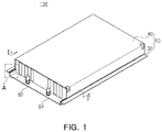
- FIG. 1 is a perspective view schematically showing a battery module according to an exemplary embodiment
- FIG. 2 is an exploded perspective view of the battery module illustrated in FIG. 1
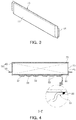
- FIG. 3 is a perspective view of a battery cell illustrated in FIG. 2
- FIG. 4 is a cross-sectional view taken along line I-I' of FIG. 1 .
- a battery module 100 each have a substantially hexahedral shape, and may include a cell assembly 20 and a case 50 protecting the cell assembly 20 from the outside.
- the cell assembly 20 includes a plurality of battery cells 10.
- a plurality of battery cells may be disposed side by side, and may have a structure in which an electrode tab protrudes outward from the body.
- the battery cell 10 may be, for example, a pouch type secondary battery.
- the battery cell 10 may be configured to have a form in which an electrode assembly (not illustrated) is accommodated in a pouch 11 as illustrated in FIG. 3 .
- the electrode assembly includes a plurality of electrode plates and electrode tabs and is accommodated in the pouch 11.
- the electrode plate is comprised of a positive electrode plate and a negative electrode plate, and the electrode assembly may be configured to have a stacked form in such a manner that the positive electrode plate and the negative electrode plate are stacked so that wide surfaces face each other with a separator therebetween.
- the positive electrode plate and the negative electrode plate are formed in a structure in which an active material slurry is applied to a current collector, and the slurry may be formed by stirring a granular active material, an auxiliary conductor, a binder, and a plasticizer in a state in which a solvent is added.
- the electrode tab is respectively provided on the plurality of positive electrode plates and the plurality of negative electrode plates, and may be connected to the same electrode lead 15 by contacting each other with the same polarity.
- the pouch 11 is formed in a container shape to provide an inner space in which the electrode assembly and the electrolyte are accommodated. In this case, a portion of the electrode lead 15 of the electrode assembly is exposed outwardly of the pouch 11.
- the battery cell 10 configured as described above generates current as a nickel metal hydride (Ni-MH) battery or a lithium ion (Li-ion) battery capable of charging and discharging.
- the battery cells 10 are vertically erected in the case 50 to be described later, to be stacked in the left and right directions.
- the cell assembly 20 may include a bus bar electrically connecting the electrode leads 15 of the battery cells 10, a connection terminal 19 electrically connecting the battery cells 10 to an external device, and a voltage sensing unit sensing the voltage of the battery cells 10. Since the bus bar, the connection terminal 19, and the voltage sensing unit are well-known components, detailed descriptions thereof will be omitted.
- the case 50 defines the exterior of the battery module 100, and may accommodate the cell assembly 20 therein to protect the cell assembly 20 from the external environment.
- the case 50 of this embodiment also functions as a cooling member of the battery module 100.
- the case 50 may include a first case 30 coupled to a lower portion of the cell assembly 20 and a second case 40 coupled to an upper portion of the cell assembly 20.
- At least one of the first case 30 and the second case 40 functions as a cooling member of the battery module 100.
- the first case 30 may function as a cooling member, but the configuration of the present disclosure is not limited thereto.
- the second case 40 may also be configured to function as a cooling member having the same shape as the first case 30.
- the first case 30 may include a lower plate 31 disposed below the cell assembly 20 to support lower surfaces of the battery cells 10, and at least one or more first side plates 35 supporting the side of the cell assembly 20.
- the lower plate 31 and the first side plate 35 may be configured by pressing a metal plate. Therefore, the lower plate 31 and the first side plate 35 may be integrally formed, but the configuration of the embodiment is not limited thereto.
- the first side plate 35 and the lower plate 31 may also be configured as independent elements, as required.
- the lower plate 31 supports the lower surfaces of the battery cells 10, and simultaneously, may cool the battery cells 10.
- the first side plates 35 may be formed to extend from both sides of the lower plate 31, and may be disposed on the sides of the cell assembly 20 disposed therein.
- the first side plate 35 may be configured in such a manner that the inner side contacts the cell assembly 20, but the embodiment is not limited thereto.
- various modifications may be applied as required, such as interposing a heat dissipation pad or a buffer member between the first side plate 35 and the cell assembly 20.
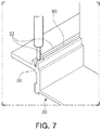
- FIG. 7 is an enlarged view of portion A of FIG. 1 , and referring to FIG. 7 together, the lower plate 31 may include an insertion groove 39.
- the insertion groove 39 is a groove disposed outside of a region in which the cell assembly 20 is disposed, and a second side plate 45 of the second case 40 may be inserted into the insertion groove 39 when the second case 40 and the first case 30 are coupled. Therefore, the insertion groove 39 may be disposed in a position corresponding to a lower end of the second side plate 45 and may be formed as a linear groove.
- the insertion groove 39 may be formed between two linear guides 33 protruding from the upper surface of the lower plate 31, but the embodiment is not limited thereto.
- various modifications may be applied, such as omitting a linear guide and forming an insertion groove as a groove having a concave shape that is concave into a lower portion of the lower plate 31.
- the lower plate 31 includes an inner plate 37 and an outer plate 38.
- FIG. 5 is a bottom view of the battery module illustrated in FIG. 1
- FIG. 6 is an exploded perspective view of the first case illustrated in FIG. 1 .
- the inner plate 37 is a plate disposed on the cell assembly 20 side
- the outer plate 38 is a plate disposed outside of the inner plate 37 and coupled to an external surface of the inner plate 37.
- the inner plate 37 is integrally formed with the first side plate 35 described above. Therefore, the inner plate 37 and the first side plate 35 may be configured by pressing one metal plate.
- the outer plate 38 is joined to the lower surface, which is the external surface of the inner plate 37.
- the entirety of the outer plate 38 is not joined but only partially joined, and at least a portion of the unbonded part may be spaced apart from the inner plate 37.
- the space between the inner plate 37 and the outer plate 38 formed thereby may be used as a cooling passage 36.
- the lower plate 31 of this embodiment may include a first joining portion S1 formed along an edge of the outer plate 38 and a second joining portion S2 disposed inside the outer plate 38.
- the first joining portion S1 may be formed on the entirety of the edge of the outer plate 38. Therefore, the entire edge of the outer plate 38 may be bonded to the inner plate 37. The first joining portion S1 may be bonded to the inner plate 37 through welding.
- a joining member 80 may be disposed between the first joining portion S1 and the inner plate 37 along the edge of the outer plate 38 to join the outer plate 38 and the inner plate 37 to each other.
- the joining member 80 may be formed by welding.
- the second joining portion S2 is a portion that is joined to the inner plate 37 inside the outer plate 38, and may be provided as one or a plurality, as required.
- the second joining portion S2 may be spaced apart from the first joining portion S1 and may be disposed in one or a plurality of regions among the inner regions of the outer plate 38.
- Areas other than the first joining portion S1 and the second joining portion S2 in the outer plate 38 may be used as the cooling passage 36. To this end, at least a portion of the outer plate 38 in these areas may be spaced apart from the inner plate 37 by a predetermined distance, and thus, a spacing space formed accordingly may be used as the cooling passage 36.
- the second joining portion S2 may be used to configure the shape and path of the cooling passage 36.
- the second joining portion S2 may be disposed to branch the cooling passage 36 into a plurality of pieces or to change the direction of the cooling passage 36.
- the second joining portion S2 may be formed in a linear or dot shape, but the shape is not limited thereto.
- the cooling passage 36 is entirely disposed inside the outer plate 38.
- the cooling passage 36 may be configured to be branched into three by the second joining portion S2.
- the shape of the cooling passage 36 may be modified to have various forms as required.
- the second joining portion S2 may be joined to the inner plate 37 through welding.
- friction stir welding FSW
- the embodiment is not limited thereto.
- the outer plate 38 configured as described above, may be manufactured by pressing a metal plate.
- one side of the inner plate 37 may be provided with an inlet 62 and an outlet 64 of the cooling passage 36. Therefore, the cooling water may be introduced into the cooling passage 36 described above, through the inlet 62, may pass through the cooling passage 36, and may then be discharged to the outside of the cooling passage 36 through the outlet 64.
- the configuration of the embodiment is not limited thereto and may be modified variously.
- the outlet 64 and the inlet 62 may be disposed on the outer plate 38 or may be distributedly disposed on the outer plate 38 and the inner plate 37, respectively.
- the first case 30 configured as described above may be formed of a material having high thermal conductivity such as metal.
- the first case 30 may be formed of aluminum, but the material is not limited thereto. Therefore, various materials may be used as long as the material has similar strength and thermal conductivity even if the material is not a metal.
- the inner plate 37 and the outer plate 38 may be formed of the same material, for example, aluminum, but the material is not limited thereto.
- the inner plate 37 and the outer plate 38 may also be formed of different materials.
- the second case 40 includes an upper plate 42 and at least one second side plate 45, disposed on an upper portion of the battery cell 10.
- the upper plate 42 is coupled to an upper surface of the cell assembly 20, and the second side plate 45 may be disposed on a side of the cell assembly 20, on which the first side plate 35 is not disposed, from among sides of the cell assembly 20.
- the first side plate 35 is disposed on two opposite sides of four sides of the cell assembly 20, and the second side plate 45 is disposed on the other two opposite sides.
- the second side plate 45 may be omitted.
- the first side plate 35 may be omitted.
- the upper plate 42 is formed integrally with the second side plate 45. Therefore, the upper plate 42 and the second side plate 45 may be configured by pressing one metal plate.
- the upper plate 42 is formed to have a flat plate shape, and may include through-holes 47 disposed with connection terminals 19, to expose the connection terminals 19 provided in the cell assembly 20 to the outside of the case 50.
- the lower end of the second side plate 45 is inserted into the insertion groove 39 formed in the first case 30. Therefore, the lower end of the second side plate 45 may be configured to be disposed in a position corresponding to the insertion groove 39.
- the second case 40 is formed of a material having relatively high thermal conductivity, such as metal.
- the second case 40 may be formed of aluminum.
- the embodiments are not limited thereto, and various materials may be used as long as the material has similar strength and thermal conductivity, even if the material is not a metal.
- the first case 30 and the second case 40 may be combined by welding or the like.
- the second case 40 is coupled to the first case 30 to primarily bond the first case 30 and the second case 40 to each other, and then, to ultimately join the first case 30 and the second case by welding contact portions (for example, an upper end of the linear guide) of the first case 30 and the second case 40.
- the embodiment is not limited thereto, and various modifications may be applied, such as combining by a sliding method, using a fixing member such as a bolt or a screw, or the combination thereof.
- a heat transfer member 60 may be disposed between the cell assembly 20 and the first case 30.
- the heat transfer member 60 may be formed of a material having relatively high thermal conductivity, for example, epoxy, urethane, silicone, acrylic resin, etc., but the material is not limited thereto.
- the heat transfer member 60 may be formed by applying a liquid or gel material to the lower plate 31 and curing the same. Accordingly, the heat transfer member 60 may be disposed in a form filling the space between the cell assembly 20 and the first case 30.
- the cell assembly 20 may be securely fixed to the case 50 in the interior space of the case 50, and heat emitted from the cell assembly 20 is passed through the heat transfer member 60, and may be quickly transferred to the second case 40. Also, as the heat transfer member 60 is disposed between the cell assembly 20 and the case 50, the overall rigidity of the battery module 100 may also be reinforced.
- a material of the heat transfer member 60 in this embodiment a material having relatively high insulating properties, for example, a dielectric strength in the range of 10 to 30 KV/mm, may be used. Accordingly, in the battery module 100 according to this embodiment, even in a case in which the insulation is partially destroyed in the battery cell 10, the insulation between the cell assembly 20 and the case 50 may be maintained by the heat transfer member 60 disposed between the case 50 and the cell assembly 20.
- this embodiment since the thickness of the cell assembly 20 is not thick, heat may be radiated through the cooling passage 36 provided in the first case 30. Accordingly, this embodiment only provides a case in which the heat transfer member 60 is disposed between the cell assembly 20 and the lower plate 31 of the first case 30, as an example.
- the configuration of the present disclosure is not limited thereto.
- a cooling passage may also be provided in the second case 40, and in this case, the heat transfer member 60 may also be disposed between the cell assembly 20 and the second case 20.
- An insulating cover 70 may be disposed between the cell assembly 20 and the second case 40.
- the insulating cover 70 is formed of an insulating material to maintain insulation between the cell assembly 20 and the second case 40. Therefore, the insulating cover 70 is configured to cover the entire upper surface of the cell assembly 20, and may also be configured to partially cover a side surface of the cell assembly 20 as required.
- the insulating cover 70 may be omitted.
- the first case 30 supporting the lower surface of the cell assembly 20 may include the cooling passage 36. Therefore, since the cell assembly 20 and the cooling passage 36 are disposed as closely as possible, the cooling efficiency of the cell assembly 20 may be increased.
- cooling passage 36 is provided in the case 50 of the battery module 100, a separate cooling device does not need to be provided in the installation where the battery module 100 is mounted.
- the heat transfer member 60 fills the space between the cell assembly 20 and the case 50, the cell assembly 20 is firmly fixed to the case 50, thereby preventing the battery cell 10 from shaking due to external vibrations or shocks.
- first joining portion S1 disposed along the edge of the outer plate 38 is joined to the inner plate 37 through CMT welding forming the joining member 80, and the second bonding portion S2 disposed inside the outer plate 38 may be bonded to the inner plate 37 through friction stir welding (FSW). Therefore, the joining member 80 is formed between the first joining portion S1 and the inner plate 37 to tightly seal between the edge of the outer plate 38 and the inner plate 37. Accordingly, the cooling water may be prevented from flowing out between the outer plate 38 and the inner plate 37.
- FSW friction stir welding
- the second case 40 is inserted into the insertion groove 39 formed in the first case 30, such that the first case 30 and the second case 40 may be coupled to each other. Therefore, combining the first case 30 and the second case 40 may be facilitated, and thus, the manufacturing thereof is relatively easy.
- first and second cases 40 are combined using the liquid adhesive 90 and welding together, a more robust case 50 may be provided.
- a first case supporting the lower surface of a cell assembly includes a cooling passage. Therefore, since the cell assembly and the cooling passage are disposed as closely as possible, the cooling efficiency of the cell assembly may be increased.
Landscapes
- Chemical & Material Sciences (AREA)
- Chemical Kinetics & Catalysis (AREA)
- Electrochemistry (AREA)
- General Chemical & Material Sciences (AREA)
- Engineering & Computer Science (AREA)
- Manufacturing & Machinery (AREA)
- Secondary Cells (AREA)
- Battery Mounting, Suspending (AREA)
Abstract
Description
- This application claims the benefit under 35 USC 119(a) of Korean Patent Application No.
10-2019-0062049 filed on May 27, 2019 - The present disclosure relates to a battery module.
- Secondary batteries, unlike primary batteries, may be charged and discharged, and thus, may be applied to devices within various fields, such as digital cameras, cellphones, laptops, and hybrid vehicles. Examples of the secondary battery include a nickel-cadmium battery, a nickel-metal hydride battery, a nickel-hydrogen battery, a lithium secondary battery and the like.
- Among these secondary batteries, many studies are being conducted into lithium secondary batteries having high energy density and discharge voltages. Recently, lithium secondary batteries have been manufactured as pouch-type battery cells with flexibility to be configured and used in the form of a module through the connection of a plurality of pieces.
- However, in the related art case, a cooling device for cooling a battery module is configured separately from the battery module, and there may be a problem in that cooling loss may occur.
- An aspect of the present disclosure is to provide a battery module in which the cooling performance of a battery cell may be increased.
- According to an aspect of the present disclosure, a battery module includes a cell assembly in which a plurality of battery cells are stacked, and a lower plate, having a cooling passage and disposed below the cell assembly. The lower plate includes an inner plate disposed below the cell assembly, an outer plate, disposed outside of the inner plate and bonded to the inner plate, a first joining portion disposed along an edge of the outer plate to bond the outer plate to the inner plate, and a second joining portion disposed inside the outer plate to bond the outer plate to the inner plate.
- The battery module may further include a first case including the lower plate and a second case disposed on an upper portion of the cell assembly and coupled to the first case. The first case may have an insertion groove into which a lower end of the second case is inserted.
- The second case may include an upper plate disposed on an upper portion of the cell assembly, and at least one second side plate extending from the upper plate and disposed on a side of the cell assembly. A lower end of the second side plate may be inserted into the insertion groove.
- The cooling passage may be disposed between the inner plate and the outer plate.
- The battery module may further include an inlet and an outlet fastened to the inner plate and used as passages for cooling water to move to the cooling passage.
- The first joining portion may further include a joining member disposed along an edge of the outer plate to join the outer plate to the inner plate.
- The first joining portion may be provided by cold metal transfer (CMT) welding.
- The second joining portion may be spaced apart from the first joining portion.
- The second joining portion may be provided by friction stir welding (FSW).
- The inner plate and the outer plate may be formed of the same material.
- The above and other aspects, features, and advantages of the present disclosure will be more clearly understood from the following detailed description, taken in conjunction with the accompanying drawings, in which:
-
FIG. 1 is a perspective view schematically illustrating a battery module according to an exemplary embodiment; -
FIG. 2 is an exploded perspective view of the battery module illustrated inFIG. 1 ; -
FIG. 3 is a perspective view of a battery cell illustrated inFIG. 2 ; -
FIG. 4 is a cross-sectional view taken along line I-I' ofFIG. 1 ; -
FIG. 5 is a bottom view of the battery module illustrated inFIG. 1 ; -
FIG. 6 is an exploded perspective view of a first case illustrated inFIG. 1 ; and -
FIG. 7 is an enlarged view of portion A ofFIG. 1 . - The following detailed description is provided to assist the reader in gaining a comprehensive understanding of the methods, apparatuses, and/or systems described herein. However, various changes, modifications, and equivalents of the methods, apparatuses, and/or systems described herein will be apparent to one of ordinary skill in the art. The sequences of operations described herein are merely examples, and are not limited to those set forth herein, but may be changed as will be apparent to one of ordinary skill in the art, with the exception of operations necessarily occurring in a certain order. Also, descriptions of functions and constructions that would be well known to one of ordinary skill in the art may be omitted for increased clarity and conciseness.
- The features described herein may be embodied in different forms, and are not to be construed as being limited to the examples described herein. Rather, the examples described herein have been provided so that this disclosure will be thorough and complete, and will fully convey the scope of the disclosure to one of ordinary skill in the art.
- Herein, it is noted that use of the term "may" with respect to an example or embodiment, e.g., as to what an example or embodiment may include or implement, means that at least one example or embodiment exists in which such a feature is included or implemented while all examples and embodiments are not limited thereto.
- Throughout the specification, when an element, such as a layer, region, or substrate, is described as being "on," "connected to," or "coupled to" another element, it may be directly "on," "connected to," or "coupled to" the other element, or there may be one or more other elements intervening therebetween. In contrast, when an element is described as being "directly on," "directly connected to," or "directly coupled to" another element, there may be no other elements intervening therebetween.
- As used herein, the term "and/or" includes any one and any combination of any two or more of the associated listed items.
- Although terms such as "first," "second," and "third" may be used herein to describe various members, components, regions, layers, or sections, these members, components, regions, layers, or sections are not to be limited by these terms. Rather, these terms are only used to distinguish one member, component, region, layer, or section from another member, component, region, layer, or section. Thus, a first member, component, region, layer, or section referred to in examples described herein may also be referred to as a second member, component, region, layer, or section without departing from the teachings of the examples.
- Spatially relative terms such as "above," "upper," "below," and "lower" may be used herein for ease of description to describe one element's relationship to another element as illustrated in the figures. Such spatially relative terms are intended to encompass different orientations of the device in use or operation in addition to the orientation depicted in the figures. For example, if the device in the figures is turned over, an element described as being "above" or "upper" relative to another element will then be "below" or "lower" relative to the other element. Thus, the term "above" encompasses both the above and below orientations depending on the spatial orientation of the device. The device may also be oriented in other ways (for example, rotated 90 degrees or at other orientations), and the spatially relative terms used herein are to be interpreted accordingly.
- The terminology used herein is for describing various examples only, and is not to be used to limit the disclosure. The articles "a," "an," and "the" are intended to include the plural forms as well, unless the context clearly indicates otherwise. The terms "comprises," "includes," and "has" specify the presence of stated features, numbers, operations, members, elements, and/or combinations thereof, but do not preclude the presence or addition of one or more other features, numbers, operations, members, elements, and/or combinations thereof.
- Due to manufacturing techniques and/or tolerances, variations of the shapes illustrated in the drawings may occur. Thus, the examples described herein are not limited to the specific shapes illustrated in the drawings, but include changes in shape that occur during manufacturing.
- The features of the examples described herein may be combined in various ways as will be apparent after an understanding of the disclosure of this application. Further, although the examples described herein have a variety of configurations, other configurations are possible as will be apparent after an understanding of the disclosure of this application.
- The drawings may not be to scale, and the relative size, proportions, and depiction of elements in the drawings may be exaggerated for clarity, illustration, and convenience.
-
FIG. 1 is a perspective view schematically showing a battery module according to an exemplary embodiment, andFIG. 2 is an exploded perspective view of the battery module illustrated inFIG. 1 .FIG. 3 is a perspective view of a battery cell illustrated inFIG. 2 , andFIG. 4 is a cross-sectional view taken along line I-I' ofFIG. 1 . - Referring to
FIGS. 1 to 4 , abattery module 100 according to an exemplary embodiment each have a substantially hexahedral shape, and may include acell assembly 20 and acase 50 protecting thecell assembly 20 from the outside. - The
cell assembly 20 includes a plurality ofbattery cells 10. - In the case of the
battery cell 10, a plurality of battery cells may be disposed side by side, and may have a structure in which an electrode tab protrudes outward from the body. Thebattery cell 10 may be, for example, a pouch type secondary battery. - The
battery cell 10 may be configured to have a form in which an electrode assembly (not illustrated) is accommodated in apouch 11 as illustrated inFIG. 3 . The electrode assembly includes a plurality of electrode plates and electrode tabs and is accommodated in thepouch 11. In this case, the electrode plate is comprised of a positive electrode plate and a negative electrode plate, and the electrode assembly may be configured to have a stacked form in such a manner that the positive electrode plate and the negative electrode plate are stacked so that wide surfaces face each other with a separator therebetween. - The positive electrode plate and the negative electrode plate are formed in a structure in which an active material slurry is applied to a current collector, and the slurry may be formed by stirring a granular active material, an auxiliary conductor, a binder, and a plasticizer in a state in which a solvent is added.
- In addition, in the electrode assembly, a plurality of positive electrode plates and a plurality of negative electrode plates are stacked in a vertical direction. In this case, the electrode tab is respectively provided on the plurality of positive electrode plates and the plurality of negative electrode plates, and may be connected to the
same electrode lead 15 by contacting each other with the same polarity. - The
pouch 11 is formed in a container shape to provide an inner space in which the electrode assembly and the electrolyte are accommodated. In this case, a portion of theelectrode lead 15 of the electrode assembly is exposed outwardly of thepouch 11. - The
battery cell 10 configured as described above generates current as a nickel metal hydride (Ni-MH) battery or a lithium ion (Li-ion) battery capable of charging and discharging. In addition, thebattery cells 10 are vertically erected in thecase 50 to be described later, to be stacked in the left and right directions. - In addition, the
cell assembly 20 may include a bus bar electrically connecting the electrode leads 15 of thebattery cells 10, aconnection terminal 19 electrically connecting thebattery cells 10 to an external device, and a voltage sensing unit sensing the voltage of thebattery cells 10. Since the bus bar, theconnection terminal 19, and the voltage sensing unit are well-known components, detailed descriptions thereof will be omitted. - The
case 50 defines the exterior of thebattery module 100, and may accommodate thecell assembly 20 therein to protect thecell assembly 20 from the external environment. In addition, thecase 50 of this embodiment also functions as a cooling member of thebattery module 100. - The
case 50 according to the exemplary embodiment may include afirst case 30 coupled to a lower portion of thecell assembly 20 and asecond case 40 coupled to an upper portion of thecell assembly 20. - At least one of the
first case 30 and thesecond case 40 functions as a cooling member of thebattery module 100. In the case of this embodiment, thefirst case 30 may function as a cooling member, but the configuration of the present disclosure is not limited thereto. For example, in the case in which the height of thebattery cell 10 is relatively great, thesecond case 40 may also be configured to function as a cooling member having the same shape as thefirst case 30. - The
first case 30 may include alower plate 31 disposed below thecell assembly 20 to support lower surfaces of thebattery cells 10, and at least one or morefirst side plates 35 supporting the side of thecell assembly 20. Thelower plate 31 and thefirst side plate 35 may be configured by pressing a metal plate. Therefore, thelower plate 31 and thefirst side plate 35 may be integrally formed, but the configuration of the embodiment is not limited thereto. For example, thefirst side plate 35 and thelower plate 31 may also be configured as independent elements, as required. - The
lower plate 31 supports the lower surfaces of thebattery cells 10, and simultaneously, may cool thebattery cells 10. - The
first side plates 35 may be formed to extend from both sides of thelower plate 31, and may be disposed on the sides of thecell assembly 20 disposed therein. - To firmly support the
cell assembly 20, thefirst side plate 35 may be configured in such a manner that the inner side contacts thecell assembly 20, but the embodiment is not limited thereto. For example, various modifications may be applied as required, such as interposing a heat dissipation pad or a buffer member between thefirst side plate 35 and thecell assembly 20. -
FIG. 7 is an enlarged view of portion A ofFIG. 1 , and referring toFIG. 7 together, thelower plate 31 may include aninsertion groove 39. Theinsertion groove 39 is a groove disposed outside of a region in which thecell assembly 20 is disposed, and asecond side plate 45 of thesecond case 40 may be inserted into theinsertion groove 39 when thesecond case 40 and thefirst case 30 are coupled. Therefore, theinsertion groove 39 may be disposed in a position corresponding to a lower end of thesecond side plate 45 and may be formed as a linear groove. - In this embodiment, the
insertion groove 39 may be formed between two linear guides 33 protruding from the upper surface of thelower plate 31, but the embodiment is not limited thereto. For example, various modifications may be applied, such as omitting a linear guide and forming an insertion groove as a groove having a concave shape that is concave into a lower portion of thelower plate 31. - In addition, the
lower plate 31 according to this embodiment includes aninner plate 37 and anouter plate 38. -
FIG. 5 is a bottom view of the battery module illustrated inFIG. 1 , andFIG. 6 is an exploded perspective view of the first case illustrated inFIG. 1 . - Referring to
FIGS. 5 and6 together, theinner plate 37 is a plate disposed on thecell assembly 20 side, and theouter plate 38 is a plate disposed outside of theinner plate 37 and coupled to an external surface of theinner plate 37. - The
inner plate 37 is integrally formed with thefirst side plate 35 described above. Therefore, theinner plate 37 and thefirst side plate 35 may be configured by pressing one metal plate. - The
outer plate 38 is joined to the lower surface, which is the external surface of theinner plate 37. In this case, the entirety of theouter plate 38 is not joined but only partially joined, and at least a portion of the unbonded part may be spaced apart from theinner plate 37. The space between theinner plate 37 and theouter plate 38 formed thereby may be used as acooling passage 36. - To this end, the
lower plate 31 of this embodiment may include a first joining portion S1 formed along an edge of theouter plate 38 and a second joining portion S2 disposed inside theouter plate 38. - The first joining portion S1 may be formed on the entirety of the edge of the
outer plate 38. Therefore, the entire edge of theouter plate 38 may be bonded to theinner plate 37. The first joining portion S1 may be bonded to theinner plate 37 through welding. - Cold Metal Transfer (CMT) welding may be used to bond the first joining portion S1. Accordingly, a joining
member 80 may be disposed between the first joining portion S1 and theinner plate 37 along the edge of theouter plate 38 to join theouter plate 38 and theinner plate 37 to each other. The joiningmember 80 may be formed by welding. - The second joining portion S2 is a portion that is joined to the
inner plate 37 inside theouter plate 38, and may be provided as one or a plurality, as required. The second joining portion S2 may be spaced apart from the first joining portion S1 and may be disposed in one or a plurality of regions among the inner regions of theouter plate 38. - Areas other than the first joining portion S1 and the second joining portion S2 in the
outer plate 38 may be used as thecooling passage 36. To this end, at least a portion of theouter plate 38 in these areas may be spaced apart from theinner plate 37 by a predetermined distance, and thus, a spacing space formed accordingly may be used as thecooling passage 36. - The second joining portion S2 may be used to configure the shape and path of the
cooling passage 36. For example, the second joining portion S2 may be disposed to branch thecooling passage 36 into a plurality of pieces or to change the direction of thecooling passage 36. The second joining portion S2 may be formed in a linear or dot shape, but the shape is not limited thereto. - The
cooling passage 36 is entirely disposed inside theouter plate 38. In this embodiment, thecooling passage 36 may be configured to be branched into three by the second joining portion S2. However, the shape of thecooling passage 36 may be modified to have various forms as required. - The second joining portion S2 may be joined to the
inner plate 37 through welding. In the case of the second joining portion S2, since welding should be performed through the external surface of theouter plate 38, friction stir welding (FSW) may be used for joining the second joining portion S2. However, the embodiment is not limited thereto. - The
outer plate 38, configured as described above, may be manufactured by pressing a metal plate. - On the other hand, in this embodiment, one side of the
inner plate 37 may be provided with aninlet 62 and anoutlet 64 of thecooling passage 36. Therefore, the cooling water may be introduced into thecooling passage 36 described above, through theinlet 62, may pass through thecooling passage 36, and may then be discharged to the outside of thecooling passage 36 through theoutlet 64. However, the configuration of the embodiment is not limited thereto and may be modified variously. For example, if necessary, theoutlet 64 and theinlet 62 may be disposed on theouter plate 38 or may be distributedly disposed on theouter plate 38 and theinner plate 37, respectively. - The
first case 30 configured as described above may be formed of a material having high thermal conductivity such as metal. For example, thefirst case 30 may be formed of aluminum, but the material is not limited thereto. Therefore, various materials may be used as long as the material has similar strength and thermal conductivity even if the material is not a metal. - In this embodiment, the
inner plate 37 and theouter plate 38 may be formed of the same material, for example, aluminum, but the material is not limited thereto. For example, theinner plate 37 and theouter plate 38 may also be formed of different materials. - The
second case 40 includes an upper plate 42 and at least onesecond side plate 45, disposed on an upper portion of thebattery cell 10. - The upper plate 42 is coupled to an upper surface of the
cell assembly 20, and thesecond side plate 45 may be disposed on a side of thecell assembly 20, on which thefirst side plate 35 is not disposed, from among sides of thecell assembly 20. - In this embodiment, the
first side plate 35 is disposed on two opposite sides of four sides of thecell assembly 20, and thesecond side plate 45 is disposed on the other two opposite sides. On the other hand, in a case in which thefirst side plate 35 is disposed on all four sides of thecell assembly 20, thesecond side plate 45 may be omitted. Similarly, in a case in which thesecond side plate 45 is disposed on all four sides of thecell assembly 20, thefirst side plate 35 may be omitted. - The upper plate 42 is formed integrally with the
second side plate 45. Therefore, the upper plate 42 and thesecond side plate 45 may be configured by pressing one metal plate. - The upper plate 42 is formed to have a flat plate shape, and may include through-
holes 47 disposed withconnection terminals 19, to expose theconnection terminals 19 provided in thecell assembly 20 to the outside of thecase 50. - On the other hand, when the
second case 40 and thefirst case 30 are combined, the lower end of thesecond side plate 45 is inserted into theinsertion groove 39 formed in thefirst case 30. Therefore, the lower end of thesecond side plate 45 may be configured to be disposed in a position corresponding to theinsertion groove 39. - Similarly to the
first case 30, thesecond case 40 is formed of a material having relatively high thermal conductivity, such as metal. Thesecond case 40 may be formed of aluminum. However, the embodiments are not limited thereto, and various materials may be used as long as the material has similar strength and thermal conductivity, even if the material is not a metal. - The
first case 30 and thesecond case 40 may be combined by welding or the like. - For example, as illustrated in
FIG. 7 , after applying a liquid adhesive 90 to theinsertion groove 39, thesecond case 40 is coupled to thefirst case 30 to primarily bond thefirst case 30 and thesecond case 40 to each other, and then, to ultimately join thefirst case 30 and the second case by welding contact portions (for example, an upper end of the linear guide) of thefirst case 30 and thesecond case 40. - However, the embodiment is not limited thereto, and various modifications may be applied, such as combining by a sliding method, using a fixing member such as a bolt or a screw, or the combination thereof.
- A
heat transfer member 60 may be disposed between thecell assembly 20 and thefirst case 30. Theheat transfer member 60 may be formed of a material having relatively high thermal conductivity, for example, epoxy, urethane, silicone, acrylic resin, etc., but the material is not limited thereto. - The
heat transfer member 60 may be formed by applying a liquid or gel material to thelower plate 31 and curing the same. Accordingly, theheat transfer member 60 may be disposed in a form filling the space between thecell assembly 20 and thefirst case 30. - By the
heat transfer member 60, thecell assembly 20 may be securely fixed to thecase 50 in the interior space of thecase 50, and heat emitted from thecell assembly 20 is passed through theheat transfer member 60, and may be quickly transferred to thesecond case 40. Also, as theheat transfer member 60 is disposed between thecell assembly 20 and thecase 50, the overall rigidity of thebattery module 100 may also be reinforced. - As a material of the
heat transfer member 60 in this embodiment, a material having relatively high insulating properties, for example, a dielectric strength in the range of 10 to 30 KV/mm, may be used. Accordingly, in thebattery module 100 according to this embodiment, even in a case in which the insulation is partially destroyed in thebattery cell 10, the insulation between thecell assembly 20 and thecase 50 may be maintained by theheat transfer member 60 disposed between thecase 50 and thecell assembly 20. - On the other hand, in this embodiment, since the thickness of the
cell assembly 20 is not thick, heat may be radiated through thecooling passage 36 provided in thefirst case 30. Accordingly, this embodiment only provides a case in which theheat transfer member 60 is disposed between thecell assembly 20 and thelower plate 31 of thefirst case 30, as an example. However, the configuration of the present disclosure is not limited thereto. For example, in a case in which the thickness of thecell assembly 20 relatively increases, a cooling passage may also be provided in thesecond case 40, and in this case, theheat transfer member 60 may also be disposed between thecell assembly 20 and thesecond case 20. - An insulating
cover 70 may be disposed between thecell assembly 20 and thesecond case 40. The insulatingcover 70 is formed of an insulating material to maintain insulation between thecell assembly 20 and thesecond case 40. Therefore, the insulatingcover 70 is configured to cover the entire upper surface of thecell assembly 20, and may also be configured to partially cover a side surface of thecell assembly 20 as required. - As described above, in the case in which the heat transfer member is also disposed between the
cell assembly 20 and thesecond case 40, the insulatingcover 70 may be omitted. - In the
battery module 100 according to this embodiment configured as described above, thefirst case 30 supporting the lower surface of thecell assembly 20 may include thecooling passage 36. Therefore, since thecell assembly 20 and thecooling passage 36 are disposed as closely as possible, the cooling efficiency of thecell assembly 20 may be increased. - In addition, since the
cooling passage 36 is provided in thecase 50 of thebattery module 100, a separate cooling device does not need to be provided in the installation where thebattery module 100 is mounted. - In addition, since the
heat transfer member 60 fills the space between thecell assembly 20 and thecase 50, thecell assembly 20 is firmly fixed to thecase 50, thereby preventing thebattery cell 10 from shaking due to external vibrations or shocks. - In addition, the first joining portion S1 disposed along the edge of the
outer plate 38 is joined to theinner plate 37 through CMT welding forming the joiningmember 80, and the second bonding portion S2 disposed inside theouter plate 38 may be bonded to theinner plate 37 through friction stir welding (FSW). Therefore, the joiningmember 80 is formed between the first joining portion S1 and theinner plate 37 to tightly seal between the edge of theouter plate 38 and theinner plate 37. Accordingly, the cooling water may be prevented from flowing out between theouter plate 38 and theinner plate 37. - In addition, the
second case 40 is inserted into theinsertion groove 39 formed in thefirst case 30, such that thefirst case 30 and thesecond case 40 may be coupled to each other. Therefore, combining thefirst case 30 and thesecond case 40 may be facilitated, and thus, the manufacturing thereof is relatively easy. - In addition, since the first and
second cases 40 are combined using theliquid adhesive 90 and welding together, a morerobust case 50 may be provided. - As set forth above, in a battery module according to an exemplary embodiment, a first case supporting the lower surface of a cell assembly includes a cooling passage. Therefore, since the cell assembly and the cooling passage are disposed as closely as possible, the cooling efficiency of the cell assembly may be increased.
- While this disclosure includes specific examples, it will be apparent to one of ordinary skill in the art that various changes in form and details may be made in these examples without departing from the spirit and scope of the claims and their equivalents. The examples described herein are to be considered in a descriptive sense only, and not for purposes of limitation. Descriptions of features or aspects in each example are to be considered as being applicable to similar features or aspects in other examples. Suitable results may be achieved if the described techniques are performed to have a different order, and/or if components in a described system, architecture, device, or circuit are combined in a different manner, and/or replaced or supplemented by other components or their equivalents. Therefore, the scope of the disclosure is defined not by the detailed description, but by the claims and their equivalents, and all variations within the scope of the claims and their equivalents are to be construed as being included in the disclosure.
Claims (10)
- A battery module comprising:a cell assembly in which a plurality of battery cells are stacked; anda lower plate, having a cooling passage and disposed below the cell assembly,wherein the lower plate includes:an inner plate disposed below the cell assembly;an outer plate, disposed outside of the inner plate and bonded to the inner plate;a first joining portion disposed along an edge of the outer plate to bond the outer plate to the inner plate; anda second joining portion disposed inside the outer plate to bond the outer plate to the inner plate.
- The battery module of claim 1, further comprising a first case including the lower plate and a second case disposed on an upper portion of the cell assembly and coupled to the first case,
wherein the first case has an insertion groove into which a lower end of the second case is inserted. - The battery module of claim 2, wherein the second case comprises an upper plate disposed on an upper portion of the cell assembly, and at least one side plate extending from the upper plate and disposed on a side of the cell assembly, and
a lower end of the side plate is inserted into the insertion groove. - The battery module of claim 1, wherein the cooling passage is disposed between the inner plate and the outer plate.
- The battery module of claim 4, further comprising an inlet and an outlet fastened to the inner plate and used as passages for cooling water to move to the cooling passage.
- The battery module of claim 1, wherein the first joining portion further comprises a joining member disposed along an edge of the outer plate to join the outer plate to the inner plate.
- The battery module of claim 1, wherein the first joining portion is provided by cold metal transfer (CMT) welding.
- The battery module of claim 1, wherein the second joining portion is spaced apart from the first joining portion.
- The battery module of claim 1, wherein the second joining portion is provided by friction stir welding (FSW).
- The battery module of claim 1, wherein the inner plate and the outer plate are formed of the same material.
Applications Claiming Priority (1)
| Application Number | Priority Date | Filing Date | Title |
|---|---|---|---|
| KR1020190062049A KR20200136229A (en) | 2019-05-27 | 2019-05-27 | Bettery module |
Publications (1)
| Publication Number | Publication Date |
|---|---|
| EP3748723A1 true EP3748723A1 (en) | 2020-12-09 |
Family
ID=70861235
Family Applications (1)
| Application Number | Title | Priority Date | Filing Date |
|---|---|---|---|
| EP20176669.8A Pending EP3748723A1 (en) | 2019-05-27 | 2020-05-26 | Battery module |
Country Status (4)
| Country | Link |
|---|---|
| US (1) | US20200381790A1 (en) |
| EP (1) | EP3748723A1 (en) |
| KR (1) | KR20200136229A (en) |
| CN (1) | CN112002841A (en) |
Families Citing this family (4)
| Publication number | Priority date | Publication date | Assignee | Title |
|---|---|---|---|---|
| KR20200141157A (en) * | 2019-06-10 | 2020-12-18 | 현대자동차주식회사 | Cooling block for battery module and manufacturing method thereof |
| KR20220094028A (en) * | 2020-12-28 | 2022-07-05 | 현대모비스 주식회사 | Battery module cooling structure |
| KR20230007739A (en) * | 2021-07-06 | 2023-01-13 | 주식회사 엘지에너지솔루션 | Battery module and battery pack including the same |
| CN218867280U (en) * | 2022-10-28 | 2023-04-14 | 宁德时代新能源科技股份有限公司 | Battery, energy storage device and electric equipment |
Citations (3)
| Publication number | Priority date | Publication date | Assignee | Title |
|---|---|---|---|---|
| US20180138565A1 (en) * | 2015-09-24 | 2018-05-17 | Lg Chem, Ltd. | Battery module |
| WO2018131776A1 (en) * | 2017-01-12 | 2018-07-19 | 삼성에스디아이(주) | Battery pack housing and battery pack comprising same |
| EP3352291A1 (en) * | 2016-05-31 | 2018-07-25 | LG Chem, Ltd. | Battery module, battery pack comprising same, and automobile |
Family Cites Families (18)
| Publication number | Priority date | Publication date | Assignee | Title |
|---|---|---|---|---|
| US9077056B2 (en) * | 2007-12-11 | 2015-07-07 | Battery Patent Trust | Device for housing electrochemical cells |
| CN201408788Y (en) * | 2009-04-01 | 2010-02-17 | 神讯电脑(昆山)有限公司 | Water-proof battery case mechanism |
| JP2012248299A (en) * | 2011-05-25 | 2012-12-13 | Sanyo Electric Co Ltd | Battery module, battery system, electric vehicle, mobile object, power storage device and power supply device |
| US9985268B2 (en) * | 2013-09-06 | 2018-05-29 | Johnson Controls Technology Company | Battery module housing and method of making the same |
| US10388920B2 (en) * | 2014-08-26 | 2019-08-20 | Cps Technology Holdings Llc | Collar for sealing a battery module |
| DE102014225971A1 (en) * | 2014-12-16 | 2016-06-16 | Robert Bosch Gmbh | Cooling plate for battery cell as a mounting plate |
| KR102056875B1 (en) * | 2015-11-10 | 2019-12-17 | 주식회사 엘지화학 | Battery module and battery pack including the same |
| US11539087B2 (en) * | 2016-12-29 | 2022-12-27 | Faraday & Future Inc. | Vehicle energy-storage systems |
| CN206332080U (en) * | 2016-12-29 | 2017-07-14 | 芜湖天量电池系统有限公司 | A kind of shockproof welds window frame structure |
| KR101916429B1 (en) * | 2017-03-30 | 2018-11-07 | 엘지전자 주식회사 | Battery pack for vehicle and vehicle |
| CN207474522U (en) * | 2017-09-29 | 2018-06-08 | 凌云工业股份有限公司 | A kind of integrated water-cooling housing of power cell |
| CN107732061A (en) * | 2017-09-29 | 2018-02-23 | 凌云工业股份有限公司 | A kind of integrated water-cooling housing of power cell for new-energy automobile |
| KR102201332B1 (en) * | 2017-10-24 | 2021-01-08 | 주식회사 엘지화학 | Battery pack and vehicle comprising the same |
| DE102017127807B4 (en) * | 2017-11-24 | 2019-06-27 | Dr. Ing. H.C. F. Porsche Aktiengesellschaft | Battery device for an at least partially electrically operated motor vehicle |
| CN207883779U (en) * | 2018-03-13 | 2018-09-18 | 宁德时代新能源科技股份有限公司 | A kind of battery modules peripheral frame and its battery modules |
| CN208570859U (en) * | 2018-07-25 | 2019-03-01 | 杭州捷能科技有限公司 | A kind of battery system liquid cooling system |
| CN109066006A (en) * | 2018-07-25 | 2018-12-21 | 杭州捷能科技有限公司 | A kind of battery system liquid cooling system and its assembly method |
| CN108963137A (en) * | 2018-09-18 | 2018-12-07 | 崔晓迪 | A kind of dust-proof management box of battery and its application method |
-
2019
- 2019-05-27 KR KR1020190062049A patent/KR20200136229A/en active Search and Examination
-
2020
- 2020-05-26 EP EP20176669.8A patent/EP3748723A1/en active Pending
- 2020-05-27 US US16/884,175 patent/US20200381790A1/en not_active Abandoned
- 2020-05-27 CN CN202010463244.9A patent/CN112002841A/en active Pending
Patent Citations (4)
| Publication number | Priority date | Publication date | Assignee | Title |
|---|---|---|---|---|
| US20180138565A1 (en) * | 2015-09-24 | 2018-05-17 | Lg Chem, Ltd. | Battery module |
| EP3352291A1 (en) * | 2016-05-31 | 2018-07-25 | LG Chem, Ltd. | Battery module, battery pack comprising same, and automobile |
| WO2018131776A1 (en) * | 2017-01-12 | 2018-07-19 | 삼성에스디아이(주) | Battery pack housing and battery pack comprising same |
| US20190312322A1 (en) * | 2017-01-12 | 2019-10-10 | Samsung Sdi Co., Ltd. | Battery pack housing and battery pack comprising same |
Also Published As
| Publication number | Publication date |
|---|---|
| KR20200136229A (en) | 2020-12-07 |
| US20200381790A1 (en) | 2020-12-03 |
| CN112002841A (en) | 2020-11-27 |
Similar Documents
| Publication | Publication Date | Title |
|---|---|---|
| US11804626B2 (en) | Battery modules with improved heat dissipation | |
| US11862777B2 (en) | Battery module | |
| JP7047220B2 (en) | Battery module including rechargeable battery and bus bar | |
| EP3748723A1 (en) | Battery module | |
| US20220037722A1 (en) | Battery Cell and Battery Module Including the Same | |
| US11784360B2 (en) | Battery module | |
| US11973207B2 (en) | Cell unit for battery module | |
| CN111864132A (en) | Battery module | |
| EP3902054B1 (en) | Battery module | |
| KR102699572B1 (en) | Bettery module | |
| JP2023541159A (en) | Battery module and battery pack containing it | |
| JP7154652B2 (en) | Battery packs and devices containing them | |
| KR102632249B1 (en) | Bettery module | |
| KR102699573B1 (en) | Bettery module | |
| KR20210136710A (en) | Battery module | |
| KR20210011641A (en) | Battery module and battery pack including the same | |
| US20220209352A1 (en) | Battery module | |
| US12148906B2 (en) | Battery module | |
| EP4266465A1 (en) | Battery module | |
| EP4175018A1 (en) | Battery cell and battery module having the same | |
| CN117096418A (en) | Pouch-type battery cell, battery cell assembly provided with same, and battery pack |
Legal Events
| Date | Code | Title | Description |
|---|---|---|---|
| PUAI | Public reference made under article 153(3) epc to a published international application that has entered the european phase |
Free format text: ORIGINAL CODE: 0009012 |
|
| STAA | Information on the status of an ep patent application or granted ep patent |
Free format text: STATUS: THE APPLICATION HAS BEEN PUBLISHED |
|
| AK | Designated contracting states |
Kind code of ref document: A1 Designated state(s): AL AT BE BG CH CY CZ DE DK EE ES FI FR GB GR HR HU IE IS IT LI LT LU LV MC MK MT NL NO PL PT RO RS SE SI SK SM TR |
|
| AX | Request for extension of the european patent |
Extension state: BA ME |
|
| STAA | Information on the status of an ep patent application or granted ep patent |
Free format text: STATUS: REQUEST FOR EXAMINATION WAS MADE |
|
| 17P | Request for examination filed |
Effective date: 20210609 |
|
| RBV | Designated contracting states (corrected) |
Designated state(s): AL AT BE BG CH CY CZ DE DK EE ES FI FR GB GR HR HU IE IS IT LI LT LU LV MC MK MT NL NO PL PT RO RS SE SI SK SM TR |
|
| RAP1 | Party data changed (applicant data changed or rights of an application transferred) |
Owner name: SK ON CO., LTD. |
|
| P01 | Opt-out of the competence of the unified patent court (upc) registered |
Effective date: 20230602 |