JP7082665B2 - Battery module with improved cooling structure - Google Patents
Battery module with improved cooling structure Download PDFInfo
- Publication number
- JP7082665B2 JP7082665B2 JP2020528094A JP2020528094A JP7082665B2 JP 7082665 B2 JP7082665 B2 JP 7082665B2 JP 2020528094 A JP2020528094 A JP 2020528094A JP 2020528094 A JP2020528094 A JP 2020528094A JP 7082665 B2 JP7082665 B2 JP 7082665B2
- Authority
- JP
- Japan
- Prior art keywords
- spacer
- base plate
- surface portion
- battery module
- cell laminate
- Prior art date
- Legal status (The legal status is an assumption and is not a legal conclusion. Google has not performed a legal analysis and makes no representation as to the accuracy of the status listed.)
- Active
Links
- 238000001816 cooling Methods 0.000 title claims description 43
- 125000006850 spacer group Chemical group 0.000 claims description 120
- 239000002826 coolant Substances 0.000 claims description 40
- 230000008878 coupling Effects 0.000 claims description 11
- 238000010168 coupling process Methods 0.000 claims description 11
- 238000005859 coupling reaction Methods 0.000 claims description 11
- XLYOFNOQVPJJNP-UHFFFAOYSA-N water Substances O XLYOFNOQVPJJNP-UHFFFAOYSA-N 0.000 claims description 8
- 239000000853 adhesive Substances 0.000 claims description 6
- 230000001070 adhesive effect Effects 0.000 claims description 6
- 230000002265 prevention Effects 0.000 claims description 6
- WHXSMMKQMYFTQS-UHFFFAOYSA-N Lithium Chemical compound [Li] WHXSMMKQMYFTQS-UHFFFAOYSA-N 0.000 description 6
- 229910052744 lithium Inorganic materials 0.000 description 6
- 230000006870 function Effects 0.000 description 3
- 239000000463 material Substances 0.000 description 3
- 229910052751 metal Inorganic materials 0.000 description 3
- 239000002184 metal Substances 0.000 description 3
- PXHVJJICTQNCMI-UHFFFAOYSA-N Nickel Chemical compound [Ni] PXHVJJICTQNCMI-UHFFFAOYSA-N 0.000 description 2
- 229910052782 aluminium Inorganic materials 0.000 description 2
- XAGFODPZIPBFFR-UHFFFAOYSA-N aluminium Chemical compound [Al] XAGFODPZIPBFFR-UHFFFAOYSA-N 0.000 description 2
- 230000008901 benefit Effects 0.000 description 2
- 238000010030 laminating Methods 0.000 description 2
- 239000007773 negative electrode material Substances 0.000 description 2
- 239000007774 positive electrode material Substances 0.000 description 2
- UFHFLCQGNIYNRP-UHFFFAOYSA-N Hydrogen Chemical compound [H][H] UFHFLCQGNIYNRP-UHFFFAOYSA-N 0.000 description 1
- 238000005452 bending Methods 0.000 description 1
- OJIJEKBXJYRIBZ-UHFFFAOYSA-N cadmium nickel Chemical compound [Ni].[Cd] OJIJEKBXJYRIBZ-UHFFFAOYSA-N 0.000 description 1
- 239000003575 carbonaceous material Substances 0.000 description 1
- 230000008859 change Effects 0.000 description 1
- 239000000498 cooling water Substances 0.000 description 1
- 230000000694 effects Effects 0.000 description 1
- 239000008151 electrolyte solution Substances 0.000 description 1
- 238000004880 explosion Methods 0.000 description 1
- 229910052739 hydrogen Inorganic materials 0.000 description 1
- 239000001257 hydrogen Substances 0.000 description 1
- 238000003780 insertion Methods 0.000 description 1
- 230000037431 insertion Effects 0.000 description 1
- 238000009413 insulation Methods 0.000 description 1
- WABPQHHGFIMREM-NOHWODKXSA-N lead-200 Chemical compound [200Pb] WABPQHHGFIMREM-NOHWODKXSA-N 0.000 description 1
- 239000007788 liquid Substances 0.000 description 1
- 238000004519 manufacturing process Methods 0.000 description 1
- 230000003446 memory effect Effects 0.000 description 1
- 239000007769 metal material Substances 0.000 description 1
- 238000000034 method Methods 0.000 description 1
- 238000012986 modification Methods 0.000 description 1
- 230000004048 modification Effects 0.000 description 1
- 150000002815 nickel Chemical class 0.000 description 1
- 229910052759 nickel Inorganic materials 0.000 description 1
- QELJHCBNGDEXLD-UHFFFAOYSA-N nickel zinc Chemical compound [Ni].[Zn] QELJHCBNGDEXLD-UHFFFAOYSA-N 0.000 description 1
- 239000002952 polymeric resin Substances 0.000 description 1
- 238000003860 storage Methods 0.000 description 1
- 229920003002 synthetic resin Polymers 0.000 description 1
- 238000003466 welding Methods 0.000 description 1
Images


Classifications
-
- H—ELECTRICITY
- H01—ELECTRIC ELEMENTS
- H01M—PROCESSES OR MEANS, e.g. BATTERIES, FOR THE DIRECT CONVERSION OF CHEMICAL ENERGY INTO ELECTRICAL ENERGY
- H01M10/00—Secondary cells; Manufacture thereof
- H01M10/60—Heating or cooling; Temperature control
- H01M10/65—Means for temperature control structurally associated with the cells
- H01M10/655—Solid structures for heat exchange or heat conduction
-
- B—PERFORMING OPERATIONS; TRANSPORTING
- B60—VEHICLES IN GENERAL
- B60L—PROPULSION OF ELECTRICALLY-PROPELLED VEHICLES; SUPPLYING ELECTRIC POWER FOR AUXILIARY EQUIPMENT OF ELECTRICALLY-PROPELLED VEHICLES; ELECTRODYNAMIC BRAKE SYSTEMS FOR VEHICLES IN GENERAL; MAGNETIC SUSPENSION OR LEVITATION FOR VEHICLES; MONITORING OPERATING VARIABLES OF ELECTRICALLY-PROPELLED VEHICLES; ELECTRIC SAFETY DEVICES FOR ELECTRICALLY-PROPELLED VEHICLES
- B60L58/00—Methods or circuit arrangements for monitoring or controlling batteries or fuel cells, specially adapted for electric vehicles
- B60L58/10—Methods or circuit arrangements for monitoring or controlling batteries or fuel cells, specially adapted for electric vehicles for monitoring or controlling batteries
- B60L58/24—Methods or circuit arrangements for monitoring or controlling batteries or fuel cells, specially adapted for electric vehicles for monitoring or controlling batteries for controlling the temperature of batteries
- B60L58/26—Methods or circuit arrangements for monitoring or controlling batteries or fuel cells, specially adapted for electric vehicles for monitoring or controlling batteries for controlling the temperature of batteries by cooling
-
- H—ELECTRICITY
- H01—ELECTRIC ELEMENTS
- H01M—PROCESSES OR MEANS, e.g. BATTERIES, FOR THE DIRECT CONVERSION OF CHEMICAL ENERGY INTO ELECTRICAL ENERGY
- H01M10/00—Secondary cells; Manufacture thereof
- H01M10/60—Heating or cooling; Temperature control
- H01M10/61—Types of temperature control
- H01M10/613—Cooling or keeping cold
-
- H—ELECTRICITY
- H01—ELECTRIC ELEMENTS
- H01M—PROCESSES OR MEANS, e.g. BATTERIES, FOR THE DIRECT CONVERSION OF CHEMICAL ENERGY INTO ELECTRICAL ENERGY
- H01M10/00—Secondary cells; Manufacture thereof
- H01M10/60—Heating or cooling; Temperature control
- H01M10/62—Heating or cooling; Temperature control specially adapted for specific applications
- H01M10/625—Vehicles
-
- H—ELECTRICITY
- H01—ELECTRIC ELEMENTS
- H01M—PROCESSES OR MEANS, e.g. BATTERIES, FOR THE DIRECT CONVERSION OF CHEMICAL ENERGY INTO ELECTRICAL ENERGY
- H01M10/00—Secondary cells; Manufacture thereof
- H01M10/60—Heating or cooling; Temperature control
- H01M10/64—Heating or cooling; Temperature control characterised by the shape of the cells
- H01M10/647—Prismatic or flat cells, e.g. pouch cells
-
- H—ELECTRICITY
- H01—ELECTRIC ELEMENTS
- H01M—PROCESSES OR MEANS, e.g. BATTERIES, FOR THE DIRECT CONVERSION OF CHEMICAL ENERGY INTO ELECTRICAL ENERGY
- H01M10/00—Secondary cells; Manufacture thereof
- H01M10/60—Heating or cooling; Temperature control
- H01M10/65—Means for temperature control structurally associated with the cells
- H01M10/655—Solid structures for heat exchange or heat conduction
- H01M10/6552—Closed pipes transferring heat by thermal conductivity or phase transition, e.g. heat pipes
-
- H—ELECTRICITY
- H01—ELECTRIC ELEMENTS
- H01M—PROCESSES OR MEANS, e.g. BATTERIES, FOR THE DIRECT CONVERSION OF CHEMICAL ENERGY INTO ELECTRICAL ENERGY
- H01M10/00—Secondary cells; Manufacture thereof
- H01M10/60—Heating or cooling; Temperature control
- H01M10/65—Means for temperature control structurally associated with the cells
- H01M10/655—Solid structures for heat exchange or heat conduction
- H01M10/6556—Solid parts with flow channel passages or pipes for heat exchange
-
- H—ELECTRICITY
- H01—ELECTRIC ELEMENTS
- H01M—PROCESSES OR MEANS, e.g. BATTERIES, FOR THE DIRECT CONVERSION OF CHEMICAL ENERGY INTO ELECTRICAL ENERGY
- H01M10/00—Secondary cells; Manufacture thereof
- H01M10/60—Heating or cooling; Temperature control
- H01M10/65—Means for temperature control structurally associated with the cells
- H01M10/656—Means for temperature control structurally associated with the cells characterised by the type of heat-exchange fluid
- H01M10/6567—Liquids
- H01M10/6568—Liquids characterised by flow circuits, e.g. loops, located externally to the cells or cell casings
-
- H—ELECTRICITY
- H01—ELECTRIC ELEMENTS
- H01M—PROCESSES OR MEANS, e.g. BATTERIES, FOR THE DIRECT CONVERSION OF CHEMICAL ENERGY INTO ELECTRICAL ENERGY
- H01M50/00—Constructional details or processes of manufacture of the non-active parts of electrochemical cells other than fuel cells, e.g. hybrid cells
- H01M50/20—Mountings; Secondary casings or frames; Racks, modules or packs; Suspension devices; Shock absorbers; Transport or carrying devices; Holders
- H01M50/204—Racks, modules or packs for multiple batteries or multiple cells
- H01M50/207—Racks, modules or packs for multiple batteries or multiple cells characterised by their shape
- H01M50/211—Racks, modules or packs for multiple batteries or multiple cells characterised by their shape adapted for pouch cells
-
- H—ELECTRICITY
- H01—ELECTRIC ELEMENTS
- H01M—PROCESSES OR MEANS, e.g. BATTERIES, FOR THE DIRECT CONVERSION OF CHEMICAL ENERGY INTO ELECTRICAL ENERGY
- H01M50/00—Constructional details or processes of manufacture of the non-active parts of electrochemical cells other than fuel cells, e.g. hybrid cells
- H01M50/20—Mountings; Secondary casings or frames; Racks, modules or packs; Suspension devices; Shock absorbers; Transport or carrying devices; Holders
- H01M50/233—Mountings; Secondary casings or frames; Racks, modules or packs; Suspension devices; Shock absorbers; Transport or carrying devices; Holders characterised by physical properties of casings or racks, e.g. dimensions
-
- H—ELECTRICITY
- H01—ELECTRIC ELEMENTS
- H01M—PROCESSES OR MEANS, e.g. BATTERIES, FOR THE DIRECT CONVERSION OF CHEMICAL ENERGY INTO ELECTRICAL ENERGY
- H01M50/00—Constructional details or processes of manufacture of the non-active parts of electrochemical cells other than fuel cells, e.g. hybrid cells
- H01M50/20—Mountings; Secondary casings or frames; Racks, modules or packs; Suspension devices; Shock absorbers; Transport or carrying devices; Holders
- H01M50/249—Mountings; Secondary casings or frames; Racks, modules or packs; Suspension devices; Shock absorbers; Transport or carrying devices; Holders specially adapted for aircraft or vehicles, e.g. cars or trains
-
- H—ELECTRICITY
- H01—ELECTRIC ELEMENTS
- H01M—PROCESSES OR MEANS, e.g. BATTERIES, FOR THE DIRECT CONVERSION OF CHEMICAL ENERGY INTO ELECTRICAL ENERGY
- H01M50/00—Constructional details or processes of manufacture of the non-active parts of electrochemical cells other than fuel cells, e.g. hybrid cells
- H01M50/20—Mountings; Secondary casings or frames; Racks, modules or packs; Suspension devices; Shock absorbers; Transport or carrying devices; Holders
- H01M50/258—Modular batteries; Casings provided with means for assembling
-
- H—ELECTRICITY
- H01—ELECTRIC ELEMENTS
- H01M—PROCESSES OR MEANS, e.g. BATTERIES, FOR THE DIRECT CONVERSION OF CHEMICAL ENERGY INTO ELECTRICAL ENERGY
- H01M50/00—Constructional details or processes of manufacture of the non-active parts of electrochemical cells other than fuel cells, e.g. hybrid cells
- H01M50/20—Mountings; Secondary casings or frames; Racks, modules or packs; Suspension devices; Shock absorbers; Transport or carrying devices; Holders
- H01M50/289—Mountings; Secondary casings or frames; Racks, modules or packs; Suspension devices; Shock absorbers; Transport or carrying devices; Holders characterised by spacing elements or positioning means within frames, racks or packs
-
- H—ELECTRICITY
- H01—ELECTRIC ELEMENTS
- H01M—PROCESSES OR MEANS, e.g. BATTERIES, FOR THE DIRECT CONVERSION OF CHEMICAL ENERGY INTO ELECTRICAL ENERGY
- H01M50/00—Constructional details or processes of manufacture of the non-active parts of electrochemical cells other than fuel cells, e.g. hybrid cells
- H01M50/60—Arrangements or processes for filling or topping-up with liquids; Arrangements or processes for draining liquids from casings
- H01M50/668—Means for preventing spilling of liquid or electrolyte, e.g. when the battery is tilted or turned over
-
- B—PERFORMING OPERATIONS; TRANSPORTING
- B60—VEHICLES IN GENERAL
- B60L—PROPULSION OF ELECTRICALLY-PROPELLED VEHICLES; SUPPLYING ELECTRIC POWER FOR AUXILIARY EQUIPMENT OF ELECTRICALLY-PROPELLED VEHICLES; ELECTRODYNAMIC BRAKE SYSTEMS FOR VEHICLES IN GENERAL; MAGNETIC SUSPENSION OR LEVITATION FOR VEHICLES; MONITORING OPERATING VARIABLES OF ELECTRICALLY-PROPELLED VEHICLES; ELECTRIC SAFETY DEVICES FOR ELECTRICALLY-PROPELLED VEHICLES
- B60L50/00—Electric propulsion with power supplied within the vehicle
- B60L50/50—Electric propulsion with power supplied within the vehicle using propulsion power supplied by batteries or fuel cells
- B60L50/60—Electric propulsion with power supplied within the vehicle using propulsion power supplied by batteries or fuel cells using power supplied by batteries
- B60L50/64—Constructional details of batteries specially adapted for electric vehicles
-
- H—ELECTRICITY
- H01—ELECTRIC ELEMENTS
- H01M—PROCESSES OR MEANS, e.g. BATTERIES, FOR THE DIRECT CONVERSION OF CHEMICAL ENERGY INTO ELECTRICAL ENERGY
- H01M2220/00—Batteries for particular applications
- H01M2220/20—Batteries in motive systems, e.g. vehicle, ship, plane
-
- H—ELECTRICITY
- H01—ELECTRIC ELEMENTS
- H01M—PROCESSES OR MEANS, e.g. BATTERIES, FOR THE DIRECT CONVERSION OF CHEMICAL ENERGY INTO ELECTRICAL ENERGY
- H01M50/00—Constructional details or processes of manufacture of the non-active parts of electrochemical cells other than fuel cells, e.g. hybrid cells
- H01M50/10—Primary casings, jackets or wrappings of a single cell or a single battery
- H01M50/102—Primary casings, jackets or wrappings of a single cell or a single battery characterised by their shape or physical structure
- H01M50/105—Pouches or flexible bags
-
- Y—GENERAL TAGGING OF NEW TECHNOLOGICAL DEVELOPMENTS; GENERAL TAGGING OF CROSS-SECTIONAL TECHNOLOGIES SPANNING OVER SEVERAL SECTIONS OF THE IPC; TECHNICAL SUBJECTS COVERED BY FORMER USPC CROSS-REFERENCE ART COLLECTIONS [XRACs] AND DIGESTS
- Y02—TECHNOLOGIES OR APPLICATIONS FOR MITIGATION OR ADAPTATION AGAINST CLIMATE CHANGE
- Y02E—REDUCTION OF GREENHOUSE GAS [GHG] EMISSIONS, RELATED TO ENERGY GENERATION, TRANSMISSION OR DISTRIBUTION
- Y02E60/00—Enabling technologies; Technologies with a potential or indirect contribution to GHG emissions mitigation
- Y02E60/10—Energy storage using batteries
-
- Y—GENERAL TAGGING OF NEW TECHNOLOGICAL DEVELOPMENTS; GENERAL TAGGING OF CROSS-SECTIONAL TECHNOLOGIES SPANNING OVER SEVERAL SECTIONS OF THE IPC; TECHNICAL SUBJECTS COVERED BY FORMER USPC CROSS-REFERENCE ART COLLECTIONS [XRACs] AND DIGESTS
- Y02—TECHNOLOGIES OR APPLICATIONS FOR MITIGATION OR ADAPTATION AGAINST CLIMATE CHANGE
- Y02T—CLIMATE CHANGE MITIGATION TECHNOLOGIES RELATED TO TRANSPORTATION
- Y02T10/00—Road transport of goods or passengers
- Y02T10/60—Other road transportation technologies with climate change mitigation effect
- Y02T10/70—Energy storage systems for electromobility, e.g. batteries
-
- Y—GENERAL TAGGING OF NEW TECHNOLOGICAL DEVELOPMENTS; GENERAL TAGGING OF CROSS-SECTIONAL TECHNOLOGIES SPANNING OVER SEVERAL SECTIONS OF THE IPC; TECHNICAL SUBJECTS COVERED BY FORMER USPC CROSS-REFERENCE ART COLLECTIONS [XRACs] AND DIGESTS
- Y02—TECHNOLOGIES OR APPLICATIONS FOR MITIGATION OR ADAPTATION AGAINST CLIMATE CHANGE
- Y02T—CLIMATE CHANGE MITIGATION TECHNOLOGIES RELATED TO TRANSPORTATION
- Y02T90/00—Enabling technologies or technologies with a potential or indirect contribution to GHG emissions mitigation
- Y02T90/10—Technologies relating to charging of electric vehicles
- Y02T90/16—Information or communication technologies improving the operation of electric vehicles
Description
本発明は、改善された冷却構造を有するバッテリーモジュールに関し、より具体的には、冷却のための絶縁油を用いるが、このような絶縁油がバッテリーセルと直接接触する冷却構造を有することで、向上した冷却効率を有するバッテリーモジュールに関する。 The present invention relates to a battery module having an improved cooling structure, more specifically, using insulating oil for cooling, but by having a cooling structure in which such insulating oil comes into direct contact with the battery cell. Regarding battery modules with improved cooling efficiency.
本出願は、2018年6月8日出願の韓国特許出願第10-2018-0066302号に基づく優先権を主張し、当該出願の明細書及び図面に開示された内容は、すべて本出願に組み込まれる。 This application claims priority under Korean Patent Application No. 10-2018-0066302 filed June 8, 2018, and all the contents disclosed in the specification and drawings of the application are incorporated into this application. ..
現在、ニッケルカドミウム電池、ニッケル水素電池、ニッケル亜鉛電池、リチウム二次電池などの二次電池が商用化しているが、中でもリチウム二次電池は、ニッケル系列の二次電池に比べてメモリ効果が殆ど起きず充放電が自在であり、自己放電率が非常に低くてエネルギー密度が高いという長所から脚光を浴びている。 Currently, secondary batteries such as nickel cadmium batteries, nickel hydrogen batteries, nickel zinc batteries, and lithium secondary batteries are on the market, but among them, lithium secondary batteries have almost no memory effect compared to nickel series secondary batteries. It is in the limelight because it does not occur and can be charged and discharged freely, and its self-discharge rate is very low and its energy density is high.
このようなリチウム二次電池は、主に、リチウム系酸化物及び炭素材をそれぞれ正極活物質及び負極活物質として使用する。リチウム二次電池は、このような正極活物質と負極活物質がそれぞれ塗布された正極板と負極板とがセパレータを介在して配置された電極組立体、及び電極組立体を電解液とともに密封収納する外装材、すなわち電池ケースを備える。 Such a lithium secondary battery mainly uses a lithium-based oxide and a carbon material as a positive electrode active material and a negative electrode active material, respectively. In the lithium secondary battery, an electrode assembly in which a positive electrode plate and a negative electrode plate coated with such a positive electrode active material and a negative electrode active material are arranged with a separator interposed therebetween, and an electrode assembly are sealed and stored together with an electrolytic solution. It is provided with an exterior material, that is, a battery case.
一般に、リチウム二次電池は、外装材の形状によって、電極組立体が金属缶に収納されている缶型二次電池と、電極組立体がアルミニウムラミネートシートからなるパウチに収納されているパウチ型二次電池とに分けられる。 Generally, a lithium secondary battery is a can-type secondary battery in which an electrode assembly is housed in a metal can and a pouch-type secondary battery in which an electrode assembly is housed in a pouch made of an aluminum laminated sheet, depending on the shape of the exterior material. It is divided into the next battery.
近年、携帯型電子機器のような小型装置だけでなく、自動車や電力貯蔵装置のような中大型装置にも二次電池が広く適用されている。このような中大型装置に適用される場合、容量及び出力を高めるため複数の二次電池が電気的に連結される。特に、このような中大型装置には、積層が容易であるという長所から、パウチ型セルが多く用いられる。 In recent years, secondary batteries have been widely applied not only to small devices such as portable electronic devices but also to medium and large devices such as automobiles and power storage devices. When applied to such medium and large equipment, a plurality of secondary batteries are electrically connected in order to increase the capacity and output. In particular, pouch-type cells are often used for such medium- and large-sized devices because they have the advantage of being easy to stack.
しかし、パウチ型セルは、一般にアルミニウム及びポリマー樹脂からなるラミネートシートの電池ケースで包装されているため、機械的剛性が低い。したがって、複数のパウチ型セルを含んでバッテリーモジュールを構成するとき、二次電池を外部の衝撃などから保護し、その動きを防止し、積層を容易にするため、フレームを用いる場合が多い。 However, since the pouch-shaped cell is generally packaged in a battery case of a laminated sheet made of aluminum and a polymer resin, its mechanical rigidity is low. Therefore, when a battery module is configured by including a plurality of pouch-type cells, a frame is often used in order to protect the secondary battery from external impacts and the like, prevent its movement, and facilitate stacking.
フレームは、カートリッジなどの他の多様な用語でも称されるが、通常、中央部分が空いている四角のプレート状で構成される場合が多く、このとき、4つの辺がパウチ型セルの外周部を囲むように構成される。そして、このようなフレームは、バッテリーモジュールを構成するため複数が積層された形態で用いられ、パウチ型セルはフレームが積層されたときに生じる内部の空いた空間に位置し得る。 The frame, also referred to in various other terms such as cartridges, is usually composed of a square plate with an open center, with four sides at the outer periphery of the pouch-shaped cell. It is configured to surround. Then, such a frame is used in a form in which a plurality of such frames are stacked to form a battery module, and the pouch-shaped cell can be located in an internal empty space generated when the frames are stacked.
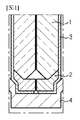
一方、図1を参照すると、従来のバッテリーモジュール構造が示されている。このような従来のバッテリーモジュール構造は、複数のフレーム2を用いて複数のパウチ型セル1を積層する場合、一対のパウチ型セル1それぞれの外側面上にプレート状の冷却フィン3を適用することで冷却効率を高める。
On the other hand, referring to FIG. 1, a conventional battery module structure is shown. In such a conventional battery module structure, when a plurality of pouch-
二次電池は、夏場のように高温環境で使用される場合があり、また、二次電池自体からも熱が発生し得る。このとき、複数の二次電池が積層されていると、二次電池の温度がさらに高くなり得るが、この温度が適正の温度よりも高くなれば二次電池の性能が低下し得、酷い場合は爆発や発火のおそれもある。したがって、バッテリーモジュールを構成するとき、パウチ型セル1の面と接触するように冷却フィン3を適用し、冷却フィン3をその下部に位置した冷却プレート4と接触させることで、バッテリーモジュールの全体的な温度上昇を防止する構成が多く用いられる。
The secondary battery may be used in a high temperature environment such as in summer, and heat may be generated from the secondary battery itself. At this time, if a plurality of secondary batteries are stacked, the temperature of the secondary battery may become higher, but if this temperature becomes higher than the appropriate temperature, the performance of the secondary battery may deteriorate, which is a severe case. May explode or catch fire. Therefore, when constructing the battery module, the
しかし、通常金属材質で構成される冷却フィン3を対面するパウチ型セル1の間に介在させてバッテリーモジュールを構成する場合、冷却フィン3とパウチ型セル1の表面との間で、材質の相違による接触熱抵抗が非常に大きくなり、またこのように単に金属の伝導性に依存する冷却方式だけでは、大きい発熱が発生する状況で十分な冷却が行われないおそれがあるという問題がある。
However, when the battery module is configured by interposing the
したがって、このような接触熱抵抗を減少させ、また単なる熱伝導方式の外に、より効率的に熱を放出できる冷却方式が適用されたバッテリーモジュール構造に対する開発が求められている。 Therefore, there is a need for development of a battery module structure to which a cooling method capable of reducing such contact thermal resistance and releasing heat more efficiently in addition to the simple heat conduction method is applied.
本発明は、上記問題点に鑑みてなされたものであり、冷却のための冷却媒体とバッテリーセルとが直接接触可能な冷却構造を適用したバッテリーモジュールを提供することで、高容量及び/または高出力のバッテリーモジュールの適用による発熱量の増加にも効率的に冷却を行うことを目的とする。 The present invention has been made in view of the above problems, and by providing a battery module to which a cooling structure capable of directly contacting a cooling medium for cooling and a battery cell is applied, a high capacity and / or a high capacity is provided. The purpose is to efficiently cool even if the amount of heat generated increases due to the application of the output battery module.
ただし、本発明が解決しようとする技術的課題は上述した課題に制限されず、他の課題は下記の発明の説明から当業者に明確に理解できるでしょう。 However, the technical problem to be solved by the present invention is not limited to the above-mentioned problems, and other problems can be clearly understood by those skilled in the art from the explanation of the invention below.
上述した課題を解決するため、本発明の一態様によるバッテリーモジュールは、複数のバッテリーセルが積層されて形成されたセル積層体と、前記セル積層体を収容し、前記セル積層体の下部、両側部、前後方及び上部をそれぞれ覆う下部ハウジング、一対の側部ハウジング、一対の前後方ハウジング及び上部ハウジングで構成されるモジュールハウジングと、を含み、前記下部ハウジングは、長手方向に沿って少なくとも一辺領域の内部に流路を形成する孔区間を有するベースプレートであって、前記セル積層体の下面を全体的に覆うベースプレートと、前記ベースプレートに予め決められた間隔毎に配置された複数のスペーサであって、前記セル積層体を前記ベースプレートの表面から離隔するように支持して前記セル積層体と前記ベースプレートとの間に空いた空間を形成する複数のスペーサと、を含み、前記孔区間は冷却媒体が前記空いた空間に供給されるように前記空いた空間と連通する。 In order to solve the above-mentioned problems, the battery module according to one aspect of the present invention accommodates a cell laminate formed by laminating a plurality of battery cells and the cell laminate, and lower and both sides of the cell laminate. A lower housing comprising a portion, anterior-rear and upper parts, a pair of side housings, a pair of anterior-rear housings and a module housing comprising an upper housing, wherein the lower housing has at least one side region along the longitudinal direction. A base plate having a hole section forming a flow path inside the base plate, which covers the entire lower surface of the cell laminate, and a plurality of spacers arranged at predetermined intervals on the base plate. , A plurality of spacers that support the cell laminate so as to be separated from the surface of the base plate and form a space between the cell laminate and the base plate, and the hole section contains a cooling medium. It communicates with the vacant space so as to be supplied to the vacant space.
前記複数のスペーサは、前記ベースプレートの長手方向の一側と他側とにそれぞれ備えられ、両端部が前記ベースプレートの両辺領域に接するように前記ベースプレートの幅方向に沿って延設された第1スペーサ及び第2スペーサを含み得る。 The plurality of spacers are provided on one side and the other side in the longitudinal direction of the base plate, respectively, and the first spacers are extended along the width direction of the base plate so that both ends are in contact with both side regions of the base plate. And a second spacer may be included.
前記複数のスペーサは、前記第1スペーサ及び第2スペーサと離隔してその間に備えられる少なくとも1つの第3スペーサをさらに含み得る。 The plurality of spacers may further include at least one third spacer that is spaced apart from the first spacer and the second spacer and is provided between them.
前記ベースプレートの前記少なくとも一辺領域は、相互対向する両辺領域に該当する第1側面部と第2側面部とに定義され、前記孔区間は、前記ベースプレートの外部から前記第1スペーサと前記第3スペーサとの間に位置した第1空いた空間まで連通するように前記第1側面部に形成される第1区間と、前記第1空いた空間から前記第3スペーサと前記第2スペーサとの間に位置した第2空いた空間まで連通するように前記第2側面部に形成される第2区間と、前記第2空いた空間から前記ベースプレートの外部まで連通するように前記第1側面部に形成される第3区間と、を含み得る。 The at least one side region of the base plate is defined as a first side surface portion and a second side surface portion corresponding to both side regions facing each other, and the hole section is defined as the first spacer and the third spacer from the outside of the base plate. A first section formed in the first side surface portion so as to communicate with the first vacant space located between the first vacant space and between the third spacer and the second spacer from the first vacant space. A second section formed in the second side surface portion so as to communicate with the located second vacant space, and a first side surface portion formed in the first side surface portion so as to communicate from the second vacant space to the outside of the base plate. 3rd section and may be included.
前記第3スペーサは、冷却媒体が通過するように内部を貫通する第3スペーサ流路を備え得る。 The third spacer may include a third spacer flow path that penetrates the interior to allow the cooling medium to pass through.
前記第1スペーサ及び前記第2スペーサは、それぞれ内部を貫通する第1スペーサ流路及び第2スペーサ流路を備え、前記孔区間と前記第1スペーサ流路とを連結する第1クーリングパイプと、前記孔区間と前記第2スペーサ流路とを連結する第2クーリングパイプとをさらに含み得る。 The first spacer and the second spacer are provided with a first spacer flow path and a second spacer flow path that penetrate the inside, respectively, and a first cooling pipe that connects the hole section and the first spacer flow path. A second cooling pipe connecting the hole section and the second spacer flow path may be further included.
前記ベースプレートの前記少なくとも一辺領域は、相互対向する両辺領域に該当する第1側面部と第2側面部とに定義され、前記第1側面部及び前記第2側面部は前記ベースプレートの他の部分より高く形成され、前記側部ハウジングの下端部に下方に突設された結合突起と型合わせられるように設けられた結合溝をさらに備え得る。 The at least one side region of the base plate is defined as a first side surface portion and a second side surface portion corresponding to both side regions facing each other, and the first side surface portion and the second side surface portion are from the other parts of the base plate. It may further be provided with a coupling groove that is formed high and is provided at the lower end of the side housing so as to be shaped with a coupling projection projecting downward.
前記第1側面部及び前記第2側面部は、前記セル積層体の最外郭の前記バッテリーセルに当接するように前記セル積層体に向かって延びた形態で突出した漏水防止顎をさらに備え得る。 The first side surface portion and the second side surface portion may further include a water leakage prevention jaw extending in a form extending toward the cell laminate so as to abut on the battery cell which is the outermost part of the cell laminate.
前記セル積層体とスペーサとの間には、前記セル積層体とスペーサとの間に冷却媒体が漏れないように接着剤が介在され得る。 An adhesive may be interposed between the cell laminate and the spacer so that the cooling medium does not leak between the cell laminate and the spacer.
前記ベースプレートの孔区間の一側及び他側にそれぞれ連結されて冷却媒体を前記空いた空間に流出入させる供給管及び排出管をさらに含み得る。 It may further include a supply pipe and a discharge pipe connected to one side and the other side of the hole section of the base plate to allow the cooling medium to flow in and out of the vacant space.
本発明の他の様態によれば、上述したバッテリーモジュールが複数個連結されて具現されるバッテリーパックが提供される。 According to another aspect of the present invention, there is provided a battery pack embodied by connecting a plurality of the above-mentioned battery modules.
本発明のさらに他の様態によれば、前記バッテリーパックを備える自動車が提供される。 According to still another aspect of the present invention, an automobile equipped with the battery pack is provided.
本発明の一態様によれば、冷却のための冷却媒体とバッテリーセルとが直接接触可能な冷却構造を適用したバッテリーモジュールを提供することで、高容量及び/または高出力のバッテリーモジュールの適用による発熱量の増加にも効率的に冷却を行うことができてバッテリーモジュールの性能向上をもたらすだけでなく、温度上昇によるバッテリーセルの発火/爆発などの安全事故を予防する効果も奏することができる。 According to one aspect of the present invention, by providing a battery module to which a cooling structure capable of directly contacting a cooling medium for cooling and a battery cell is applied, a high capacity and / or a high output battery module can be applied. It is possible to efficiently cool the battery even when the amount of heat generated increases, which not only improves the performance of the battery module, but also has the effect of preventing safety accidents such as ignition / explosion of the battery cell due to the temperature rise.
本明細書に添付される次の図面は、本発明の望ましい実施形態を例示するものであり、発明の詳細な説明とともに本発明の技術的な思想をさらに理解させる役割をするため、本発明は図面に記載された事項だけに限定されて解釈されてはならない。 The following drawings, which are attached to the present specification, illustrate desirable embodiments of the present invention and serve to further understand the technical idea of the present invention as well as a detailed description of the present invention. It should not be construed as being limited to the matters described in the drawings.
以下、添付された図面を参照して本発明の望ましい実施形態を詳しく説明する。これに先立ち、本明細書及び請求範囲に使われた用語や単語は通常的や辞書的な意味に限定して解釈されてはならず、発明者自らは発明を最善の方法で説明するために用語の概念を適切に定義できるという原則に則して本発明の技術的な思想に応ずる意味及び概念で解釈されねばならない。したがって、本明細書に記載された実施形態及び図面に示された構成は、本発明のもっとも望ましい一実施形態に過ぎず、本発明の技術的な思想のすべてを代弁するものではないため、本出願の時点においてこれらに代替できる多様な均等物及び変形例があり得ることを理解せねばならない。 Hereinafter, desirable embodiments of the present invention will be described in detail with reference to the accompanying drawings. Prior to this, the terms and words used herein and in the scope of the claims should not be construed in a general or lexicographical sense, and the inventor himself should explain the invention in the best possible way. It must be interpreted in the meaning and concept corresponding to the technical idea of the present invention in accordance with the principle that the concept of terms can be properly defined. Accordingly, the embodiments described herein and the configurations shown in the drawings are merely one of the most desirable embodiments of the invention and do not represent all of the technical ideas of the invention. It must be understood that at the time of filing, there may be a variety of equivalents and variants that can replace them.
まず、図2及び図3を参照して、本発明の一実施形態によるバッテリーモジュールの構成要素を概略的に説明する。 First, with reference to FIGS. 2 and 3, the components of the battery module according to the embodiment of the present invention will be schematically described.
図2は本発明の一実施形態によるバッテリーモジュールの外観を示した斜視図であり、図3は本発明の一実施形態によるバッテリーモジュールの分解斜視図である。 FIG. 2 is a perspective view showing the appearance of the battery module according to the embodiment of the present invention, and FIG. 3 is an exploded perspective view of the battery module according to the embodiment of the present invention.
これら図面を参照すると、本発明の一実施形態によるバッテリーモジュール10は、セル積層体100及びこれを収容するモジュールハウジング20を含む形態で具現される。また、前記モジュールハウジング20は、下部ハウジング200、一対の側部ハウジング300、一対の前後方ハウジング400及び上部ハウジング500を含む。
With reference to these drawings, the battery module 10 according to the embodiment of the present invention is embodied in a form including a
セル積層体100は、複数のバッテリーセル110を積層して得られるものであって、ここで用いられるバッテリーセル110は充放電可能な二次電池であれば特に制限されず、例えば、パウチ型バッテリーセル110が適用され得る。
The
バッテリーセル110は、それぞれ、一側及び他側に延びる一対の電極リード111を備え、このような電極リード111は正極リード及び負極リードを含む。積層されたそれぞれのバッテリーセル110同士の間は、後述するように、セル積層体100の下部に接触する絶縁油などの冷却媒体がセル積層体100を構成するバッテリーセル110間の空間を通って上部に浸透できないように、接着剤などによって堅固に固定/密閉されることが望ましい。
The
また、電極リード111は、セル積層体100を構成するバッテリーセル110が互いに直列連結、並列連結、または直列と並列との混合方式の連結を成すように、配置/連結され得る。
Further, the electrode leads 111 may be arranged / connected so that the
下部ハウジング200は、セル積層体100の下面を全体的に覆い、長手方向に沿って少なくとも一辺領域の内部に中空構造として流路を形成する孔区間213を備えたベースプレート210、及びセル積層体100を前記ベースプレート210の表面から離隔するように支持して前記セル積層体100とベースプレート210との間に空いた空間S1、S2を形成する複数のスペーサ220を含む形態で具現され得る。
The
ここで、前記空いた空間S1、S2は、セル積層体100、スペーサ220及びベースプレート210で囲まれて密閉された空間を意味する。このような空いた空間S1、S2と孔区間213とを連通させて冷却媒体を空いた空間に供給する。
Here, the vacant spaces S1 and S2 mean a closed space surrounded by the
前記冷却媒体は、供給管230及び排出管240を孔区間213の入口及び出口にそれぞれ連結することで、バッテリーモジュール10の内外に供給及び排出され得る。例えば、図4のように、供給管230は、バッテリーモジュール10の前方からベースプレート210の孔区間213の入口に連結され、排出管240は、バッテリーモジュール10の後方から孔区間213の出口に連結され得る。バッテリーモジュール10の内部における冷却媒体の流れについて詳しくは後述する。
The cooling medium can be supplied and discharged inside and outside the battery module 10 by connecting the
一対の側部ハウジング300は、それぞれセル積層体100の両側部を覆う部品であって、セル積層体100を構成するバッテリーセル110のうち両側の最外郭に配置されるバッテリーセル110の広い面と対面する。このような一対の側部ハウジング300は、セル積層体100を両側から加圧することで、セル積層体100を構成するバッテリーセル110同士の間にギャップが生じないようにする機能も果たすことができる。
Each of the pair of
一対の前後方ハウジング400は、それぞれバスバーフレーム410、絶縁カバー420及び前後方カバー430を含む形態で具現され得る。
The pair of front-
バスバーフレーム410は、セル積層体100の前方または後方からセル積層体100に結合されるものであって、バスバーフレーム410には電極リード111が挿入され、バッテリーセル110同士の電気的連結のための電極リード111の曲げ作業を容易にする。すなわち、電極リード111は、バスバーフレーム410に形成された挿入スリットを通って挿入されてから曲げられ、隣接した電極リード111同士の溶接などによって結合する。
The
絶縁カバー420は、バスバーフレーム410に挿入され曲げられて互いに結合した電極リード111のうち、互いに接触してはならない電極リード111同士が接触することを防止するために適用される部品であって、バスバーフレーム410上に結合されて外部の要因によって短絡が発生することを防止する。
The insulating
前後方カバー430は、絶縁カバー420上に結合される部品であって、セル積層体100、バスバーフレーム410及び絶縁カバー420などの内部部品を保護する機能を果たす。
The front /
上部ハウジング500は、セル積層体100の上部に配置され、上述したバスバーフレーム410を通って挿入され曲げられて電極リード111と電気的に連結されるセンシングアセンブリ510、及びセンシングアセンブリ510の上部に結合されて上部ハウジング500の最外層を構成するトッププレート520を含む形態で具現され得る。
The
次いで、図2及び図3と共に図4~図11を参照して、本発明の一実施形態によるバッテリーモジュール10の冷却構造についてより詳しく説明する。 Next, the cooling structure of the battery module 10 according to the embodiment of the present invention will be described in more detail with reference to FIGS. 4 to 11 together with FIGS. 2 and 3.
以下、図4及び図5に示したように、前記ベースプレート210において長手方向に沿って相互対向する両辺領域に該当する部分を第1側面部211と第2側面部212とに定義する。
Hereinafter, as shown in FIGS. 4 and 5, portions corresponding to both side regions facing each other in the longitudinal direction in the
前記第1側面部211及び第2側面部212は、ベースプレート210の他の部分(板面)よりも高く形成され得る。セル積層体100は、第1側面部211と第2側面部212との間で下面がスペーサ220によって支持されてベースプレート210の表面から離隔し、両側面が側部ハウジング300によって支持される。
The first
図6及び図7を参照すると、本実施形態による側部ハウジング300は、下端部に下方に突設された結合突起310を備える。そして、ベースプレート210の第1側面部211及び第2側面部212は、それぞれ、前記結合突起310と型合わせられるように設けられた結合溝Gを備える。このような結合溝Gに結合突起310を挿入/固定することで、側部ハウジング300をベースプレート210の第1側面部211及び第2側面部212に固定することができる。勿論、本実施形態と異なり、第1側面部211及び第2側面部212に結合突起310を設け、側部ハウジング300に結合溝Gを設けて、これらを固定結合させてもよい。
Referring to FIGS. 6 and 7, the
前記第1側面部211及び第2側面部212は、例えば、冷却媒体を空いた空間S1、S2に閉じ込めるフェンスのような役割を果たし、特にセル積層体100と接する個所に漏水防止顎Pをさらに備える。漏水防止顎Pは、図7に示したように、セル積層体100の最外郭のセルに当接するように、セル積層体100に向かって水平方向に延びた形態で提供され得る。このような漏水防止顎Pは、ベースプレート210とセル積層体100との間に隙間が生じて冷却媒体が漏水/漏油することを防止することができる。望ましくは、前記漏水防止顎Pに沿って接着剤がさらに介在されてもよい。
The first
また、スペーサ220は、セル積層体100の下面の形状に対応するように製作され得る。パウチ型バッテリーセル110の特性上、パウチ型バッテリーセル110から構成されたセル積層体100の下面が扁平でない点を考慮して、単位スペーサ220の上面をセル積層体100の下面の形状に合わせて製作することで、単位スペーサ220とセル積層体100の下面との間のギャップを無くすことができる。
Further, the
そして、前記セル積層体100とスペーサ220と間には、セル積層体100とスペーサ220との間に絶縁油などの冷却媒体が漏れないように接着剤が介在され、このような接着剤はセル積層体100とスペーサ220との間を結合/固定するだけでなく、ガスケットとしての機能も果たすようになる。
An adhesive is interposed between the
一方、前記スペーサ220は、互いに分離した形態で離隔して配置される複数の単位スペーサ220からなり得る。例えば、前記スペーサ220は、図5に示したように、ベースプレート210の長手方向の一側端部に備えられる第1スペーサ221、ベースプレート210の長手方向の他側端部に備えられる第2スペーサ222、及び第1スペーサ221及び第2スペーサ222と離隔し、これらの間に備えられる第3スペーサ223を含み得る。
On the other hand, the
ただし、このような単位スペーサ220の個数は、図示された3つに限らず、2つまたはそれ以上の個数で備えられてもよい。すなわち、第3スペーサ223は省略されてもよく、第1スペーサ221と第2スペーサ222と間に第3スペーサ223を含めた1つ以上の単位スペーサ220が互いに離隔して配置されてもよい。ただし、以下では説明の便宜上、単位スペーサ220が3つである場合を挙げて説明する。
However, the number of
前記単位スペーサ220は、ベースプレート210の幅方向に沿って並べた形態であって、両端部がベースプレート210の両辺領域、すなわち、第1側面部211及び第2側面部212に接するように配置される。セル積層体100は、前記単位スペーサ220上に載置されてその下面がベースプレート210の表面に接しない。これによって、セル積層体100とベースプレート210との間には、所定の空いた空間S1、S2が形成される。
The
図4~図11を参照して前記空いた空間S1、S2を見ると、前記空いた空間S1、S2は、セル積層体100及びベースプレート210によって上下が塞がれ、第1スペーサ221及び第2スペーサ222によって前後が塞がれ、第1側面部211及び第2側面部212によって左右が塞がれていることが分かる。そして、空いた空間S1、S2は、第3スペーサ223によって第1空いた空間S1と第2空いた空間S2とに区画され得る。前記第3スペーサ223は、セル積層体100に安定的な支持力を提供する構成要素であって、バッテリーセル110のサイズに応じて加減され得る。
Looking at the vacant spaces S1 and S2 with reference to FIGS. 4 to 11, the vacant spaces S1 and S2 are vertically closed by the
このような空いた空間S1、S2に冷却媒体を供給するための冷却媒体移動経路として、ベースプレート210の第1側面部211及び/または第2側面部212が活用される。上述したように、第1側面部211及び第2側面部212は、内部にベースプレート210の長手方向に沿って流路を形成して、空いた空間S1、S2と連通する孔区間213を備える。そして、孔区間213は、予め指定された位置毎に開口Oを有し、前記開口Oを通って冷却媒体が空いた空間S1、S2に流れ込むことができるように、空いた空間S1、S2と連通している。
As a cooling medium moving path for supplying the cooling medium to such vacant spaces S1 and S2, the first
本実施形態による孔区間213は、図5に示したように、第1側面部211に形成される第1区間213aと第3区間213c、そして第2側面部212に形成される第2区間213bを含む。
As shown in FIG. 5, the
前記第1区間213aは、孔区間213の入口から第1スペーサ221と第3スペーサ223と間に位置した第1空いた空間S1の一側までつながっている流路区間である。供給管230を通って外部から流れ込んだ冷却媒体は、第1区間213aに沿って移動し、第1区間213aの開口を通って第1空いた空間S1へと流れる。
The
第2区間213bは、第1空いた空間S1から第3スペーサ223と第2スペーサ222との間に位置した第2空いた空間S2までつながっている流路区間である。第2区間の開口Oは2つであって、第1空いた空間S1と第2空いた空間S2に対向するように形成されている。このような第2区間213bは、第1空いた空間S1の冷却媒体を第3スペーサ223を迂回して第2空いた空間S2に移動させる流路区間であると言える。
The
第3区間213cは、第2空いた空間S2から孔区間213の出口までつながっている流路区間である。第2空いた空間S2の冷却媒体は、前記第3区間213cに沿って移動して排出管240を通って外部へと排出される。
The
すなわち、冷却媒体の流れをまとめると、冷却媒体は、供給管230、第1区間213a、第1空いた空間S1、第2区間213b、第2空いた空間S2、第3区間213c、排出管240の順に移動する。このような冷却媒体の流れを有する本発明の一実施形態によるバッテリーモジュール10は、冷却媒体がバッテリーセル110に直接接触することで、従来に比べて高い冷却性能を示すことができる。
That is, when the flow of the cooling medium is summarized, the cooling medium is the
一方、本実施形態では孔区間213が3つであるが、これは単位スペーサ220及び空いた空間S1、S2の個数によるものであって、孔区間213の個数は単位スペーサ220及び空いた空間S1、S2の個数に合わせて自在に加減可能である。そして、前記孔区間213の入口または出口には、供給管230または排出管240の代わりに、2つのバッテリーモジュール10を連結するための継手(図示せず)が連結されてもよい。例えば、複数のバッテリーモジュール10を連結してバッテリーパック(図示せず)を構成する場合、1つのバッテリーモジュール10の孔区間213の出口と他の1つのバッテリーモジュール10の孔区間213の入口とを継手で連結してもよい。
On the other hand, in the present embodiment, there are three
以下、図12~図14を参照して、本発明の他の実施形態によるバッテリーモジュール10の冷却流路の構成を説明する。 Hereinafter, the configuration of the cooling flow path of the battery module 10 according to another embodiment of the present invention will be described with reference to FIGS. 12 to 14.
本発明の他の実施形態によるバッテリーモジュール10を説明するが、上述した実施形態と異なる部分を重点的に説明し、上述した実施形態についての説明と重なる部分は詳細な説明を省略する。 The battery module 10 according to another embodiment of the present invention will be described, but the parts different from the above-described embodiment will be mainly described, and the detailed description will be omitted for the parts that overlap with the above-mentioned description of the embodiment.
本発明の他の実施形態による第1スペーサ221、第2スペーサ222、第3スペーサ223は、それぞれ冷却媒体が通過できるように内部を貫通する流路を備える。第1スペーサ221~第3スペーサ223にそれぞれ対応する流路を第1スペーサ流路221a、第2スペーサ流路222a、第3スペーサ流路223aと称する。前記第1スペーサ流路221a~第3スペーサ流路223aは複数個形成され得る。
Each of the
また、本発明の他の実施形態によるバッテリーモジュール10は、第1スペーサ221の前方に設けられる第1クーリングパイプ250、及び第2スペーサ222の後方に設けられる第2クーリングパイプ260をさらに含み得る。
Further, the battery module 10 according to another embodiment of the present invention may further include a
第1クーリングパイプ250は、第1側面部211の一端に形成されている孔区間213と第1スペーサ221の前方に露出している複数の第1スペーサ流路221aとをそれぞれ個別的に連結する形態で提供される。これによって、冷却媒体が供給管230、孔区間213、第1クーリングパイプ250を通って第1スペーサ流路221aを通過し、第1空いた空間S1に流れ込むことができる。
The
第2クーリングパイプ260は、第1側面部211の他端に形成されている孔区間213と第2スペーサ222の後方に露出している複数の第2スペーサ流路222aとをそれぞれ個別的に連結する形態で提供される。これによって、冷却媒体が第2空いた空間S2から第2スペーサ流路222aを通過し、第2クーリングパイプ260と孔区間213を通って排出管240から外部に排出できる。
The
第3スペーサ223は、第1スペーサ流路221aを通って第1空いた空間S1に流れ込んだ冷却媒体を第2スペーサ222側に流すため、第3スペーサ223の内部を貫通する第3スペーサ流路223aを備える形態で提供され得る。
The
したがって、本実施形態によるバッテリーモジュール10の冷却媒体の流れをまとめると、冷却媒体は、供給管230、前方の孔区間213、第1クーリングパイプ250、第1スペーサ流路221a、第1空いた空間S1、第3スペーサ流路223a、第2空いた空間S2、第2クーリングパイプ260、後方の孔区間213、排出管240の順に移動してバッテリーモジュール10の外部に排出できる。
Therefore, when the flow of the cooling medium of the battery module 10 according to the present embodiment is summarized, the cooling medium is the
このような本実施形態は、冷却媒体が上述した実施形態と異なって、第3スペーサ223を迂回せずに通過できるため、ベースプレート210の第2側面部212に孔区間213を設けなくてもよい。また、孔区間213は、供給管230/第1クーリングパイプ250または第2クーリングパイプ260/排出管240の連結通路として比較的に短く形成されてもよい。
In this embodiment, unlike the above-described embodiment, the cooling medium can pass through the
上述したように、本発明によるバッテリーモジュール10は、セル積層体100とベースプレート210との間に部分的にスペーサ220を適用し、これによってセル積層体100とベースプレート210との間に形成される空いた空間S1、S2に冷却媒体を供給可能にすることで、セル積層体100を冷却媒体と直接接触させて冷却効率を極大化することができる。
As described above, the battery module 10 according to the present invention partially applies the
また、本発明によるバッテリーモジュール10は、このように冷却水、絶縁油などの液状の冷却媒体とバッテリーセル110とが直接接触する構造で生じ得る漏水/漏油の問題を解決できるように密封性を強化した構造を適用することで、製品の信頼性を高めることができる。
Further, the battery module 10 according to the present invention has a hermetically sealed property so as to solve the problem of water leakage / oil leakage that may occur in the structure in which the
また、上述したバッテリーモジュール10を複数個電気的に連結して具現する本発明の一実施形態によるバッテリーパック、及びこのようなバッテリーパックを備える自動車の場合も、このようなバッテリーモジュール10の長所を有して優れた性能を示すことができる。 Further, in the case of a battery pack according to an embodiment of the present invention in which a plurality of the above-mentioned battery modules 10 are electrically connected and realized, and an automobile provided with such a battery pack, the advantages of such a battery module 10 are also exhibited. It can show excellent performance.
以上のように、本発明の望ましい実施形態について図示して説明したが、本発明は上述した実施形態に限定されず、特許請求の範囲で請求する本発明の要旨から逸脱することなく、本発明が属する技術分野で通常の知識を持つ者であれば多様に変形実施できることは勿論、そのような変更も特許請求の範囲の記載の範囲内であることは言うまでもない。 As described above, the preferred embodiment of the present invention has been illustrated and described, but the present invention is not limited to the above-described embodiment, and the present invention does not deviate from the gist of the present invention claimed within the scope of claims. It goes without saying that a person who has ordinary knowledge in the technical field to which the invention belongs can carry out various modifications, and such changes are also within the scope of the claims.
一方、本明細書における上、下、左、右などのような方向を示した用語は、説明の便宜上使用されたものに過ぎず、観測者の位置や対象になる物の位置などによって変り得ることは本発明の当業者に自明である。 On the other hand, terms indicating directions such as up, down, left, right, etc. in the present specification are used only for convenience of explanation, and may change depending on the position of the observer, the position of the object, and the like. It is self-evident to those skilled in the art of the present invention.
1 パウチ型セル
2 フレーム
3 冷却フィン
4 冷却プレート
10 バッテリーモジュール
20 モジュールハウジング
100 セル積層体
110 パウチ型バッテリーセル、バッテリーセル
111 電極リード
200 下部ハウジング
210 ベースプレート
211 第1側面部
212 第2側面部
213 孔区間
213a 第1区間
213b 第2区間
213c 第3区間
220 単位スペーサ、スペーサ
221 第1スペーサ
221a 第1スペーサ流路
222 第2スペーサ
222a 第2スペーサ流路
223 第3スペーサ
223a 第3スペーサ流路
230 供給管
240 排出管
250 第1クーリングパイプ
260 第2クーリングパイプ
300 側部ハウジング
310 結合突起
400 前後方ハウジング
410 バスバーフレーム
420 絶縁カバー
430 前後方カバー
500 上部ハウジング
510 センシングアセンブリ
520 トッププレート
1
Claims (12)
前記セル積層体を収容し、前記セル積層体の下部、両側部、前後方及び上部をそれぞれ覆う下部ハウジング、一対の側部ハウジング、一対の前後方ハウジング及び上部ハウジングで構成されるモジュールハウジングと、
を含み、
前記下部ハウジングは、
長手方向に沿って少なくとも一辺領域の内部に流路を形成する孔区間を有するベースプレートであって、前記セル積層体の下面を全体的に覆うベースプレートと、
前記ベースプレートに予め決められた間隔毎に配置された複数のスペーサであって、前記セル積層体を前記ベースプレートの表面から離隔するように支持して前記セル積層体と前記ベースプレートとの間に空いた空間を形成する複数のスペーサと、
を含み、
前記孔区間は、冷却媒体が前記空いた空間に供給されるように前記空いた空間と連通し、
前記空いた空間を流れる前記冷却媒体は、前記セル積層体と接触する、バッテリーモジュール。 A cell laminate formed by stacking multiple battery cells,
A module housing comprising a lower housing, a pair of side housings, a pair of front-rear housings and an upper housing, which accommodates the cell laminate and covers the lower, both sides, front-rear and upper parts of the cell laminate, respectively.
Including
The lower housing
A base plate having a hole section forming a flow path inside at least one side region along the longitudinal direction, and a base plate that totally covers the lower surface of the cell laminate.
A plurality of spacers arranged on the base plate at predetermined intervals, supporting the cell laminate so as to be separated from the surface of the base plate, and providing a space between the cell laminate and the base plate. With multiple spacers that form the space,
Including
The hole section communicates with the vacant space so that the cooling medium is supplied to the vacant space .
The battery module in which the cooling medium flowing through the vacant space comes into contact with the cell laminate .
前記孔区間は、
前記ベースプレートの外部から前記第1スペーサと前記第3スペーサとの間に位置した第1空いた空間まで連通するように前記第1側面部に形成される第1区間と、
前記第1空いた空間から前記第3スペーサと前記第2スペーサとの間に位置した第2空いた空間まで連通するように前記第2側面部に形成される第2区間と、
前記第2空いた空間から前記ベースプレートの外部まで連通するように前記第1側面部に形成される第3区間と、
を含む、請求項3に記載のバッテリーモジュール。 The at least one side region of the base plate is defined as a first side surface portion and a second side surface portion corresponding to both side regions facing each other.
The hole section is
A first section formed in the first side surface portion so as to communicate from the outside of the base plate to the first vacant space located between the first spacer and the third spacer.
A second section formed on the second side surface portion so as to communicate from the first vacant space to the second vacant space located between the third spacer and the second spacer.
A third section formed on the first side surface portion so as to communicate from the second vacant space to the outside of the base plate.
3. The battery module according to claim 3.
前記孔区間と前記第1スペーサ流路とを連結する第1クーリングパイプと、前記孔区間と前記第2スペーサ流路とを連結する第2クーリングパイプとをさらに含む、請求項2、3、及び5のいずれか一項に記載のバッテリーモジュール。 The first spacer and the second spacer include a first spacer flow path and a second spacer flow path that penetrate the inside, respectively.
Claims 2, 3, and claims further include a first cooling pipe connecting the hole section and the first spacer flow path, and a second cooling pipe connecting the hole section and the second spacer flow path. The battery module according to any one of 5.
前記第1側面部及び前記第2側面部は前記ベースプレートの他の部分より高く形成され、前記側部ハウジングの下端部に下方に突設された結合突起と型合わせられるように設けられた結合溝をさらに備える、請求項1~6のいずれか一項に記載のバッテリーモジュール。 The at least one side region of the base plate is defined as a first side surface portion and a second side surface portion corresponding to both side regions facing each other.
The first side surface portion and the second side surface portion are formed higher than the other portions of the base plate, and are provided so as to be shaped with a coupling protrusion projecting downward at the lower end portion of the side housing. The battery module according to any one of claims 1 to 6, further comprising.
Applications Claiming Priority (3)
| Application Number | Priority Date | Filing Date | Title |
|---|---|---|---|
| KR1020180066302A KR102372348B1 (en) | 2018-06-08 | 2018-06-08 | Battery module with improved cooling structure |
| KR10-2018-0066302 | 2018-06-08 | ||
| PCT/KR2019/002747 WO2019235724A1 (en) | 2018-06-08 | 2019-03-08 | Battery module having improved cooling structure |
Publications (2)
| Publication Number | Publication Date |
|---|---|
| JP2021504888A JP2021504888A (en) | 2021-02-15 |
| JP7082665B2 true JP7082665B2 (en) | 2022-06-08 |
Family
ID=68770909
Family Applications (1)
| Application Number | Title | Priority Date | Filing Date |
|---|---|---|---|
| JP2020528094A Active JP7082665B2 (en) | 2018-06-08 | 2019-03-08 | Battery module with improved cooling structure |
Country Status (6)
| Country | Link |
|---|---|
| US (2) | US11811040B2 (en) |
| EP (1) | EP3716392A4 (en) |
| JP (1) | JP7082665B2 (en) |
| KR (1) | KR102372348B1 (en) |
| CN (1) | CN111373597B (en) |
| WO (1) | WO2019235724A1 (en) |
Families Citing this family (9)
| Publication number | Priority date | Publication date | Assignee | Title |
|---|---|---|---|---|
| USD999046S1 (en) * | 2019-10-17 | 2023-09-19 | Carrier Corporation | Battery access door for electronic mortise door lock |
| KR20210088170A (en) * | 2020-01-06 | 2021-07-14 | 주식회사 엘지에너지솔루션 | Battery pack with improved safety and secondary battery including the same |
| KR20210092566A (en) * | 2020-01-16 | 2021-07-26 | 주식회사 엘지에너지솔루션 | Battery module and battery pack including the same |
| KR20210131593A (en) * | 2020-04-24 | 2021-11-03 | 주식회사 엘지에너지솔루션 | Battery module and battery pack including the same |
| KR20220008558A (en) * | 2020-07-14 | 2022-01-21 | 주식회사 엘지에너지솔루션 | Battery pack and device including the same |
| KR20220066699A (en) | 2020-11-16 | 2022-05-24 | 주식회사 엘지에너지솔루션 | Battery module having a cooling structure using insulating oil, and a battery pack and vehicle comprising the same |
| KR20220066698A (en) * | 2020-11-16 | 2022-05-24 | 주식회사 엘지에너지솔루션 | Battery module having a cooling structure using insulating oil, and a battery pack and vehicle comprising the same |
| WO2024002623A1 (en) * | 2022-06-30 | 2024-01-04 | Robert Bosch Gmbh | A support member and a battery pack with the same |
| CN220774608U (en) * | 2022-09-26 | 2024-04-12 | Sk新能源株式会社 | Shell for battery module and battery pack |
Citations (12)
| Publication number | Priority date | Publication date | Assignee | Title |
|---|---|---|---|---|
| US6465123B1 (en) | 1999-07-01 | 2002-10-15 | Daimlerchrysler Ag | Battery container and motor vehicle |
| US20120270095A1 (en) | 2011-04-21 | 2012-10-25 | Myung-Chul Kim | Battery module |
| WO2013103254A1 (en) | 2012-01-04 | 2013-07-11 | 에스케이이노베이션 주식회사 | Battery module |
| US20140272508A1 (en) | 2013-03-15 | 2014-09-18 | Vecture Inc. | Battery pack system |
| JP2015106527A (en) | 2013-12-02 | 2015-06-08 | サーチウェア株式会社 | Battery pack and mobile mounting the same |
| US20150229010A1 (en) | 2014-02-10 | 2015-08-13 | Samsung Sdi Co., Ltd. | Battery pack |
| DE102015214185A1 (en) | 2015-07-27 | 2017-02-02 | Audi Ag | Battery module for a motor vehicle, module assembly and motor vehicle |
| US20170191567A1 (en) | 2016-01-04 | 2017-07-06 | Hyundai Motor Company | Valve for controlling coolant flow and fuel cell cooling system using the same |
| WO2018062863A1 (en) | 2016-09-28 | 2018-04-05 | 주식회사 엘지화학 | Battery module having cooling flow path, method for assembling same, and frame assembly |
| EP3316340A1 (en) | 2016-10-26 | 2018-05-02 | Samsung SDI Co., Ltd. | Battery module |
| EP3331060A1 (en) | 2016-03-16 | 2018-06-06 | LG Chem, Ltd. | Battery module |
| JP2018518032A (en) | 2015-09-24 | 2018-07-05 | エルジー・ケム・リミテッド | Battery module |
Family Cites Families (17)
| Publication number | Priority date | Publication date | Assignee | Title |
|---|---|---|---|---|
| US6068946A (en) * | 1998-08-02 | 2000-05-30 | Motorola, Inc. | Dual cover battery casing |
| EP1878085B1 (en) * | 2005-03-14 | 2016-04-20 | Johnson Controls Technology Company | Lithium battery system |
| KR20060102851A (en) | 2005-03-25 | 2006-09-28 | 삼성에스디아이 주식회사 | Secondary battery module |
| WO2010148224A2 (en) * | 2009-06-18 | 2010-12-23 | Jason Fuhr | Battery module having a cell tray with thermal management features |
| US9291405B2 (en) * | 2011-08-02 | 2016-03-22 | Ford Global Technologies, Llc | Battery pack liquid channel and coldplate cooling system |
| JP2014220089A (en) * | 2013-05-08 | 2014-11-20 | 小島プレス工業株式会社 | Battery pack |
| KR20150000378A (en) * | 2013-06-21 | 2015-01-02 | 타이코에이엠피(유) | A battery module package |
| KR102233774B1 (en) * | 2014-02-17 | 2021-03-30 | 삼성에스디아이 주식회사 | Battery module |
| KR101619449B1 (en) * | 2014-10-24 | 2016-05-10 | 주식회사 고산 | Extrusion type heat exchanger for battery |
| EP3154103B1 (en) * | 2015-10-07 | 2019-02-27 | Samsung SDI Co., Ltd. | Battery module including a housing floor with integrated cooling |
| KR102184753B1 (en) * | 2016-05-24 | 2020-11-30 | 주식회사 엘지화학 | Battery module, battery pack comprising the battery module and vehicle comprising the battery pack |
| KR102235655B1 (en) * | 2016-06-17 | 2021-04-01 | 에스케이이노베이션 주식회사 | Secondary battery pack |
| KR102295950B1 (en) | 2016-06-17 | 2021-08-30 | 에스케이이노베이션 주식회사 | Cooling and supporting structure for secondary battery, and secondary battery pack including the same |
| US10700395B2 (en) * | 2016-08-09 | 2020-06-30 | Nio Usa, Inc. | Battery module housing having an integrally-formed cooling plate |
| KR101806733B1 (en) * | 2016-08-31 | 2017-12-07 | 현대자동차주식회사 | Cooling structure for battery cell |
| KR102565380B1 (en) | 2016-12-07 | 2023-08-10 | 삼성디스플레이 주식회사 | Thin film transistor substrate |
| CN111357131B (en) * | 2017-09-29 | 2022-12-06 | 罗伯特·博世有限公司 | Battery pack including battery cell limiter |
-
2018
- 2018-06-08 KR KR1020180066302A patent/KR102372348B1/en active IP Right Grant
-
2019
- 2019-03-08 JP JP2020528094A patent/JP7082665B2/en active Active
- 2019-03-08 WO PCT/KR2019/002747 patent/WO2019235724A1/en unknown
- 2019-03-08 CN CN201980005785.2A patent/CN111373597B/en active Active
- 2019-03-08 US US16/767,457 patent/US11811040B2/en active Active
- 2019-03-08 EP EP19814466.9A patent/EP3716392A4/en active Pending
-
2023
- 2023-09-26 US US18/372,864 patent/US20240030517A1/en active Pending
Patent Citations (14)
| Publication number | Priority date | Publication date | Assignee | Title |
|---|---|---|---|---|
| US6465123B1 (en) | 1999-07-01 | 2002-10-15 | Daimlerchrysler Ag | Battery container and motor vehicle |
| US20120270095A1 (en) | 2011-04-21 | 2012-10-25 | Myung-Chul Kim | Battery module |
| WO2013103254A1 (en) | 2012-01-04 | 2013-07-11 | 에스케이이노베이션 주식회사 | Battery module |
| US20140272508A1 (en) | 2013-03-15 | 2014-09-18 | Vecture Inc. | Battery pack system |
| JP2015106527A (en) | 2013-12-02 | 2015-06-08 | サーチウェア株式会社 | Battery pack and mobile mounting the same |
| US20150229010A1 (en) | 2014-02-10 | 2015-08-13 | Samsung Sdi Co., Ltd. | Battery pack |
| DE102015214185A1 (en) | 2015-07-27 | 2017-02-02 | Audi Ag | Battery module for a motor vehicle, module assembly and motor vehicle |
| JP2018518032A (en) | 2015-09-24 | 2018-07-05 | エルジー・ケム・リミテッド | Battery module |
| US20170191567A1 (en) | 2016-01-04 | 2017-07-06 | Hyundai Motor Company | Valve for controlling coolant flow and fuel cell cooling system using the same |
| EP3331060A1 (en) | 2016-03-16 | 2018-06-06 | LG Chem, Ltd. | Battery module |
| JP2019502232A (en) | 2016-03-16 | 2019-01-24 | エルジー・ケム・リミテッド | Battery module |
| WO2018062863A1 (en) | 2016-09-28 | 2018-04-05 | 주식회사 엘지화학 | Battery module having cooling flow path, method for assembling same, and frame assembly |
| JP2019507469A (en) | 2016-09-28 | 2019-03-14 | エルジー・ケム・リミテッド | BATTERY MODULE HAVING COOLING FLOW |
| EP3316340A1 (en) | 2016-10-26 | 2018-05-02 | Samsung SDI Co., Ltd. | Battery module |
Also Published As
| Publication number | Publication date |
|---|---|
| EP3716392A4 (en) | 2021-03-17 |
| US11811040B2 (en) | 2023-11-07 |
| WO2019235724A1 (en) | 2019-12-12 |
| EP3716392A1 (en) | 2020-09-30 |
| US20240030517A1 (en) | 2024-01-25 |
| US20200395643A1 (en) | 2020-12-17 |
| JP2021504888A (en) | 2021-02-15 |
| CN111373597A (en) | 2020-07-03 |
| KR20190139620A (en) | 2019-12-18 |
| KR102372348B1 (en) | 2022-03-07 |
| CN111373597B (en) | 2023-11-24 |
Similar Documents
| Publication | Publication Date | Title |
|---|---|---|
| JP7082665B2 (en) | Battery module with improved cooling structure | |
| KR102119183B1 (en) | Battery module | |
| KR102120118B1 (en) | Battery module | |
| JP7062175B2 (en) | Battery pack with degassing flow path | |
| KR102050025B1 (en) | Battery Pack of coolant direct contact cooling type | |
| KR101608853B1 (en) | Frame for secondary battery and battery module including the same | |
| KR101792751B1 (en) | Battery module | |
| US9460862B2 (en) | Electric storage cell, electric storage apparatus, and vehicle having electric storage apparatus | |
| JP7055203B2 (en) | Battery module with improved cooling efficiency and battery pack containing it | |
| WO2014192087A1 (en) | Laminate-type lithium-ion secondary battery module | |
| KR20120074425A (en) | Battery module and battery pack employed with the same | |
| KR102026386B1 (en) | Battery module | |
| KR20210074779A (en) | Cell module to prevent gas movement to nearby modules | |
| JP7045605B2 (en) | Battery module with improved cooling structure | |
| KR20180023699A (en) | Battery module | |
| EP3792992B1 (en) | Battery module comprising module housing | |
| KR20220142853A (en) | Battery pack and manufacturing method thereof | |
| CN220400796U (en) | Battery module including connection member | |
| US20230402678A1 (en) | Battery Pack and Device Including the Same | |
| EP4203144A1 (en) | Battery module and battery pack comprising same |
Legal Events
| Date | Code | Title | Description |
|---|---|---|---|
| A621 | Written request for application examination |
Free format text: JAPANESE INTERMEDIATE CODE: A621 Effective date: 20200521 |
|
| A131 | Notification of reasons for refusal |
Free format text: JAPANESE INTERMEDIATE CODE: A131 Effective date: 20210726 |
|
| A521 | Request for written amendment filed |
Free format text: JAPANESE INTERMEDIATE CODE: A523 Effective date: 20211020 |
|
| A711 | Notification of change in applicant |
Free format text: JAPANESE INTERMEDIATE CODE: A712 Effective date: 20211222 |
|
| TRDD | Decision of grant or rejection written | ||
| A01 | Written decision to grant a patent or to grant a registration (utility model) |
Free format text: JAPANESE INTERMEDIATE CODE: A01 Effective date: 20220516 |
|
| A61 | First payment of annual fees (during grant procedure) |
Free format text: JAPANESE INTERMEDIATE CODE: A61 Effective date: 20220527 |
|
| R150 | Certificate of patent or registration of utility model |
Ref document number: 7082665 Country of ref document: JP Free format text: JAPANESE INTERMEDIATE CODE: R150 |