EP3792434A1 - Lock assembly of a motor vehicle - Google Patents
Lock assembly of a motor vehicle Download PDFInfo
- Publication number
- EP3792434A1 EP3792434A1 EP20185026.0A EP20185026A EP3792434A1 EP 3792434 A1 EP3792434 A1 EP 3792434A1 EP 20185026 A EP20185026 A EP 20185026A EP 3792434 A1 EP3792434 A1 EP 3792434A1
- Authority
- EP
- European Patent Office
- Prior art keywords
- clamping
- rotary latch
- clamping device
- lock arrangement
- closing element
- Prior art date
- Legal status (The legal status is an assumption and is not a legal conclusion. Google has not performed a legal analysis and makes no representation as to the accuracy of the status listed.)
- Withdrawn
Links
Images


Classifications
-
- E—FIXED CONSTRUCTIONS
- E05—LOCKS; KEYS; WINDOW OR DOOR FITTINGS; SAFES
- E05B—LOCKS; ACCESSORIES THEREFOR; HANDCUFFS
- E05B77/00—Vehicle locks characterised by special functions or purposes
- E05B77/36—Noise prevention; Anti-rattling means
- E05B77/38—Cushion elements, elastic guiding elements or holding elements, e.g. for cushioning or damping the impact of the bolt against the striker during closing of the wing
-
- E—FIXED CONSTRUCTIONS
- E05—LOCKS; KEYS; WINDOW OR DOOR FITTINGS; SAFES
- E05B—LOCKS; ACCESSORIES THEREFOR; HANDCUFFS
- E05B83/00—Vehicle locks specially adapted for particular types of wing or vehicle
- E05B83/16—Locks for luggage compartments, car boot lids or car bonnets
- E05B83/18—Locks for luggage compartments, car boot lids or car bonnets for car boot lids or rear luggage compartments
-
- E—FIXED CONSTRUCTIONS
- E05—LOCKS; KEYS; WINDOW OR DOOR FITTINGS; SAFES
- E05B—LOCKS; ACCESSORIES THEREFOR; HANDCUFFS
- E05B85/00—Details of vehicle locks not provided for in groups E05B77/00 - E05B83/00
- E05B85/02—Lock casings
-
- E—FIXED CONSTRUCTIONS
- E05—LOCKS; KEYS; WINDOW OR DOOR FITTINGS; SAFES
- E05B—LOCKS; ACCESSORIES THEREFOR; HANDCUFFS
- E05B85/00—Details of vehicle locks not provided for in groups E05B77/00 - E05B83/00
- E05B85/04—Strikers
- E05B85/045—Strikers for bifurcated bolts
Definitions
- the invention is directed to a lock arrangement of a motor vehicle, having a lock housing, a rotary latch rotatably mounted on the lock housing, which can be moved between a closed position encompassing a closing element and an open position releasing the closing element, and a pawl mounted pivotably on the lock housing, which is between a Engagement position, in which the pawl is in engagement with the rotary latch arranged in its closed position, and a release position releasing the rotary latch is movably mounted, the lock housing having an inlet slot extending up to the rotary latch, in which the closing element is immersed in the closed position of the rotary latch is arranged.
- a lock arrangement of the type mentioned above is, for example, from DE 10 2016 102 227 A1 known.
- lock arrangements which are usually composed of a locking element attached to the body of the motor vehicle and a locking element located in or on a door or flap of the motor vehicle and having a rotary latch and a pawl
- a locking element attached to the body of the motor vehicle and a locking element located in or on a door or flap of the motor vehicle and having a rotary latch and a pawl
- These relative movements are possible, for example, in the lateral direction of the inlet slot, into which the closing element is immersed during a closing process, due to the play between the closing element and the rotary latch, and generate undesirable noises.
- the relative movements lead to unnecessary friction between the closing element and the rotary latch, which has a detrimental effect on the wear and tear and the service life of the components involved in the relative movements.
- the invention is based on the object of creating a solution which provides an improved lock arrangement in a structurally simple manner, by means of which the aforementioned disadvantages are avoided and in which the lateral play between the locking element and the rotary latch is reduced to a minimum.
- a clamping device designed to variably narrow the inlet slot is attached to the lock housing, the clamping device being designed with functional surfaces and between an inlet position in which the functional surfaces move towards the closing element of the rotary latch are arranged in a leading aligned manner, and a clamping position in which the functional surfaces are arranged in an aligned manner so as to clamp the closing element, is designed to be movable.
- the clamping device does not reduce or narrow the inlet slot itself, but rather the free cross section of the inlet slot into which the closing element moves during the closing process, the reduction of the free cross section being variable and consequently different depending on the position (inlet position or clamping position) of the clamping device he follows.
- the reduction in the free cross section of the inlet slot is greater in the clamping position than in the inlet position, the clamping device reducing the free cross section of the inlet slot both in the clamping position and in the inlet position.
- the invention provides a lock arrangement which is characterized by a simple construction.
- a clamping device on the lock housing which is designed to be variably narrowing the inlet slot is appropriate, it is possible to reduce the play known from the prior art to a minimum.
- the expression "variably narrowing" is to be understood in the sense of the invention that the free cross-sectional area lying between the functional areas can be changed in size and extent, the variability being dependent on the position of the clamping device, the position of the clamping device in turn depending on the position of the closing element is dependent. In the run-in position, the functional surfaces are aligned in such a way that the guide surfaces guide the closing element in the direction of the rotary latch.
- the functional surfaces form an inlet opening through which a lateral offset of the closing element is compensated during a closing process and the closing element is guided in the direction of the rotary latch.
- the clamping device consequently "centers" the closing element when, during a closing process, the closing element moves with a lateral offset in the direction of the rotary latch.
- the functional surfaces are then arranged in such a way that the functional surfaces clamp the closing element, which means that there is no longer any play between the rotary latch and the closing element, so that rattling noise is avoided and there is no friction between these two components, which is advantageous affects the service life of the entire lock assembly.
- the invention provides that the clamping device comprises at least two clamping elements, which are arranged opposite one another on opposite sides of the inlet slot, one of the functional surfaces being formed on a respective clamping element.
- a functional surface that guides and clamps the closing element is formed on each clamping element.
- the clamping device can variably narrow the inlet slot and consequently reduce the free cross-section between the functional surfaces differently, it is structurally particularly favorable in an embodiment of the invention if the clamping elements are pivotably mounted on the lock housing, with the functional surfaces completely within the clamping device at least in the clamping position of the inlet slot are arranged horizontally.
- the invention provides in a further embodiment that in the entry position of the clamping device the functional surfaces form an intermediate space with a maximum entry width between them, wherein in the entry position of the clamping device the functional surfaces in the direction of the rotary latch with a decreasing distance to each other are aligned converging.
- a further embodiment of the invention provides that, in the clamping position of the clamping device, the functional surfaces form an intermediate space with a maximum clamping width between them, the clamping width being smaller than the maximum inlet width.
- the clamping width corresponds at most to a cross-sectional width of the closing element.
- the invention also provides that the maximum inlet width is smaller than a slot width of the inlet slot.
- an offset of the closing element during the closing process is compensated directly by the clamping device, so that the closing element does not come into contact with the inlet slot.
- the invention in an embodiment of the first embodiment then provides that a respective functional surface is divided into a clamping section and a guide-retaining section is subdivided, wherein in the clamping position of the clamping device the respective clamping sections are arranged converging or running parallel to each other in a direction pointing to the rotary latch, and wherein in the clamping position of the clamping device the respective guide-retaining sections in a protruding from the inlet slot Direction inclined and arranged to run towards one another.
- the distance between the guide-retaining sections thus decreases in a direction pointing away from the rotary latch.
- a rounded portion is formed between a respective clamping section and a respective guide-retaining section, in which the closing element is arranged in sections in a pre-locking position of the rotary latch and pawl.
- the rounding thus represents a defined and precisely defined position of the closing element and clamping device for the pre-locking position.
- the closing element in a main locking position of the rotary latch and pawl, is arranged clamped between the respective clamping sections. This also represents a defined and precisely defined position of the closing element and clamping device for the main locking position.
- a respective functional surface has a guide-retaining section and a rounded section, with the respective guide-retaining sections being inclined in a direction pointing out of the inlet slot in the clamping position of the clamping device are arranged to run towards one another, and wherein in the clamping position of the clamping device the respective rounded sections form a circular segment-shaped clamping section, in which the closing element is arranged to be clamped at least in sections.
- the rounded sections consequently encompass and encompass the outer circumference of the closing element at least in sections, so that the closing element is arranged without play within the circular section-shaped clamping section.
- a respective clamping element is held on the lock housing via a clamping bracket, with a respective clamping element being pivotably mounted on the associated clamping bracket is.
- a respective clamping bracket has a first movement-limiting surface on which the associated clamping element is arranged in the inlet position.
- the invention provides in a further refinement that a respective clamping bracket has a second movement-limiting surface on which the associated clamping element is arranged in the clamping position in contact.
- the invention provides that a swivel arm and a swivel recess are formed on a respective clamping element, with a respective swivel arm of one clamping element extending in the direction of the other clamping element.
- the swivel arms serve to synchronize the movement of the two clamping elements if the closing element should dip into the inlet slot with a large lateral offset.
- the laterally offset closing element is guided by the guide-retaining section of the one clamping element and centered, whereas the closing element comes into contact with the swivel arm of the other clamping element, so that when the closing element moves in the direction of the rotary latch, the closing element swivels the clamping element over the swivel arm in the direction of the clamping position.
- the invention provides that the swivel arm of a clamping element is designed to move through the swivel recess of the other clamping element when the clamping device moves from the inlet position into the clamping position.
- a respective swivel arm of the one clamping element extends over the free end of the swivel arm of the other clamping element.
- the invention provides, in a configuration of the second embodiment, that the swivel arms are offset from one another and are designed to allow movement of the swivel arms past the respective clamping element, so that in the entry position of the clamping device, the swivel arms are arranged so as to cross one another and in the clamping position of the clamping device, the pivot arms are arranged overlapping at least in sections. This avoids a collision of the swivel arms when the clamping device moves.
- the invention provides in a further development of the second embodiment that an actuation space is formed between a free end of one swivel arm and the functional surface of the other swivel arm in the entry position of the clamping device , which has a width which is smaller than a maximum cross-sectional width of the closing element.
- a respective clamping element is coupled to a mechanical restoring element, the respective mechanical restoring element being designed to exert a restoring force on the associated clamping element that urges the clamping device into the inlet position.
- the clamping device is designed in such a way that the clamping elements are always pushed into the inlet position assigned to it.
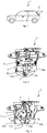
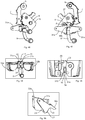
- FIG 1 a motor vehicle 1 in the form of a car is shown by way of example, which in the example has a flap or tailgate 2 which can be locked and opened using a lock arrangement 3 according to the invention. They show Figures 2 to 25 a first embodiment of the lock assembly 3 according to the invention, whereas the Figures 26 to 50 show a second embodiment of the lock arrangement 3 according to the invention.
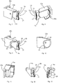
- FIGS Figures 2 and 3 perspective views for the in Figure 1 Lock arrangement 3 indicated merely by way of example, a lock housing 4 of the lock arrangement 3 and a locking element 5 being apparent from the figures.
- a rotary latch 6 is rotatably mounted on the lock housing 4, with a pawl 7 also being pivotably mounted on the lock housing 4.
- the rotary latch 6 can be moved between a closed position and an open position, the rotary latch 6 engaging around the closing element 5 in the closed position and the rotary latch 6 releasing the closing element 5 in the open position.
- the pawl 7 is also movably supported between an engagement position and a release position. In the engagement position the pawl 7 is in engagement with the rotary latch 6 arranged in its closed position, whereas in the release position the pawl 7 releases the rotary latch 6 so that the rotary latch 6 can rotate.
- the rotary latch 6 is mounted on the lock housing 4 so as to be rotatable about an axis of rotation 8, whereas the pawl 7 is mounted on the lock housing 4 so as to be pivotable on a pivot axis 9. From the component representation of the Figure 4 the individual components of the lock arrangement 3 according to the invention can be better seen, the lock housing 4 in the illustrated embodiment being made in two parts with a first housing element 4a and a second housing element 4b.
- the first and second housing elements 4a and 4b are connected to one another via a detachable snap-in connection.
- An inlet slot 10 is formed on the first housing element 4a of the lock housing 4 (see for example Figure 4 ), which extends up to the rotary latch 6.
- the closing element 5 plunges into the inlet slot 10 and, as is known, enters a mouth of the rotary latch 6, so that the rotary latch 6 engages around and fixes the closing element 5 in its closed position.
- the closing element 5 is arranged immersed in the inlet slot 10 of the lock housing 4.
- the lock arrangement 3 is characterized by a clamping device 11 which is attached to the lock housing 4 and which is arranged on the inlet slot 10.
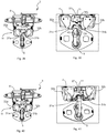
- the clamping device 11 of the lock assembly 3 is from the Figures 2 to 15 visible, with the Figures 7 to 13 show individual details of the clamping device 11.
- the clamping device 11 is designed in such a way that, when the lock device 3 is closed, the clamping device 11 variably narrows the free cross section of the inlet slot 10.
- the closing element 5 consequently does not come into contact with the edge of the inlet slot 10 during a closing process. Rather, the closing element 5 comes into contact with the clamping device 11 during a closing process Reduce the free cross section of the inlet slot 10 variably.
- variable means that the clamping device 11 is between an inlet position (see for example Figures 14 and 16 ) and a clamping position (see for example Figures 15 and 22nd ) is designed to be movable.
- the functional surfaces 12a, 12b of the closing element 5 are arranged so as to lead in the direction of the rotary latch 6, whereas in the clamping position the functional surfaces 12a, 12b of the closing element 5 are arranged so as to be clamped.
- the clamping device 11 in the first embodiment comprises two clamping elements 14a and 14b.
- the two clamping elements 14a and 14b are arranged opposite one another on opposite sides of the inlet slot 10.
- Each individual clamping element 14a, 14b has a functional surface 12a, 12b assigned to it.
- One of the functional surfaces 12a, 12b is thus formed on a respective clamping element 14a, 14b.
- the functional surfaces 12a, 12b of the clamping elements 14a, 14b are arranged lying within the inlet slot 10. At least a predominant portion of each functional surface 12a, 12b is arranged lying within the inlet slot 10.
- the inlet slot 10 has a slot width 15 from Figure 4 can be seen. Furthermore, in the entry position of the clamping device 11, the functional surfaces 12a, 12b form an intermediate space 16 with a maximum entry width 17 (see FIG Figure 14 ). The maximum inlet width 17 is smaller than the slot width 15 of the inlet slot 10 in the inlet position and in the clamping position Figure 14 As can be seen, the functional surfaces 12a, 12b are aligned in the direction of the rotary latch 6 with a decreasing distance 18 from one another, converging. Consequently, in the entry position of the clamping device 11, the functional surfaces 12a, 12b lead the closing element 5 in the direction of the rotary latch 6.
- the functional surfaces 12a, 12b are arranged pivoted with respect to the entry position in the clamping position of the clamping device 11, as shown Figure 15 can be seen, so that the clamping elements 14a and 14b are consequently mounted pivotably on the lock housing 4.
- the functional surfaces 12a and 12b form the space 16 between them, which, however, compared to the entry position, has a maximum clamping width 19 which is smaller than the maximum entry width 17 (see FIG Figure 15 ).
- the dimensioning of the maximum clamping width 19 is based on the cross-section or diameter of the closing element 5 and corresponds at most to the cross-section of the bow-shaped and circular in cross-section closing element 5, because in the clamping position the functional surfaces 12a and 12b of the clamping device 11 clamp the closing element 5 at least in sections between them and block a lateral movement of the closing element 5 in the direction of the side edges of the inlet slot 10.
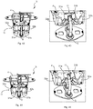
- a respective functional surface 12a, 12b is divided into a clamping section 20 and a guide-retaining section 21.
- the respective clamping sections 20 are arranged running parallel to one another, whereas the respective guide-retaining sections 21 are inclined in a direction pointing away from the rotary latch 6 and are arranged running towards one another, so that the retaining sections 21 adjoin their end pointing away from the rotary latch 6 close off the intermediate space 16 and thus block a movement of the closing element 5 located in the intermediate space 16 out of the intermediate space 16 in a direction pointing away from the rotary latch 6.
- the respective clamping sections 20 can be arranged converging towards one another in a direction pointing towards the rotary latch 6.
- a respective functional surface 12a, 12b also has a respective fillet 28.
- the respective fillet 28 is arranged between a respective clamping section 20 and a respective guide-retaining section 21.
- the closing element 5 is arranged in sections in the respective fillet 28 when the rotary latch 6 and the pawl 7 are arranged in a pre-locking position (see, for example, FIG Figures 20 and 21 ). In the pre-locking position, the locking element 5 has a little play. Consequently, when the clamping device 11 moves from the inlet position into the clamping position, the closing element 5 moves over the fillet 28.
- clamping elements 14a and 14b are not mounted directly on the lock housing 4. Rather, a respective clamping element 14a, 14b is held on the lock housing 4 via a clamping holder 22a and 22b, with a respective clamping element 14a, 14b on the associated clamping holder 22a, 22b is pivotably mounted.
- Each clamp holder 22a, 22b is attached to the lock housing 4 via a plug connection, each clamp holder 22a, 22b having an insertion slot 25a and 25b, respectively.
- a respective clamping bracket 22a, 22b with its insertion slot 25a, 25b is slipped onto a connection extension 26a, 26b configured to correspond to the respective insertion slot 25a, 25b (see for example Figure 4 ).
- a first movement-limiting surface 23, on which the associated clamping element 14a, 14b rests in the run-in position, and a second movement-limiting surface 24, are provided on a respective clamp holder 22a, 22b. on which the associated clamping element 14a, 14b is arranged resting in the clamping position, formed, for example, in the Figures 9 and 10 is shown, where in Figure 9 the clamping element 14a rests against the second movement-limiting surface 24.
- Figure 9 FIG. 13 shows a view in which the clamp holder 22a is shown partially cut, so that the first delimiting surface 23 and the second delimiting surface 24 can be seen.
- a mechanical restoring element urges a respective clamping element 14a, 14b into the inlet position. Consequently, a respective clamping element 14a, 14b is coupled to the associated mechanical restoring element, the respective and associated mechanical restoring element being designed to exert a restoring force on the associated clamping element 14a, 14b that urges the clamping device 11 into the inlet position.
- the restoring force is overcome by the closing element 5, as a result of which the clamping elements 14a, 14b are pivoted from the entry position into the clamping position.
- clamping element 14b and the clamping bracket 22b are designed identically to the clamping section 20 and the guide-retaining section 21.
- the clamping element 14b and the clamping bracket 22b are, however, designed mirror-symmetrically to the clamping element 14a and the clamping bracket 22a, so that the clamping device 11 is formed from a pair of clamping elements 14a, 14b and clamping brackets 22a, 22b, which are correspondingly designed mirror-symmetrically to one another.
- FIG. 16 and 17 a position of the closing element 5 at the beginning of the closing process is shown, in which the clamping device 11 is arranged in its inlet position and the clamping elements 14a and 14b are in contact with the respective first movement limiting surface 23 of the associated clamping brackets 22a, 22b.
- the functional surfaces 12a and 12b are inclined and converge towards one another in the direction of the rotary latch 6 and are arranged in a funnel shape, so that the functional surfaces 12a and 12b guide the closing element 5 in the direction of the rotary latch 6.
- a lateral offset of the closing element 5 in the direction of the clamping element 14a or the clamping element 14b is compensated by the clamping device 11, wherein in the Figures 16 and 17 a lateral offset of the closing element 5 in the direction of the clamping element 14a is shown.
- FIGS 18 and 19 show an arrangement in which the closing element 5 from the in Figure 16 The position shown is moved into the space 16 formed between the functional surfaces 12a, 12b of the clamping device 11 has, where Figure 19 a detailed view of the Figure 18 shows.
- the lateral offset of the closing element 5 is compensated for by the functional surface 12a, the functional surface 12a quasi-centering the closing element 5 and guiding it in the direction of the rotary latch 6.
- the guide retaining sections 21 thus block a movement of the closing element 5 in a direction pointing away from the rotary latch 6.
- the closing element 5 is arranged at least in sections in the respective fillet 28 of the clamping elements 14a, 14b with a small amount of play.
- the rotary latch 6 is arranged in its closed position, the rotary latch 6 and the pawl 7 being arranged in a main locking position.
- the closing element 5 is on a buffer element 27 (see for example Figure 4 ) arranged adjacent, which limits a movement of the closing element 5 beyond the functional surfaces 12a, 12b in the direction of the rotary latch 6.
- the buffer element 27 blocks a movement of the locking element 5 out of the intermediate space 16 formed by the functional surfaces 12a, 12b in addition to the guide-retaining sections 21.
- the buffer element 27 is attached to the lock housing 4 and closes flush with the ends of the respective clamping portions 20, as it is, for example, from the Figures 22, 23 and 25 can be seen.
- the pawl 7 is in engagement with the rotary latch 6 arranged in its closed position, the closing element 5 being arranged in the mouth of the rotary latch 6 so that the rotary latch 6 engages around and fixes the closing element 5 in sections.
- the clamping sections 20 of the respective clamping elements 14a, 14b block a movement of the closing element 5 to the side edges of the inlet slot 10, so that the clamping device 11 holds the closing element 5 fixed in its clamping position.
- the closing element 5 slides along one of the two guide-retaining sections 21 until the closing element 5 reaches the corresponding fillet 28. From this position, the closing element 5 is guided further via a rotary movement of the clamping elements 14a, 14b until the clamping elements 14a, 14b come into contact with the second movement-limiting surfaces 24. In this position, the latching position of the rotary latch 6 and the pawl 7 is reached, the locking element 5 still having a certain amount of play.
- the closing element 5 slides over the respective clamping sections 20 until the main locking position of the rotary latch 6 and pawl 7 is reached.
- the closing element 5 is arranged clamped by the clamping device 11 without play.
- the second embodiment is in the Figures 26 to 50 shown, only the differences from the first embodiment being described below in order to avoid repetition.
- the Figure 26 shows a perspective view of the second embodiment of the lock arrangement according to the invention 3, which also includes the lock housing 4 formed from the first housing element 4a and the second housing element 4b (in Figure 26 only the first housing element 4a is shown), the rotary latch 6 mounted rotatably about the pivot axis 8 and the pawl 7 mounted pivotably about the pivot axis 9, the rotary latch 6 and the pawl 7 form a lock for the locking element 5, with the
- the rotary latch 6 is movably mounted on the lock housing 4 between the closed position encompassing the closing element 5 and the open position releasing the closing element 5, whereas the pawl 7 is movably supported between the engagement position in which it is in engagement with the rotary latch 6 arranged in its closed position, and the release position, in which the pawl 7 releases the rotary latch 6, is movably supported on the lock housing 4.
- the first housing element 4a of the lock housing 4 is shown in FIG Figure 27 shown, wherein the first housing element 4a of the second embodiment differs from the first housing element 4a of the first embodiment by the formation of the inlet slot 10, which extends as far as the rotary latch 6.
- the slot width 29 is dimensioned smaller than the slot width 15 of the first embodiment.
- the second embodiment also has, for the lock arrangement 3 according to the invention, the clamping device 11 attached to the lock housing 4 and arranged on the inlet slot 10, which in its entirety consists, for example, of the Figures 26 and 28 can be seen and which is also designed such that in one Closing process of the lock device 3, the clamping device 11 variably narrows the free cross section of the inlet slot 10. As a result, the closing element 5 comes into contact with the clamping device 11 during a closing process.
- the clamping device 11 is also designed with functional surfaces 30a and 30b in the second embodiment, which during a closing process variably reduce the free cross-section of the inlet slot 10 by the clamping device 11 between an inlet position (see for example Figure 36 ) and a clamping position (see for example Figure 37 ) is designed to be movable.
- the functional surfaces 30a and 30b are arranged to guide the closing element 5 in the direction of the rotary latch 6, whereas in the clamping position, the functional surfaces 30a and 30b are arranged to be oriented so as to clamp the closing element 5.
- the functional surfaces 30a and 30b are arranged lying completely within the inlet slot 10 (see for example Figure 49 ).
- the clamping device 11 also has two clamping elements 31a and 31b, which are arranged opposite one another on opposite sides of the inlet slot 10 and which are pivotably mounted on the lock housing 4.
- Each individual clamping element 31a and 31b has a respective functional surface 30a and 30b assigned to it.
- One of the functional surfaces 30a, 30b is thus formed on a respective clamping element 31a, 31b.
- the clamping elements 31a and 31b are each held on the lock housing 4 via a clamping bracket 32a and 32b, a respective clamping element 31a, 31b being pivotably mounted on the associated clamping bracket 32a, 32b.
- a first movement limiting surface 23 is formed, on which the associated clamping element 31a, 31b is arranged resting in the inlet position, as is shown, for example, in the sectional view of FIG Figure 50 shows.
- a second movement-limiting surface is not provided in the second embodiment.
- a mechanical restoring element urges a respective clamping element 31a, 31b into the inlet position, so that a respective clamping element 31a, 31b is coupled to the associated mechanical restoring element, which exerts a restoring force on the clamping device 11 into the inlet position associated clamping element 31a, 31b is formed exercising.
- the restoring force is overcome by the closing element 5, as a result of which the clamping elements 31a, 31b are pivoted from the entry position into the clamping position.
- the functional surfaces 30a, 30b form an intermediate space 16 with a maximum entry width 17 (see FIG Figure 36 ).
- the maximum inlet width 17 in the clamping position is smaller than the slot width 29 of the inlet slot 10 (see for example Figure 49 ).
- the functional surfaces 30a, 30b are also aligned in the direction of the rotary latch 6 with a decreasing distance 18 from one another, converging (see FIG Figure 36 ), so that the functional surfaces 30a, 30b guide the closing element 5 in the direction of the rotary latch 6.
- the functional surfaces 30a, 30b are arranged pivoted with respect to the inlet position, as shown in FIG Figure 37 can be seen.
- the functional surfaces 30a and 30b form the intermediate space 16 between them, but this is the case in comparison for the inlet position is designed with a maximum clamping width 19, which is smaller than the maximum inlet width 17 (see Figure 37 ).
- the dimensioning of the maximum clamping width 19 is based on the cross-section or diameter of the closing element 5 and corresponds at most to the cross-section of the bow-shaped and circular in cross-section closing element 5, because in the clamping position the functional surfaces 30a and 30b of the clamping device 11 clamp the closing element 5 at least in sections between them and block a lateral movement of the closing element 5 in the direction of the side edges of the inlet slot 10.
- a respective functional surface 30a, 30b has the guide-retaining section 21 and a rounded section 33.
- the respective guide-retaining sections 21 are inclined in a direction pointing out of the inlet slot 10 and are arranged to run towards one another (see, for example, FIG Figure 36 ), so that the retaining sections 21 close off the intermediate space 16 at their end pointing away from the rotary latch 6 and thus block a movement of the closing element 5 located in the intermediate space 16 out of the intermediate space 16 in a direction pointing away from the rotary latch 6.
- the respective rounded sections 33 form a circular segment-shaped clamping section 34, in which the closing element 5 is arranged at least in sections so as to be clamped (see for example Figures 37 , 48 and 49 ).
- the clamping bracket 32a is designed identical and mirror-symmetrical to the clamping bracket 32a and has a receiving chamber 35 for the movable mounting of the clamping element 31a or 31b as well as the insertion slot 25a for fastening the Clamp bracket 32a on the lock housing 4.
- the clamping device 11 of the second embodiment is formed from a pair of clamping elements 31a, 31b and clamping brackets 32a, 32b, wherein the clamping brackets 32a, 32b can be designed mirror-symmetrically to one another, whereas the two clamping elements 31a and 31b are designed asymmetrically to one another, as will be explained below .
- a pivot arm 36a or 36b and a pivot recess 37a or 37b are formed, such as the Figures 32 and 33 can be found.
- the pivot arm 36a of the clamping element 31a extends in the direction of the clamping element 31b
- the pivot arm 36b of the clamping element 31b extends in the direction of the clamping element 31a.
- a respective pivot arm 36a, 36b of the one clamping element 31a, 31b extends in the direction of the other clamping element 31b, 31a.
- the two clamping elements 31a and 31b are designed asymmetrically to one another.
- the pivot arms 36a and 36b are offset from one another and arranged on the respective clamping element 31a, 31b that a movement of the clamping elements 31a, 31b is allowed, in which the pivot arms 36a and 36b can move past one another.
- the swivel arms 36a, 36b are arranged in such a way that they cross one another (see for example Figures 36 and 38 ), whereas in the clamping position of the clamping device 11 the pivot arms 36a, 36b are arranged so as to overlap at least in sections (see for example Figures 37 and 44 ).
- the respective pivot recesses 37a and 37b allow this movement of the pivot arms 36a and 36b.
- the pivot arm 36a of the clamping element 31a is designed to move through the pivoting recess 37b of the other clamping element 31b when the clamping device 11 is moved from the inlet position into the clamping position.
- Swivel arm 36b of the clamping element 31b is designed to move through the swiveling recess 37a of the other clamping element 31a when the clamping device 11 is moved from the inlet position into the clamping position.
- the pivot arms 36a and 36b serve to pivot the clamping elements 31a and 31b essentially synchronously when the closing element 5 moves in the direction of the rotary latch 6 and dips into the inlet slot 10 with a transverse offset in relation to the latter.
- an actuation space 38a or 38b is formed between a free end of a pivot arm 36a or 36b and the functional surface 30b or 30a of the other pivot arm 36b or 36a which has a width 39 which is smaller than a maximum cross-sectional width 40 of the closing element 5. This relationship is shown in FIG Figure 39 shown for the actuation space 38b.
- FIG. 38 and 39 a position of the closing element 5 at the beginning of the closing process is shown, in which the clamping device 11 is arranged in its inlet position and the clamping elements 31a and 31b on the respective first movement limiting surface 23 of the associated Clamp brackets 32a, 32b are in contact.
- the functional surfaces 30a and 30b are inclined and converge in the direction of the rotary latch 6 and are arranged in a funnel shape, so that the functional surfaces 30a and 30b guide the closing element 5 in the direction of the rotary latch 6.
- a lateral offset of the closing element 5 in the direction of the clamping element 31a or the clamping element 31b is compensated by the clamping device 11, wherein in the Figures 38 and 39 a lateral offset of the closing element 5 in the direction of the clamping element 31a is shown.
- the pivot arms 36a and 36b are crossed and arranged one behind the other, so that the respective actuating spaces 38a and 38b are formed in the inlet position.
- the Figures 40 and 41 show an arrangement in which the closing element 5 from the in Figure 38 position shown has moved into the intermediate space 16 formed between the functional surfaces 30a, 30b of the clamping device 11.
- the lateral offset of the closing element 5 is already slightly compensated for by the functional surface 30a, the functional surface 30a quasi-centering the closing element 5 and guiding it in the direction of the rotary latch 6.
- the rotary latch 6 is arranged in its closed position and is in engagement with the pawl 7.
- the closing element 5 is on the buffer element 27 (see for example Figure 47 ) arranged adjacent, which limits a movement of the closing element 5 in the direction of the rotary latch 6.
- the buffer element 27 thus blocks a movement of the closing element 5 in addition to the rounded sections 33.
- the respective guide-retaining sections 21 are inclined and arranged to run towards one another in a direction pointing away from the rotary latch 6. As a result, the guide retaining sections 21 block a movement of the closing element 5 in a direction pointing away from the rotary latch 6.
- the pawl 7 is in engagement with the rotary latch 6 arranged in its closed position, the closing element 5 being arranged in the mouth of the rotary latch 6 so that the rotary latch 6 engages around and fixes the closing element 5 in sections.
- the rounded sections 33 forming the clamping section 34 of the respective clamping elements 31a, 31b block a movement of the closing element 5 to the side edges of the inlet slot 10 so that the clamping device 11 holds the closing element 5 fixed in its clamping position.
Abstract
Die Erindung betrifft eine Schlossanordnung (3) eines Kraftfahrzeugs (1), aufweisend ein Schlossgehäuse (4), eine drehbar an dem Schlossgehäuse (4) gelagerte Drehfalle (6) und eine schwenkbar an dem Schlossgehäuse (4) gelagerte Sperrklinke (7), wobei das Schlossgehäuse (4) einen sich bis zu der Drehfalle (6) erstreckenden Einlaufschlitz (10) aufweist, in welchem ein Schließelement (5) in einer Schließstellung der Drehfalle (6) eingetaucht angeordnet ist. Dabei ist eine den Einlaufschlitz (10) variabel schmälernd ausgebildete Klemmvorrichtung (11) an dem Schlossgehäuse (4) angebracht, wobei die Klemmvorrichtung (11) mit Funktionsflächen (12a, 12b; 30a, 30b) ausgebildet ist und zwischen einer Einlaufstellung, in welcher die Funktionsflächen (12a, 12b; 30a, 30b) das Schließelement (5) in Richtung der Drehfalle (6) führend ausgerichtet angeordnet sind, und einer Klemmstellung, in welcher die Funktionsflächen (12a, 12b; 30a, 30b) das Schließelement (5) einklemmend ausgerichtet angeordnet sind, bewegbar ausgebildet ist.The invention relates to a lock arrangement (3) of a motor vehicle (1), comprising a lock housing (4), a rotary latch (6) mounted rotatably on the lock housing (4) and a pawl (7) mounted pivotably on the lock housing (4), whereby the lock housing (4) has an inlet slot (10) which extends up to the rotary latch (6) and in which a closing element (5) is arranged immersed in a closed position of the rotary latch (6). A clamping device (11) designed to narrow the inlet slot (10) is attached to the lock housing (4), the clamping device (11) being designed with functional surfaces (12a, 12b; 30a, 30b) and between an inlet position in which the Functional surfaces (12a, 12b; 30a, 30b) the closing element (5) are arranged oriented in the direction of the rotary latch (6), and a clamping position in which the functional surfaces (12a, 12b; 30a, 30b) clamp the closing element (5) are arranged aligned, is designed to be movable.
Description
Die Erfindung richtet sich auf eine Schlossanordnung eines Kraftfahrzeugs, aufweisend ein Schlossgehäuse, eine drehbar an dem Schlossgehäuse gelagerte Drehfalle, welche zwischen einer ein Schließelement umgreifenden Schließstellung und einer das Schließelement freigebenden Offenstellung bewegbar ist, und eine schwenkbar an dem Schlossgehäuse gelagerte Sperrklinke, welche zwischen einer Eingriffsstellung, in welcher die Sperrklinke mit der in ihrer Schließstellung angeordneten Drehfalle in Eingriff steht, und einer die Drehfalle freigebenden Freigabestellung bewegbar gelagert ist, wobei das Schlossgehäuse einen sich bis zu der Drehfalle erstreckenden Einlaufschlitz aufweist, in welchem das Schließelement in der Schließstellung der Drehfalle eingetaucht angeordnet ist.The invention is directed to a lock arrangement of a motor vehicle, having a lock housing, a rotary latch rotatably mounted on the lock housing, which can be moved between a closed position encompassing a closing element and an open position releasing the closing element, and a pawl mounted pivotably on the lock housing, which is between a Engagement position, in which the pawl is in engagement with the rotary latch arranged in its closed position, and a release position releasing the rotary latch is movably mounted, the lock housing having an inlet slot extending up to the rotary latch, in which the closing element is immersed in the closed position of the rotary latch is arranged.
Eine Schlossanordnung der vorstehend genannten Art ist beispielsweise aus der
Der Erfindung liegt die Aufgabe zugrunde eine Lösung zu schaffen, die auf konstruktiv einfache Weise eine verbesserte Schlossanordnung bereitstellt, durch welche die vorstehend genannten Nachteile vermieden werden und bei welcher das seitliche Spiel zwischen Schließelement und Drehfalle auf ein Minimum reduziert wird.The invention is based on the object of creating a solution which provides an improved lock arrangement in a structurally simple manner, by means of which the aforementioned disadvantages are avoided and in which the lateral play between the locking element and the rotary latch is reduced to a minimum.
Bei einer Schlossanordnung eines Kraftfahrzeugs der eingangs bezeichneten Art wird die Aufgabe erfindungsgemäß dadurch gelöst, dass eine den Einlaufschlitz variabel schmälernd ausgebildete Klemmvorrichtung an dem Schlossgehäuse angebracht ist, wobei die Klemmvorrichtung mit Funktionsflächen ausgebildet ist und zwischen einer Einlaufstellung, in welcher die Funktionsflächen das Schließelement in Richtung der Drehfalle führend ausgerichtet angeordnet sind, und einer Klemmstellung, in welcher die Funktionsflächen das Schließelement einklemmend ausgerichtet angeordnet sind, bewegbar ausgebildet ist. Die Klemmvorrichtung verkleinert bzw. schmälert dabei nicht den Einlaufschlitz selbst, sondern vielmehr den freien Querschnitt des Einlaufschlitzes, in welchen sich das Schließelement beim Schließvorgang hineinbewegt, wobei die Verkleinerung des freien Querschnitts variabel und folglich unterschiedlich in Abhängigkeit der Stellung (Einlaufstellung oder Klemmstellung) der Klemmvorrichtung erfolgt. Dabei ist die Verkleinerung des freien Querschnitts des Einlaufschlitzes in der Klemmstellung größer als in der Einlaufstellung, wobei die Klemmvorrichtung sowohl in der Klemmstellung als auch in der Einlaufstellung den freien Querschnitt des Einlaufschlitzes verkleinert.In the case of a lock arrangement of a motor vehicle of the type described at the outset, the object is achieved according to the invention in that a clamping device designed to variably narrow the inlet slot is attached to the lock housing, the clamping device being designed with functional surfaces and between an inlet position in which the functional surfaces move towards the closing element of the rotary latch are arranged in a leading aligned manner, and a clamping position in which the functional surfaces are arranged in an aligned manner so as to clamp the closing element, is designed to be movable. The clamping device does not reduce or narrow the inlet slot itself, but rather the free cross section of the inlet slot into which the closing element moves during the closing process, the reduction of the free cross section being variable and consequently different depending on the position (inlet position or clamping position) of the clamping device he follows. The reduction in the free cross section of the inlet slot is greater in the clamping position than in the inlet position, the clamping device reducing the free cross section of the inlet slot both in the clamping position and in the inlet position.
Vorteilhafte und zweckmäßige Ausgestaltungen und Weiterbildungen der Erfindung ergeben sich aus den Unteransprüchen.Advantageous and expedient configurations and developments of the invention emerge from the subclaims.
Durch die Erfindung wird eine Schlossanordnung zur Verfügung gestellt, welche sich durch eine einfache Konstruktion auszeichnet. Dadurch, dass eine den Einlaufschlitz variabel schmälernd ausgebildete Klemmvorrichtung an dem Schlossgehäuse angebracht ist, ist die Reduzierung des aus dem Stand der Technik bekannten Spiels auf ein Minimum möglich. Unter dem Ausdruck "variabel schmälernd" ist im Sinne der Erfindung zu verstehen, dass die zwischen den Funktionsflächen liegende freie Querschnittsfläche veränderbar in Größe und Ausmaß ist, wobei die Veränderbarkeit in Abhängigkeit der Stellung der Klemmvorrichtung erfolgt, wobei die Stellung der Klemmvorrichtung wiederum von der Position des Schließelements abhängig ist. In der Einlaufstellung sind die Funktionsflächen derart ausgerichtet, dass die Führungsflächen das Schließelement in Richtung der Drehfalle führen. Dabei bilden die Funktionsflächen eine Einlauföffnung aus, durch welche bei einem Schließvorgang ein seitlicher Versatz des Schließelements kompensiert und das Schließelement in Richtung der Drehfalle geführt wird. Die Klemmvorrichtung "zentriert" folglich das Schließelement, wenn bei einem Schließvorgang sich das Schließelement mit einem seitlichen Versatz in Richtung der Drehfalle bewegt. In der Klemmstellung sind die Funktionsflächen dann derart ausgerichtet angeordnet, dass die Funktionsflächen das Schließelement einklemmen, wodurch kein Spiel mehr zwischen Drehfalle und Schließelement vorhanden ist, so dass eine klappernde Geräuschentwicklung vermieden wird und keine Reibung zwischen diesen beiden Bauteilen vorhanden ist, was sich vorteilhaft auf die Lebensdauer der gesamten Schlossanordnung auswirkt.The invention provides a lock arrangement which is characterized by a simple construction. In that a clamping device on the lock housing, which is designed to be variably narrowing the inlet slot is appropriate, it is possible to reduce the play known from the prior art to a minimum. The expression "variably narrowing" is to be understood in the sense of the invention that the free cross-sectional area lying between the functional areas can be changed in size and extent, the variability being dependent on the position of the clamping device, the position of the clamping device in turn depending on the position of the closing element is dependent. In the run-in position, the functional surfaces are aligned in such a way that the guide surfaces guide the closing element in the direction of the rotary latch. The functional surfaces form an inlet opening through which a lateral offset of the closing element is compensated during a closing process and the closing element is guided in the direction of the rotary latch. The clamping device consequently "centers" the closing element when, during a closing process, the closing element moves with a lateral offset in the direction of the rotary latch. In the clamping position, the functional surfaces are then arranged in such a way that the functional surfaces clamp the closing element, which means that there is no longer any play between the rotary latch and the closing element, so that rattling noise is avoided and there is no friction between these two components, which is advantageous affects the service life of the entire lock assembly.
Die Erfindung sieht in Ausgestaltung vor, dass die Klemmvorrichtung zumindest zwei Klemmelemente umfasst, die auf sich gegenüberliegenden Seiten des Einlaufschlitzes sich gegenüberliegend angeordnet sind, wobei an einem jeweiligen Klemmelement jeweils eine der Funktionsflächen ausgebildet ist. Somit ist an einem Klemmelement jeweils eine das Schließelement führend und festklemmend ausgebildete Funktionsfläche ausgebildet.In an embodiment, the invention provides that the clamping device comprises at least two clamping elements, which are arranged opposite one another on opposite sides of the inlet slot, one of the functional surfaces being formed on a respective clamping element. Thus, a functional surface that guides and clamps the closing element is formed on each clamping element.
Damit die Klemmvorrichtung den Einlaufschlitz variabel schmälern und folglich den freien Querschnitt zwischen den Funktionsflächen unterschiedlich verkleinern kann, ist es in Ausgestaltung der Erfindung konstruktiv besonders günstig, wenn die Klemmelemente an dem Schlossgehäuse schwenkbar gelagert sind, wobei die Funktionsflächen zumindest in der Klemmstellung der Klemmvorrichtung vollständig innerhalb des Einlaufschlitzes liegend angeordnet sind.So that the clamping device can variably narrow the inlet slot and consequently reduce the free cross-section between the functional surfaces differently, it is structurally particularly favorable in an embodiment of the invention if the clamping elements are pivotably mounted on the lock housing, with the functional surfaces completely within the clamping device at least in the clamping position of the inlet slot are arranged horizontally.
Zur Kompensierung eines seitlichen Versatzes des Schließelements bei einem Schließvorgang sieht die Erfindung in weiterer Ausgestaltung vor, dass in der Einlaufstellung der Klemmvorrichtung die Funktionsflächen einen Zwischenraum mit einer maximalen Einlaufbreite zwischen sich ausbilden, wobei in der Einlaufstellung der Klemmvorrichtung die Funktionsflächen in Richtung der Drehfalle mit einem abnehmenden Abstand zueinander aufeinander zulaufend ausgerichtet sind.To compensate for a lateral offset of the closing element during a closing process, the invention provides in a further embodiment that in the entry position of the clamping device the functional surfaces form an intermediate space with a maximum entry width between them, wherein in the entry position of the clamping device the functional surfaces in the direction of the rotary latch with a decreasing distance to each other are aligned converging.
Für ein spielfreies Festklemmen des Schließelements ist dann in einer weiteren Ausgestaltung der Erfindung vorgesehen, dass in der Klemmstellung der Klemmvorrichtung die Funktionsflächen einen Zwischenraum mit einer maximalen Klemmbreite zwischen sich ausbilden, wobei die Klemmbreite kleiner ist als die maximale Einlaufbreite. Dabei entspricht die Klemmbreite maximal einer Querschnittsbreite des Schließelements.For a backlash-free clamping of the closing element, a further embodiment of the invention provides that, in the clamping position of the clamping device, the functional surfaces form an intermediate space with a maximum clamping width between them, the clamping width being smaller than the maximum inlet width. The clamping width corresponds at most to a cross-sectional width of the closing element.
In Ausgestaltung einer ersten Ausführungsform sieht die Erfindung ferner vor, dass die maximale Einlaufbreite kleiner ist als eine Schlitzbreite des Einlaufschlitzes. Bei dieser Ausgestaltung wird ein Versatz des Schließelements beim Schließvorgang direkt von der Klemmvorrichtung kompensiert, so dass das Schließelement gar nichts erst in Kontakt mit dem Einlaufschlitz gelangt.In an embodiment of a first embodiment, the invention also provides that the maximum inlet width is smaller than a slot width of the inlet slot. In this embodiment, an offset of the closing element during the closing process is compensated directly by the clamping device, so that the closing element does not come into contact with the inlet slot.
Im Hinblick auf eine vorteilhafte Führungs- und Klemmwirkung der Funktionsflächen sieht die Erfindung in Ausgestaltung der ersten Ausführungsform dann vor, dass eine jeweilige Funktionsfläche in einen Klemm-Abschnitt und einen Führungs-Rückhalte-Abschnitt unterteilt ist, wobei in der Klemmstellung der Klemmvorrichtung die jeweiligen Klemm-Abschnitte in eine zu der Drehfalle weisende Richtung aufeinander zulaufend oder parallel zueinander verlaufend angeordnet sind, und wobei in der Klemmstellung der Klemmvorrichtung die jeweiligen Führungs-Rückhalte-Abschnitte in eine aus dem Einlaufschlitz herausweisende Richtung geneigt und aufeinander zu verlaufend angeordnet sind. Der Abstand zwischen den Führungs-Rückhalte-Abschnitten nimmt somit in eine von der Drehfalle wegweisende Richtung ab.With a view to an advantageous guiding and clamping effect of the functional surfaces, the invention in an embodiment of the first embodiment then provides that a respective functional surface is divided into a clamping section and a guide-retaining section is subdivided, wherein in the clamping position of the clamping device the respective clamping sections are arranged converging or running parallel to each other in a direction pointing to the rotary latch, and wherein in the clamping position of the clamping device the respective guide-retaining sections in a protruding from the inlet slot Direction inclined and arranged to run towards one another. The distance between the guide-retaining sections thus decreases in a direction pointing away from the rotary latch.
Gemäß einer weiteren Ausgestaltung der ersten Ausführungsform ist es von Vorteil, wenn zwischen einem jeweiligen Klemmabschnitt und einem jeweiligen Führungs-Rückhalte-Abschnitt eine Ausrundung ausgebildet ist, in welcher das Schließelement in einer Vorrastposition von Drehfalle und Sperrklinke abschnittsweise angeordnet ist. Die Ausrundung stellt somit für die Vorrastposition eine definierte und genau festgelegte Position von Schließelement und Klemmvorrichtung dar.According to a further refinement of the first embodiment, it is advantageous if a rounded portion is formed between a respective clamping section and a respective guide-retaining section, in which the closing element is arranged in sections in a pre-locking position of the rotary latch and pawl. The rounding thus represents a defined and precisely defined position of the closing element and clamping device for the pre-locking position.
Bei der ersten Ausführungsform ist ferner vorgesehen, dass in einer Hauptrastposition von Drehfalle und Sperrklinke das Schließelement zwischen den jeweiligen Klemm-Abschnitten eingeklemmt angeordnet ist. Dies stellt zusätzlich für die Hauptrastposition eine definierte und genau festgelegte Position von Schließelement und Klemmvorrichtung dar.In the first embodiment it is further provided that in a main locking position of the rotary latch and pawl, the closing element is arranged clamped between the respective clamping sections. This also represents a defined and precisely defined position of the closing element and clamping device for the main locking position.
Die Erfindung sieht in Ausgestaltung für eine zweite Ausführungsform vor, dass eine jeweilige Funktionsfläche einen Führungs-Rückhalte-Abschnitt und einen Ausrundungs-Abschnitt aufweist, wobei in der Klemmstellung der Klemmvorrichtung die jeweiligen Führungs-Rückhalte-Abschnitte in eine aus dem Einlaufschlitz herausweisende Richtung geneigt und aufeinander zu verlaufend angeordnet sind, und wobei in der Klemmstellung der Klemmvorrichtung die jeweiligen Ausrundungs-Abschnitte einen kreisabschnittsförmigen Klemmungs-Abschnitt ausbilden, in welchem das Schließelement zumindest abschnittsweise festklemmend angeordnet ist. Die Ausrundungs-Abschnitte umfassen und umgreifen folglich den Außenumfang des Schließelements zumindest abschnittsweise, so dass das Schließelement innerhalb des kreisabschnittsförmigen Klemmungs-Abschnitts spielfrei angeordnet ist.In a configuration for a second embodiment, the invention provides that a respective functional surface has a guide-retaining section and a rounded section, with the respective guide-retaining sections being inclined in a direction pointing out of the inlet slot in the clamping position of the clamping device are arranged to run towards one another, and wherein in the clamping position of the clamping device the respective rounded sections form a circular segment-shaped clamping section, in which the closing element is arranged to be clamped at least in sections. The rounded sections consequently encompass and encompass the outer circumference of the closing element at least in sections, so that the closing element is arranged without play within the circular section-shaped clamping section.
Für Wartungszwecke und eine Erneuerung einer beispielsweise beschädigten oder abgenutzten Klemmvorrichtung ist es für die erste und zweite Ausführungsform von besonderem Vorteil, wenn in Ausgestaltung der Erfindung ein jeweiliges Klemmelement über eine Klemmhalterung an dem Schlossgehäuse gehalten ist, wobei ein jeweiliges Klemmelement an der zugehörigen Klemmhalterung schwenkbar gelagert ist.For maintenance purposes and the renewal of a, for example, damaged or worn clamping device, it is of particular advantage for the first and second embodiment if, in an embodiment of the invention, a respective clamping element is held on the lock housing via a clamping bracket, with a respective clamping element being pivotably mounted on the associated clamping bracket is.
Hinsichtlich einer kontrollierten Bewegung der Klemmelemente ist es konstruktiv in weiterer Ausgestaltung der ersten und zweiten Ausführungsform besonders von Vorteil, wenn eine jeweilige Klemmhalterung eine erste Bewegungsbegrenzungsfläche, an welcher das zugehörige Klemmelement in der Einlaufstellung anliegend angeordnet ist.With regard to a controlled movement of the clamping elements, it is structurally particularly advantageous in a further development of the first and second embodiment if a respective clamping bracket has a first movement-limiting surface on which the associated clamping element is arranged in the inlet position.
Für die erste Ausführungsform sieht die Erfindung dabei in weiterer Ausgestaltung vor, dass eine jeweilige Klemmhalterung eine zweite Bewegungsbegrenzungsfläche aufweist, an welcher das zugehörige Klemmelement in der Klemmstellung anliegend angeordnet ist.For the first embodiment, the invention provides in a further refinement that a respective clamping bracket has a second movement-limiting surface on which the associated clamping element is arranged in the clamping position in contact.
In Ausgestaltung der zweiten Ausführungsform sieht die Erfindung vor, dass an einem jeweiligen Klemmelement ein Schwenkarm und eine Schwenkausnehmung ausgebildet sind, wobei sich ein jeweiliger Schwenkarm des einen Klemmelements in Richtung des anderen Klemmelements erstreckt. Die Schwenkarme dienen dabei dazu, die Bewegung der beiden Klemmelemente zu synchronisieren, sollte das Schließelement mit einem großen seitlichen Versatz in den Einlaufschlitz eintauchen. Dabei wird das seitlich versetzte Schließelement von dem Führungs-Rückhalte-Abschnitt des einen Klemmelements geführt und zentriert, wohingegen das Schließelement in Anlage an den Schwenkarm des anderen Klemmelements gelangt, so dass bei einer Bewegung des Schließelements in Richtung der Drehfalle das das Schließelement das Klemmelement über den Schwenkarm in Richtung der Klemmstellung schwenkt.In an embodiment of the second embodiment, the invention provides that a swivel arm and a swivel recess are formed on a respective clamping element, with a respective swivel arm of one clamping element extending in the direction of the other clamping element. The swivel arms serve to synchronize the movement of the two clamping elements if the closing element should dip into the inlet slot with a large lateral offset. The laterally offset closing element is guided by the guide-retaining section of the one clamping element and centered, whereas the closing element comes into contact with the swivel arm of the other clamping element, so that when the closing element moves in the direction of the rotary latch, the closing element swivels the clamping element over the swivel arm in the direction of the clamping position.
Gemäß einer weiteren Ausgestaltung der zweiten Ausführungsform ist erfindungsgemäß vorgesehen, dass der Schwenkarm eines Klemmelements bei einer Bewegung der Klemmvorrichtung aus der Einlaufstellung in die Klemmstellung durch die Schwenkausnehmung des anderen Klemmelements hindurch bewegend ausgebildet ist.According to a further embodiment of the second embodiment, the invention provides that the swivel arm of a clamping element is designed to move through the swivel recess of the other clamping element when the clamping device moves from the inlet position into the clamping position.
Bei der zweiten Ausführungsform erstreckt sich ein jeweiliger Schwenkarm des einen Klemmelements über das freie Ende des Schwenkarms des anderen Klemmelements hinweg. Diesbezüglich sieht die Erfindung in Ausgestaltung der zweiten Ausführungsform vor, dass die Schwenkarme versetzt zueinander und eine an sich vorbeiführende Bewegung der Schwenkarme erlaubend an dem jeweiligen Klemmelement ausgebildet sind, so dass in der Einlaufstellung der Klemmvorrichtung die Schwenkarme sich überkreuzend liegend angeordnet sind und in der Klemmstellung der Klemmvorrichtung die Schwenkarme sich zumindest abschnittsweise überdeckend angeordnet sind. Dadurch wird eine Kollision der Schwenkarme bei einer Bewegung der Klemmvorrichtung vermieden.In the second embodiment, a respective swivel arm of the one clamping element extends over the free end of the swivel arm of the other clamping element. In this regard, the invention provides, in a configuration of the second embodiment, that the swivel arms are offset from one another and are designed to allow movement of the swivel arms past the respective clamping element, so that in the entry position of the clamping device, the swivel arms are arranged so as to cross one another and in the clamping position of the clamping device, the pivot arms are arranged overlapping at least in sections. This avoids a collision of the swivel arms when the clamping device moves.
Zur Sicherstellung einer nahezu synchronen Bewegung der beiden Schwenkarme bzw. der beiden, sich gegenüberliegenden Klemmelemente sieht die Erfindung in weiterer Ausgestaltung der zweiten Ausführungsform vor, dass in der Einlaufstellung der Klemmvorrichtung zwischen einem freien Ende eines Schwenkarms und der Funktionsfläche des anderen Schwenkarms ein Betätigungsraum ausgebildet ist, welcher eine Breite aufweist, die kleiner ist als eine maximale Querschnittsbreite des Schließelements.To ensure an almost synchronous movement of the two swivel arms or the two opposing clamping elements, the invention provides in a further development of the second embodiment that an actuation space is formed between a free end of one swivel arm and the functional surface of the other swivel arm in the entry position of the clamping device , which has a width which is smaller than a maximum cross-sectional width of the closing element.
Schließlich ist in Ausgestaltung der Erfindung für die erste und die zweite Ausführungsform vorgesehen, dass ein jeweiliges Klemmelement mit einem mechanischen Rückstellelement gekoppelt ist, wobei das jeweilige mechanische Rückstellelement eine die Klemmvorrichtung in die Einlaufstellung drängende Rückstellkraft auf das zugeordnete Klemmelement ausübend ausgebildet ist. Somit ist die Klemmvorrichtung derart ausgestaltet, dass die Klemmelemente immer die ihr zugewiesene Einlaufstellung gedrängt werden.Finally, in an embodiment of the invention for the first and second embodiment it is provided that a respective clamping element is coupled to a mechanical restoring element, the respective mechanical restoring element being designed to exert a restoring force on the associated clamping element that urges the clamping device into the inlet position. Thus, the clamping device is designed in such a way that the clamping elements are always pushed into the inlet position assigned to it.
Es versteht sich, dass die vorstehend genannten und nachstehenden noch zu erläuternden Merkmale nicht nur in der jeweils angegebenen Kombination, sondern auch in anderen Kombinationen oder in Alleinstellung verwendbar sind, ohne den Rahmen der vorliegenden Erfindung zu verlassen. Der Rahmen der Erfindung ist nur durch die Ansprüche definiert.It goes without saying that the features mentioned above and those yet to be explained below can be used not only in the respectively specified combination, but also in other combinations or on their own, without departing from the scope of the present invention. The scope of the invention is defined only by the claims.
Weitere Einzelheiten, Merkmale und Vorteile des Gegenstandes der Erfindung ergeben sich aus der nachfolgenden Beschreibung im Zusammenhang mit der Zeichnung, in der beispielhafte und bevorzugte Ausführungsbeispiele der Erfindung dargestellt sind.Further details, features and advantages of the subject matter of the invention emerge from the following description in connection with the drawing, in which exemplary and preferred embodiments of the invention are shown.
In der Zeichnung zeigt:
-
Figur 1 -
Figur 2 eine perspektivische Ansicht auf eine erfindungsgemäße Schlossanordnung gemäß einer ersten Ausführungsform, -
Figur 3 -
Figur 4 -
Figur 5 -
Figur 6 -
Figur 7 -
Figur 8 -
Figur 9Figur 7 -
Figur 10Figur 7 -
Figur 11Figur 7 -
Figur 12 eine Perspektivansicht auf das Klemmelement ausFigur 7 -
Figur 13 eine weitere Perspektivansicht auf das Klemmelement aus derFigur 7 -
Figur 14 eine Vorderansicht auf die in ihrer Einlaufstellung angeordnete Klemmvorrichtung der erfindungsgemäßen Schlossanordnung gemäß der ersten Ausführungsform, -
Figur 15 -
Figur 16 -
Figur 17Figur 16 , -
Figur 18Figur 16 -
Figur 19Figur 18 , -
Figur 20Figur 18 -
Figur 21Figur 20 , -
Figur 22 eine Frontansicht auf die erfindungsgemäße Schlossanordnung gemäß der ersten Ausführungsform mit in Klemmstellung angeordneter Klemmvorrichtung und mit in Schließstellung angeordneter Drehfalle, wobei Sperrklinke und Drehfalle in einer Hauptrastposition angeordnet sind, -
Figur 23Figur 22 , -
Figur 24 -
Figur 25 eine weitere, für die erste Ausführungsform dienende Perspektivansicht auf die in Schließstellung angeordnete Drehfalle, die mit der Drehfalle in Eingriff stehende Sperrklinke, die in Klemmstellung angeordnete Klemmvorrichtung und das Schließelement, -
Figur 26 eine perspektivische Ansicht auf eine erfindungsgemäße Schlossanordnung gemäß einer zweiten Ausführungsform, bei welcher ein Teil eines Schlossgehäuses entfernt ist, -
Figur 27 -
Figur 28 -
Figur 29 -
Figur 30 eine perspektivische Ansicht auf ein zweites Klemmelement und eine zweite Klemmhalterung der Klemmvorrichtung der erfindungsgemäßen Schlossanordnung gemäß der zweiten Ausführungsform, -
Figur 31 eine perspektivische Seitenansicht auf die erste Klemmhalterung aus derFigur 29 , -
Figur 32 eine Perspektivansicht auf das erste Klemmelement ausFigur 29 , -
Figur 33Figur 30 , -
Figur 34Figur 29 , -
Figur 35Figur 30 , -
Figur 36 eine Vorderansicht auf die in ihrer Einlaufstellung angeordnete Klemmvorrichtung der erfindungsgemäßen Schlossanordnung gemäß der zweiten Ausführungsform, -
Figur 37 eine weitere Vorderansicht auf die in ihrer Klemmstellung angeordnete Klemmvorrichtung der erfindungsgemäßen Schlossanordnung gemäß der zweiten Ausführungsform, -
Figur 38 eine Frontansicht auf die erfindungsgemäße Schlossanordnung gemäß der zweiten Ausführungsform mit in Einlaufstellung angeordneter Klemmvorrichtung bei Beginn eines Schließvorgangs, wobei sich das Schließelement mit seitlichem Versatz in Richtung des Einlaufschlitzes bewegt und die Klemmvorrichtung in ihrer Einlaufstellung angeordnet ist -
Figur 39Figur 16 , -
Figur 40Figur 38 gezeigten Stellung in den zwischen Funktionsflächen der Klemmvorrichtung ausgebildeten Zwischenraum hineinbewegt hat, -
Figur 41 eine Detailansicht der erfindungsgemäßen Schlossanordnung aus derFigur 40 , -
Figur 42 eine Frontansicht auf die erfindungsgemäße Schlossanordnung gemäß der zweiten Ausführungsform, wobei sich das Schließelement aus der inFigur 40 -
Figur 43 eine Detailansicht der erfindungsgemäßen Schlossanordnung aus derFigur 42 , -
Figur 44 eine Frontansicht auf die erfindungsgemäße Schlossanordnung gemäß der zweiten Ausführungsform mit in Klemmstellung angeordneter Klemmvorrichtung und mit in Schließstellung angeordneter Drehfalle, wobei eine Sperrklinke und die Drehfalle in einer Hauptrastposition angeordnet sind, -
Figur 45 eine Detailansicht der erfindungsgemäßen Schlossanordnung aus derFigur 44 , -
Figur 46 eine für die zweite Ausführungsform dienende Perspektivansicht auf die in Schließstellung angeordnete Drehfalle, die mit der Drehfalle in Eingriff stehende Sperrklinke, die in Klemmstellung angeordnete Klemmvorrichtung und das Schließelement, -
Figur 47 eine weitere, für die zweite Ausführungsform dienende Perspektivansicht auf die in Schließstellung angeordnete Drehfalle, die mit der Drehfalle in Eingriff stehende Sperrklinke, die in Klemmstellung angeordnete Klemmvorrichtung und das Schließelement, -
Figur 48 eine Darstellung der in der Klemmstellung angeordneten Klemmvorrichtung der zweiten Ausführungsform, -
Figur 49 eine Detailansicht der in Klemmstellung angeordneten Klemmvorrichtung und eines Teils des Schlossgehäuses mit Einlaufschlitz, und -
Figur 50 eine Schnittansicht des ersten Klemmelements und der ersten Klemmhalterung der Klemmvorrichtung der erfindungsgemäßen Schlossanordnung gemäß der zweiten Ausführungsform.
-
Figure 1 a side view of a motor vehicle with a lock arrangement according to the invention, -
Figure 2 a perspective view of a lock arrangement according to the invention according to a first embodiment, -
Figure 3 a further perspective view of the lock arrangement according to the invention according to the first embodiment, in which part of a lock housing is removed, -
Figure 4 a perspective detail view of the lock arrangement according to the invention according to the first embodiment, -
Figure 5 a detailed front view of an area of an inlet slot of the lock arrangement according to the invention according to the first embodiment, -
Figure 6 a detailed rear view of a region of the inlet slot of the lock arrangement according to the invention according to the first embodiment, -
Figure 7 a perspective front view of a clamping element and a clamping bracket of a clamping device of the lock arrangement according to the invention according to the first embodiment, -
Figure 8 a perspective rear view of the clamping element and the clamping bracket of the clamping device of the lock arrangement according to the invention according to the first embodiment, -
Figure 9 a perspective sectional view of the clamping element and the clamping bracket from FIGFigure 7 , -
Figure 10 a perspective sectional view of the clamp bracket from FIGFigure 7 , -
Figure 11 a perspective side view of the clamp bracket from FIGFigure 7 , -
Figure 12 a perspective view of the clamping elementFigure 7 , -
Figure 13 a further perspective view of the clamping element from FIGFigure 7 , -
Figure 14 a front view of the arranged in its inlet position clamping device of the lock arrangement according to the invention according to the first embodiment, -
Figure 15 a further front view of the clamping device, arranged in its clamping position, of the lock arrangement according to the invention according to the first embodiment, -
Figure 16 a front view of the lock arrangement according to the invention according to the first embodiment with the clamping device arranged in the inlet position at the beginning of a closing process, the closing element with lateral Moved offset in the direction of the inlet slot and the clamping device is arranged in its inlet position, -
Figure 17 a detailed view of the lock arrangement according to the invention from FIGFigure 16 , -
Figure 18 a front view of the lock arrangement according to the invention according to the first embodiment, wherein the locking element from the inFigure 16 has moved the position shown into the space formed between the functional surfaces of the clamping device, -
Figure 19 a detailed view of the lock arrangement according to the invention from FIGFigure 18 , -
Figure 20 a front view of the lock arrangement according to the invention according to the first embodiment with the clamping device arranged in the clamping position and before the locking position of the rotary latch is reached, the locking element being made up of the inFigure 18 has moved further in the direction of the rotary latch and the locking pawl and rotary latch are in a pre-locking position, -
Figure 21 a detailed view of the lock arrangement according to the invention from FIGFigure 20 , -
Figure 22 a front view of the lock arrangement according to the invention according to the first embodiment with the clamping device arranged in the clamping position and with the rotary latch arranged in the closed position, the pawl and rotary latch being arranged in a main locking position, -
Figure 23 a detailed view of the lock arrangement according to the invention from FIGFigure 22 , -
Figure 24 a perspective view serving for the first embodiment of the rotary latch arranged in the closed position, a pawl engaged with the rotary latch, the clamping device arranged in the clamping position and the closing element, -
Figure 25 a further perspective view, serving for the first embodiment, of the in the closed position arranged rotary latch, the pawl which is in engagement with the rotary latch, the clamping device arranged in the clamping position and the closing element, -
Figure 26 a perspective view of a lock arrangement according to the invention according to a second embodiment, in which part of a lock housing is removed, -
Figure 27 a perspective view of part of the lock housing, -
Figure 28 a perspective view of a clamping device of the lock arrangement according to the invention according to the second embodiment, -
Figure 29 a perspective view of a first clamping element and a first clamping bracket of the clamping device of the lock arrangement according to the invention according to the second embodiment, -
Figure 30 a perspective view of a second clamping element and a second clamping bracket of the clamping device of the lock arrangement according to the invention according to the second embodiment, -
Figure 31 a perspective side view of the first clamping bracket from FIGFigure 29 , -
Figure 32 a perspective view of the first clamping elementFigure 29 , -
Figure 33 a perspective view of the second clamping elementFigure 30 , -
Figure 34 a further perspective view of the first clamping elementFigure 29 , -
Figure 35 a further perspective view of the second clamping elementFigure 30 , -
Figure 36 a front view of the arranged in its inlet position clamping device of the lock arrangement according to the invention according to the second embodiment, -
Figure 37 a further front view of the arranged in its clamping position clamping device of the lock arrangement according to the invention according to the second embodiment, -
Figure 38 a front view of the lock arrangement according to the invention according to the second embodiment with the clamping device arranged in the inlet position at the beginning of a closing process, the closing element moving with a lateral offset in the direction of the inlet slot and the clamping device being arranged in its inlet position -
Figure 39 a detailed view of the lock arrangement according to the invention from FIGFigure 16 , -
Figure 40 a front view of the lock arrangement according to the invention according to the second embodiment, wherein the locking element from the inFigure 38 has moved the position shown into the space formed between the functional surfaces of the clamping device, -
Figure 41 a detailed view of the lock arrangement according to the invention from FIGFigure 40 , -
Figure 42 a front view of the lock arrangement according to the invention according to the second embodiment, wherein the locking element from the inFigure 40 has moved the position shown even further into the space formed between the functional surfaces of the clamping device, -
Figure 43 a detailed view of the lock arrangement according to the invention from FIGFigure 42 , -
Figure 44 a front view of the lock arrangement according to the invention according to the second embodiment with the clamping device arranged in the clamping position and with the rotary latch arranged in the closed position, a pawl and the rotary latch being arranged in a main locking position, -
Figure 45 a detailed view of the lock arrangement according to the invention from FIGFigure 44 , -
Figure 46 one for the second embodiment serving perspective view of the arranged in the closed position Rotary latch, the pawl engaged with the rotary latch, the clamping device arranged in the clamping position and the closing element, -
Figure 47 Another perspective view, serving for the second embodiment, of the rotary latch arranged in the closed position, the pawl engaged with the rotary latch, the clamping device arranged in the clamping position and the closing element, -
Figure 48 an illustration of the clamping device of the second embodiment arranged in the clamping position, -
Figure 49 a detailed view of the clamping device arranged in the clamping position and a part of the lock housing with inlet slot, and -
Figure 50 a sectional view of the first clamping element and the first clamping bracket of the clamping device of the lock arrangement according to the invention according to the second embodiment.
Elemente mit gleicher Funktion und Wirkungsweise sind in den Figuren für beide Ausführungsformen mit denselben Bezugszeichen bezeichnet.Elements with the same function and mode of operation are denoted by the same reference symbols in the figures for both embodiments.
In
Mit Bezug auf die erste Ausführungsform zeigen die
Für die erfindungsgemäße Schlossanordnung 3 ist eine Klemmvorrichtung 11 kennzeichnend, welche an dem Schlossgehäuse 4 angebracht ist und welche an dem Einlaufschlitz 10 angeordnet ist. Die Klemmvorrichtung 11 der Schlossanordnung 3 ist aus den
Wie den Figuren zu entnehmen ist, umfasst die Klemmvorrichtung 11 bei der ersten Ausführungsform zwei Klemmelemente 14a und 14b. Die beiden Klemmelemente 14a und 14b sind auf sich gegenüberliegenden Seiten des Einlaufschlitzes 10 sich gegenüberliegend angeordnet. Dabei weist jedes einzelne Klemmelement 14a, 14b jeweils eine ihm zugeordnete Funktionsfläche 12a, 12b auf. Somit ist an einem jeweiligen Klemmelement 14a, 14b eine der Funktionsflächen 12a, 12b ausgebildet. Aus der
Der Einlaufschlitz 10 weist eine Schlitzbreite 15 auf, die aus
Wie zum Beispiel die
Wie den
Für eine definierte Endpositionierung der Klemmelemente 14a und 14b in der Einlaufstellung und in der Klemmstellung ist an einer jeweiligen Klemmhalterung 22a, 22b eine erste Bewegungsbegrenzungsfläche 23, an welcher das zugehörige Klemmelement 14a, 14b in der Einlaufstellung anliegend angeordnet ist, und eine zweite Bewegungsbegrenzungsfläche 24, an welcher das zugehörige Klemmelement 14a, 14b in der Klemmstellung anliegend angeordnet ist, ausgebildet, wie es zum Beispiel in den
Obgleich in den
In den
In den
Die
In den
In den
Für die erste Ausführungsform verhält es sich folglich so, dass bei einem großen Querversatz des Schließelements 5 in Bezug auf den Einlaufschlitz 10 das Schließelement 5 auf einem der beiden Führungs-Rückhalte-Abschnitte 21 entlang gleitet, bis das Schließelement 5 die entsprechende Ausrundung 28 erreicht. Ab dieser Position wird das Schließelement 5 über eine Drehbewegung der Klemmelemente 14a, 14b weiter geführt, bis die Klemmelemente 14a, 14b in Anlage an die zweiten Bewegungsbegrenzungsflächen 24 gelangen. In dieser Position ist die Vorrastposition von Drehfalle 6 und Sperrklinke 7 erreicht, wobei das Schließelement 5 noch ein gewisses Spiel aufweist. Bei weiterer relativer Bewegung des Schließelements 5 in Richtung der Drehfalle 6 gleitet das Schließelement 5 über die jeweiligen Klemm-Abschnitte 20, bis die Hauptrastposition von Drehfalle 6 und Sperrklinke 7 erreicht ist. Bei Erreichen der Hauptrastposition ist das Schließelement 5 von der Klemmvorrichtung 11 ohne Spiel eingeklemmt angeordnet.For the first embodiment, it is therefore the case that with a large transverse offset of the
Die zweite Ausführungsform ist in den
Das erste Gehäuseelement 4a des Schlossgehäuses 4 ist in
Auch die zweite Ausführungsform weist für die erfindungsgemäße Schlossanordnung 3 die an dem Schlossgehäuse 4 angebrachte und an dem Einlaufschlitz 10 angeordnete Klemmvorrichtung 11 auf, welche in ihrer Gesamtheit beispielsweise aus den
Wie den
Auch bei der zweiten Ausführungsform bilden in der Einlaufstellung der Klemmvorrichtung 11 die Funktionsflächen 30a, 30b einen Zwischenraum 16 mit einer maximalen Einlaufbreite 17 aus (siehe
Wie den
In
An jedem der Klemmelemente 31a und 31b der zweiten Ausführungsform sind jeweils ein Schwenkarm 36a bzw. 36b und eine Schwenkausnehmung 37a bzw. 37b ausgebildet, wie zum Beispiel den
In den
In den
Die
In den
In den
Für die zweite Ausführungsform verhält es sich folglich so, dass bei einem großen Querversatz des Schließelements 5 in Bezug auf den Einlaufschlitz 10 das Schließelement 5 auf einem der beiden Führungs-Rückhalte-Abschnitte 21 entlang gleitet und dann, wenn die Drehfalle 6 mit der Sperrklinke 7 in Eingriff steht, eingeklemmt in dem von den Ausrundungs-Abschnitten 33 gebildeten Klemmungs-Abschnitt 34 liegend angeordnet ist. Das Einklemmen des Schließelements 5 erfolgt somit über den Klemmungs-Abschnitt 34.For the second embodiment, it is therefore the case that with a large transverse offset of the
Die beschriebene Erfindung ist selbstverständlich nicht auf die beschriebenen und dargestellten Ausführungsformen beschränkt. Es ist ersichtlich, dass an den in der Zeichnung dargestellten Ausführungsformen zahlreiche, dem Fachmann entsprechend der beabsichtigten Anwendung naheliegende Abänderungen vorgenommen werden können, ohne dass dadurch der Bereich der Erfindung verlassen wird. Zur Erfindung gehört alles dasjenige, was in der Beschreibung enthalten und/oder in der Zeichnung dargestellt ist, einschließlich dessen, was abweichend von den konkreten Ausführungsbeispielen für den Fachmann naheliegt.The described invention is of course not limited to the described and illustrated embodiments. It is evident that numerous modifications, which are obvious to a person skilled in the art according to the intended application, can be made to the embodiments shown in the drawing, without thereby departing from the scope of the invention. The invention includes everything that is contained in the description and / or shown in the drawing, including anything that deviates of the specific exemplary embodiments are obvious to the person skilled in the art.
Claims (18)
dadurch gekennzeichnet, dass
eine den Einlaufschlitz (10) variabel schmälernd ausgebildete Klemmvorrichtung (11) an dem Schlossgehäuse (4) angebracht ist, wobei die Klemmvorrichtung (11) mit Funktionsflächen (12a, 12b; 30a, 30b) ausgebildet ist und zwischen einer Einlaufstellung, in welcher die Funktionsflächen (12a, 12b; 30a, 30b) das Schließelement (5) in Richtung der Drehfalle (6) führend ausgerichtet angeordnet sind, und einer Klemmstellung, in welcher die Funktionsflächen (12a, 12b; 30a, 30b) das Schließelement (5) einklemmend ausgerichtet angeordnet sind, bewegbar ausgebildet ist.Lock arrangement (3) of a motor vehicle (1), comprising a lock housing (4), a rotary latch (6) which is rotatably mounted on the lock housing (4) and which is between a closed position encompassing a closing element (5) and an open position releasing the closing element (5) is movable, and a pawl (7) which is pivotably mounted on the lock housing (4) and which engages between an engagement position in which the pawl (7) is in engagement with the rotary latch (6) arranged in its closed position, and one of the rotary latch (6 ) releasing release position is movably mounted, the lock housing (4) having an inlet slot (10) extending up to the rotary latch (6) in which the closing element (5) is arranged immersed in the closed position of the rotary latch (6),
characterized in that
a clamping device (11) designed variably narrowing the inlet slot (10) is attached to the lock housing (4), the clamping device (11) being designed with functional surfaces (12a, 12b; 30a, 30b) and between an inlet position in which the functional surfaces (12a, 12b; 30a, 30b) the closing element (5) are arranged so as to lead in the direction of the rotary latch (6), and a clamping position in which the functional surfaces (12a, 12b; 30a, 30b) are oriented so as to clamp the closing element (5) are arranged, is designed to be movable.
Applications Claiming Priority (2)
| Application Number | Priority Date | Filing Date | Title |
|---|---|---|---|
| DE102019124878 | 2019-09-16 | ||
| DE102019132802.0A DE102019132802A1 (en) | 2019-09-16 | 2019-12-03 | Lock arrangement of a motor vehicle |
Publications (1)
| Publication Number | Publication Date |
|---|---|
| EP3792434A1 true EP3792434A1 (en) | 2021-03-17 |
Family
ID=71575045
Family Applications (1)
| Application Number | Title | Priority Date | Filing Date |
|---|---|---|---|
| EP20185026.0A Withdrawn EP3792434A1 (en) | 2019-09-16 | 2020-07-09 | Lock assembly of a motor vehicle |
Country Status (1)
| Country | Link |
|---|---|
| EP (1) | EP3792434A1 (en) |
Citations (6)
| Publication number | Priority date | Publication date | Assignee | Title |
|---|---|---|---|---|
| JPS5219822U (en) * | 1976-07-13 | 1977-02-12 | ||
| DE69409002T2 (en) * | 1993-10-13 | 1998-07-23 | Meritor Light Vehicle Sys Ltd | LOCKING DEVICE |
| EP1516985A1 (en) * | 2003-09-19 | 2005-03-23 | INTIER AUTOMOTIVE CLOSURES S.p.A | Lock for a door of a motor vehicle |
| DE102009021613A1 (en) * | 2009-05-15 | 2010-11-18 | Huf Hülsbeck & Fürst Gmbh & Co. Kg | Lock for closing a flap of a motor vehicle with a damping device |
| US20140117678A1 (en) * | 2012-10-25 | 2014-05-01 | GM Global Technology Operations LLC | Internal latch camming wedges for closure assembly lateral constraint |
| DE102016102227A1 (en) | 2016-02-09 | 2017-08-10 | Huf Hülsbeck & Fürst Gmbh & Co. Kg | Lock arrangement of a motor vehicle |
-
2020
- 2020-07-09 EP EP20185026.0A patent/EP3792434A1/en not_active Withdrawn
Patent Citations (6)
| Publication number | Priority date | Publication date | Assignee | Title |
|---|---|---|---|---|
| JPS5219822U (en) * | 1976-07-13 | 1977-02-12 | ||
| DE69409002T2 (en) * | 1993-10-13 | 1998-07-23 | Meritor Light Vehicle Sys Ltd | LOCKING DEVICE |
| EP1516985A1 (en) * | 2003-09-19 | 2005-03-23 | INTIER AUTOMOTIVE CLOSURES S.p.A | Lock for a door of a motor vehicle |
| DE102009021613A1 (en) * | 2009-05-15 | 2010-11-18 | Huf Hülsbeck & Fürst Gmbh & Co. Kg | Lock for closing a flap of a motor vehicle with a damping device |
| US20140117678A1 (en) * | 2012-10-25 | 2014-05-01 | GM Global Technology Operations LLC | Internal latch camming wedges for closure assembly lateral constraint |
| DE102016102227A1 (en) | 2016-02-09 | 2017-08-10 | Huf Hülsbeck & Fürst Gmbh & Co. Kg | Lock arrangement of a motor vehicle |
Similar Documents
| Publication | Publication Date | Title |
|---|---|---|
| EP2932001B1 (en) | Method for producing motor vehicle locks with latch surfaces associated with a puzzle part | |
| EP1275541B1 (en) | Module, specially a sliding roof module for a vehicle | |
| WO2006136241A1 (en) | Electric door opener for glass doors | |
| AT514666A2 (en) | Guide device for movable furniture parts | |
| EP3277899B1 (en) | Door handle assembly for a motor vehicle | |
| DE102011085177B4 (en) | Drive system for a motor vehicle roof system | |
| EP1462594B2 (en) | Gear mechanism, in particular mortise gear mechanism for a window or similar | |
| DE102012024379A1 (en) | Method for producing motor vehicle locks with twisted locking part edge | |
| EP3792434A1 (en) | Lock assembly of a motor vehicle | |
| DE19828414A1 (en) | Electrical connector e.g. for motor vehicle | |
| EP3166444A1 (en) | Pull-out guide for a movable furniture part | |
| DE102019132802A1 (en) | Lock arrangement of a motor vehicle | |
| DE19943750B4 (en) | Transmission element between a door handle and a door lock of a motor vehicle | |
| EP3057469B1 (en) | Gas spring with a device for triggering the gas spring | |
| DE10300158B3 (en) | Automobile sliding door guiding device has deflection element at end of guide rail element for altering movement of sliding door upon reaching fully open position | |
| EP3734003A1 (en) | Door handle assembly and movement arrangement | |
| DE102020104949A1 (en) | Lever for manually unlocking a seat track assembly | |
| EP3449075B1 (en) | Motor vehicle door handle assembly with guide for the handle hook | |
| EP0989760B1 (en) | Terminal block for telecommunications | |
| WO2018210901A1 (en) | Furniture and method for assembling a slide element on a furniture carcass | |
| DE202013006582U1 (en) | Device for triggering a gas spring | |
| DE102011056075B4 (en) | locking device | |
| EP3815120B1 (en) | Driving an electrical switching contact and an alarm switch | |
| EP0995867B1 (en) | Switch cabinet with locking bar arrangement | |
| DE102007008548B4 (en) | Door handle for a motor vehicle |
Legal Events
| Date | Code | Title | Description |
|---|---|---|---|
| PUAI | Public reference made under article 153(3) epc to a published international application that has entered the european phase |
Free format text: ORIGINAL CODE: 0009012 |
|
| STAA | Information on the status of an ep patent application or granted ep patent |
Free format text: STATUS: THE APPLICATION HAS BEEN PUBLISHED |
|
| AK | Designated contracting states |
Kind code of ref document: A1 Designated state(s): AL AT BE BG CH CY CZ DE DK EE ES FI FR GB GR HR HU IE IS IT LI LT LU LV MC MK MT NL NO PL PT RO RS SE SI SK SM TR |
|
| AX | Request for extension of the european patent |
Extension state: BA ME |
|
| STAA | Information on the status of an ep patent application or granted ep patent |
Free format text: STATUS: THE APPLICATION IS DEEMED TO BE WITHDRAWN |
|
| 18D | Application deemed to be withdrawn |
Effective date: 20210918 |