EP3792141A1 - Eisenbahnzustandsüberwachungsvorrichtung - Google Patents
Eisenbahnzustandsüberwachungsvorrichtung Download PDFInfo
- Publication number
- EP3792141A1 EP3792141A1 EP20195795.8A EP20195795A EP3792141A1 EP 3792141 A1 EP3792141 A1 EP 3792141A1 EP 20195795 A EP20195795 A EP 20195795A EP 3792141 A1 EP3792141 A1 EP 3792141A1
- Authority
- EP
- European Patent Office
- Prior art keywords
- information
- bogie
- track
- state
- brake
- Prior art date
- Legal status (The legal status is an assumption and is not a legal conclusion. Google has not performed a legal analysis and makes no representation as to the accuracy of the status listed.)
- Pending
Links
- 238000012806 monitoring device Methods 0.000 title claims abstract description 170
- 230000001133 acceleration Effects 0.000 claims abstract description 18
- 238000003860 storage Methods 0.000 claims description 86
- 238000010801 machine learning Methods 0.000 claims description 30
- 238000004891 communication Methods 0.000 claims description 21
- 230000008859 change Effects 0.000 description 74
- 230000002159 abnormal effect Effects 0.000 description 57
- 230000005856 abnormality Effects 0.000 description 56
- 238000010586 diagram Methods 0.000 description 56
- 238000005259 measurement Methods 0.000 description 48
- 230000005540 biological transmission Effects 0.000 description 47
- 230000001172 regenerating effect Effects 0.000 description 32
- 238000000034 method Methods 0.000 description 26
- 238000001514 detection method Methods 0.000 description 24
- 238000012423 maintenance Methods 0.000 description 17
- 230000003287 optical effect Effects 0.000 description 14
- 238000013461 design Methods 0.000 description 13
- 238000003825 pressing Methods 0.000 description 13
- 238000001228 spectrum Methods 0.000 description 13
- 238000012986 modification Methods 0.000 description 10
- 230000004048 modification Effects 0.000 description 10
- 230000003746 surface roughness Effects 0.000 description 10
- 230000007423 decrease Effects 0.000 description 9
- 238000005096 rolling process Methods 0.000 description 9
- 238000006073 displacement reaction Methods 0.000 description 8
- 238000003384 imaging method Methods 0.000 description 7
- 230000008569 process Effects 0.000 description 7
- 239000000463 material Substances 0.000 description 6
- 230000035939 shock Effects 0.000 description 6
- 230000006870 function Effects 0.000 description 5
- 238000004519 manufacturing process Methods 0.000 description 5
- 239000000470 constituent Substances 0.000 description 4
- 230000006866 deterioration Effects 0.000 description 4
- 238000012545 processing Methods 0.000 description 4
- 230000008520 organization Effects 0.000 description 3
- 238000000926 separation method Methods 0.000 description 3
- 238000004227 thermal cracking Methods 0.000 description 3
- 238000012951 Remeasurement Methods 0.000 description 2
- 238000004364 calculation method Methods 0.000 description 2
- 230000001186 cumulative effect Effects 0.000 description 2
- 230000006378 damage Effects 0.000 description 2
- 230000000694 effects Effects 0.000 description 2
- 238000005516 engineering process Methods 0.000 description 2
- 239000002783 friction material Substances 0.000 description 2
- 238000007689 inspection Methods 0.000 description 2
- 230000007257 malfunction Effects 0.000 description 2
- 238000007788 roughening Methods 0.000 description 2
- 230000000007 visual effect Effects 0.000 description 2
- 230000009471 action Effects 0.000 description 1
- 238000007792 addition Methods 0.000 description 1
- 230000002411 adverse Effects 0.000 description 1
- 238000013528 artificial neural network Methods 0.000 description 1
- 238000004590 computer program Methods 0.000 description 1
- 230000003247 decreasing effect Effects 0.000 description 1
- 238000013135 deep learning Methods 0.000 description 1
- 230000003111 delayed effect Effects 0.000 description 1
- 238000012217 deletion Methods 0.000 description 1
- 230000037430 deletion Effects 0.000 description 1
- 238000003745 diagnosis Methods 0.000 description 1
- 230000003203 everyday effect Effects 0.000 description 1
- 238000002474 experimental method Methods 0.000 description 1
- 230000014509 gene expression Effects 0.000 description 1
- 238000005286 illumination Methods 0.000 description 1
- 230000002452 interceptive effect Effects 0.000 description 1
- JEIPFZHSYJVQDO-UHFFFAOYSA-N iron(III) oxide Inorganic materials O=[Fe]O[Fe]=O JEIPFZHSYJVQDO-UHFFFAOYSA-N 0.000 description 1
- 230000002093 peripheral effect Effects 0.000 description 1
- 238000010248 power generation Methods 0.000 description 1
- 238000007637 random forest analysis Methods 0.000 description 1
- 230000001932 seasonal effect Effects 0.000 description 1
- 238000004088 simulation Methods 0.000 description 1
- 238000007619 statistical method Methods 0.000 description 1
- 238000006467 substitution reaction Methods 0.000 description 1
- 238000012706 support-vector machine Methods 0.000 description 1
- 230000001131 transforming effect Effects 0.000 description 1
Images


Classifications
-
- B61L15/0094—
-
- B—PERFORMING OPERATIONS; TRANSPORTING
- B61—RAILWAYS
- B61L—GUIDING RAILWAY TRAFFIC; ENSURING THE SAFETY OF RAILWAY TRAFFIC
- B61L15/00—Indicators provided on the vehicle or vehicle train for signalling purposes ; On-board control or communication systems
- B61L15/0081—On-board diagnosis or maintenance
-
- B—PERFORMING OPERATIONS; TRANSPORTING
- B61—RAILWAYS
- B61L—GUIDING RAILWAY TRAFFIC; ENSURING THE SAFETY OF RAILWAY TRAFFIC
- B61L15/00—Indicators provided on the vehicle or vehicle train for signalling purposes ; On-board control or communication systems
- B61L15/0018—Communication with or on the vehicle or vehicle train
- B61L15/0027—Radio-based, e.g. using GSM-R
-
- B—PERFORMING OPERATIONS; TRANSPORTING
- B61—RAILWAYS
- B61L—GUIDING RAILWAY TRAFFIC; ENSURING THE SAFETY OF RAILWAY TRAFFIC
- B61L23/00—Control, warning, or like safety means along the route or between vehicles or vehicle trains
- B61L23/04—Control, warning, or like safety means along the route or between vehicles or vehicle trains for monitoring the mechanical state of the route
- B61L23/042—Track changes detection
Definitions
- the present invention relates to a railway condition monitoring device, a railway vehicle bogie, a railway vehicle, and a railway brake control device.
- JP S60-000311 A A detection device that detects flat wear and the like of wheels has been known (for example, JP S60-000311 A ).
- the detection device described in JP S60-000311 A includes a wheel detector and a shock vibration detection element which are installed at a certain distance along a longitudinal direction of a rail, and a processor that processes output signals of the wheel detector and the shock vibration detection element.
- the processor determines the presence of the flat wear and the presence of peeling from a magnitude of a vibration signal of the shock vibration detection element and a duration of the shock vibration.
- the processor also processes the output signal of the wheel detector to specify the wheel or the bogie in which the flat wear or the peeling is present.
- the inventors have acquired the following recognition for condition detector such as rails and wheels of railways.
- condition detector such as rails and wheels of railways.
- the rails, the wheels, and the like of the railways are worn out and fail, there is a risk of affecting an operation of the railway vehicle.
- maintenance man-hours and replacement materials are surplus, which is disadvantageous in terms of cost.
- the maintenance intervals are long, there is a high possibility of failure when the rails, the wheels, and the like are worn out faster than expected. Therefore, it is preferable to detect the condition of the rails, the wheels, and the like and determine the maintenance timing based on the detected results.
- condition detector for the rails, the wheels, or the like has high versatility. Since the detection device described in JP S60-000311 A uses the output signals of the wheel detector and the shock vibration detection element installed on the rail at a certain distance related to an inter-vehicle distance, the detection device can perform the detection only on the rail on the wheel detector and the shock vibration detection element are installed, and therefore the versatility of the detection device is not that high.
- the present invention has been made in view of these problems, and an object of the present invention is to provide a condition monitoring device for a railway capable of improving versatility.
- a railway condition monitoring device includes an acquirer structured to be attached to a railway vehicle bogie and acquire state information on one or more state of vibration, speed, acceleration, sound, reflected light, image, temperature, humidity, and a wheel diameter, a determiner structured to be attached to a bogie, perform a determination of a state of a track on which the bogie travels or a state of the bogie based on the state information acquired by the acquirer, and provide the determination result, a transmitter structured to be attached to the bogie and transmit the determination result to an outside of the bogie, and a power supplier structured to be attached to the bogie and supply power to the acquirer and the transmitter.
- Each functional block illustrated in each drawing of the present disclosure including Fig. 3 can be realized by an electronic element such as a CPU of a computer, a mechanical component, or the like in terms of hardware, and by a computer program or the like in terms of software, but the functional blocks realized by the cooperation thereof are drawn herein. Therefore, it is understood by those skilled in the art that these functional blocks can be realized in various ways by combining hardware and software.
- the vehicle 100 includes a vehicle body 2, a bogie 10, a brake 18, a condition monitoring device 20, and a brake control device 80.
- the condition monitoring device 20 includes an acquirer 30, an information processor 40, a power supplier 70, and a position information acquirer 82.
- the brake control device 80 includes the acquirer 30, the information processor 40, and a brake controller 60.
- the information processor 40 includes a determiner 44, a storage 46, a transmitter 48, a transmission controller 42, and a model generator 45.
- the brake 18 is constituted by a contact brake 18d and a regenerative brake 18e.
- the bogie 10 includes a bogie frame 12, a shaft spring 12j, and an unsprung part 14.
- the bogie frame 12 has the vehicle body 2 supported thereabove.
- the unsprung part 14 is supported by the bogie frame 12 via shaft spring 12j.
- the shaft spring 12j is two coil springs that are provided spaced apart from each other in the width direction.
- the shaft spring 12j may include a spring different from a type of the coil spring.
- the unsprung part 14 includes an axle box 14b, a bearing 14c, a wheel 16, an axle 16s, and a contact brake 18d.
- Two axle boxes 14b are provided corresponding to the two coil springs of the shaft spring 12j.
- the axle box 14b is a box-shaped component supported by the bogie frame 12 from above via the shaft spring 12j.
- the bearing 14c is housed in the axle box 14b and rotatably supports the axle 16s.
- the number of coil springs is not limited to two and may be two or more.
- the wheel 16 has a cylindrical or conical tread surface 16b rolling on the track 8 and a flange 16c.
- the axle 16s penetrates through the center of the wheel 16, and a portion of the wheel 16 protruding outward in the width direction is supported by the bearing 14c in the axle box 14b.
- the contact brake 18d includes an actuator 18a and a brake shoe 18b. The actuator 18a is driven by an action of an air pressure for driving a brake, and the brake shoe 18b is pressed against the tread surface 16b to generate a braking force on the wheel 16.
- the vehicle 100 of the present embodiment includes a regenerative brake 18e in addition to the contact brake 18d.
- the brake control device 80 changes how to apply the brake 18 based on control information from the condition monitoring device 20 or other controllers.
- the brake controller 60 receives a brake control signal Bc transmitted according to a determination result E1
- the brake controller 60 changes operation timings of a contact brake 18d and a regenerative brake 18e.
- the brake controller 60 is arranged in the cab 2d of the vehicle 100.
- condition monitoring device 20 includes the acquirer 30, the information processor 40, the power supplier 70, and the position information acquirer 82, and the information processor 40 includes the determiner 44, the storage 46, and the transmitter 48, the transmission controller 42, and the model generator 45.
- the information processor 40 is attached to the bogie 10. In this example, the information processor 40 is fixed to the bogie frame 12. In this case, the influence of vibration of the wheels 16 can be reduced.
- the acquirer 30 acquires state information J1 on one or more of vibration, velocity, acceleration, sound, reflected light, an image, temperature, humidity, and a wheel diameter.
- the determiner 44 determines whether or not the state information J1 satisfies a preset condition based on the state information J1 acquired by the acquirer 30.
- the position information acquirer 82 acquires position information Jp on the vehicle 100.
- the power supplier 70 supplies power to the condition monitoring device 20 and the acquirer 30. In other words, the acquirer 30 and the information processor 40 are supplied with power from the power supplier 70.
- the power supplier 70 may supply power to the position information acquirer 82.
- the power supplier 70 has a generator 70g, a battery 70b, and a power controller 70m.
- the generator 70g supplies generated power.
- the generator 70g can include a device (including a power generation element) capable of converting physical energy such as vibration energy of the bogie 10 or rotation energy of the wheels 16 into power.
- the generator 70g of the present embodiment is configured to supply power from an eddy current generated by the rotation of the wheels 16 based on the electromagnetic principle.
- wiring for supplying power to the vehicle body 2 can be omitted, and a wiring space, members, arrangement man-hours, and the like can be reduced.
- information can be acquired and transmitted to the outside only by the device attached to bogie 10.
- the power supplier 70 may supply vehicle body power transmitted from the vehicle body 2 via the wiring to the condition monitoring device 20. In this case, the power supplier 70 may or may not use the generator 70g together.
- the generated power of the generator 70g may be limited due to factors such as space limitation and weight limitation.
- the power consumption of the condition monitoring device 20 changes greatly over time. If the generated power of the generator 70g is smaller than peak power consumption of the condition monitoring device 20, the condition monitoring device 20 can malfunction due to a power shortage. Therefore, the power supplier 70 of the present embodiment has the battery 70b that is charged by the generated power of the generator 70g or the vehicle body power. In this case, even if the generated power of the generator 70g is weak, it is possible to supply a large amount of power for a certain period by charging the battery 70b, and as a result, it is possible to suppress the malfunction even if the generated power of the generator 70g is smaller than the peak consumption power of the condition monitoring device 20.
- the information on the power of the bogie 10 includes the generated power of the generator 70g, the residual storage amount of the battery 70b, a transmission schedule of the transmitter 48, and the like.
- the determination result of the power controller 70m may include information such as whether or not there is a power shortage during transmission and the time when sufficient power can be supplied.
- the power information Je may include the residual storage amount of the battery 70b, the generated power of the generator 70g, and the like.
- the position information acquirer 82 will be described. As described above, the position information acquirer 82 acquires the position information Jp on the position of the vehicle 100.
- the position information Jp can be acquired by a position information measurement system that uses artificial satellites such as the global positioning system, can be acquired from a sign that indicates a distance (km) from a starting point of a railway, can be acquired by integrating a vehicle speed, or can be acquired by a combination thereof.
- the position information acquirer 82 of the present embodiment uses the global positioning system to acquire the position information Jp.
- the position information acquirer 82 transmits the acquired position information Jp to the information processor 40.
- the position information Jp is stored in the storage 46.
- the acquirer 30 will be described.
- vibration information on vibration is acquired by a vibration sensor 30b based on a known principle.
- the vibration sensor 30b can be provided on the bogie frame 12 or the unsprung part 14.
- the vibration sensor 30b of the present embodiment is provided in the axle box 14b and acquires the vibration of the bogie 10.
- a target of obtaining the vibration information is not limited, but in the present embodiment, the wheel 16, the axle 16s, or the axle box 14b is targeted. Surface conditions such as wear, deformation (including peeling, the same applies below), surface roughness, and the like of the target can be understood based on the vibration information.
- the vibration information be acquired when the vehicle speed is in a preset state.
- the state of the vehicle speed includes, for example, an acceleration range where the vehicle is in a preset acceleration state, a constant speed operation range where the preset speed is maintained (including coasting), a deceleration range where the vehicle is in a preset deceleration state, and the like.
- the speed information on the speed is acquired by a speed sensor 30c based on the known principle.
- the speed sensor 30c can be provided on the bogie frame 12 or the unsprung part 14.
- the speed sensor 30c of the present embodiment is provided in the axle box 14b and acquires information on the speed in the front-back direction of the bogie 10. Based on the history of the speed information, a cumulative state (hereinafter, referred to as "stress state”) of stress applied to the bogie 10 and constituent members thereof can be understood.
- sound information on sound is acquired by a sound sensor 30e based on the known principle.
- the sound sensor 30e can be provided on the bogie frame 12 or the unsprung part 14.
- the sound sensor 30e of the present embodiment is provided in the axle box 14b and acquires the information on the sound of the bogie 10.
- a target of obtaining the sound information is not limited, but in the present embodiment, a surrounding space of the track 8 or the wheel 16 is targeted.
- the surface states such as wear, deformation, and surface roughness of the target can be understood based on the sound information.
- the sound sensor 30e may also be a microphone.
- the information on the reflected light is acquired by an optical sensor 30f based on the known principle.
- the optical sensor 30f can be provided on the bogie frame 12 or the unsprung part 14.
- the optical sensor 30f of the present embodiment is provided on the bogie frame 12 and acquires the information on the reflected light of the bogie 10.
- the optical sensor 30f may irradiate a target with external light such as sunlight or external illumination light to detect the reflected light.
- the optical sensor 30f of the present embodiment irradiates the target with light such as a laser from a light irradiator 32 provided on the bogie 10 to obtain the reflected light, and detects the reflected light.
- a target of obtaining the reflected light is not limited, but in the present embodiment, the tread surface 16b of the track 8 or the wheel 16 is targeted.
- the surface states such as wear and deformation of the target can be understood based on the reflected light information.
- image information on an image is acquired by an image sensor 30g based on the known principle.
- the image sensor 30g can be provided on the bogie frame 12 or the unsprung part 14.
- the image sensor 30g of the present embodiment is provided on the bogie frame 12 and acquires the information on the image of the bogie 10.
- the image sensor 30g may irradiate a target with external light such as the sun or external lighting to detect an image of the object.
- the image sensor 30g of the present embodiment irradiates the target with light from the light irradiator 32 provided in the bogie 10 to obtain the image to detect the image of the target.
- a target of obtaining the reflected light is not limited, but in the present embodiment, an upper surface of the track 8 or the tread surface 16b of the wheel 16 is targeted.
- the surface states such as wear and deformation of the target can be understood based on the image information.
- the temperature information on the temperature is acquired by a temperature sensor 30h based on the known principle.
- the temperature sensor 30h can be provided on the bogie frame 12 or the unsprung part 14.
- the temperature sensor 30h of the present embodiment is provided in the axle box 14b and acquires the information on the temperature of the bogie 10.
- a target of obtaining the temperature information is not limited, but in the present embodiment, a temperature or an ambient temperature of the track 8 or the wheel 16 is targeted.
- the stress state of the target can be understood based on the temperature information.
- a state of thermal expansion of the target can be understood based on the temperature information.
- the cumulative stress state of the target can be understood based on the history of the temperature information.
- humidity information on humidity is acquired by a humidity sensor 30j based on the known principle.
- the humidity sensor 30j can be provided on the bogie frame 12 or the unsprung part 14.
- the humidity sensor 30j of the present embodiment is provided on the bogie frame 12 and acquires the information on the humidity of the bogie 10.
- a target of obtaining the humidity information is not limited, but in the present embodiment, an ambient temperature of the track 8 or the wheel 16 is targeted.
- a state of a coefficient of friction of the target can be understood based on the humidity information.
- a rust state of the target can be understood based on the history of the humidity information.
- wheel diameter information on a radius of the wheel 16 is acquired by a distance sensor 30k based on the known principle.
- the distance sensor 30k can be provided on the bogie frame 12 or the unsprung part 14.
- the distance sensor 30k of the present embodiment is provided on the bogie frame 12, and acquires the wheel diameter information about the distance from the bogie frame 12 to the tread surface 16b of the wheel 16 based on the reflected light such as infrared rays or laser light. Since the braking force changes depending on the wheel diameter, the state of the braking force can be understood based on the wheel diameter information. Based on the understood braking force, a pressing force of the brake shoe 18b and an operation timing of the contact brake 18d can be adjusted so as to obtain a more appropriate braking force.
- each sensor 30b, 30c, 30d, 30e, 30f, 30g, 30h, 30j, and 30k may acquire information in a non-business state in which passengers or luggage is not mounted on the vehicle 100. In this case, the influence of passengers and luggage on the acquired information can be reduced.
- the acquirer 30 may constantly acquire the state information J1, but in this example, acquires the state information J1 at a preset timing, in a preset state, or when the bogie 10 is in a preset position. In this case, by acquiring information at a certain timing or at a certain position, it is possible to easily compare the acquired information with past information and suppress power consumption.
- the state information J1 includes an error due to the influence due to a difference in conditions of a traveling track.
- the conditions for this traveling track include tunnels, curves, railway bridges, slopes, and the like. From the viewpoint of suppressing the influence due to the difference in the conditions of the traveling track, the acquirer 30 can acquire the state information J1 at the preset position based on the position information Jp.
- the storage 46 temporarily stores the state information J1 acquired by the acquirer 30.
- the storage 46 can store the state information J1 in association with the acquisition timing. In this case, the states of the track 8 and the bogie 10 can be determined based on the history of state information J1.
- the storage 46 stores a learning model M1 described later.
- the storage 46 stores the determination result of the determiner 44 regarding the states of the track 8 and the bogie 10.
- the storage 46 stores the position information Jp transmitted from the position information acquirer 82.
- the storage 46 temporarily stores these pieces of information. By storing the information in the storage 46, the data can be collected and transmitted in a state suitable for transmission.
- the determiner 44 determines the states of the track 8 and the bogie 10 based on the state information J1.
- the inventor's study suggests that there is a certain correlation between the state information J1 and the states of the track 8 and the bogie 10. By using this correlation, the states of the track 8 and the bogie 10 can be determined from the state information J1.
- the determiner 44 may determine the states of the track 8 and the bogie 10 using a preset reference value (hereinafter, referred to as "threshold"). For example, the determiner 44 may determine to be normal when the state information J1 is equal to or less than the threshold, and may determine to be abnormal when the state information J1 exceeds the threshold.
- the determiner 44 may determine the states of the track 8 and the bogie 10 using the reference state information J1 previously acquired. For example, the determiner 44 may set a threshold by adding a predetermined margin to the reference state information J1, determine to be normal that the state information J1 is equal to or less than the threshold, and determine to be abnormal when the state information J1
- the determiner 44 may determine the states of the track 8 and the bogie 10 using the learning model M1 stored in the storage 46.
- the determination results of these determiners 44 are collectively referred to as a determination result E1.
- the determiner 44 may use a plurality of thresholds, and the state information J1 may be classified into the plurality of categories from a normality to an abnormality by the plurality of thresholds.
- the determination result E1 may be the category after the classification.
- the determiner 44 may determine the states of the track 8 and the bogie 10 at a random timing, but in this example, determine the states of the track 8 and the bogie 10 at a preset timing, in a preset state, or when the bogie 10 is at a preset position.
- the determiner 44 can determine the states of the track 8 and the bogie 10 at the preset position based on the position information Jp. In this case, the influence due to the difference in the conditions of the traveling track can be suppressed.
- the learning model M1 will be described.
- the determiner 44 in this example uses the learning model M1 to determine a state Ck of the track 8 and the bogie 10.
- the learning model M1 is an AI model generated by machine learning based on the reference state information previously acquired and the actual measurement data in the state of the track or the state of the bogie corresponding to the reference state information.
- Fig. 4 is a diagram schematically illustrating an example of a data set Ds1 of the learning model M1.
- Fig. 5 is a diagram schematically illustrating the learning model M1. As illustrated in Fig. 5 , the learning model M1 provides output data corresponding to the input data, based on the input data.
- the learning model M1 can be generated using the known machine learning method such as a support vector machine, a neural network (including deep learning), or a random forest.
- the learning model M1 is stored in the storage 46.
- the learning model M1 may be generated based on the actual measurement data previously collected for other bogies of the same type, but in the present embodiment, is generated by the model generator 45 provided on the bogie 10 by using the actual measurement data collected for the bogie 10 itself to be determined as the data set Ds1.
- the model generator 45 will be described.
- the model generator 45 generates the learning model M1 in advance by the machine learning based on the state Ck of the track 8 and the bogie 10 and the state information J1 corresponding to the state Ck.
- the model generator 45 uses the state Ck (Ck(0), Ck(1)%) previously acquired and the state information J1 (J1(0), J1(1)%) as the data set Ds1, and generates the data set Ds1 as teacher data by the machine learning (supervised learning) .
- state information J1 and the state Ck each are unitary data
- the state information J1 and the state Ck each may be pluralistic data.
- the state information J1 and the state Ck may be numerical data digitized in a predetermined unit.
- the collection conditions of the actual measurement data of the data set Ds1 are not limited, but in this example, the actual measurement data of the data set Ds1 is collected at a preset position based on the position information Jp. In this case, the influence due to the difference in the conditions of the traveling track can be suppressed.
- the determiner 44 inputs the newly acquired state information J1 as input data to the learning model M1, and obtains the state Ck of the track 8 and the bogie 10 as output data from the learning model M1.
- the determiner 44 outputs the state Ck of the track 8 and the bogie 10 acquired from the learning model M1 as the determination result E1.
- the learning model M1 may be used without updating in an initial setting state, but is updated in this example.
- the model generator 45 updates the learning model M1 by the machine learning based on the newly acquired new state information and the actual measurement data of the state of the track or the state of the bogie corresponding to the new state information. In this case, the determination accuracy can be maintained even if the relationship between the state information J1 and the state Ck of the track 8 and the bogie 10 changes due to factors such as the season and years of use.
- the model generator 45 may update the learning model M1 at random timing, but in this example, updates the learning model M1 in a preset state and at a preset timing. For example, the model generator 45 can update the learning model M1 according to the season and set schedule.
- the transmitter 48 can transmit information via a bus line, a network line, a dedicated line, or a general-purpose line in a wired or a wireless manner.
- the transmitter 48 may transmit information using a standardized communication method such as Bluetooth (registered trademark), or Wi-Fi (registered trademark).
- the transmitter 48 transmits information to the outside in a wireless manner.
- a transmission timing of the transmitter 48 is not limited, but in the present embodiment, the transmission timing of the transmitter 48 is controlled by the transmission controller 42. As an example, as described later, the transmission controller 42 controls the transmitter 48 to transmit the determination result E1. The transmitter 48 transmits the determination result E1 under the control of the transmission controller 42. In this case, the amount of transmission data can be suppressed as compared with the case of transmitting at any time.
- the transmitter 48 transmits the determination result E1 when the determination result E1 of the determiner 44 satisfies the preset condition, and does not transmit the determination result E1 when the determination result E1 does not satisfy the preset condition. For example, the transmitter 48 may not transmit the determination result E1 when the determination result E1 indicates a normality, but may transmit the determination result E1 when the determination result E1 indicates an abnormality. Further, the transmitter 48 may transmit the determination result E1 when the determination result E1 changes with respect to the past determination result.
- the transmitter 48 transmits the determination result E1 when the determination result E1 of the determiner 44 is greater than the preset level of the information amount of the determination result E1, and does not transmit the determination result E1 when the determination result E1 is lower than the preset level. In this case, the total amount of transmitted data can be suppressed.
- the transmitter 48 transmits the determination result E1 when the generated power of the generator 70g is greater than the preset level, and does not transmit the determination result E1 when the generated power is lower than the preset level. In addition, the transmitter 48 transmits the determination result E1 when the residual storage amount of the battery 70b is greater than the preset level, and does not transmit the determination result E1 when the generated power is lower than the preset level. In this case, the erroneous transmission due to the power shortage during the transmission can be prevented. Specifically, the transmission controller 42 may control the transmitter 48 based on the power information Je of the power controller 70m.
- the transmitter 48 transmits the determination result E1 based on the position information Jp when the bogie 10 is at the preset transmission position. In addition, the transmitter 48 does not transmit the determination result E1 based on the position information Jp when the bogie 10 is at the non-transmission position set separately beforehand. Examples of the non-transmission positions include locations with transmission failure, such as tunnels, mountain shades, or shadows of buildings.
- the transmitter 48 transmits the determination result E1 at the transmission timing according to a preset transmission schedule.
- As the transmission timing there are times such as early morning and late night where there is less external vibration and noise. In this case, the influence of external vibration or noise can be reduced. Also, by transmitting the determination result E1 at a certain time, it is possible to reduce the influence of variation in temperature of the track 8. In addition, the transmitter 48 does not transmit the determination result E1 at the non-transmission timing set separately beforehand.
- the transmitter 48 transmits the determination result E1 when a transmission request is made from the cab 2d or the ground command station 84.
- the ground command station 84 can request a following vehicle to transmit the determination result E1 at the position where the preceding vehicle determines to be an abnormality.
- the ground command station 84 can transmit a transmission request signal (hereinafter simply referred to as "transmission request signal") to the following vehicle in order to request the transmission of the determination result E1.
- the ground command station 84 includes a computer 84c and can communicate with the information processor 40.
- the computer 84c receives the determination result E1 and state information J1 from the information processor 40, and transmits a transmission request signal requesting the transmission of the determination result E1 and state information J1 to the information processor 40.
- the computer 84c includes a re-determiner 84j, a learning model 84m, and a model generator 84g.
- the re-determiner 84j re-determines the states of the track 8 and the bogie 10 based on the state information J1 transmitted from the transmitter 48. By making the re-determination, it is possible to confirm that the determination by the information processor 40 is correct. Although the configuration of the re-determiner 84j is not limited, the re-determiner 84j in this example re-determines the states of the track 8 and the bogie 10 using the learning model 84m based on the state information J1.
- the learning model 84m may be the same as the learning model M1, but is different in this example. Since the computer 84c is capable of processing a large amount of data at a higher speed than the information processor 40, the model generator 84g may generate the learning model 84m by performing the machine learning in advance based on the states of the track 8 and the bogie 10 collected by a large number of vehicles and the state information corresponding thereto. The learning model 84m may be larger than the learning model M1. The learning model 84m may be used without updating in the initial setting state, but is updated in this example. The model generator 84g updates the learning model 84m at a preset time.
- the predetermined information can be transmitted to the outside without receiving power supply from the vehicle body 2.
- the present embodiment since the present embodiment includes the storage 46, it is possible to collectively transmit data, and it is possible to select and transmit timing at which the communication state is good. Further, since the present embodiment includes the position information acquirer 82, it is possible to select and transmit a position where the communication state is good.
- the determination result E1 since the determination result E1 is transmitted when the determination result E1 satisfies the preset condition, the total communication amount can be suppressed. Further, according to the present embodiment, since the determination result E1 is transmitted according to the residual storage amount of the battery 70b, it is possible to select and transmit when the residual storage amount is large.
- the determination result E1 is transmitted according to the communication state, it is possible to select and transmit when the communication state is good.
- the condition monitoring device 20 includes an acquirer 30, an information processor 40, a power supplier 70, and a position information acquirer 82.
- the brake control device 80 includes the acquirer 30, the information processor 40, and a brake controller 60.
- the information processor 40 includes a determiner 44, a storage 46, a transmitter 48, and a transmission controller 42.
- the acquirer 30 includes a vibration sensor 30b and a speed sensor 30c. Unless otherwise specified, the description of the first embodiment is applied to the configuration and operation of each of these elements.
- the storage 46 temporarily stores the vibration information Jv acquired by the acquirer 30.
- the storage 46 can store the vibration information Jv in association with the acquisition timing. Further, the storage 46 can classify the vibration information Jv into a plurality of ranks according to the level, and store the rank after the classification in association with the acquisition timing. In addition, the storage 46 can store the position where the vibration information Jv is acquired in association with the vibration information Jv based on the position information Jp.
- the transmitter 48 can transmit the storage content of the storage 46 to the outside.
- the acquirer 30 is attached to the bogie 10 and acquires the vibration information Jv on the vibration in the bogie 10 and the speed information Js of the vehicle 100.
- the vibration information Jv is acquired by the vibration sensor 30b
- the speed information Js is acquired by the speed sensor 30c.
- the vibration sensor 30b may be attached to a bogie frame or an axle box.
- the speed sensor 30c may be any one that can detect the speed of the vehicle 100, and may be, for example, an encoder that outputs a number of pulses according to rotation of an axle.
- the speed of the vehicle 100 can be calculated by counting the pulses of the encoder.
- the speed sensor 30c may be a Doppler sensor that uses laser reflection.
- the vibration of the bogie 10 increases as the flat of the wheel 16 or the wear of the flange 16c increases. It is also suggested that when the vehicle speed is in a predetermined state, there is a certain correlation between the vibration information Jv of the bogie 10 and the occurrence state of the flat of the wheel 16 or the worn state of the flange 16c. Therefore, the flat of the wheel 16 or the worn state of the flange 16c can be determined from the vibration information Jv.
- the determiner 44 may determine the flat of the wheel 16 or the worn state of the flange 16c using the preset threshold or the threshold set by adding a predetermined margin to the reference vibration information (for example, at the time of shipping, at the time of previous maintenance, on the same day, the previous day, or the latest certain period, and the like) previously acquired. In this case, it is possible to reduce the error caused by the individual difference of the vehicle or the bogie and improve the determination accuracy.
- the change over time of the vibration information can be calculated. Based on this change over time, the flat of the wheel 16 or the future wear of the flange 16c can be predicted.
- the determiner 44 classifies the vibration information Jv into a plurality of ranks according to the level, and provides the ranks after the classification as the determination result E2.
- the determination result E2 is stored in the storage 46.
- the worn state Sw is determined using the learning model M2 generated by machine learning.
- the learning model M2 is generated by the machine learning based on the reference vibration information Jv acquired in advance and the actual measurement data of the occurrence state of the flat of the wheel 16 or the worn state of the flange 16c corresponding to the reference vibration information Jv, at a predetermined vehicle speed, for the bogie 10.
- the determination accuracy is high.
- the learning model M2 may be generated based on the actual measurement data of the bogie 10 itself to be determined, or may be generated based on the actual measurement data of the bogie different from the bogie 10 to be determined.
- the learning model M2 is stored in the storage 46.
- vibration information Jv and the worn state Sw each are unitary data
- the vibration information Jv and the worn state Sw each may be pluralistic data.
- the vibration information Jv and the worn state Sw may be numerical data digitized in a predetermined unit.
- another vibration sensor that acquires the vibration information is provided on another wheel that is separated in the front-back direction of the same vehicle 100, and the vibration of the wheel 16 to be determined is referenced by referring to the vibration information of another wheel.
- this peak can be excluded from the determination result E2 by distinguished as being due to abnormal vibration caused by track states such as track joints, track wear, and track damage. In this case, it is possible to reduce erroneous determination due to the abnormal vibration caused by the track state.
- the rotational position of the wheel 16 (hereinafter, referred to as "peak position") at the timing when the peak of the vibration information Jv occurs is detected, and the wear position is determined based on the peak position. If each peak position in a plurality of rotations is random, it can be determined that the vibration is due to the state of the track, and if each peak position is substantially constant, it can be determined that the vibration is due to wear of the wheel 16. When each peak position is substantially constant, it can be determined that abnormal wear such as flat, tread surface peeling, and thermal cracking has occurred on the wheel 16 at that position.
- the rotational position of the wheel 16 can be acquired by counting the pulses of the encoder of the speed sensor 30c.
- the determiner 44 of the present embodiment is provided on the bogie frame 12 or the outside of the bogie 10. In this case, since the determiner 44 can be arranged in a location where vibration is small, the influence due to the vibration can be mitigated. In this example, the determiner 44 is provided on the bogie frame 12. The determiner 44 may be provided on the cab 2d of the vehicle body 2 or the outside of the vehicle 100.
- the determiner 44 may determine the worn state Sw at a random timing, but in this example, determine the worn state Sw at a preset timing, in a preset state, or when the bogie 10 is at a preset position. In this case, the influence due to the difference in the conditions of the traveling track can be suppressed.
- the transmitter 48 transmits the determination result E2 of the determiner 44 to the outside of the bogie 10.
- the determination result E2 can be used externally.
- the transmitter 48 is provided on the bogie frame 12.
- the transmitter 48 may be provided on the vehicle body 2.
- the brake control device 80 changes how to apply the brake 18 based on the brake control signal Bc.
- the brake controller 60 changes operation timings of the contact brake 18d and the regenerative brake 18e when receiving the brake control signal Bc.
- the brake controller 60 is arranged in the cab 2d of the vehicle 100.
- the transmission controller 42 controls the timing of transmitting the determination result E2. Under the control of the transmission controller 42, the transmitter 48 can transmit the determination result E2 to the outside of the bogie 10 in the following cases.
- the transmitter 48 transmits the determination result E2 when the transmission request is made from the cab 2d or the ground command station 84.
- the ground command station 84 can transmit the transmission request signal to the information processor 40 to request the transmission of the determination result E2.
- the vibration sensor 30b and the determiner 44 are attached to the bogie 10 of the present embodiment. In this case, it is possible to acquire the vibration information Jv and determine the worn state of the wheel 16 on the bogie 10.
- FIG. 9 is a block diagram schematically illustrating a condition monitoring device 20 and a brake control device 80 according to the present embodiment.
- sound information Jn sound information
- vibration information Jv vibration information acquired by the vibration sensor 30b
- occurrence state Sn an occurrence state of the brake squeal. Therefore, the occurrence state Sn of the brake squeal can be determined from the sound information Jn or the vibration information Jv.
- the condition monitoring device 20 includes an acquirer 30, an information processor 40, and a power supplier 70.
- the brake control device 80 includes the acquirer 30, the information processor 40, a brake controller 60, and a position information acquirer 82.
- the information processor 40 includes a determiner 44, a storage 46, a transmitter 48, and a transmission controller 42.
- the brake 18 is constituted by a contact brake 18d and a regenerative brake 18e.
- the acquirer 30 includes at least one of vibration sensor 30b and sound sensor 30e.
- the acquirer 30 acquires the sound information Jn on the sound in the bogie 10 or the vibration information Jv on the vibration when the brake shoe 18b is pressed against a tread surface 16b of a wheel 16 which is a braking member 18c in the bogie 10 of the vehicle 100 to generate a braking force.
- the sound information Jn and the vibration information Jv are collectively referred to as state information J3. Unless otherwise specified, the description of the first embodiment is applied to the configuration and operation of each of these elements.
- the determiner 44 determines the occurrence state Sn of the brake squeal of the brake shoe 18b or the braking member 18c based on the sound information Jn or the vibration information Jv acquired by the acquirer 30, and provides the determination result E3.
- the determination result E3 is a result of classifying the occurrence state Sn of the brake squeal into a plurality of ranks according to the level.
- the determination result E3 may be a result classified into two ranks, that is, whether or not the brake squeal substantially occurs, or a result classified into three or more ranks more finely.
- the brake squeal which is small and can be practically ignored, is not treated as the brake squeal.
- the brake controller 60 changes the braking force so that the brake squeal is reduced.
- the brake controller 60 changes the braking force according to a brake control signal Bc transmitted from the information processor 40.
- the condition monitoring device 20 will be described.
- the condition monitoring device 20 detects the brake squeal of the brake shoe 18b or the braking member 18c based on the sound information Jn or the vibration information Jv of the bogie 10 when the brake shoe 18b is pressed against the braking member 18c in the bogie 10 to generate the braking force.
- the determiner 44 of the information processor 40 determines the occurrence state of the brake squeal based on the sound information Jn or the vibration information Jv, and provides the determination result E3.
- Fig. 10 is a flowchart illustrating an operation S110 of the brake control device 80.
- the operation S110 is started when a brake command is turned on by a driver's operation (step S111).
- the determiner 44 determines whether a regenerative brake 18e is operating (step S112) .
- the acquirer 30 acquires the sound information Jn or the vibration information Jv when the contact brake 18d is operating and the regenerative brake 18e is not operating.
- step S112 When the regenerative brake 18e is operating (Y in step S112), the determiner 44 returns the process to the beginning of step S112, and repeats step S112 until the regenerative brake 18e is not operated.
- the acquirer 30 acquires the sound information Jn or the vibration information Jv (step S113) . Since the determination accuracy decreases if the acquisition period is too short, the acquirer 30 acquires the sound information Jn or the vibration information Jv continuously or intermittently for a preset period.
- a storage 46 temporarily stores at least one of the sound information Jn and the vibration information Jv acquired by the acquirer 30. Further, the storage 46 can store at least one of the sound information Jn and the vibration information Jv in association with the acquisition timing. The storage 46 can store at least one of the sound information Jn and the vibration information Jv in association with the position information Jp of the acquired position.
- the determiner 44 After acquiring the sound information Jn or the vibration information Jv, the determiner 44 determines the occurrence state of the brake squeal of the brake shoe 18b or the braking member 18c based on the sound information Jn or the vibration information Jv acquired by the acquirer 30. In this example, the determiner 44 determines whether or not the brake squeal has occurred (step S114). In this step, the determiner 44 provides the determination result E3 classified into two ranks, that is, whether or not the brake squeal occurs.
- the determiner 44 When the brake squeal occurs (Y in step S114), the determiner 44 provides the determination result E3 indicating that the brake squeal occurs to the transmitter 48.
- the transmitter 48 provided with the determination result E3 transmits the brake control signal Bc to the brake controller 60.
- the brake controller 60 that has received the brake control signal Bc adjusts the braking force so as to reduce the brake squeal (step S115) .
- the adjustment pattern of the braking force is not limited as long as the braking noise is reduced.
- the brake controller 60 may decrease or increase the braking force, or may increase or decrease the braking force in the preset pattern.
- the braking force can be increased or decreased by changing the force with which the brake shoe 18b is pressed against the braking member 18c.
- the amount of change in the braking force is set within the range in which the change in the braking distance is not practically a problem.
- step S113 After adjusting the braking force, the process returns to the beginning of step S113, and steps S113 to S115 are repeated until the braking squeal stops. During this repetition, the braking force may be gradually increased.
- the determiner 44 provides the determination result E3 indicating that the brake squeal does not occur, and the operation S110 ends.
- This operation S110 is merely an example, and the order of steps may be changed, or some steps may be added/deleted/changed.
- the brake squeal can be detected, the brake squeal can be suppressed, and the occurrence state of the brake squeal can be notified to the outside.
- the vibration sensor 30b is attached to the position where the vibration of the brake shoe 18b can be detected.
- the sound sensor 30e is attached to the position where the sound near the brake shoe 18b can be detected.
- the vibration sensor 30b and the sound sensor 30e are attached to the bogie frame 12 of the bogie 10 or a portion supported through a spring from the bogie frame 12.
- the sound sensor 30e or the vibration sensor 30b is provided in the axle box 14b, and detects the sound or vibration of the wheel 16 via the axle box 14b.
- the sound sensor 30e or the vibration sensor 30b may be provided on the axle 16s or the bogie frame 12.
- the vibration sensor 30b can detect the frequency and amplitude of vibration of the brake shoe 18b.
- the sound sensor 30e can detect the frequency and amplitude of sound of the contact brake 18d.
- the determiner 44 of the present embodiment is provided on the bogie frame 12 or the outside of the bogie 10.
- the determiner 44 is provided on the bogie frame 12.
- the determiner 44 may be provided on the cab 2d of the vehicle body 2 or the outside of the vehicle 100.
- the speed sensor that acquires the vehicle speed may be, for example, an encoder that outputs a number of pulses according to a rotation of an axle.
- the speed of the vehicle 100 can be calculated by counting the pulses of the encoder.
- the speed sensor may be a Doppler sensor that uses laser reflection.
- the braking force can be obtained from a brake command device of a contact brake 18d. Note that the braking force may be acquired based on a pressure of a brake cylinder of the contact brake 18d.
- the determiner 44 determines that the brake squeal is occurring when the sound information Jn or the vibration information Jv satisfies a preset determination condition. This determination can be made based on, for example, a degree of coincidence between the frequency spectrum of the sound information Jn or the vibration information Jv and the frequency spectrum unique to the brake squeal previously analyzed. The determination may be performed at a constant vehicle speed or may be performed by shifting the frequency spectrum according to the vehicle speed.
- the determination conditions such as the frequency spectrum of the brake squeal can be set by experiments or simulations. The determination conditions are stored in the storage 46.
- the determiner 44 uses the learning model M3 generated in advance by the machine learning based on the reference sound information Jn or the reference vibration information Jv and the actual measurement data of the occurrence state Sn of the brake squeal to determine the occurrence state Sn of the brake squeal.
- the reference sound information Jn or the reference vibration information Jv is actual measurement data acquired in advance for the sound information Jn or the vibration information Jv.
- Fig. 11 is a diagram schematically illustrating an example of a data set Ds3 of the learning model M3.
- Fig. 12 is a diagram schematically illustrating the learning model M3.
- the occurrence state Sn (Sn(0), Sn(1)%) of the brake squeal measured in advance, the sound information Jn (Jn(0), Jn(1)%), and the vibration information Jv (Jv(0), Jv(1)%) are used as the data set Ds3.
- the learning model M3 (supervised learning) is generated by the machine learning (supervised learning) using the data set Ds3 as teacher data.
- the sound information Jn, the vibration information Jv, and the occurrence state Sn each may be an example of unitary data, but may be pluralistic data. Further, the sound information Jn, the vibration information Jv, and the occurrence state Sn may be numerical data digitized in a predetermined unit.
- the learning model M3 is generated by referring to at least one actual measurement data of the material of the brake shoe 18b, the shape of the brake shoe 18b, the pressing force of the brake shoe 18b, the speed of the vehicle 100, the vibration frequency of the brake shoe 18b, and the braking force. In this case, it is possible to improve the determination accuracy by referring to the actual measurement data.
- the brake shoe 18b is worn by use, and the shape or natural frequency thereof fluctuates, so the frequency spectrum of the brake squeal changes. Therefore, the determination condition of the determiner 44 or the learning model M3 may be updated at a certain period depending on the wear of the brake shoe 18b. This updating period can be set according to conditions such as a weight of the vehicle 100, a traveling speed, and a distance between stations.
- the determination condition of the determiner 44 or the initial setting of the learning model M3 can be set according to the shape of the brake shoe 18b at the time of manufacturing. In the present embodiment, the determination condition of the determiner 44 or the learning model M3 is updated when the brake shoe 18b is worn to a preset degree.
- the updated determination condition or the learning model M3 is stored in the storage 46.
- the storage 46 can store at least one of the sound information Jn and the vibration information Jv based on the position information Jp, by associating the information with the acquired position. In addition, the storage 46 can also store the sound information or the vibration information previously acquired and the past occurrence state Sn of the brake squeal in association with each other.
- the transmitter 48 can transmit the storage content of the storage 46 to the outside.
- the determiner 44 can calculate the change over time of the brake sound by comparing the sound information Jn or the vibration information Jv with the reference sound information or vibration information. The determiner 44 can predict a future occurrence time of the brake squeal based on the change over time.
- the present embodiment includes the transmitter 48 that transmits the determination result E3 of the determiner 44 to the outside of the bogie 10.
- the determination result E3 can be used externally.
- the transmitter 48 transmits the determination result E3 to the cab 2d of the vehicle body 2 and displays the determination result E3 on a vehicle monitor 2e of the cab 2d.
- the transmitter 48 may transmit the determination result E3 to a computer 84c of an external ground command station 84 or a cloud system.
- the brake control device 80 changes the braking force so that the brake squeal is reduced, thereby suppressing the brake squeal.
- the determination accuracy is high by performing the determination using the determination condition.
- the learning model M3 is generated by referring to the actual measurement data of any one of the material of the brake shoe 18b, the shape of the brake shoe 18b, the pressing force of the brake shoe 18b, the speed of the vehicle 100, the frequency of the brake shoe 18b, and the braking force, thereby improving the determination accuracy.
- the sound information Jn or the vibration information Jv when the regenerative brake 18e is not operating, it is less likely to be affected by the sound or vibration by the regenerative brake 18e.
- the regenerative brake 18e may be temporarily operated. In this case, the increase in the braking distance can be suppressed.
- FIG. 13 is a block diagram schematically illustrating a condition monitoring device 20 and a brake control device 80 according to the present embodiment.
- the ride comfort decreases.
- the factors of the bogie 10 include an abnormality (hereinafter, referred to as "wheel abnormality” in the description of the present embodiment) of a wheel state and an abnormality (hereinafter, referred to as” track abnormality” in the description of the present embodiment) of a track state.
- the wheel abnormality is a case where the state (hereinafter, referred to as "wheel state” in the description of the present embodiment) related to the worn state of the wheel is worse than a preset standard.
- the wheel abnormality in the description of the present embodiment may be caused by a large difference (hereinafter, referred to as "wheel diameter difference" in the description of the present embodiment) in wheel diameters of the wheels 16 on both sides in a width direction fixed to an axle 16s, and is mainly caused by uneven wear or unequal wear of the wheels 16 on both sides in the width direction. Therefore, the wheel diameter difference is measured, and if the wheel diameter difference is large, it can be evaluated as the wheel abnormality.
- wheel diameter difference a large difference in wheel diameters of the wheels 16 on both sides in a width direction fixed to an axle 16s
- the track abnormality is a case where the state (hereinafter, referred to as "track state” in the description of the present embodiment) related to the unequal state of the track on both sides in the width direction is worse than a preset standard.
- the track abnormality in the description of the present embodiment is an unequal deformation of the track surfaces on both sides in the width direction (hereinafter, referred to as “track unbalance” in the description of the present embodiment), and mainly occurs by the unequal wear and unequal undulations on the track surfaces on both sides in the width direction. Therefore, the track unbalance is measured, and if the track unbalance is large, it can be evaluated as the track abnormality.
- the wheel diameter difference can be calculated, for example, by measuring the wheel diameters of each wheel when the vehicle 100 is stopped at a vehicle base and from the measured result.
- the track unbalance can be evaluated based on a track image and a measurement result of vibration of a traveling vehicle.
- measuring the wheel diameter difference and the track unbalance requires a special measuring device to perform a special measuring operation, which is disadvantageous in terms of cost.
- the wheel diameter difference of the wheels 16 on both sides in the width direction is obtained using the measurement data measured during normal traveling of the vehicle 100, and the wheel state is evaluated from the result.
- the wheel diameter difference is obtained and the wheel condition is evaluated, using inclination information of an inclination sensor attached to the bogie 10.
- the track unbalance is obtained based on this measurement data, and the track state is evaluated.
- the condition monitoring device 20 includes an acquirer 30, an information processor 40, a power supplier 70, and a position information acquirer 82.
- the brake control device 80 includes the acquirer 30, the information processor 40, and a brake controller 60.
- the information processor 40 includes a determiner 44, a storage 46, a transmitter 48, and a transmission controller 42. Unless otherwise specified, the description of the first embodiment is applied to the configuration and operation of each of these elements.
- the acquirer 30 includes an inclination sensor 30m that acquires the inclination information Jm with respect to a horizontal plane of the axle 16s and a vibration sensor 30b that acquires the vibration information Jv of the bogie 10. The acquirer 30 provides the inclination information Jm and the vibration information Jv to the information processor 40 as acquisition information J4.
- the information processor 40 acquires stroke information Jq from a yaw damper stroke sensor 34.
- the information processor 40 obtains another axle inclination information Jr on another axle from another axle inclination sensor 36.
- the other axle inclination information Jr may be inclination information of another axle or inclination information of a plurality of other axles.
- the other axle inclination sensor 36 will be described later.
- the yaw damper stroke sensor 34 will be described.
- the yaw damper stroke sensor 34 acquires stroke information Jq on the stroke of the yaw damper device.
- the yaw damper device has one end attached to an end portion of the vehicle body 2 and the other end attached to a side portion of the bogie 10 to suppress the yawing of the bogie 10 with respect to the vehicle body 2.
- the stroke information Jq is large, and when the yawing is small, the stroke information Jq is small. That is, the size of yawing can be determined from the stroke information Jq.
- the inclination sensor 30m will be described. Although the inclination sensor 30m is not limited, the inclination sensor 30m of the present embodiment is an angle sensor that detects an angle of the axle 16s with respect to the horizontal plane based on the known principle. The inclination sensor 30m detects vertical distances at a plurality of positions of the axle 16s in the width direction by a distance sensor, and calculates the inclination of the axle 16s from the difference in the distances. In the following description, an example in which the inclination sensor 30m is a sensor that measures the inclination angle in the rolling direction is shown.
- the inclination sensor 30m of the present embodiment is attached to, for example, an axle box 14b of the unsprung part 14 of the axle 16s.
- Another axle inclination sensor 36 is attached to, for example, an axle box 14b(2) of another axle 16s(2).
- the inclination sensor 30m and the other axle inclination sensor 36 may be attached to the bogie frame 12.
- the vibration sensor 30b may be attached to the bogie frame 12.
- the acquirer 30 acquires the inclination information Jm and the vibration information Jv continuously or intermittently for a preset period.
- the storage 46 of the information processor 40 temporarily stores the inclination information Jm and the vibration information Jv acquired by the acquirer 30.
- the storage 46 can store the inclination information Jm and the vibration information Jv in association with the acquisition timing.
- the storage 46 can store the inclination information Jm and the vibration information Jv in association with the position information Jp of the acquired position.
- the transmitter 48 transmits the determination result E4 of the determiner 44 to the outside of the bogie 10.
- the determination result E4 can be used externally.
- the transmitter 48 is provided on the bogie frame 12.
- the transmitter 48 may be provided on the vehicle body 2.
- the transmitter 48 transmits the determination result E4 to the cab 2d of the vehicle body 2.
- the determination result E4 may be displayed on a vehicle monitor 2e of the cab 2d.
- the transmitter 48 may transmit the determination result E4 to a computer 84c of a ground command station 84 outside the vehicle 100 or a cloud system.
- the transmitter 48 transmits a brake control signal Bc to a brake controller 60 so as to adjust the braking force when the determination result E4 of the determiner 44 indicates the wheel abnormality or the track abnormality.
- the brake controller 60 adjusts the braking force according to the brake control signal Bc transmitted from the transmitter 48.
- the determiner 44 determines that the wheel diameter difference is excessive when the inclination information Jm exceeds a preset threshold, and determines the wheel abnormality.
- the inclination information Jm includes the inclination caused by the track unbalance and a cant (hereinafter, referred to as "track element" in the description of the present embodiment) of the track. Therefore, it is preferable to consider the track element in this determination.
- the cant of the track is a height difference between the tracks on both sides in the width direction, which is designed to increase the stability of the vehicle on a curve.
- the inclination information Jm may be acquired at a position where the track element is known, and the known track element may be subtracted from the inclination information Jm and used.
- the known track elements can be obtained by collecting the track element corresponding to the position in advance and inputting the position information Jp to the database. The method can reduce the determination error caused by the track element.
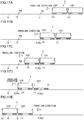
- Fig. 15 is a diagram schematically illustrating an example of the inclination information for each point for each axle and an example of a cant design value for each track for each point.
- standard deviations S1, S2...Sn indicate standard deviations of data of an axle in vertical one column (hereinafter, sometimes simply referred to as "column") of the same point
- standard deviations Z1, Z2... Z20 indicate standard deviations of horizontal one row (hereinafter, sometimes referred to simply as "row”) of the same axle.
- the determiner 44 determines the wheel state of the wheel 16 and the track state of the track 8 by using the inclination information (hereinafter, referred to as "a plurality of pieces of axle inclination information Mt" in the description of the present embodiment) on the plurality of axles acquired for the plurality of axles at a plurality of points, and provides the determination result E4.
- the determination result E4 includes the presence/absence of the wheel abnormality and the presence/absence of the track abnormality.
- the plurality of pieces of axle inclination information Mt includes inclination information Jm of axle number 1 described later and another axle inclination information Jr of axle number 2-20 described later.
- inclination information Jm, another axle inclination information Jr, and the plurality of pieces of axle inclination information Mt are collectively simply referred to as "inclination information”.
- Fig. 15 illustrates that a train having axles 16s of 20 axes (2 bogies per vehicle, 2 axes per bogie) in one organization of five trains acquires the plurality of pieces of axle inclination information Mt at n points.
- the plurality of axle inclination information Mt obtained for each axle 16s is indicated by data in one vertical one column of point number 1
- the inclination information acquired for each axle 16s is indicated by data in a vertical one column of the point number n.
- A1, A2... A20 are wheel components of the inclination caused by the wheel elements of each axle 16s
- B1, B2... Bn are the track components of the inclination caused by the track elements at each point.
- the plurality of pieces of axle inclination information Mt is acquired as the sum of the wheel component and the track component. Therefore, the wheel components A1, A2... A20 and the track components B1, B2... Bn cannot be individually acquired.
- the present inventors devise a method of estimating the wheel components A1, A2,... A20 using inclination components D1, D2,... Dn derived from a design value of the cant of the track at one or more of the measured n points. For example, in the region where the wear or deformation of the track is small and the unbalance of the track is small, the track components B1, B2... Bn are almost equal to the inclinations D1, D2... Dn. Therefore, the data calculated by subtracting the inclinations D1, D2... Dn from the plurality of pieces of axle inclination information Mt can be used as the wheel components A1, A2... A20. Note that instead of the design value of the cant, an inclination derived from a target value of the cant may be used.
- the determiner 44 determines that the wheel diameter difference is excessive and the wheels are abnormal, and when the calculated wheel components A1, A2... A20 is equal to or lower than the threshold, the determiner 44 determines that the wheel is not abnormal.
- the determination result E4 in this case is the presence or absence of the wheel abnormality.
- the wheel diameter difference of the axle is larger than that of other axles. For example, when the standardized result of dividing the deviation by the standard deviations S1, S2... Sn exceeds a preset threshold, it may be determined that the wheel diameter difference is excessive and the wheel is abnormal, and when the standardized result is equal to or lower than the threshold, it may be determined that the wheel is not abnormal.
- the track unbalance at the point is larger than that at other points. For example, when the standardized result of dividing the deviation by the standard deviations Z1, Z2... Z20 exceeds a preset threshold, it may be determined that the track unbalance is excessive and the track is abnormal, and when the standardized result is equal to or lower than the threshold, it may be determined that the track is not abnormal.
- the changes in the new data with respect to the past data are compared in each row, and when the change in a particular row is significantly larger than the changes in other rows, it can be determined that the wheel diameter difference of the axle corresponding to the particular row is excessive and the wheel is abnormal.
- the amount of change in the new data with respect to the past data is compared in each column, and when the amount of change in a particular column is significantly larger than the amount of change in other columns, it can be determined that the track is abnormal.
- the determination method of the determiner 44 described above can be variously modified.
- an example of determination based on the data of the plurality of pieces of axle inclination information Mt of a single train is shown, but for example, the wheel abnormality or the track abnormality may be determined based on the data of the plurality of pieces of axle inclination information at the same point of multiple trains. In this case, the number of data in each column increases and the determination accuracy improves.
- the determiner 44 may make the determination based on the inclination information and the vibration information Jv.
- characteristics of the vibration information Jv when the wheel diameter difference is large may be specified in advance and the determination may be made using the characteristics. For example, it may be determined that the wheel is abnormal when the characteristics of the vibration information Jv appear in the case where the wheel diameter difference is large regardless of the specific acquisition point (track position). Further, when the characteristics of the vibration information Jv appear only at a specific acquisition point (track position), it may be determined that the point is the track abnormality.
- the characteristics of the vibration information Jv include the frequency spectrum of the vibration and the amplitude fluctuation pattern of the vibration.
- the determiner 44 may determine the track abnormality based on the inclination information and the stroke information Jq.
- the stroke information Jq is acquired from the yaw damper stroke sensor 34. For example, for the stroke information Jq at the same acquisition point (track position), when the amount of change in newly acquired new data with respect to the past data previously acquired and stored exceeds a preset threshold, it may be determined that the track unbalance is excessive and the track is abnormal.
- the determiner 44 may determine the wheel state and the track state by using the learning model M4 generated in advance by machine learning.
- the learning model M4 can be generated by the machine learning (supervised learning) using the actual measurement data of the reference inclination information and the reference vibration information acquired in advance and the occurrence situation of the wheel abnormality or the track abnormality as the teacher data.
- the teacher data may include any one of the vibration level of the reference vibration information, the frequency spectrum of the vibration, and the amplitude fluctuation pattern of the vibration.
- the learning model M4 may be stored in the storage 46.
- the data of the inclination information has been shown as an example of being acquired while the vehicle is traveling, but it may be acquired while the vehicle is stopped at a station and the like, for example.
- the inclination information may be acquired when the vehicle speed detected by the speed sensor is zero.
- the inclination information may be acquired at any time, or may be acquired at a preset time such as the start of work or the end of work.
- the wheel diameter difference and the track unbalance increase as the wear and deformation progress according to the traveling distance of the bogie 10. If the wheel diameter difference becomes too large, it may interfere with traveling, and it is preferable to maintain the wheel 16 or the track 8 before interfering with the traveling. Therefore, the transmitter 48 notifies the determination result E4 to the outside.
- the inclination information may be the relative inclination with respect to a road surface.
- the inclination information can be acquired based on the difference between the measurement results (vertical distance) of the vertical distance between two points on a road surface or an object on the road surface by two distance sensors arranged spaced apart from each other in the front-back direction or in the width direction.
- the inclination information may be acquired from image data viewed from the direction of the axle 16s of the bogie 10 or the wheel 16 with a camera installed at a predetermined position such as before the vehicle base.
- the determination is made by referring to the inclination information of another axle, it can be determined that the wheel is abnormal when the difference between the plurality of axles is large. In the present embodiment, since the determination is made by referring to the inclination information of another point, it can be determined that the wheel is abnormal when the difference between the plurality of axles is large. In the present embodiment, since the determination is made by referring to the past inclination information previously acquired, it can be determined that the wheel is abnormal when the change over time is large.
- the determination is made by referring to the inclination information of another preceding or following vehicle, it can be determined that the wheel is abnormal when the difference between the plurality of vehicles is large.
- the determination is made by referring to the inclination information of the reference point for comparison, it can be determined that the wheel is abnormal when the difference with respect to the reference point is large.
- the determination is made by referring to the vibration information acquired by the vibration sensor, it can be determined that the wheel is abnormal when the characteristics of the vibration information appear in the case where the wheel diameter difference is large.
- track state As the railway vehicle travels, unevenness on a track surface increases due to wear, scratches, deformation, and the like, and the track deteriorates.
- track state As the railway vehicle travels, unevenness on a track surface increases due to wear, scratches, deformation, and the like, and the track deteriorates.
- track abnormality the preset standard
- the shaking of the bogie 10 becomes large and the ride comfort is reduced.
- track abnormality the deterioration in the track will progress further, which will hinder the operation of the vehicle. Therefore, it is important to detect the track abnormality early and perform the maintenance .
- the track abnormality is detected using the measurement data of the vibration of the bogie during the normal traveling of the vehicle 100.
- the vibration having a magnitude (hereinafter, referred to as "abnormal vibration" in the description of the present embodiment) exceeding a preset threshold.
- the abnormal vibration may occur due to temporary factors such as pinching foreign matter such as pebbles, in addition to the case of the track abnormality, so there is a possibility of erroneous determination. Therefore, in the present embodiment, the abnormal vibration due to the temporary factor is excluded and determined by using other vibration information acquired at another time.
- another time may be another time on the same day or may be another day.
- another vibration information may be acquired by the same bogie, another bogie, another vehicle, or another train.
- the condition monitoring device 20 includes an acquirer 30, an information processor 40, a power supplier 70, and a position information acquirer 82.
- the brake control device 80 includes the acquirer 30, the information processor 40, and a brake controller 60.
- the information processor 40 includes a determiner 44, a storage 46, a transmitter 48, and a transmission controller 42. Unless otherwise specified, the description of the first embodiment is applied to the configuration and operation of each of these elements.
- the acquirer 30 includes a vibration sensor 30b that acquires vibration information Jv on the vibration of the bogie 10. The acquirer 30 provides the information processor 40 with the vibration information Jv and acquisition information Jg described later as acquisition information J5.
- the information processor 40 acquires another bogie vibration information Jvb on vibration of another bogie 11 from another bogie vibration sensor 35 that acquires vibration information of the other bogie 11.
- the information processor 40 also acquires the position information Jp from the position information acquirer 82.
- the other bogie 11 may be another bogie of the vehicle 100 to which the bogie 10 belongs, or may be a bogie of another vehicle of another train to which the vehicle 100 belongs.
- Another bogie vibration sensor 35 may have the same configuration as the vibration sensor 30b, or may be attached to the other bogie 11 by the same attachment structure as the vibration sensor 30b.
- the other bogie 11 is a bogie of another vehicle 101 following the vehicle 100 in a train of a certain organization. Therefore, the bogie 10 passes the same point on the track 8 at a timing earlier than the other bogie 11.
- the bogie vibration sensor 35 different from the vibration sensor 30b of the present embodiment is provided in the axle box 14b.
- the determiner 44 determines the track state of the track 8 based on the vibration information Jv and the other bogie vibration information Jvb, and provides the determination result E5.
- the determination result E5 is the result of classifying the track state into a plurality of ranks according to the level.
- the determination result E5 may be the result of classifying the track state into two ranks, or may be the result of finer classifying the track state into three or more ranks.
- the determination result E5 of the present embodiment indicates whether or not there is the track abnormality of the track 8.
- the transmitter 48 transmits the determination result E5 of the determiner 44 to the outside of the bogie 10.
- the determination result E5 can be used externally.
- the transmitter 48 is provided on the bogie frame 12.
- the transmitter 48 may be provided on the vehicle body 2.
- the transmitter 48 transmits the determination result E5 to the cab 2d of the vehicle body 2.
- the determination result E5 may be displayed on a vehicle monitor 2e of the cab 2d.
- the transmitter 48 may transmit the determination result E5 to a computer 84c of a ground command station 84 outside the vehicle 100 or a cloud system. That is, the transmitter 48 can notify the determination result E5 to the outside of the bogie 10.
- the transmitter 48 transmits a brake control signal Bc to a brake controller 60 so as to adjust the braking force when the determination result E5 of the determiner 44 indicates the track abnormality.
- the brake controller 60 adjusts the braking force according to the brake control signal Bc transmitted from the transmitter 48.
- a first example of the determination method of the determiner 44 in the condition monitoring device 20 of the present embodiment configured as described above will be described.
- the vibration information Jv exceeds a preset threshold, it is determined that the abnormal vibration is observed and the track is abnormal.
- the vibration information Jv exceeds a preset threshold
- a second example of the determination method of the determiner 44 will be described with reference to Figs. 17A to 17E to 19 .
- the determination is performed by referring to another vibration information acquired at another time. Specifically, when it is evaluated that the track state is abnormal based on the vibration information at the same point and that the track state is abnormal based on another vibration information, the determiner 44 determines that there is the track abnormality at the point.
- another vibration information is acquired by performing measurement with the following another bogie 11.
- Figs. 17A to 17E are diagrams schematically illustrating a state in which the bogie 10 and the other bogie 11 are vibrated at points P and Q by an unevenness portion 8p on the track surface and a foreign matter 8q on the track surface.
- the bogie 10 is a bogie on a front side of preceding vehicle 100
- the other bogie 11 is a bogie on a front side of following another vehicle 101.
- the vehicle 100 and the other vehicle 101 are connected to constitute a train 3 of one organization.
- the unevenness portion 8p occurs by the deterioration in the track 8 and therefore is not lost even when the bogie 10 passes.
- the foreign matter 8q is a temporary one that is lost by the passage of the bogie 10.
- Fig. 18 is a diagram illustrating the vibration information Jv of the bogie 10 and another bogie vibration information Jvb of another bogie 11.
- a horizontal axis represents a position (hereinafter, referred to as "point" in the present embodiment) on the track, and a vertical axis represents a vibration level.
- the abnormal vibration is observed at points P and Q.
- the abnormal vibration is observed at the point P, but the abnormal vibration is not observed at the point Q.
- Fig. 19 is a flowchart illustrating an operation S120 of the condition monitoring device 20. The operation is executed while the train 3 is traveling. When the operation S120 is started, the abnormal vibration of the preceding bogie 10 is detected (step S121). In the example of Figs. 17A to 17E , the condition monitoring device 20 detects the abnormal vibration of the bogie 10 at the point P and the point Q.
- step S122 the abnormal vibration of the following another bogie 11 is detected.
- the condition monitoring device 20 detects the abnormal vibration of the other bogie 11 at the point P.
- condition monitoring device 20 determines whether the points of the abnormal vibration of bogie 10 and the abnormal vibration of the other bogie 11 match (step S123).
- the condition monitoring device 20 When the detection points of the abnormal vibration of the bogie 10 and the abnormal vibration of the other bogie 11 match (Y in step S123), the condition monitoring device 20 notifies the outside that the track abnormality has occurred (step S124).
- the abnormal vibrations of the bogie 10 and the other bogie 11 are detected together at the point P, so the condition monitoring device 20 transmits to the outside the fact that the track abnormality has occurred at point P as the determination result E5.
- condition monitoring device 20 ends operation S120.
- condition monitoring device 20 ends the operation S120 after executing step S124.
- This operation S120 is merely an example, and the order of steps may be changed, or some steps may be added/deleted/changed.
- the determination method of the determiner 44 described above can be variously modified.
- an example of determination based on the data of the vibration information of the plurality of bogies of a single train is shown, but for example, the track abnormality may be determined based on the data of the vibration information at the same point of multiple trains.
- the characteristics of the vibration information Jv may be used for the determination.
- the characteristics of the vibration information Jv when there is the track abnormality may be stored in advance, and it may be determined that the point where the characteristics appear in the data of the actually measured vibration information Jv is the track abnormality.
- examples of the characteristics of the vibration information Jv include a frequency spectrum (hereinafter referred to as" spectrum" in the description of the present embodiment) of the vibration information Jv, an amplitude variation pattern, and the like.
- the spectrum is obtained by performing Fourier transform a time domain waveform of data and transforming the time domain waveform into a frequency domain.
- a learning model is generated by the machine learning using the track state at the time of the past track abnormality occurrence and the spectrum of the past actual measurement data as the teacher data, and the spectrum of new actual measurement data is input to the learning model, thereby understanding the track state.
- the determiner 44 may determine the track state by using the learning model M5 generated in advance by the machine learning.
- the learning model M5 can be generated by the machine learning (supervised learning) using the actual measurement data of the reference inclination information acquired in advance and the occurrence situation of the track abnormality as the teacher data.
- the teacher data may include any one of the vibration level of the reference vibration information, the spectrum of the vibration, and the amplitude fluctuation pattern of the vibration.
- the learning model M5 may be stored in the storage 46.
- the bogie frame 12 of the bogie 10 may be provided with the image sensor 30g that acquires the image of the track surface and outputs the image information Jg, and the determiner 44 may determine the track state based on the image information Jg acquired by the image sensor 30g. For example, when an image different from the images before and after the imaged area appears in the image information Jg on the track surface, it may be determined that the image is abnormal and the track is abnormal. In this case, it may be possible to make the erroneous determination due to the temporary factor, so it is preferable to perform the remeasurement at the same point or perform the reconfirmation by the visual observation.
- the determination is performed by referring to another vibration information acquired at another time.
- another image sensor is installed at another position away in the traveling direction of the train, and when the determination point of the image abnormality based on the image information of the image sensor 30g and the determination point of the image abnormality based on another image sensor match each other, it may be determined that the track is abnormal.
- the determiner 44 may determine that there is the track abnormality at the point.
- the image sensor 30g may be arranged in a middle bogie avoiding the head bogie or the tail bogie. Further, in order to reduce the influence of the incident amount of the external light, a plurality of image sensors 30g may be provided, and the determination may be made using the image information acquired by the image sensor 30g having the smaller incident amount of the external light. In addition, a light irradiator 32 that illuminates the track 8 may be provided to obtain good image information.
- condition monitoring device 20 determines the track state based on the vibration or image information acquired while traveling, the track state can be understood with a small number of man-hours, which is advantageous in terms of cost.
- the track state is determined by referring to another information acquired at another time with respect to the same point on the track 8, so the erroneous determination due to the temporary factor can be prevented.
- the determination result of the determiner is notified to the outside of the bogie, so the determination result can be used for early maintenance.
- the directly acquired information can be used.
- another information is acquired by the sensor provided in another bogie of another vehicle in the same train, so the system can be completed in the train.
- the acquirer 30 is attached to the bogie frame 12 or the unsprung part 14, and the determiner 44 is attached to the bogie frame 12, so the wiring distance between the acquirer 30 and the determiner 44 can be shortened.
- a brake 18 of a vehicle 100 is stopped within a predetermined braking distance by assigning a required braking force to a regenerative brake 18e and a contact brake 18d.
- the contact brake 18d presses a brake shoe 18b against a tread surface 16b of the wheel 16 to generate a frictional force therebetween, and decelerates and stops the vehicle 100 by the frictional force.
- a smooth state of the tread surface 16b is smoother than a preset reference (hereinafter, referred to as "oversmooth state" in the description of the present embodiment)
- sufficient frictional force cannot be obtained and thus a braking distance becomes long. It is important to detect and cope with the oversmooth state because the vehicle operation is hindered due to overrun and the like when the braking distance becomes long.
- the oversmooth state occurs, for example, when the surface roughness of the tread surface 16b is excessively small and when the surface of the tread surface 16b is mirror-finished even when the surface roughness is above a certain level. Therefore, the oversmooth state of the present embodiment includes a mirror surface state, and includes a state that is not a mirror surface but has an excessively small surface roughness.
- tread surface information J6 tread surface information
- the optical sensor 30f irradiates a laser on the tread surface 16b from the light irradiator 32 provided on the bogie 10 and acquires the reflected light.
- the tread surface 16b is roughened and is not oversmooth (hereinafter, referred to as "non-oversmooth state in the description of the present embodiment) . Therefore, if it is determined that the tread surface 16b is in the oversmooth state, the tread surface 16b can be roughened and the frictional force can be recovered by controlling the pressing force of the brake shoe 18b to be large.
- the condition monitoring device 20 includes an acquirer 30, an information processor 40, a brake controller 60, a power supplier 70, a position information acquirer 82, a speed sensor 30c, and a light irradiator 32.
- the brake control device 80 includes the acquirer 30, the information processor 40, and a brake controller 60.
- the information processor 40 includes a determiner 44, a storage 46, a transmitter 48, and a transmission controller 42. Unless otherwise specified, the description of the first embodiment is applied to the configuration and operation of each of these elements.
- the information processor 40 acquires speed information Jc from the speed sensor 30c and position information Jp from the position information acquirer 82.
- the acquirer 30 includes an optical sensor 30f that acquires tread surface information J6 on a surface texture of the tread surface 16b in the bogie 10.
- the acquirer 30 provides the tread surface information J6 to the information processor 40.
- the storage 46 temporarily stores the tread surface information J6 acquired by the acquirer 30.
- the storage 46 can store the tread surface information J6 in association with the speed information Jc at the time of the acquisition.
- the storage 46 can store the tread surface information J6 in association with the speed information Jc at the time of the acquisition.
- the storage 46 can store the tread surface information J6 in association with the acquired position information Jp of the point on the track.
- the determiner 44 determines the smooth state of the tread surface 16b based on the tread surface information J6 acquired by the acquirer 30, and provides the determination result E6.
- the determination result E6 is the result of classifying the smooth state into a plurality of ranks according to the level.
- the determination result E6 may be the result of classifying the smooth state into two ranks, or may be the result of finer classifying the smooth state into three or more ranks.
- the determination result E6 of the present embodiment indicates whether the tread surface 16b is in the oversmooth state
- the transmitter 48 transmits the determination result E6 of the determiner 44 to the outside of the bogie 10.
- the determination result E6 can be used externally.
- the transmitter 48 is provided on the bogie frame 12.
- the transmitter 48 may be provided on the vehicle body 2.
- the transmitter 48 transmits the determination result E6 to the cab 2d of the vehicle body 2.
- the determination result E6 may be displayed on a vehicle monitor 2e of the cab 2d.
- the transmitter 48 may transmit the determination result E6 to a computer 84c of a ground command station 84 outside the vehicle 100 or a cloud system. That is, the transmitter 48 can notify the determination result E6 to the outside of the bogie 10.
- the transmitter 48 transmits a brake control signal Bc to a brake controller 60 so as to adjust the braking force when the determination result E6 of the determiner 44 is in the oversmooth state.
- the brake controller 60 adjusts the braking force according to the brake control signal Bc transmitted from the transmitter 48.
- the acquirer 30, the information processor 40, and the brake controller 60 constitutes the brake control device 80. The operation of the brake control device 80 will be described later.
- the acquirer 30 is attached to the bogie 10.
- the tread surface information J6 can be acquired with high accuracy by keeping the positional relationship between the acquirer 30 and the wheels 16 constant.
- the determiner 44 and the brake controller 60 are provided on the bogie 10 or the vehicle body 2. In this case, since the determiner 44 and the brake controller 60 can be arranged in a location where vibration is small, the influence due to the vibration can be mitigated.
- the determiner 44 determines that the tread surface 16b is in the oversmooth state when the smooth state of the tread surface 16b indicated by the tread surface information J6 acquired by the acquirer 30 is smoother than a preset reference. Further, when the smooth state is not smoother than the reference, the tread surface 16b is determined to be in a non-oversmooth state (not an oversmooth state). The determiner 44 provides the determination result E6.
- Fig. 21 is a flowchart illustrating an operation S130 of the brake control device 80.
- Fig. 22 is a diagram illustrating an example of the ratio of the braking force of the contact brake 18d to the braking force of the brake 18.
- Graph A in Fig. 22 illustrates the ratio of the braking force (for example, 30%) of the contact brake 18d when the desired braking force of the brake 18 is 100% during normal operation (during non-brake control).
- Graph B shows the ratio (for example, 40%) of the braking force of the contact brake 18d during the roughening operation (during brake control).
- Figs. 23 and 24 are diagrams schematically illustrating the operation of the contact brake 18d.
- This operation is performed while the vehicle 100 is traveling and the brake 18 is operating.
- the operation S130 is started, it is determined whether the regenerative brake 18e is operating (step S131) .
- the brake controller 60 ends the operation S130. That is, when 100% of the braking force of the brake 18 is the braking force of the contact brake 18d, the brake control is not executed. This is because if the braking force of the contact brake 18d is too strong, the vehicle may slip.
- step S131 When the regenerative brake 18e is operating (Y in step S131), the determiner 44 determines whether the tread surface 16b is in the oversmooth state (step S132). In this step, the determiner 44 provides the determination result E6 to the brake controller 60 by the above operation.
- condition monitoring device 20 may notify the outside that the oversmooth state has occurred.
- step S134 After executing step S134, the process is returned to the beginning of step S131, and the loop of steps S131 to S134 is repeated. The determination of the tread surface 16b is continued while this loop is repeated including the execution of step S134.
- the brake controller 60 reduces the braking force of the contact brake 18d and returns to the braking force during normal operation, and the operation S130 is ended. At this time, the ratio of the braking force of the contact brake 18d decreases to the ratio during normal operation.
- This operation S130 is merely an example, and the order of steps may be changed, or some steps may be added/deleted/changed.
- the determiner 44 may determine the smooth state of the tread surface 16b by using the learning model M6 generated in advance by the machine learning.
- the learning model M6 can be generated by machine learning (supervised learning) using, as teacher data, the fluctuation pattern of the tread surface information J6 when the past oversmooth state occurs.
- the learning model M6 may be stored in the storage 46.
- the brake controller 60 may advance the operation start timing of the contact brake 18d. By advancing the operation timing of the contact brake 18d, the time when the brake shoe 18b is in contact with the tread surface 16b becomes longer and the roughening of the tread surface 16b can be promoted.
- the brake controller 60 may change the ratio of the braking force of the contact brake 18d or the operation timing of the contact brake 18d and the regenerative brake 18e by referring to the speed (speed information Jc) of the vehicle 100.
- condition monitoring device 20 determines the smooth state of the tread surface 16b based on the tread surface information J6 regarding the surface texture of the tread surface 16b, the smooth state of the tread surface 16b can be understood with a small number of man-hours, which is advantageous in terms of cost.
- the tread surface 16b can be roughened to recover the braking force.
- the braking force of the contact brake 18d decreases when the smooth state is not smoother than the reference, so the balance with the braking force of the regenerative brake 18e returns to a normal state.
- the detection result of the optical sensor 30f or the imaging result of the image sensor 30g is provided as the tread surface information J6, it is advantageous for miniaturization at low cost.
- the braking force or the operation timing of the contact brake 18d changes by referring to the vehicle speed, more appropriate control can be performed according to the vehicle speed.
- FIG. 25 is a block diagram schematically illustrating a condition monitoring device 20 and a brake control device 80 according to the present embodiment.
- overwear If a track is excessively worn (hereinafter, referred to as "overwear” in the present embodiment), the ride comfort becomes poor. Therefore, it is important to specify a wear position of the track and perform maintenance. It is possible to use a dedicated track inspection car to detect the wear of the track, but in this case, the track inspection car is expensive and also requires extra man-hours. For this reason, it is important to monitor the worn state so as not to excessively wear the track.
- a condition monitoring device 20 of the present embodiment is an acquirer 30 that acquires information (hereinafter, referred to as "track information J7") on the wear of the track 8 on which the railway vehicle 100 travels and a transmitter 48 that transmits track information J7 acquired by the acquirer 30.
- track information J7 information
- the worn state of the track 8 can be monitored based on track information J7.
- a braking start position (hereinafter, simply referred to as a "braking start position" in the present embodiment) of a contact brake 18d, and when the braking start position is concentrated at the same position, the wear was likely to proceed at that position.
- a braking start position hereinafter, simply referred to as a "braking start position" in the present embodiment
- the wear was likely to proceed at that position.
- the track information Jx includes information on a certain amount of wear (hereinafter, referred to as “specific wear” in the present embodiment) and the position (hereinafter, referred to as “specific position” in the present embodiment) of the specific wear on track 8. Note that the specific wear includes overwear and wear that is not overwear but proceeds above a certain level.
- the braking start position of the contact brake 18d can be dispersed in the front-back direction of the specific position, and the wear of the track 8 can be dispersed.
- the braking start position of the contact brake 18d can be set while avoiding a specific position. By distributing the wear position, the frequency of replacing the track 8 can be reduced.
- the track information providing device 90 is not limited as long as it can provide the track information Jx, and examples thereof include the following.
- the track information providing device 90 includes an image sensor 90g, a position information acquirer 90p, a wear determiner 90j, and an information transmitter 90x.
- the image sensor 90g images the preceding position of the track 8 and acquires the image information.
- the image sensor 90g is provided in the bogie of the preceding vehicle and acquires image information on the worn state of the track 8 from the reflected light of the light irradiated to the track 8.
- This image information may be a still image or a moving image.
- the configuration of the image sensor 90g is the same as that of the image sensor 30g of the first embodiment.
- the position information acquirer 90p acquires position information on the position of the track information providing device 90 (preceding vehicle).
- the configuration of the position information acquirer 90p is the same as that of the position information acquirer 82 of the first embodiment.
- the information transmitter 90x transmits the track information Jx at the position (specific position) where the specific wear is detected when there is specific wear.
- the information transmitter 90x transmits the track information Jx when there is a request from another vehicle such as a following vehicle, the ground command station 84, or other outside.
- the information transmitter 90x may autonomously transmit the track information Jx even when there is no request from the outside.
- the information acquirer 30x receives the track information Jx transmitted from the track information providing device 90 and provides the received track information Jx to the information processor 40.
- the information acquirer 30x may request the track information providing device 90 to transmit the track information Jx.
- the position information acquirer 82 provides the position information Jp to the information processor 40.
- the acquirer 30 is provided in the bogie 10 and includes an image sensor 30g that acquires track information J7 on the wear of the track 8.
- the acquirer 30 provides the track information J7 to the information processor 40.
- the storage 46 temporarily stores the track information J7 acquired by the acquirer 30.
- the storage 46 can store the track information J7 in association with the acquisition timing.
- the storage 46 can store the acquired track information J7 in association with the position information Jp of the position on the track.
- the storage 46 temporarily stores the information on the specific wear of the track information Jx in association with the specific position.
- the determiner 44 determines whether or not the track 8 on the track of the vehicle 100 has the specific wear based on the track information Jx transmitted from the track information providing device 90 (preceding vehicle). Specifically, the determiner 44 determines whether or not the specific position of the track information Jx exists on the route of the vehicle 100, and provides the determination result E7. Therefore, the determination result E7 of the present embodiment indicates whether or not there is specific wear on the track.
- the transmitter 48 transmits the determination result E7 of the determiner 44 to the outside of the bogie 10.
- the determination result E7 can be used externally.
- the transmitter 48 is provided on the bogie frame 12.
- the transmitter 48 may be provided on the vehicle body 2.
- the transmitter 48 transmits the determination result E7 to the cab 2d of the vehicle body 2.
- the determination result E7 may be displayed on a vehicle monitor 2e of the cab 2d.
- the transmitter 48 may transmit the determination result E7 to a computer 84c of a ground command station 84 outside the vehicle 100 or a cloud system. That is, the transmitter 48 can notify the determination result E7 to the outside of the bogie 10.
- the transmitter 48 transmits a brake control signal Bc to a brake controller 60 so as to control a braking start position when the determination result E7 of the determiner 44 indicates that there is the specific wear.
- the brake controller 60 controls the braking start position according to the brake control signal Bc transmitted from the transmitter 48. The operation of the brake control device 80 will be described later.
- the determiner 44 and the brake controller 60 are provided on the bogie 10 or the vehicle body 2. In this case, since the determiner 44 and the brake controller 60 can be arranged in a location where vibration is small, the influence due to the vibration can be mitigated.
- the determiner 44 determines whether there is the specific wear from the track information J7 acquired by the image sensor 30g of the acquirer 30.
- the determiner 44 specifies the specific position from the position information Jp of the position information acquirer 82.
- the transmitter 48 transmits the information of the specific wear and the specific position to the outside. That is, the condition monitoring device 20 may function as the track information providing device 90 (preceding vehicle) for the following vehicle, and may apply the description of the track information providing device 90.
- Fig. 26 is a flowchart illustrating an operation S140 of the brake control device 80.
- Figs. 27A and 27B are diagrams schematically illustrating an operation S140 of the brake control device 80. This operation is an operation for controlling the braking start position.
- the "braking" in the description of the operation S140 indicates braking by the contact brake 18d unless otherwise specified.
- the track information providing device 90 is another preceding vehicle 101. The operation is executed while the vehicle 100 is traveling.
- Fig. 27A illustrates a case where specific wear 8d exists on the track 8 and another vehicle 101 preceding this track 8 and a vehicle 100 following another vehicle 101 travel in the traveling direction.
- the other vehicle 101 detects the specific wear 8d
- the other vehicle 101 transmits the track information Jx at the position (specific position) where the specific wear 8d is detected.
- the vehicle 100 receives the track information Jx.
- the vehicle 100 starts braking at a preset position T as illustrated in a first pattern of Figs. 27A and 27B .
- the set position T is the same every time, and there is a possibility that the specific wear will occur at this position.
- the set position T is stored in the storage 46.
- the determiner 44 determines whether or not the specific wear 8d exists at the track 8 on the route has the specific wear 8d (step S141). In this step, the determiner 44 makes a determination based on the presence or absence of the specific wear 8d of the track information Jx transmitted from the track information providing device 90 (another preceding vehicle 101). When there is no specific wear 8d (N in step S141), the brake controller 60 ends the operation S140.
- the brake controller 60 determines whether the specific position where the specific wear 8d is present is the set position T of the vehicle 100 (step S142) . When the specific position is not the set position T (N in step S142), the brake controller 60 ends the operation S140.
- the brake controller 60 determines whether the vehicle 100 can be stopped within the allowable stop range without using excessive braking when the braking is started at a position (delay position) posterior to the specific position (step S143) . For example, it can be determined that the vehicle can be stopped when the braking distance by the normal braking is shorter than the distance to the allowable vehicle stop range.
- step S143 the brake controller 60 starts braking after the vehicle 100 passes the specific position, as illustrated in a second pattern of Figs. 27A and 27B (step S144) . After executing step S144, the brake controller 60 ends the operation S140.
- step S143 When the vehicle 100 cannot stop within the allowable stop range (N in step S143), the brake controller 60 starts braking at a position (early position) before the specific position, as illustrated in a third pattern of Figs. 27A and 27B (step S145).
- step S146 the brake controller 60 determines whether the vehicle 100 has reached a specific position. When the vehicle 100 does not reach the specific position (N in step S146), the brake controller 60 returns the process to the beginning of step S145 and maintains the braking state.
- the brake controller 60 stops braking (step S147) .
- the braking stop in this case includes a braking stop in a narrow sense and a substantial braking stop that slightly causes a braking force.
- step S148 the brake controller 60 determines whether the vehicle 100 passes through the specific position.
- the brake controller 60 returns the process to the beginning of step S147 and maintains the braking stop state.
- step S149 the brake controller 60 resumes the braking (step S149).
- step S149 the brake controller 60 ends the operation S140.
- This operation S140 is merely an example, and the order of steps may be changed, or some steps may be added/deleted/changed.
- the braking start position can be dispersed before and after the specific position. By doing so, the progress of wear is delayed and the frequency of replacing track is reduced.
- the operation of the brake control device 80 can be variously modified.
- the determination in step S143 may be performed using a learning model M7 generated in advance by machine learning.
- the learning model M7 can be generated by machine learning (supervised learning) using the past actual measurement data of the vehicle speed, the braking start position, and the braking distance as teacher data.
- the learning model M7 may be stored in the storage 46.
- the operation of the brake control device 80 is particularly effective for vehicles that are automatically operated, but can also be applied to non-automatically operated vehicles that are driven by a driver.
- a notifier (not illustrated) for notifying the driver of the braking start position may be provided.
- the driver can activate the contact brake 18d at the notification timing of the notifier.
- the acquirer 30 includes an image sensor attached to the bogie 10 of the vehicle 100.
- the acquirer 30 may include a strain sensor that acquires strain information on the strain of the track 8. In this case, it is possible to disperse the braking start positions based on the strain of the track 8 and make the wear uniform.
- FIG. 28 is a block diagram schematically illustrating a condition monitoring device 20 and a brake control device 80 according to the present embodiment.
- a brake receiver is used to control a regenerative brake and a contact brake according to the vehicle weight. Therefore, it is important to understand the vehicle weight with high accuracy.
- an air spring 12s arranged between the bogie 10 and the vehicle body 2 to calculate the vehicle weight based on a displacement of the air spring 12s and a spring constant.
- the spring constant becomes non-linear and the error becomes large because a dead zone of a leveling valve, rattling of a link device for detection, and the like exist in the air spring 12s.
- the present inventors devised a technique for calculating the vehicle weight based on the displacement of the shaft spring 12j and the spring constant by focusing on the shaft spring 12j arranged between the bogie frame 12 and the unsprung part 14.
- the condition monitoring device 20 of the present embodiment is an acquirer 30 that acquires information (hereinafter, referred to as "distance information J8" in this specification) on a distance between the bogie 10 of the railway vehicle 100 on the track 8 and the track 8 and a determiner 44 that determines the weight of the vehicle 100 based on the distance information J8 acquired by the acquirer 30.
- the vehicle weight of the track 8 can be monitored based on the distance information J8.
- This technology can improve the calculation accuracy of the vehicle weight compared to the case of using the air spring 12s.
- this technology can also be applied to vehicles that do not have air springs.
- Fig. 29 is a diagram schematically illustrating the bogie 10 viewed from the front.
- Fig. 30 is a diagram schematically illustrating the bogie 10 viewed from the side.
- the acquirer 30 is attached to the bogie frame 12 of the bogie 10 and includes a plurality of distance sensors 30ka and 30kb for measuring the distances to the tracks 8 on both sides in the width direction. Since the plurality of distance sensors 30ka and 30kb are used, the error when the weight balance of the vehicle body 2 is biased to one side in the width direction can be reduced.
- the distance sensors 30ka and 30kb of the present embodiment are each attached to the lower surfaces of the side beams 12e and 12f on both sides in the width direction, respectively.
- a distance sensor 30ka measures a distance Hka to an upper surface (tread surface) of the track 8 on a lower surface of one side beam 12e
- a distance sensor 30kb measures a distance Hkb to the upper surface (tread surface) of the track 8 on a lower surface of the other side beam 12f.
- the distance sensors 30ka and 30kb are laser displacement sensors that acquire a separation distance based on the reflected light of the irradiated laser.
- the distance sensors 30ka and 30kb may be the known sensors such as ultrasonic sensors and optical sensors instead of the laser displacement sensor.
- the measurement results of the distances Hka and Hkb are provided as the distance information J8.
- the plurality of distance sensors 30ka and 30kb measure the distance to the track at a central position between the front and rear wheels of the bogie 10.
- the central position is not limited to the strict central position, and includes the case where the central position can be visually determined. Since the distance is measured at the central position, the error when the weight balance of the vehicle body 2 is biased to the front or rear can be reduced. Further, in this case, since the distance measurement is performed at a position away from the wheel, the influence by a state of a contact surface between the wheel 16 and the track 8 can be reduced. Note that the distance sensors 30ka and 30kb may be arranged at positions deviated from the central position to the front and rear.
- side beams 12e and 12f have central portions located below both ends in the front-back direction.
- the distance sensors 30ka and 30kb may be provided at a portion located below the front and rear ends of the side beams 12e and 12f, or may be provided at a portion closest to the track 8.
- the present embodiment includes the transmitter 48 that transmits a determination result E8 of the determiner 44 to the outside of the bogie 10.
- the transmitter 48 functions as a notifier that notifies the determination result E8 to the outside.
- the present embodiment includes the brake control device 80 that changes how to apply the brake 18 according to the determination result E8 of the vehicle weight, as illustrated in Fig. 28 .
- the brake control device 80 includes the acquirer 30 that acquires the distance information J8 on the distance between the bogie 10 of the railway vehicle 100 on the track 8 and the track 8, the determiner 44 that determines the weight of the vehicle 100 based on the distance information J8 acquired by the acquirer 30, and the brake controller 60 that changes the braking force or the operation timing of the brake 18 of the vehicle 100 based on the determination result E8 of the determiner 44.
- the method of applying the brake 18 can be changed according to the distance information J8.
- the control operation of the brake will be described later.
- the condition monitoring device 20 includes the acquirer 30, the information processor 40, the power supplier 70, and the position information acquirer 82.
- the brake control device 80 includes the acquirer 30, the information processor 40, the determiner 44, and the brake controller 60.
- the information processor 40 includes the storage 46, the transmitter 48, and the transmission controller 42. Unless otherwise specified, the description of the first embodiment is applied to the configuration and operation of each of these elements.
- the position information acquirer 82 provides the position information Jp to the information processor 40.
- the acquirer 30 is provided on the bogie frame 12 of the bogie 10 and provides the distance information J8 including the distances Hka and Hkb to the information processor 40.
- the storage 46 temporarily stores the distance information J8 acquired by the acquirer 30.
- the storage 46 can store the distance information J8 in association with the acquisition timing.
- the storage 46 can store the distance information J8 in association with the acquired position information Jp of the position on the track.
- the storage 46 can store the past data previously acquired, the initial data at the time of manufacturing or maintenance, and the design data on the design, regarding the distance information J8.
- the determiner 44 determines the vehicle weight based on the distance information J8 acquired by the acquirer 30 and provides the determination result E8. Specifically, the determiner 44 determines the vehicle weight calculated from the distance information J8 using a preset threshold.
- the determination result E8 is a result of classifying the calculated vehicle weight into a plurality of ranks according to the level. For example, the determination result E8 may be a result of classifying the distance information J8 into two ranks, or may be a result of finer classifying the distance information into three or more ranks.
- the determination result E8 of the present embodiment indicates whether or not the vehicle weight is greater than the threshold.
- parameters for the vehicle weight of the power running control and the brake control may be automatically changed according to the vehicle weight without dividing the vehicle weight into ranks.
- the vehicle weight may be input to the brake receiver that performs control so as to exert a constant deceleration according to the brake command.
- the brake receiver controls the regenerative brake and contact brake according to the vehicle weight.
- the transmitter 48 transmits the determination result E8 of the determiner 44 to the outside of the bogie 10.
- the determination result E8 can be used externally.
- the transmitter 48 is provided on the bogie frame 12.
- the transmitter 48 may be provided on the vehicle body 2.
- the transmitter 48 transmits the determination result E8 to the cab 2d of the vehicle body 2.
- the transmitter 48 may transmit the determination result E8 to a computer 84c of a ground command station 84 outside the vehicle 100 or a cloud system. That is, the transmitter 48 can notify the determination result E8 to the outside of the bogie 10.
- the determiner 44 and the brake controller 60 are provided on the bogie 10 or the vehicle body 2. In this case, since the determiner 44 and the brake controller 60 can be arranged in a location where vibration is small, the influence due to the vibration can be mitigated.
- the operation of the condition monitoring device 20 may be executed while the vehicle 100 is stopped or traveling.
- the value for example, the average value obtained by statistically processing the data acquired during at least one rotation of the wheel 16 is used as the distance information J8. In this case, the influence of the local wear of the wheels 16 can be suppressed.
- the brake control device 80 inputs the calculated vehicle weight to the brake receiver, and calculates the required braking force according to the vehicle weight. In addition, the brake control device 80 transmits the calculated vehicle weight to the outside and performs the power running control and the braking control of the vehicle with the vehicle weight as a control parameter. The operation of the brake control device 80 may be executed at regular intervals.
- the relationship between the displacement of the shaft spring 12j and the vehicle weight is non-linear, and it may be difficult to calculate the vehicle weight from the detection results of the distance sensors 30ka and 30kb.
- the vehicle weight may be calculated using a learning model M8 generated in advance by machine learning.
- the learning model M8 can be generated by machine learning (supervised learning) using the detection results of the distance sensors 30ka and 30kb and the past actual measurement data of the vehicle weight as teacher data.
- the learning model M8 may be stored in the storage 46.
- FIG. 31 is a block diagram schematically illustrating a condition monitoring device 20 and a brake control device 80 according to the present embodiment.
- a diameter (hereinafter, referred to as" wheel diameter" in the present embodiment) of the tread surface 16b of the wheel 16 is set as an important parameter in the power running control and the brake control of the vehicle 100. Therefore, it is desirable to understand the wheel diameter and change parameters according to the amount of change in the wheel diameter before the wheel diameter changes excessively.
- the amount of change in a wheel shape in the present embodiment
- the method requires complicated calculations to improve the measurement accuracy, and is disadvantageous in terms of cost due to the use of a large-scale dedicated device.
- the present inventors proposed a technique for calculating the wheel shape change amount from the change amount of the newly measured distance between the bogie 10 and track 8 with respect to the reference distance between the bogie 10 and the track 8.
- the condition monitoring device 20 of the present embodiment is an acquirer 30 that acquires information (hereinafter, referred to as "distance information J9" in this specification) on a distance between the bogie 10 of the railway vehicle 100 on the track 8 and the track 8 and a determiner 44 that determines the shape change amount of the wheel 16 of the bogie 10 based on the distance information J9 acquired by the acquirer 30 and the preset reference distance information Js.
- distance information J9 information on a distance between the bogie 10 of the railway vehicle 100 on the track 8 and the track 8
- determiner 44 that determines the shape change amount of the wheel 16 of the bogie 10 based on the distance information J9 acquired by the acquirer 30 and the preset reference distance information Js.
- the wheel shape change amount of the track 8 can be monitored based on the distance information J9.
- Fig. 32 is a diagram schematically illustrating the bogie 10 viewed from the front.
- Fig. 33 is a diagram schematically illustrating the bogie 10 viewed from one side.
- Fig. 34 is a diagram schematically illustrating the bogie 10 viewed from the other side.
- the acquirer 30 is attached to the bogie frame 12 of the bogie 10 and is arranged spaced apart from each other on both sides in the width direction, and includes a first distance sensor 30p and a second distance sensor 30s each measuring a distance to the track 8.
- the first distance sensor 30p and the second distance sensor 30s arranged spaced apart from each other on both sides in the width direction are used, the error when the weight balance of the vehicle body 2 is biased to one side in the width direction can be reduced.
- the first distance sensor 30p and the second distance sensor 30s of the present embodiment are each attached to lower surfaces of side beams 12e and 12f on both sides in the width direction, respectively.
- the first distance sensor 30p includes a plurality (two) of sensor units 30pa and 30pb which are arranged spaced apart from each other in the front-rear direction between the front wheel 16f and the rear wheel 16r of the bogie 10.
- the sensor units 30pa and 30pb measure distances Hpa and Hpb to the upper surface (tread surface) of the track 8 on the lower surface of the one side beam 12e.
- the second distance sensor 30s includes a plurality (two) of sensor units 30sa and 30sb which are arranged spaced apart from each other in the front-rear direction between the front wheel 16f and the rear wheel 16r of the bogie 10.
- the sensor units 30sa and 30sb measure distances Hsa and Hsb to the upper surface (tread surface) of the track 8 on the lower surface of the other side beam 12f.
- the sensor units 30pa, 30pb, 30sa, and 30sb are laser displacement sensors that acquire a separation distance based on the reflected light of the irradiated laser.
- the sensor units 30pa, 30pb, 30sa, and 30sb may be the known sensors such as ultrasonic sensors and optical sensors instead of the laser displacement sensor.
- the measurement results of the distances Hpa, Hpb, Hsa, and Hsb are provided as the distance information J9.
- the sensor units 30pa and 30sa are arranged closer to the front wheel 16f with respect to the central position of the bogie 10, and the sensor units 30pb and 30sb are arranged closer to the rear wheel 16r respect to the central position of the bogie 10.
- the sensor unit corresponding to each of the four wheels 16 the wheel shape change amount of each of the four wheels 16 can be measured.
- the measurement error of the wheel shape change amount can be reduced.
- side beams 12e and 12f have a middle portion located below both ends in the front-back direction.
- the sensor units 30pa, 30pb, 30sa, and 30sb may be provided at a portion located below the front and rear ends of the side beams 12e and 12f, or may be provided at a portion closest to the track 8.
- the condition monitoring device 20 includes the acquirer 30, the information processor 40, the power supplier 70, and the position information acquirer 82.
- the brake control device 80 includes the acquirer 30, the information processor 40, and a brake controller 60.
- the information processor 40 includes a determiner 44, a storage 46, a transmitter 48, and a transmission controller 42. Unless otherwise specified, the description of the first embodiment is applied to the configuration and operation of each of these elements.
- the position information acquirer 82 provides the position information Jp to the information processor 40.
- the acquirer 30 is provided on the bogie frame 12 of the bogie 10 and provides the distance information J9 including the distances Hpa, Hpb, Hsa, and Hsb to the information processor 40.
- the storage 46 temporarily stores the distance information J9 acquired by the acquirer 30.
- the storage 46 can store the distance information J9 in association with the acquisition timing.
- the storage 46 can store the distance information J9 in association with the acquired position information Jp of the position on the track.
- the storage 46 can store the past data previously acquired, the initial data at the time of manufacturing or maintenance, and the design data on the design, as the reference distance information Js.
- the determination result E9 of the present embodiment is a result of classifying the wear amount of the wheel shape change amount into three ranks of "low wear amount", “medium wear amount ", and "large wear amount”. For example, when the determination result E9 indicates the "low wear amount”, it can be predicted that the maintenance time will not be reached for the time being. For example, when the determination result E9 indicates the " medium wear amount”, it can be predicted that the maintenance time such as the wheel rolling is reached after half a year. For example, when the determination result E9 indicates the "large wear amount”, it can be predicted that the maintenance time such as the wheel rolling is reached within three months.
- the determination result E9 of the present embodiment is a result of classifying the wheel diameter change amount of the wheel shape change amount into three ranks of "low change amount”, “medium change amount”, and "large change amount”. For example, when the determination result E9 indicates that the wheel diameter is the “medium change amount” or the "large change amount ", parameters for the power running control and the brake control of the vehicle 100 may be changed according to the change amount.
- the parameters for the wheel diameter of the power running control and the brake control may be automatically changed according to the wheel diameter change amount without classifying the ranks.
- the wheel change amount may be input to the brake receiver that performs control so as to exert a constant deceleration according to the brake command.
- the brake receiver controls the regenerative brake and contact brake according to the vehicle diameter change amount.
- the transmitter 48 transmits the determination result E9 of the determiner 44 to the outside of the bogie 10.
- the determination result E9 can be used externally.
- the transmitter 48 is provided on the bogie frame 12.
- the transmitter 48 may be provided on the vehicle body 2.
- the transmitter 48 transmits the determination result E9 to the cab 2d of the vehicle body 2.
- the transmitter 48 may transmit the determination result E9 to a computer 84c of a ground command station 84 outside the vehicle 100 or a cloud system. That is, the transmitter 48 can notify the determination result E9 to the outside of the bogie 10.
- the transmitter 48 transmits the brake control signal Bc to the brake controller 60 when the determination result E9 of the determiner 44 indicates that the wheel diameter is the " medium change amount” or the "large change amount”.
- the brake controller 60 controls to increase the braking force of the contact brake 18d or to accelerate the braking start timing of the contact brake 18d according to the brake control signal Bc transmitted from the transmitter 48.
- the determiner 44 and the brake controller 60 are provided on the bogie 10 or the vehicle body 2. In this case, since the determiner 44 and the brake controller 60 can be arranged in a location where vibration is small, the influence due to the vibration can be mitigated.
- the condition monitoring device 20 operates to acquire the distance information J9 for each preset period and determine the shape change amount based on the acquired distance information J9 and the reference distance information Js.
- the preset period may be one day, one week, one month, and the like. In the present embodiment, this operation is performed every day, at the beginning of work, or at the end of work.
- the operation of the condition monitoring device 20 is executed at a preset specific position.
- the specific position may be a reference position such as a garage (including a pit and a storage line), and a position where the track is horizontal is preferable .
- the condition monitoring device 20 may operate based on the position information Jp.
- the operation of the condition monitoring device 20 may be executed in a location other than the garage as long as it is empty on a horizontal track.
- the operation of the condition monitoring device 20 may be executed while the vehicle 100 is stopped or traveling.
- the value for example, the average value obtained by statistically processing the data acquired during at least one rotation of the wheel 16 is used as the distance information J9. In this case, the influence of the local wear of the wheels 16 can be suppressed.
- the brake control device 80 may input the calculated vehicle shape change amount to the brake receiver, and calculate the required braking force according to the wheel shape change amount. In addition, the brake control device 80 transmits the calculated wheel shape change amount to the outside and performs the power running control and the braking control of the vehicle with the wheel shape change amount as a control parameter. The operation of the brake control device 80 may be executed at regular intervals.
- the vehicle weight can be calculated by measuring the vertical distance from the bogie frame 12 to the track 8, so the weight of the vehicle 100 can be understood.
- the vertical distance from the bogie frame 12 to the track 8 can be measured with an ultrasonic sensor or an optical sensor.
- the wheel diameter can be calculated by measuring the distance from the bogie frame 12 to the track 8 under the condition that the weight of the vehicle 100 is constant.
- the distance from the bogie frame 12 to the track 8 at the center of the bogie frame 12 in the width direction and the center of the front-back direction is preferable to measure the distance from the bogie frame 12 to the track 8 at the center of the bogie frame 12 in the width direction and the center of the front-back direction. In this case, the influence of the axle 16s can be suppressed.
- it is possible to understand the current vehicle wheel diameter by obtaining the difference from the reference wheel diameter by comparing the distances from the bogie frame 12 to the track 8 at two different time points under the condition that the weight of the vehicle 100 is the same. By comparing the wheel diameters between the plurality of wheels 16, it is possible to match the wheel diameters by rolling the plurality of wheels 16 according to the minimum wheel diameter.
Applications Claiming Priority (2)
| Application Number | Priority Date | Filing Date | Title |
|---|---|---|---|
| JP2019167060 | 2019-09-13 | ||
| JP2020135303A JP2021046191A (ja) | 2019-09-13 | 2020-08-07 | 鉄道用状態監視装置、鉄道車両の台車、鉄道車両、鉄道用ブレーキ制御装置 |
Publications (1)
| Publication Number | Publication Date |
|---|---|
| EP3792141A1 true EP3792141A1 (de) | 2021-03-17 |
Family
ID=72521373
Family Applications (1)
| Application Number | Title | Priority Date | Filing Date |
|---|---|---|---|
| EP20195795.8A Pending EP3792141A1 (de) | 2019-09-13 | 2020-09-11 | Eisenbahnzustandsüberwachungsvorrichtung |
Country Status (2)
| Country | Link |
|---|---|
| US (1) | US20210078619A1 (de) |
| EP (1) | EP3792141A1 (de) |
Families Citing this family (3)
| Publication number | Priority date | Publication date | Assignee | Title |
|---|---|---|---|---|
| JP7242518B2 (ja) * | 2019-12-16 | 2023-03-20 | 株式会社東芝 | 非破壊検査方法及び非破壊検査システム |
| CA3219358A1 (en) * | 2021-05-19 | 2022-11-24 | Xiang Liu | Systems and methods for machine learning enhanced railway condition monitoring, assessment and prediction |
| DE102021131065A1 (de) * | 2021-11-26 | 2023-06-01 | Audi Aktiengesellschaft | Aktive Fahrwerkregelung für ein Kraftfahrzeug |
Citations (5)
| Publication number | Priority date | Publication date | Assignee | Title |
|---|---|---|---|---|
| JPS60311A (ja) | 1983-06-17 | 1985-01-05 | Japanese National Railways<Jnr> | 車輪のフラツト摩耗等の検出装置 |
| US20160144875A1 (en) * | 2014-11-24 | 2016-05-26 | Electronics And Telecommunications Research Institute | Apparatus and method for distributed processing of train monitoring traffic based on hierarchical wireless sensor network |
| US20170210401A1 (en) * | 2016-01-22 | 2017-07-27 | International Electronic Machines Corporation | Railway Vehicle Operations Monitoring |
| EP3300987A1 (de) * | 2016-09-20 | 2018-04-04 | ECM S.p.A. | Überwachungssystem für die erfassung, das management und die übertragung der betriebsdaten eines drehgestells und drehgestelle mit solchem system |
| US20190250069A1 (en) * | 2018-02-15 | 2019-08-15 | Amsted Rail Company, Inc. | System, Method and Apparatus for Monitoring the Health of Railcar Wheelsets |
Family Cites Families (5)
| Publication number | Priority date | Publication date | Assignee | Title |
|---|---|---|---|---|
| IN158693B (de) * | 1981-12-22 | 1987-01-03 | Westinghouse Brake & Signal | |
| DE102009020428A1 (de) * | 2008-11-19 | 2010-05-20 | Eureka Navigation Solutions Ag | Vorrichtung und Verfahren für ein Schienenfahrzeug |
| CN103917429B (zh) * | 2011-10-03 | 2016-09-14 | 国际电子机械公司 | 车辆部件监测 |
| JP6688158B2 (ja) * | 2015-10-08 | 2020-04-28 | 川崎重工業株式会社 | 鉄道車両用台車の温度センサユニット付き軸箱装置及び温度検出装置 |
| JP6484265B2 (ja) * | 2017-02-15 | 2019-03-13 | ファナック株式会社 | 学習制御機能を備えたロボットシステム及び学習制御方法 |
-
2020
- 2020-09-11 EP EP20195795.8A patent/EP3792141A1/de active Pending
- 2020-09-14 US US17/020,303 patent/US20210078619A1/en active Pending
Patent Citations (5)
| Publication number | Priority date | Publication date | Assignee | Title |
|---|---|---|---|---|
| JPS60311A (ja) | 1983-06-17 | 1985-01-05 | Japanese National Railways<Jnr> | 車輪のフラツト摩耗等の検出装置 |
| US20160144875A1 (en) * | 2014-11-24 | 2016-05-26 | Electronics And Telecommunications Research Institute | Apparatus and method for distributed processing of train monitoring traffic based on hierarchical wireless sensor network |
| US20170210401A1 (en) * | 2016-01-22 | 2017-07-27 | International Electronic Machines Corporation | Railway Vehicle Operations Monitoring |
| EP3300987A1 (de) * | 2016-09-20 | 2018-04-04 | ECM S.p.A. | Überwachungssystem für die erfassung, das management und die übertragung der betriebsdaten eines drehgestells und drehgestelle mit solchem system |
| US20190250069A1 (en) * | 2018-02-15 | 2019-08-15 | Amsted Rail Company, Inc. | System, Method and Apparatus for Monitoring the Health of Railcar Wheelsets |
Also Published As
| Publication number | Publication date |
|---|---|
| US20210078619A1 (en) | 2021-03-18 |
Similar Documents
| Publication | Publication Date | Title |
|---|---|---|
| EP3792141A1 (de) | Eisenbahnzustandsüberwachungsvorrichtung | |
| JP2021046191A (ja) | 鉄道用状態監視装置、鉄道車両の台車、鉄道車両、鉄道用ブレーキ制御装置 | |
| CN102521432B (zh) | 轨道不平顺状态的安全性评判方法 | |
| CN105980231B (zh) | 轨道车辆 | |
| CN102874277B (zh) | 车轮轨道相互作用力评估 | |
| US20130313372A1 (en) | Wayside Measurement of Railcar Wheel to Rail Geometry | |
| JP2017156295A (ja) | タイヤの摩耗寿命推定システム | |
| AU2021236745A1 (en) | Mobile railway asset monitoring apparatus and methods | |
| WO2019155627A1 (ja) | 鉄道車両の異常検出装置および方法 | |
| US11203353B2 (en) | Steering control system, steering system, car, steering control method and recording medium | |
| AU2015261670B2 (en) | Wayside measurement of railcar wheel to rail geometry | |
| JP6877306B2 (ja) | 列車位置検出システム、自動列車制御システム、列車運転支援システム及び列車障害物検知システム | |
| JP7089063B2 (ja) | 位置検出装置及び方法 | |
| US20230083294A1 (en) | Mobile railway asset monitoring apparatus and methods | |
| Steišūnas et al. | Estimation of ambient temperature impact on vertical dynamic behaviour of passenger rail vehicle with damaged wheels | |
| CN115219251A (zh) | 一种基于轮对运行姿态的铁道车辆动力学性能监测系统 | |
| Wang et al. | Forecasting urban rail transit vehicle interior noise and its applications in railway alignment design | |
| US11518354B2 (en) | Weight profile determination system | |
| Shaikh et al. | Signal based indirect wheel profile estimation technique for solid axle railway wheelset | |
| WO2023199369A1 (ja) | 寿命評価装置および方法 | |
| RU2242391C2 (ru) | Способ инерциальных измерений неровностей рельсового пути | |
| JP2019156387A (ja) | 操舵制御システム、操舵システム、車両、操舵制御方法およびプログラム | |
| CN104129405A (zh) | 基于钢轨变形速度的轨道刚度快速测量方法 | |
| KR101732541B1 (ko) | 자기부상열차 궤도의 선형관리 요소의 계측 분석 시스템 및 방법 | |
| CN115158412A (zh) | 铁路货车运行品质在线检测方法、装置、电子设备及介质 |
Legal Events
| Date | Code | Title | Description |
|---|---|---|---|
| PUAI | Public reference made under article 153(3) epc to a published international application that has entered the european phase |
Free format text: ORIGINAL CODE: 0009012 |
|
| STAA | Information on the status of an ep patent application or granted ep patent |
Free format text: STATUS: REQUEST FOR EXAMINATION WAS MADE |
|
| 17P | Request for examination filed |
Effective date: 20200911 |
|
| AK | Designated contracting states |
Kind code of ref document: A1 Designated state(s): AL AT BE BG CH CY CZ DE DK EE ES FI FR GB GR HR HU IE IS IT LI LT LU LV MC MK MT NL NO PL PT RO RS SE SI SK SM TR |
|
| AX | Request for extension of the european patent |
Extension state: BA ME |
|
| RBV | Designated contracting states (corrected) |
Designated state(s): AL AT BE BG CH CY CZ DE DK EE ES FI FR GB GR HR HU IE IS IT LI LT LU LV MC MK MT NL NO PL PT RO RS SE SI SK SM TR |
|
| P01 | Opt-out of the competence of the unified patent court (upc) registered |
Effective date: 20230523 |