EP3791027B1 - Füllkörperrigoleneinheit, füllkörperrigolensystem und schachtelement - Google Patents
Füllkörperrigoleneinheit, füllkörperrigolensystem und schachtelement Download PDFInfo
- Publication number
- EP3791027B1 EP3791027B1 EP19723753.0A EP19723753A EP3791027B1 EP 3791027 B1 EP3791027 B1 EP 3791027B1 EP 19723753 A EP19723753 A EP 19723753A EP 3791027 B1 EP3791027 B1 EP 3791027B1
- Authority
- EP
- European Patent Office
- Prior art keywords
- shaft
- drainage body
- fluid
- elements
- packed
- Prior art date
- Legal status (The legal status is an assumption and is not a legal conclusion. Google has not performed a legal analysis and makes no representation as to the accuracy of the status listed.)
- Active
Links
Images


Classifications
-
- E—FIXED CONSTRUCTIONS
- E03—WATER SUPPLY; SEWERAGE
- E03F—SEWERS; CESSPOOLS
- E03F1/00—Methods, systems, or installations for draining-off sewage or storm water
- E03F1/002—Methods, systems, or installations for draining-off sewage or storm water with disposal into the ground, e.g. via dry wells
-
- E—FIXED CONSTRUCTIONS
- E03—WATER SUPPLY; SEWERAGE
- E03B—INSTALLATIONS OR METHODS FOR OBTAINING, COLLECTING, OR DISTRIBUTING WATER
- E03B3/00—Methods or installations for obtaining or collecting drinking water or tap water
- E03B3/02—Methods or installations for obtaining or collecting drinking water or tap water from rain-water
- E03B3/03—Special vessels for collecting or storing rain-water for use in the household, e.g. water-butts
-
- E—FIXED CONSTRUCTIONS
- E03—WATER SUPPLY; SEWERAGE
- E03F—SEWERS; CESSPOOLS
- E03F1/00—Methods, systems, or installations for draining-off sewage or storm water
-
- E—FIXED CONSTRUCTIONS
- E03—WATER SUPPLY; SEWERAGE
- E03F—SEWERS; CESSPOOLS
- E03F1/00—Methods, systems, or installations for draining-off sewage or storm water
- E03F1/002—Methods, systems, or installations for draining-off sewage or storm water with disposal into the ground, e.g. via dry wells
- E03F1/005—Methods, systems, or installations for draining-off sewage or storm water with disposal into the ground, e.g. via dry wells via box-shaped elements
-
- Y—GENERAL TAGGING OF NEW TECHNOLOGICAL DEVELOPMENTS; GENERAL TAGGING OF CROSS-SECTIONAL TECHNOLOGIES SPANNING OVER SEVERAL SECTIONS OF THE IPC; TECHNICAL SUBJECTS COVERED BY FORMER USPC CROSS-REFERENCE ART COLLECTIONS [XRACs] AND DIGESTS
- Y02—TECHNOLOGIES OR APPLICATIONS FOR MITIGATION OR ADAPTATION AGAINST CLIMATE CHANGE
- Y02A—TECHNOLOGIES FOR ADAPTATION TO CLIMATE CHANGE
- Y02A20/00—Water conservation; Efficient water supply; Efficient water use
- Y02A20/108—Rainwater harvesting
Definitions
- the invention relates to a packed trench unit and a shaft element for such a packed trench unit.
- DE 34 18 813 A1 shows a drainage system with a throttling device.
- EP 1 526 223 B1 describes a trench arrangement in which the rainwater is fed in through a lateral inlet shaft that is connected to the trenches. The rainwater is removed through an extraction shaft that passes vertically through the trenches from above.
- Functional elements namely a liquid line, a combined pump and filter unit and a level measuring device, are arranged in the inlet or extraction shaft.
- the known trench arrangement is complex and requires a relatively large amount of space.
- the invention is based on the object of specifying a packed trench unit that simplifies the installation of a packed trench system, can be connected to a sewerage network and is protected from clogging with solids.
- the invention is also based on the object of specifying a packed trench system and a shaft element for such a packed trench unit.
- the object is achieved with regard to the packed trench unit by the subject matter of claim 1 and with regard to the packed trench system by the subject matter of claim 14.
- the task is solved by a packed trench unit with at least one packed trench element, at least one first shaft element and at least one second shaft element.
- a cleaning element is arranged between a fluid inlet and a fluid outlet.
- a throttle element is arranged in the second shaft element between a fluid inlet and a fluid outlet.
- the shaft elements are fluid-connected or fluid-connectable to one or more packed trench elements.
- the invention has the advantage that the cleaning element, the throttle element and the packed bed drainage element are integrated into one unit.
- the functions of cleaning, storage and discharge are combined into a common element according to a 3-in-1 principle.
- the throttle element makes it possible to A packed drainage unit or a packed drainage system made up of many packed drainage elements that are connected to the packed drainage unit according to the invention can be connected to a sewerage network.
- the cleaning element prevents the packed drainage unit or a packed drainage system connected to the packed drainage unit from becoming silted or silted.
- the packed drainage element stores fluid, e.g. rainwater, or is suitable for doing so, and can be connected to a packed drainage system made up of a large number of packed drainage elements, thereby increasing the storage capacity.
- the packed drainage unit itself can contain several packed drainage elements, e.g. 2, 3, 4 or 5 packed drainage elements, in order to slightly increase the storage capacity of the packed drainage unit.
- a conventional packed drainage system has more packed drainage elements than the packed drainage unit according to the invention.
- the packed drainage unit according to the invention can be handled independently as a unit, for example by a forklift truck on a construction site. Due to the packed drainage element integrated into the packed drainage unit according to the invention, the packed drainage unit according to the invention can be easily connected to a packed drainage system with a larger number of packed drainage elements.
- the shafts do not form a packed trench unit in the sense of the invention because the shafts are an integral part of a large packed trench system with a large number of packed trench elements and do not form a delimited packed trench unit.
- the invention includes both a packed trench unit whose packed trench element is unfilled, i.e. without a packing element such as gravel, and a packed trench unit whose packed trench element is filled with a packing element such as gravel, as is the case, for example, in the installed state.
- the shaft elements and the packed trench element or several packed trench elements can be integrated into a single, uniformly manageable component
- the packed bed infiltration unit is an independent component that fulfils the functions of cleaning, storage and drainage and is installed or stored as such.
- the packed drainage ditch element or several packed drainage ditch elements are arranged between the shaft elements. This has the advantage that the shaft elements are spaced apart from one another by the packed drainage ditch element. If the packed drainage ditch element is connected to a higher-level packed drainage ditch system, the cleaning element and the throttling element form the inlet and outlet for the entire system.
- the shaft elements and the packed trench element or several packed trench elements are arranged in one and the same level.
- the packed trench unit formed in this way is compact and easy to install.
- the shaft elements and the packed trench element or several packed trench elements are arranged in the lowest level. This has the advantage that the fluid flow is gravity-driven. Pumps are therefore not required.
- a packed trench unit according to the invention in the lowest level of a packed trench system is also disclosed and claimed, which consists of several levels of packed trench elements arranged vertically one above the other.
- the fluid inlet of the first shaft element and the fluid outlet of the second shaft element are arranged at different heights, for example if the fluid inlet is arranged higher than the fluid outlet, a gradient is established between the fluid inlet and the fluid outlet so that the rainwater can flow from the cleaning element through the packed trench element to the throttle element.
- the fluid inlets and the fluid outlets are each arranged horizontally, which facilitates the connection in the same plane of the packed trench system.
- the fluid connection of the shaft elements to the packed trench element(s) can form a direct connection through immediately adjacent wall openings.
- the shaft elements are designed as shaft bases, each with an access opening for access from above, a closed base and closed walls.
- the fluid inlets and the fluid outlets are arranged in the closed walls.
- the shaft elements can have shaft structures, which facilitate access to the shaft elements and the functional elements arranged therein.
- the cleaning element preferably has at least one means for cleaning fluid from the group comprising a slotted sieve, means for sedimentation, means for adsorption and means for mechanical pre-cleaning.
- the above-mentioned means for cleaning fluid can be used alone or in combination with one another.
- a guide and/or holding device is arranged in the first shaft element for the cleaning element.
- the guide and/or holding device divides the first shaft element into a clean side and a dirty side.
- the dual function of the guide and/or holding device achieves a compact design that also keeps solids away from the packed bed drainage element.
- the guide and/or holding device can comprise a pipe that is fluid-tightly connected to the fluid inlet of the first shaft element on the dirty side.
- the pipe has an opening on the clean side that forms a fluid connection with the fluid outlet of the first shaft element.
- the opening can be arranged, for example, opposite the fluid outlet of the first shaft element.
- the fluid outlet can form a simple opening in the side wall of the shaft element. A fluid-tight connection is not required because the pipe on the dirty side is fluid-tightly connected to the fluid inlet.
- the pipe is a simple and safe way of dividing the first shaft element into a clean side and a dirty side and at the same time holding the cleaning element securely.
- the guide and/or holding device in particular the tube, can have guide and/or holding rails in which the slotted screen is arranged.
- the throttle element comprises a controlled throttle element that is connected to a servomotor. In this way, the amount of water flowing out can be adapted to the respective requirements of the downstream sewer system.
- the throttling element can be connected in a fluid-tight manner to the fluid outlet of the second shaft element on the outlet side. This has the advantage that the inlet side of the second shaft element can be connected simply and directly to a packed trench element without affecting the throttling effect.
- the throttle element may comprise a throttle valve, a throttle with a plate slide or a throttle for mechanical pipe deformation.
- the two shaft elements with the cleaning element and the throttling element are stressed separately as such, i.e. independently of the packed trench element.
- a packed drainage system which comprises a plurality of packed drainage elements and at least one packed drainage unit according to the invention.
- the packed drainage unit according to the invention thus forms a sub-unit of the higher-level packed drainage system.
- FIGS 1 to 4 show first and second shaft elements 11, 12, which in the packed trench unit according to Figures 5, 6 are integrated together with a packed trench element 10.
- the shaft elements 11, 12 are disclosed and claimed both in connection with the packed trench unit and separately, ie on their own.
- the Figures 5, 6 The packed infiltration unit shown can be used, for example, for rainwater retention, storage of rainwater or as a fire water reservoir in conjunction with a packed infiltration system. Other applications are possible.
- Packed infiltration systems are made up of individual packed infiltration elements that are sealed, for example, with PE foil sheets or other means.
- the packed infiltration elements are filled with a filling material, such as gravel, during use.
- the packed trench unit consists, as shown in the Figures 5, 6 shown, consists of three components, namely a first shaft element 11 with a cleaning element 13, a second shaft element 12 with a throttle element 16 and a packed bed infiltration element 10.
- the packed drainage unit can have several packed drainage elements 10.
- the packed drainage unit forms an independent Component that combines several functions, namely a cleaning function, storage function and drainage function.
- the above-mentioned components are connected to one another both mechanically and fluidically.
- the packed drainage ditch element 10 is arranged between the two shaft elements 11, 12.
- the two shaft elements 11, 12 and the packed drainage ditch element 10 are arranged in one and the same plane and have a continuous, uniform floor surface.
- the two shaft elements 11, 12 and the packed drainage ditch element 10 are arranged in a line and form a rectangular block.
- the packed drainage ditch unit has a fluid inlet 14 in the first shaft element 11 and a fluid outlet 18 in the second shaft element 12, so that rainwater can flow in and out of the packed drainage ditch unit.
- the fluid inlet 14 of the first shaft element 11 is arranged higher than the fluid outlet 18 of the second shaft element 12, so that a gradient is created between the two shaft elements 11, 12.
- the fluid inlet 14 of the first shaft element 11 and the fluid outlet 18 of the second shaft element 12 are arranged horizontally.
- the fluid inlet 14 and the fluid outlet 18 extend in opposite directions. A different orientation, for example around a corner, is possible.
- the orientation of the fluid inlet 14 and the fluid outlet 18 depends on the installation and the corresponding orientation of the respective functional element, ie the cleaning element 13 and the throttle element 16 in the respective shaft element 11, 12.
- the packed drainage element 10 is a known drainage element which is made up of two basic elements, each of which has columns arranged in opposite directions. The columns are connected to each other at the front. The two basic elements form the base and the cover of the packed drainage element 10.
- the outer sides of the packed drainage unit are limited in the area of the packed drainage element 10 by grid-shaped side walls which, for reasons of illustration, are not shown in the Fig.5 are omitted or, in use, are formed by side walls of adjacent packed drainage elements of the overall system.
- the packed trench element 10 is directly adjacent to the adjacent shaft element 11, 12.
- the side walls of the packed trench element 10 so that the side walls of the first shaft element 11 or the side walls of the second shaft element 12 delimit the side surfaces of the packed trench element 10. In this way, the direct fluid connection between the two shaft elements 11, 12 and the packed trench element 10 is formed.
- the packed bed infiltration element 10 is known under the applicant's trademark Stormbrixx. Other infiltration elements can be used.
- the two shaft elements 11, 12 are shaft bases, each of which has a closed bottom and closed walls.
- the shaft elements 11, 12 each have an access opening for access from above, which is connected to a shaft structure 19.
- the functional elements arranged in the two shaft elements 11, 12 are mounted and are accessible for maintenance work through the shaft structures 19.
- the first shaft element 11 has the fluid inlet 14, which projects in the form of a pipe through the side wall into the interior of the first shaft element 11.
- the second shaft element 12 has the fluid outlet 18 in the form of a pipe, which projects inwards through the side wall of the second shaft element 12.
- a wall opening is formed through which the first shaft element 11 is in direct fluid communication with the adjacent packed drainage trench element 10.
- a wall opening is formed through which the second shaft element 12 is in direct fluid communication with the adjacent packed drainage trench element 10.
- rainwater flows through the fluid inlet 14 into the first shaft element 11 and from there through the wall opening via the filler drainage element 10 into the second shaft element 12. From there, the rainwater is drained away through the fluid outlet 18.
- the structure of the first shaft element 11 is described below using the Figures 3, 4
- the first shaft element 11 has the already mentioned fluid inlet 14 in the form of a pipe, which is located in the upper area of the Shaft element 11 extends horizontally into the interior of the shaft element 11.
- a fluid outlet 15 is formed in the form of the wall opening already mentioned above.
- the cleaning element 13 is arranged between the fluid inlet 14 and the fluid outlet 15.
- the cleaning element 13 is in the example according to Fig.4 designed as a slotted sieve that extends transversely to the fluid inlet 14. Other cleaning elements are possible.
- the cleaning element 13, specifically the slotted screen, is arranged in a guide and/or holding device 20.
- the guide and/or holding device 20 divides the first shaft element 11 into a clean side and a dirty side.
- the guide and/or holding device 20 is designed as a vertical tube that is closed at least at the bottom.
- Location information such as bottom, top, side, etc. refers to the installed state of the elements being discussed.
- the pipe is arranged inside the first shaft element 11 and is firmly connected to it, for example welded.
- Guide and/or holding rails are formed in the pipe, in which the slotted screen is attached. The slotted screen can be pulled out of the rails for maintenance.
- the fluid inlet 14 is connected to the guide and/or holding device 20 in a fluid-tight manner.
- the pipe forming the fluid inlet 14 is connected, for example welded, to the pipe forming the guide and/or holding device 20.
- the rainwater flowing in through the fluid inlet 14 thus reaches only the guide and/or holding device 20, specifically the settling space formed in front of the slotted screen.
- the pipe On the other side of the slotted screen, the pipe has an opening 23 that opens into the interior of the first shaft element 11.
- the guide and/or holding device 20 is thus in fluid communication with the fluid outlet 15. This side forms the clean side.
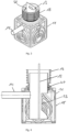
- the second shaft element 12 is in Fig. 1, 2
- the second shaft element 12 has a shaft base which is constructed like the first shaft element 11.
- the second shaft element 12 has a throttle element 16 which is arranged in the lower region of the second shaft element 12.
- the throttle element 16 is directly connected in a fluid-tight manner to the fluid outlet 18, specifically to the pipe forming the fluid outlet 18.
- the fluid inlet 17 of the second shaft element 12 is designed in the form of a wall opening. When installed, the wall opening is directly adjacent to the packed drainage ditch element 10, so that a direct fluid connection is formed between the second shaft element 12 and the packed drainage ditch element 10.
- the second shaft element 12 is flooded with purified rainwater through the wall opening.
- the throttle element 16 drains the rainwater through the fluid outlet 18 in a controlled manner.
- the fluid outlet 18 is located in the lower region of the shaft element 12 and extends horizontally in the form of a pipe starting from the throttle element 16 out of the second shaft element 12.
- the throttle element 16 is controlled, in particular remotely controlled, so that dynamic control of the drainage of rainwater is possible.
- the throttle element 16 is connected to a servomotor 21 by an actuator rod 22.
- the servomotor 21 is arranged above the second shaft element 12 in the shaft structure 19.
- the throttle element 16 can, for example, comprise a throttle valve or a slide valve or means for mechanical pipe deformation.
- the packed drainage unit shown is integrated into a packed drainage system that consists of a large number of packed drainage elements 10. If the packed drainage elements 10 are arranged in several levels, the packed drainage unit is installed in the lowest level. For this purpose, the packed drainage element 10 of the packed drainage unit is connected to other packed drainage elements of the overall system in a manner known per se, so that the packed drainage unit forms the inlet and outlet of the overall system.
- a packed trench unit that includes all of the above-mentioned components in one component.
- the cleaning unit and throttle unit are integrated into the packed trench or packed trench unit.
- the cleaning unit and throttle unit are each integrated into a shaft that fits the packed trench system. This ensures that the shafts and their functions fit the packed trench system and that the entire packed trench can be installed in an excavation pit.
- the cleaning and throttle units are located in the lower area (lowest level) of the packed trench.
- the cleaning unit in the shaft includes, for example, a slotted screen or sedimentation, adsorption and any type of mechanical pre-cleaning for filtering the incoming water.
- the slotted screen can be inserted into a pipe (guide cylinder) mounted in the shaft and is therefore easy to maintain, as it can simply be pulled out upwards if it becomes dirty.
- a corresponding slide extension can be formed between the slotted screen and the surface of the trench.
- the incoming water is led through the inlet pipe directly into the guide cylinder to the slotted screen and then runs cleaned through the slotted screen into the packed body trench.
- a gap is provided between the bottom of the shaft body and the slotted screen.
- the settling space in the guide cylinder in front of the slotted screen should be maintained at regular intervals depending on the load.
- the opening of the guide cylinder is sized so that the water can flow unhindered into the trench without unnecessary flow resistance.
- the slotted screen is arranged vertically and is guided in the guide cylinder via guide rails arranged on both sides.
- the guide cylinder can be supported on ribs of the shaft body and can, for example, be welded firmly to it.
- the throttle unit may have a throttle valve/flange valve inside it, which can be used to regulate the escaping water flow.
Landscapes
- Engineering & Computer Science (AREA)
- Health & Medical Sciences (AREA)
- Life Sciences & Earth Sciences (AREA)
- Hydrology & Water Resources (AREA)
- Public Health (AREA)
- Water Supply & Treatment (AREA)
- Environmental & Geological Engineering (AREA)
- Sewage (AREA)
- Sink And Installation For Waste Water (AREA)
Applications Claiming Priority (2)
| Application Number | Priority Date | Filing Date | Title |
|---|---|---|---|
| DE102018111300.5A DE102018111300A1 (de) | 2018-05-11 | 2018-05-11 | Füllkörperrigoleneinheit, Füllkörperrigolensystem und Schachtelement |
| PCT/EP2019/061831 WO2019215238A1 (de) | 2018-05-11 | 2019-05-08 | Füllkörperrigoleneinheit, füllkörperrigolensystem und schachtelement |
Publications (3)
| Publication Number | Publication Date |
|---|---|
| EP3791027A1 EP3791027A1 (de) | 2021-03-17 |
| EP3791027C0 EP3791027C0 (de) | 2024-08-07 |
| EP3791027B1 true EP3791027B1 (de) | 2024-08-07 |
Family
ID=66530025
Family Applications (1)
| Application Number | Title | Priority Date | Filing Date |
|---|---|---|---|
| EP19723753.0A Active EP3791027B1 (de) | 2018-05-11 | 2019-05-08 | Füllkörperrigoleneinheit, füllkörperrigolensystem und schachtelement |
Country Status (7)
| Country | Link |
|---|---|
| US (1) | US12006676B2 (pl) |
| EP (1) | EP3791027B1 (pl) |
| CN (1) | CN112105787A (pl) |
| DE (1) | DE102018111300A1 (pl) |
| PL (1) | PL3791027T3 (pl) |
| RU (1) | RU2768026C1 (pl) |
| WO (1) | WO2019215238A1 (pl) |
Families Citing this family (5)
| Publication number | Priority date | Publication date | Assignee | Title |
|---|---|---|---|---|
| DE102019108120A1 (de) * | 2019-03-28 | 2020-10-01 | ENREGIS GmbH | Speicher-/Versickerungssystem und Verfahren zur Zwischenspeicherung eines Fluids in einem Speicher-/Versickerungssystem |
| US11980835B2 (en) * | 2020-07-27 | 2024-05-14 | Foley Products Company, Llc | Double-filter basket for stormwater retention system drain |
| US20230243142A1 (en) * | 2021-10-07 | 2023-08-03 | Advanced Drainage Systems, Inc. | Stormwater management crate assembly with tapered columns and side panels with column bearing components |
| MX2024004140A (es) * | 2021-10-07 | 2024-05-10 | Advanced Drainage Syst | Conjunto de cajas para el manejo de aguas pluviales con columnas conicas. |
| TWI866776B (zh) * | 2024-02-06 | 2024-12-11 | 大鋒塑膠股份有限公司 | 管列式地下儲水槽及其製造方法 |
Citations (2)
| Publication number | Priority date | Publication date | Assignee | Title |
|---|---|---|---|---|
| EP0877126A2 (de) * | 1997-05-09 | 1998-11-11 | REHAU AG + Co | Versickerungsvorrichtung |
| CN202000464U (zh) * | 2011-03-10 | 2011-10-05 | 北京泰宁科创雨水利用技术股份有限公司 | 一种自动净化雨水检查井 |
Family Cites Families (27)
| Publication number | Priority date | Publication date | Assignee | Title |
|---|---|---|---|---|
| DE3418813C2 (de) | 1984-05-19 | 1994-02-24 | Vollmar Oskar Gmbh | Rückhaltesystem für Abwasser |
| DE3535163C1 (de) * | 1985-10-02 | 1987-04-09 | Klaus-Ulrich Dipl-Ing Giehl | Drosselvorrichtung |
| AUPM294493A0 (en) * | 1993-12-14 | 1994-01-13 | Urriola, Humberto | Underground drainage system |
| US5848856A (en) * | 1997-02-07 | 1998-12-15 | Invisible Structures, Inc. | Subsurface fluid drainage and storage systems |
| JP3104969B2 (ja) * | 1998-10-26 | 2000-10-30 | 株式会社トーテツ | 広域集水型地下貯水槽 |
| DE20002627U1 (de) * | 2000-02-15 | 2000-05-04 | Fränkische Rohrwerke Gebr. Kirchner GmbH + Co., 97486 Königsberg | Sickereinrichtung mit Filtereinrichtung |
| DE10348024A1 (de) * | 2003-10-15 | 2005-05-19 | Fränkische Rohrwerke Gebr. Kirchner Gmbh & Co. Kg | Rigolenanordnung mit Rigole und Schacht |
| US7080480B2 (en) * | 2004-01-15 | 2006-07-25 | Urban Root L.L.C. | Integrated tree root and storm water system |
| US7374670B2 (en) * | 2005-06-03 | 2008-05-20 | Potts David A | High aspect ratio wastewater system |
| DE202005007638U1 (de) * | 2005-05-10 | 2005-08-04 | Rehau Ag + Co. | Wasserspeicherelement |
| US7833413B1 (en) * | 2007-01-17 | 2010-11-16 | John Rotondo | Underground filtration system |
| WO2008142879A1 (ja) * | 2007-05-17 | 2008-11-27 | Totetu Mfg. Co. Ltd. | 除塵管理枡 |
| DE102008007227A1 (de) | 2008-02-01 | 2009-08-06 | Fränkische Rohrwerke Gebr. Kirchner Gmbh & Co. Kg | Anlage zur Regenwasserbewirtschaftung |
| WO2009140295A1 (en) * | 2008-05-12 | 2009-11-19 | Cudo Stormwater Products, Inc. | Modular underground water management systems |
| JP4168087B1 (ja) | 2008-06-25 | 2008-10-22 | 收平 小田 | 流水分派装置及び流水分派方法 |
| US20100021236A1 (en) * | 2008-07-17 | 2010-01-28 | Kreikemeier John E | Water Retention/Detention Structure |
| WO2011041850A1 (en) * | 2009-10-11 | 2011-04-14 | Wiese Innovations Pty Ltd | Water diversion system |
| US8360100B2 (en) * | 2010-04-23 | 2013-01-29 | Retain-It, Llc | Integrated bulk fluids management system |
| US8894866B1 (en) * | 2010-10-18 | 2014-11-25 | Stormwater Filters Corp. | Storm water treatment system and method |
| DE202012005674U1 (de) * | 2012-05-31 | 2012-08-02 | Maincor Anger Gmbh | Wartungsfreundlicher Versickerungskasten zum einfachen Aufbau einer leicht handhabbaren Versickerungsanordnung in Fertigmodulbauweise mit vorschaltbarer Filtereinrichtung |
| KR101222885B1 (ko) * | 2012-07-06 | 2013-01-17 | (주)청운환경기술 | 초기 우수를 배제한 우수 포집장치 |
| US20140105684A1 (en) * | 2012-10-15 | 2014-04-17 | Kristar Enterprises, Inc. | Modular Stormwater Storage System |
| NL1040485C2 (nl) * | 2013-11-05 | 2015-05-07 | Asbipro Handel En Productie B V | Drainage-systeem en modulair drainage-element. |
| CN105672461A (zh) | 2016-03-07 | 2016-06-15 | 济创环保工程(苏州)有限公司 | 一种可浮动拦渣的电控限流式智慧截流井 |
| DE202016101800U1 (de) * | 2016-04-06 | 2017-07-07 | Rehau Ag + Co. | Rigolenanordnung |
| US9732508B1 (en) * | 2016-04-21 | 2017-08-15 | Bio Clean Environmental Services, Inc. | Hexagonal module and assembly for storage of water underground |
| US11661363B2 (en) * | 2021-05-24 | 2023-05-30 | Heart Water, L.L.C. | Rainwater processing system and processing steps for producing potable functional water |
-
2018
- 2018-05-11 DE DE102018111300.5A patent/DE102018111300A1/de active Pending
-
2019
- 2019-05-08 US US17/056,255 patent/US12006676B2/en active Active
- 2019-05-08 WO PCT/EP2019/061831 patent/WO2019215238A1/de not_active Ceased
- 2019-05-08 RU RU2020139961A patent/RU2768026C1/ru active
- 2019-05-08 EP EP19723753.0A patent/EP3791027B1/de active Active
- 2019-05-08 CN CN201980031772.2A patent/CN112105787A/zh active Pending
- 2019-05-08 PL PL19723753.0T patent/PL3791027T3/pl unknown
Patent Citations (2)
| Publication number | Priority date | Publication date | Assignee | Title |
|---|---|---|---|---|
| EP0877126A2 (de) * | 1997-05-09 | 1998-11-11 | REHAU AG + Co | Versickerungsvorrichtung |
| CN202000464U (zh) * | 2011-03-10 | 2011-10-05 | 北京泰宁科创雨水利用技术股份有限公司 | 一种自动净化雨水检查井 |
Also Published As
| Publication number | Publication date |
|---|---|
| WO2019215238A1 (de) | 2019-11-14 |
| US12006676B2 (en) | 2024-06-11 |
| US20230054894A1 (en) | 2023-02-23 |
| CN112105787A (zh) | 2020-12-18 |
| PL3791027T3 (pl) | 2024-12-16 |
| EP3791027A1 (de) | 2021-03-17 |
| EP3791027C0 (de) | 2024-08-07 |
| DE102018111300A1 (de) | 2019-11-14 |
| RU2768026C1 (ru) | 2022-03-23 |
Similar Documents
| Publication | Publication Date | Title |
|---|---|---|
| EP3791027B1 (de) | Füllkörperrigoleneinheit, füllkörperrigolensystem und schachtelement | |
| EP3309310B1 (de) | Regenüberlaufbecken zum sammeln und speichern von wasser | |
| DE10123754A1 (de) | Rigolenanordnung sowie Rigolenbauteil zu dessen Aufbau | |
| EP2581508B1 (de) | Abwasserhebeanlage | |
| DE202009010367U1 (de) | Vorrichtung zur Trennung von Regenwasser von chemisch, biologisch und/oder toxisch belasteten Abwässern | |
| EP2508686B1 (de) | Rückhalteanlage für Niederschlagwasser und Abwasser | |
| EP3183048B1 (de) | Regenwasserfilter | |
| EP2871296B1 (de) | Filtersubstratrinnenelement und Filtersubstratrinnensystem | |
| DE2544051A1 (de) | Reinigungsvorrichtung | |
| EP3460133B1 (de) | Versickerungssystem | |
| EP2157249B1 (de) | Ablaufarmatur mit Geruchverschluss | |
| DE102010040645A1 (de) | Abwasserbehandlungsvorrichtung und Abwasserbehandlungsanlage mit einer derartigen Abwasserbehandlungsvorrichtung | |
| EP3199715B1 (de) | Überlauf für ein becken, insbesondere spülenbecken | |
| EP1690989B1 (de) | Versickerungsvorrichtung | |
| EP2636812A1 (de) | Verfahren und Vorrichtung zur Dachentwässerung in Form einer Hauptentwässerung und einer Notentwässerung | |
| EP2995731B1 (de) | Wasserablauf mit Mehrfachsiphon-Geruchsverschluss | |
| DE102013107153B4 (de) | Reinigungsschacht sowie Verfahren zur dezentralen Regenwasserbehandlung | |
| DE202017106033U1 (de) | Regenüberlaufbecken zum Sammeln und Speichern von Wasser | |
| EP1528168B1 (de) | Rigole zum Zwischenspeichern von Flüssigkeit, insbesondere Regenwasser | |
| DE102010030979A1 (de) | Rückhaltevorrichtung für eine Abwasserbehandlungsanordnung, Konstruktionseinheit gebildet aus Rückhaltevorrichtung und Abwasserbehandlungsanordnung | |
| DE202014011094U1 (de) | Filtersubstratrinnenelement | |
| EP2405063B1 (de) | Abwasserbehandlungsanordnung | |
| DE2822299A1 (de) | Regler fuer ein stroemungsmedium | |
| EP2823109B1 (de) | Abwasserbehandlungsanordnung | |
| EP0709529B1 (de) | Abwasserfiltersystem und daraus resultierendes Verfahren zur Reduzierung siebbarer Schmutzfrachtanteile an Entlastungsanlagen von Mischsystemen und Mischwasserklärbecken |
Legal Events
| Date | Code | Title | Description |
|---|---|---|---|
| STAA | Information on the status of an ep patent application or granted ep patent |
Free format text: STATUS: UNKNOWN |
|
| STAA | Information on the status of an ep patent application or granted ep patent |
Free format text: STATUS: THE INTERNATIONAL PUBLICATION HAS BEEN MADE |
|
| PUAI | Public reference made under article 153(3) epc to a published international application that has entered the european phase |
Free format text: ORIGINAL CODE: 0009012 |
|
| STAA | Information on the status of an ep patent application or granted ep patent |
Free format text: STATUS: REQUEST FOR EXAMINATION WAS MADE |
|
| 17P | Request for examination filed |
Effective date: 20201210 |
|
| AK | Designated contracting states |
Kind code of ref document: A1 Designated state(s): AL AT BE BG CH CY CZ DE DK EE ES FI FR GB GR HR HU IE IS IT LI LT LU LV MC MK MT NL NO PL PT RO RS SE SI SK SM TR |
|
| AX | Request for extension of the european patent |
Extension state: BA ME |
|
| DAV | Request for validation of the european patent (deleted) | ||
| DAX | Request for extension of the european patent (deleted) | ||
| RAP3 | Party data changed (applicant data changed or rights of an application transferred) |
Owner name: ACO AHLMANN SE & CO. KG |
|
| STAA | Information on the status of an ep patent application or granted ep patent |
Free format text: STATUS: EXAMINATION IS IN PROGRESS |
|
| 17Q | First examination report despatched |
Effective date: 20221205 |
|
| GRAP | Despatch of communication of intention to grant a patent |
Free format text: ORIGINAL CODE: EPIDOSNIGR1 |
|
| STAA | Information on the status of an ep patent application or granted ep patent |
Free format text: STATUS: GRANT OF PATENT IS INTENDED |
|
| INTG | Intention to grant announced |
Effective date: 20240315 |
|
| GRAS | Grant fee paid |
Free format text: ORIGINAL CODE: EPIDOSNIGR3 |
|
| GRAA | (expected) grant |
Free format text: ORIGINAL CODE: 0009210 |
|
| STAA | Information on the status of an ep patent application or granted ep patent |
Free format text: STATUS: THE PATENT HAS BEEN GRANTED |
|
| AK | Designated contracting states |
Kind code of ref document: B1 Designated state(s): AL AT BE BG CH CY CZ DE DK EE ES FI FR GB GR HR HU IE IS IT LI LT LU LV MC MK MT NL NO PL PT RO RS SE SI SK SM TR |
|
| REG | Reference to a national code |
Ref country code: GB Ref legal event code: FG4D Free format text: NOT ENGLISH |
|
| REG | Reference to a national code |
Ref country code: CH Ref legal event code: EP |
|
| REG | Reference to a national code |
Ref country code: DE Ref legal event code: R096 Ref document number: 502019011833 Country of ref document: DE |
|
| REG | Reference to a national code |
Ref country code: IE Ref legal event code: FG4D Free format text: LANGUAGE OF EP DOCUMENT: GERMAN |
|
| U01 | Request for unitary effect filed |
Effective date: 20240829 |
|
| U07 | Unitary effect registered |
Designated state(s): AT BE BG DE DK EE FI FR IT LT LU LV MT NL PT RO SE SI Effective date: 20240911 |
|
| PG25 | Lapsed in a contracting state [announced via postgrant information from national office to epo] |
Ref country code: NO Free format text: LAPSE BECAUSE OF FAILURE TO SUBMIT A TRANSLATION OF THE DESCRIPTION OR TO PAY THE FEE WITHIN THE PRESCRIBED TIME-LIMIT Effective date: 20241107 |
|
| PG25 | Lapsed in a contracting state [announced via postgrant information from national office to epo] |
Ref country code: GR Free format text: LAPSE BECAUSE OF FAILURE TO SUBMIT A TRANSLATION OF THE DESCRIPTION OR TO PAY THE FEE WITHIN THE PRESCRIBED TIME-LIMIT Effective date: 20241108 |
|
| PG25 | Lapsed in a contracting state [announced via postgrant information from national office to epo] |
Ref country code: IS Free format text: LAPSE BECAUSE OF FAILURE TO SUBMIT A TRANSLATION OF THE DESCRIPTION OR TO PAY THE FEE WITHIN THE PRESCRIBED TIME-LIMIT Effective date: 20241207 |
|
| PG25 | Lapsed in a contracting state [announced via postgrant information from national office to epo] |
Ref country code: HR Free format text: LAPSE BECAUSE OF FAILURE TO SUBMIT A TRANSLATION OF THE DESCRIPTION OR TO PAY THE FEE WITHIN THE PRESCRIBED TIME-LIMIT Effective date: 20240807 |
|
| PG25 | Lapsed in a contracting state [announced via postgrant information from national office to epo] |
Ref country code: RS Free format text: LAPSE BECAUSE OF FAILURE TO SUBMIT A TRANSLATION OF THE DESCRIPTION OR TO PAY THE FEE WITHIN THE PRESCRIBED TIME-LIMIT Effective date: 20241107 Ref country code: ES Free format text: LAPSE BECAUSE OF FAILURE TO SUBMIT A TRANSLATION OF THE DESCRIPTION OR TO PAY THE FEE WITHIN THE PRESCRIBED TIME-LIMIT Effective date: 20240807 |
|
| PG25 | Lapsed in a contracting state [announced via postgrant information from national office to epo] |
Ref country code: RS Free format text: LAPSE BECAUSE OF FAILURE TO SUBMIT A TRANSLATION OF THE DESCRIPTION OR TO PAY THE FEE WITHIN THE PRESCRIBED TIME-LIMIT Effective date: 20241107 Ref country code: NO Free format text: LAPSE BECAUSE OF FAILURE TO SUBMIT A TRANSLATION OF THE DESCRIPTION OR TO PAY THE FEE WITHIN THE PRESCRIBED TIME-LIMIT Effective date: 20241107 Ref country code: IS Free format text: LAPSE BECAUSE OF FAILURE TO SUBMIT A TRANSLATION OF THE DESCRIPTION OR TO PAY THE FEE WITHIN THE PRESCRIBED TIME-LIMIT Effective date: 20241207 Ref country code: HR Free format text: LAPSE BECAUSE OF FAILURE TO SUBMIT A TRANSLATION OF THE DESCRIPTION OR TO PAY THE FEE WITHIN THE PRESCRIBED TIME-LIMIT Effective date: 20240807 Ref country code: GR Free format text: LAPSE BECAUSE OF FAILURE TO SUBMIT A TRANSLATION OF THE DESCRIPTION OR TO PAY THE FEE WITHIN THE PRESCRIBED TIME-LIMIT Effective date: 20241108 Ref country code: ES Free format text: LAPSE BECAUSE OF FAILURE TO SUBMIT A TRANSLATION OF THE DESCRIPTION OR TO PAY THE FEE WITHIN THE PRESCRIBED TIME-LIMIT Effective date: 20240807 |
|
| PG25 | Lapsed in a contracting state [announced via postgrant information from national office to epo] |
Ref country code: SM Free format text: LAPSE BECAUSE OF FAILURE TO SUBMIT A TRANSLATION OF THE DESCRIPTION OR TO PAY THE FEE WITHIN THE PRESCRIBED TIME-LIMIT Effective date: 20240807 |
|
| PG25 | Lapsed in a contracting state [announced via postgrant information from national office to epo] |
Ref country code: CZ Free format text: LAPSE BECAUSE OF FAILURE TO SUBMIT A TRANSLATION OF THE DESCRIPTION OR TO PAY THE FEE WITHIN THE PRESCRIBED TIME-LIMIT Effective date: 20240807 |
|
| PG25 | Lapsed in a contracting state [announced via postgrant information from national office to epo] |
Ref country code: SK Free format text: LAPSE BECAUSE OF FAILURE TO SUBMIT A TRANSLATION OF THE DESCRIPTION OR TO PAY THE FEE WITHIN THE PRESCRIBED TIME-LIMIT Effective date: 20240807 |
|
| PLBE | No opposition filed within time limit |
Free format text: ORIGINAL CODE: 0009261 |
|
| STAA | Information on the status of an ep patent application or granted ep patent |
Free format text: STATUS: NO OPPOSITION FILED WITHIN TIME LIMIT |
|
| U20 | Renewal fee for the european patent with unitary effect paid |
Year of fee payment: 7 Effective date: 20250516 |
|
| PGFP | Annual fee paid to national office [announced via postgrant information from national office to epo] |
Ref country code: PL Payment date: 20250429 Year of fee payment: 7 |
|
| PGFP | Annual fee paid to national office [announced via postgrant information from national office to epo] |
Ref country code: GB Payment date: 20250522 Year of fee payment: 7 |
|
| 26N | No opposition filed |
Effective date: 20250508 |
|
| REG | Reference to a national code |
Ref country code: CH Ref legal event code: H13 Free format text: ST27 STATUS EVENT CODE: U-0-0-H10-H13 (AS PROVIDED BY THE NATIONAL OFFICE) Effective date: 20251223 |
|
| PG25 | Lapsed in a contracting state [announced via postgrant information from national office to epo] |
Ref country code: CH Free format text: LAPSE BECAUSE OF NON-PAYMENT OF DUE FEES Effective date: 20250531 |
|
| PG25 | Lapsed in a contracting state [announced via postgrant information from national office to epo] |
Ref country code: MC Free format text: LAPSE BECAUSE OF FAILURE TO SUBMIT A TRANSLATION OF THE DESCRIPTION OR TO PAY THE FEE WITHIN THE PRESCRIBED TIME-LIMIT Effective date: 20240807 |