EP3790097B1 - Batteriemodul - Google Patents
Batteriemodul Download PDFInfo
- Publication number
- EP3790097B1 EP3790097B1 EP19756082.4A EP19756082A EP3790097B1 EP 3790097 B1 EP3790097 B1 EP 3790097B1 EP 19756082 A EP19756082 A EP 19756082A EP 3790097 B1 EP3790097 B1 EP 3790097B1
- Authority
- EP
- European Patent Office
- Prior art keywords
- battery
- battery core
- cushion
- cushion portion
- gap
- Prior art date
- Legal status (The legal status is an assumption and is not a legal conclusion. Google has not performed a legal analysis and makes no representation as to the accuracy of the status listed.)
- Active
Links
Images





Classifications
-
- H—ELECTRICITY
- H01—ELECTRIC ELEMENTS
- H01M—PROCESSES OR MEANS, e.g. BATTERIES, FOR THE DIRECT CONVERSION OF CHEMICAL ENERGY INTO ELECTRICAL ENERGY
- H01M50/00—Constructional details or processes of manufacture of the non-active parts of electrochemical cells other than fuel cells, e.g. hybrid cells
- H01M50/20—Mountings; Secondary casings or frames; Racks, modules or packs; Suspension devices; Shock absorbers; Transport or carrying devices; Holders
- H01M50/289—Mountings; Secondary casings or frames; Racks, modules or packs; Suspension devices; Shock absorbers; Transport or carrying devices; Holders characterised by spacing elements or positioning means within frames, racks or packs
- H01M50/291—Mountings; Secondary casings or frames; Racks, modules or packs; Suspension devices; Shock absorbers; Transport or carrying devices; Holders characterised by spacing elements or positioning means within frames, racks or packs characterised by their shape
-
- H—ELECTRICITY
- H01—ELECTRIC ELEMENTS
- H01M—PROCESSES OR MEANS, e.g. BATTERIES, FOR THE DIRECT CONVERSION OF CHEMICAL ENERGY INTO ELECTRICAL ENERGY
- H01M10/00—Secondary cells; Manufacture thereof
- H01M10/05—Accumulators with non-aqueous electrolyte
- H01M10/052—Li-accumulators
-
- H—ELECTRICITY
- H01—ELECTRIC ELEMENTS
- H01M—PROCESSES OR MEANS, e.g. BATTERIES, FOR THE DIRECT CONVERSION OF CHEMICAL ENERGY INTO ELECTRICAL ENERGY
- H01M10/00—Secondary cells; Manufacture thereof
- H01M10/05—Accumulators with non-aqueous electrolyte
- H01M10/058—Construction or manufacture
- H01M10/0585—Construction or manufacture of accumulators having only flat construction elements, i.e. flat positive electrodes, flat negative electrodes and flat separators
-
- H—ELECTRICITY
- H01—ELECTRIC ELEMENTS
- H01M—PROCESSES OR MEANS, e.g. BATTERIES, FOR THE DIRECT CONVERSION OF CHEMICAL ENERGY INTO ELECTRICAL ENERGY
- H01M4/00—Electrodes
- H01M4/02—Electrodes composed of, or comprising, active material
- H01M4/13—Electrodes for accumulators with non-aqueous electrolyte, e.g. for lithium-accumulators; Processes of manufacture thereof
-
- H—ELECTRICITY
- H01—ELECTRIC ELEMENTS
- H01M—PROCESSES OR MEANS, e.g. BATTERIES, FOR THE DIRECT CONVERSION OF CHEMICAL ENERGY INTO ELECTRICAL ENERGY
- H01M50/00—Constructional details or processes of manufacture of the non-active parts of electrochemical cells other than fuel cells, e.g. hybrid cells
- H01M50/10—Primary casings; Jackets or wrappings
- H01M50/102—Primary casings; Jackets or wrappings characterised by their shape or physical structure
- H01M50/105—Pouches or flexible bags
-
- H—ELECTRICITY
- H01—ELECTRIC ELEMENTS
- H01M—PROCESSES OR MEANS, e.g. BATTERIES, FOR THE DIRECT CONVERSION OF CHEMICAL ENERGY INTO ELECTRICAL ENERGY
- H01M50/00—Constructional details or processes of manufacture of the non-active parts of electrochemical cells other than fuel cells, e.g. hybrid cells
- H01M50/10—Primary casings; Jackets or wrappings
- H01M50/102—Primary casings; Jackets or wrappings characterised by their shape or physical structure
- H01M50/107—Primary casings; Jackets or wrappings characterised by their shape or physical structure having curved cross-section, e.g. round or elliptic
-
- H—ELECTRICITY
- H01—ELECTRIC ELEMENTS
- H01M—PROCESSES OR MEANS, e.g. BATTERIES, FOR THE DIRECT CONVERSION OF CHEMICAL ENERGY INTO ELECTRICAL ENERGY
- H01M50/00—Constructional details or processes of manufacture of the non-active parts of electrochemical cells other than fuel cells, e.g. hybrid cells
- H01M50/10—Primary casings; Jackets or wrappings
- H01M50/116—Primary casings; Jackets or wrappings characterised by the material
- H01M50/124—Primary casings; Jackets or wrappings characterised by the material having a layered structure
-
- H—ELECTRICITY
- H01—ELECTRIC ELEMENTS
- H01M—PROCESSES OR MEANS, e.g. BATTERIES, FOR THE DIRECT CONVERSION OF CHEMICAL ENERGY INTO ELECTRICAL ENERGY
- H01M50/00—Constructional details or processes of manufacture of the non-active parts of electrochemical cells other than fuel cells, e.g. hybrid cells
- H01M50/10—Primary casings; Jackets or wrappings
- H01M50/131—Primary casings; Jackets or wrappings characterised by physical properties, e.g. gas permeability, size or heat resistance
- H01M50/136—Flexibility or foldability
-
- H—ELECTRICITY
- H01—ELECTRIC ELEMENTS
- H01M—PROCESSES OR MEANS, e.g. BATTERIES, FOR THE DIRECT CONVERSION OF CHEMICAL ENERGY INTO ELECTRICAL ENERGY
- H01M50/00—Constructional details or processes of manufacture of the non-active parts of electrochemical cells other than fuel cells, e.g. hybrid cells
- H01M50/20—Mountings; Secondary casings or frames; Racks, modules or packs; Suspension devices; Shock absorbers; Transport or carrying devices; Holders
- H01M50/204—Racks, modules or packs for multiple batteries or multiple cells
- H01M50/207—Racks, modules or packs for multiple batteries or multiple cells characterised by their shape
- H01M50/211—Racks, modules or packs for multiple batteries or multiple cells characterised by their shape adapted for pouch cells
-
- H—ELECTRICITY
- H01—ELECTRIC ELEMENTS
- H01M—PROCESSES OR MEANS, e.g. BATTERIES, FOR THE DIRECT CONVERSION OF CHEMICAL ENERGY INTO ELECTRICAL ENERGY
- H01M50/00—Constructional details or processes of manufacture of the non-active parts of electrochemical cells other than fuel cells, e.g. hybrid cells
- H01M50/20—Mountings; Secondary casings or frames; Racks, modules or packs; Suspension devices; Shock absorbers; Transport or carrying devices; Holders
- H01M50/204—Racks, modules or packs for multiple batteries or multiple cells
- H01M50/207—Racks, modules or packs for multiple batteries or multiple cells characterised by their shape
- H01M50/213—Racks, modules or packs for multiple batteries or multiple cells characterised by their shape adapted for cells having curved cross-section, e.g. round or elliptic
-
- H—ELECTRICITY
- H01—ELECTRIC ELEMENTS
- H01M—PROCESSES OR MEANS, e.g. BATTERIES, FOR THE DIRECT CONVERSION OF CHEMICAL ENERGY INTO ELECTRICAL ENERGY
- H01M50/00—Constructional details or processes of manufacture of the non-active parts of electrochemical cells other than fuel cells, e.g. hybrid cells
- H01M50/20—Mountings; Secondary casings or frames; Racks, modules or packs; Suspension devices; Shock absorbers; Transport or carrying devices; Holders
- H01M50/289—Mountings; Secondary casings or frames; Racks, modules or packs; Suspension devices; Shock absorbers; Transport or carrying devices; Holders characterised by spacing elements or positioning means within frames, racks or packs
- H01M50/293—Mountings; Secondary casings or frames; Racks, modules or packs; Suspension devices; Shock absorbers; Transport or carrying devices; Holders characterised by spacing elements or positioning means within frames, racks or packs characterised by the material
-
- Y—GENERAL TAGGING OF NEW TECHNOLOGICAL DEVELOPMENTS; GENERAL TAGGING OF CROSS-SECTIONAL TECHNOLOGIES SPANNING OVER SEVERAL SECTIONS OF THE IPC; TECHNICAL SUBJECTS COVERED BY FORMER USPC CROSS-REFERENCE ART COLLECTIONS [XRACs] AND DIGESTS
- Y02—TECHNOLOGIES OR APPLICATIONS FOR MITIGATION OR ADAPTATION AGAINST CLIMATE CHANGE
- Y02E—REDUCTION OF GREENHOUSE GAS [GHG] EMISSIONS, RELATED TO ENERGY GENERATION, TRANSMISSION OR DISTRIBUTION
- Y02E60/00—Enabling technologies; Technologies with a potential or indirect contribution to GHG emissions mitigation
- Y02E60/10—Energy storage using batteries
-
- Y—GENERAL TAGGING OF NEW TECHNOLOGICAL DEVELOPMENTS; GENERAL TAGGING OF CROSS-SECTIONAL TECHNOLOGIES SPANNING OVER SEVERAL SECTIONS OF THE IPC; TECHNICAL SUBJECTS COVERED BY FORMER USPC CROSS-REFERENCE ART COLLECTIONS [XRACs] AND DIGESTS
- Y02—TECHNOLOGIES OR APPLICATIONS FOR MITIGATION OR ADAPTATION AGAINST CLIMATE CHANGE
- Y02P—CLIMATE CHANGE MITIGATION TECHNOLOGIES IN THE PRODUCTION OR PROCESSING OF GOODS
- Y02P70/00—Climate change mitigation technologies in the production process for final industrial or consumer products
- Y02P70/50—Manufacturing or production processes characterised by the final manufactured product
Definitions
- the disclosure relates to the technical field of battery, and in particular to a battery module.
- the battery module includes a housing and a plurality of battery units disposed within the housing.
- Each battery unit includes a battery core.
- the battery core includes an electrode assembly and a package that covers the electrode assembly.
- the battery core has two end portions opposite to each other.
- the electrode assembly has a first electrode plate and a second electrode plate that have opposite polarities.
- the electrode assembly may be formed by stacking the first electrode plate, the second electrode plate, and the diaphragm together or spirally winding them together around the winding axis.
- the thickness of each of the first electrode plate and the second electrode plate close to the edge is smaller than the thickness of the central region thereof. Therefore, the gap between the first electrode plate and the second electrode plate of the electrode assembly at the end portions of the battery core becomes larger, and is larger than the gap between the first electrode plate and the second electrode plate in the central region of the battery core. Therefore, the phenomenon of lithium deposition may easily occur at the end potions of the battery core, which affects the cycle performance of the battery core.
- the document US 20160056439 A1 discloses a battery assembly for an electrified vehicle, including a plurality of battery cells and a plurality of battery cell separators, wherein each of the battery cell separators is arranged to separate adjacent battery cells from one another.
- the document US 20130017425 A1 discloses a lithium ion secondary battery cell including: a battery cell container, a laminated-type electrode group, and an electrolyte injected in the battery cell container in which the laminated-type electrode group are housed, wherein the laminated-type electrode group includes a positive electrode, a negative electrode, and a separator sandwiched between the positive electrode and the negative electrode.
- the embodiment of the disclosure provides a battery module, which can effectively reduce the gap between the first electrode plate and the second electrode plate through the cushion pad, thereby reducing the possibility of occurrence of lithium deposition at the end portions of the battery core, and improving the overall cycle performance of the battery module.
- an embodiment of the disclosure provides a battery module, including: two or more battery units, wherein each battery unit includes a battery core including two end portions opposed in a length direction thereof, and the two or more battery units are arranged side by side in a thickness direction of the battery core, in two adjacent battery units, a first gap is formed between two battery cores that are close to each other, and the first gap extends from one of the two end portions along the length direction, and in a direction from the two end portions to a center of the battery core, a dimension of the first gap gradually decreases along the thickness direction; and a cushion pad.
- the first gap penetrates through in the length direction, the cushion pad includes a first cushion portion and a second cushion portion; and in the thickness direction, the first cushion portion is arranged at one of the two end portions of the battery core, and the second cushion portion is arranged at the other of the two end portions.
- a ratio of a dimension of the first cushion portion to a dimension of the battery core is 0.06 to 0.15, and/or a ratio of a dimension of the second cushion portion to the dimension of the battery core is 0.06 to 0.15; or in a width direction of the battery core, the cushion pad has same dimension as the battery core.
- the cushion pad further includes an intermediate portion which is disposed between the first cushion portion and the second cushion portion and in contact with the battery core.
- respective surfaces of the first cushion portion, the second cushion portion, and the intermediate portion facing the battery core are connected to each other and are in smooth transition; and/or a surface of the battery core where the first gap is formed is arched, and respective surfaces of the first cushion portion, the second cushion portion, and the intermediate portion facing the battery core fit the battery core.
- the first cushion portion, the second cushion portion, and the intermediate portion are integral.
- an end face of the first cushion portion is aligned with an end face of the battery core in the length direction, and/or, an end face of the second cushion portion is aligned with the end face of the battery core in the length direction.
- the battery core includes an electrode assembly and a package, the electrode assembly is disposed in the package, and the electrode assembly includes a first electrode plate and a second electrode plate that have opposite polarities, the thickness of the first electrode plate and the second electrode plate gradually increases in the direction from the two end portions to the center of the battery core.
- the battery module further includes a housing within which the two or more battery units are disposed, a second gap is formed between the battery core in the two or more battery units adjacent to the housing and the housing, in the direction from the two end portions to the center of the battery core, a dimension of the second gap in the thickness direction gradually decreases, and the cushion pad is disposed in the second gap and is in contact with the end portion(s) of the battery core.
- each of the two or more battery units includes two or more battery cores, and an isolation member is disposed between two adjacent battery cores and configured to restrain expansion deformation of the battery cores in cooperation with the cushion pad.
- the battery module according to the embodiment of the disclosure includes two or more battery units and the cushion pad disposed between two adjacent battery units.
- the cushion pad is disposed between the two battery units in the thickness direction.
- a first gap is formed between two battery cores that are close to each other.
- the cushion pad is disposed in the first gap and is in contact with the end portion(s) of the battery core.
- the cushion pad provides supporting stress for the end portions of the battery core, thereby effectively reducing the gap between the first electrode plate and the second electrode plate, reducing the possibility of occurrence of lithium deposition at the end portions of the battery core, and improving the overall cycle performance of the battery module.
- battery module 20 housing 30 battery unit 31 battery core 31a end portion 31b end face 32 first gap 33 second gap 34 electrode assembly 34a first electrode plate 34aa first current collector 34ab first active material layer 34b diaphragm 34c second electrode plate 34ca second current collector 34cb second active material layer 35 package 40 cushion pad 41 first cushion portion 42 second cushion portion 43 intermediate portion 50 rigid isolation component X length direction Y thickness direction Z width direction.
- the terms “mount”, “connect with”, and “connect to” are to be understood broadly, for example, they may be referred to as fixed connection or detachable connection or integral connection; or, they may be referred to as direct connection or indirect connection through an intermediate medium.
- the specific meaning of the above terms in the disclosure may be understood by the skilled in the art based on the specific situation.
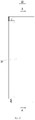
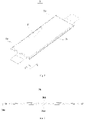
- the battery module 10 includes a housing 20, two or more battery units 30 and a cushion pad 40 disposed within the housing 20.
- the housing 20 has an accommodation space for accommodating the battery units 30.
- the housing 20 can protect the battery units 30.
- the battery unit 30 includes a battery core 31 and a fixing frame (not shown).
- the battery core 31 is connected to a fixed frame.
- the fixing frame is advantageous for improving the overall structural strength of the battery module 10.
- the battery core 31 has a substantially flat structure as a whole, and has a predetermined thickness, a predetermined length, and a predetermined width.
- the battery core 31 includes two end portions 31a that are opposed in the length direction X thereof. Each of the end portions 31a has an end face 31b.
- the end portion 31a of the battery core 31 is thinner and flatter than the central region of the battery core 31.
- the battery core 31 includes an electrode assembly 34 and a package 35.
- the package 35 has a receiving space, within which the main body of the electrode assembly 34 is received.
- the package 35 may be a soft casing. Alternatively, the package 35 may be manufactured by processing aluminum plastic film and steel plastic film.
- the main body thereof may be formed by stacking the first electrode plate, the second electrode plate, and the diaphragm together or by spirally winding the first electrode plate, the second electrode plate, and the diaphragm together around the winding axis, wherein the diaphragm is an insulator interposed between the first electrode plate and the second electrode plate.
- the first electrode plate is exemplified as a positive electrode plate, while the second electrode plate is a negative electrode plate.
- the first electrode plate may also be a negative electrode plate
- the second electrode plate may also be a positive electrode plate.
- the active material of the positive electrode plate is coated onto the coated region of the positive electrode plate
- the active material of the negative electrode plate is coated onto the coated region of the negative electrode plate.
- the uncoated region extending from the coated region of the main body functions as a tab.
- the electrode assembly includes two tabs, i.e., a positive tab and a negative tab, wherein the positive tab extends from the coated region of the positive electrode plate, and the negative tab extends from the coated region of the negative electrode plate.
- the first electrode plate 34a includes a first current collector 34aa and first active material layers 34ab.
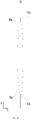
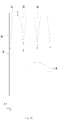
- the second electrode plate 34c includes a second current collector 34ca and second active material layers 34cb. Since the first electrode plate 34a and the second electrode plate 34c require to be subjected to cold pressing treatment during processing, the thickness of the cold-pressed first electrode plate 34a and the second electrode plate 34c as a whole gradually increases in a direction from the end portions 31a of the battery core 31 to the center of the battery core 31, so that the electrode assembly 34 according to the present embodiment, which is formed by stacking or winding the first electrode plate 34a, the second electrode plate 34c, and the diaphragm 34b together, has a structure in which the thickness of both ends thereof is smaller than the thickness of the center thereof, and in turn, so that the battery core 31 as a whole also has a structure in which the thickness of both ends thereof is smaller than the thickness of the center thereof (see Fig.
- the gap of each of the first electrode plate 34a and the second electrode plate 34c at the end portion 31a of the battery core 31 becomes large, and is larger than the gap of each of the first electrode plate 34a and the second electrode plate 34c in the central region of the battery core 31.
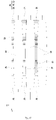
- the two or more battery units 30 are arranged side by side in the thickness direction Y of the battery core 31.
- the battery core 31 of one battery unit 30 and the battery core 31 of the other battery unit 30 are close to each other and disposed opposite to each other.
- a first gap 32 is formed between the two battery cores 31 that are close to each other.
- the first gap 32 extends from end portions 31a in the length direction X.
- the dimension of the first gap 32 in the thickness direction Y gradually decreases. That is to say, in the direction from the end portions 31a of the battery core 31 to the center of the battery core 31, the dimension of the first gap 32 in the thickness direction Y is narrowed.
- the cushion pad 40 is disposed between two adjacent battery units 30.
- the cushion pad 40 is disposed in the first gap 32 and is in contact with the end portion 31a of the battery core 31.
- the end portion 31a of the battery core 31 is at least partially covered by the cushion pad 40.
- the battery core 31 has two wide faces in the thickness direction Y.
- the battery core 31 has two narrow faces in the width direction Z.
- the wide faces of one battery core 31 of the two adjacent battery cores 31 is disposed corresponding to the wide faces of the other battery core 31 of the two adjacent battery cores 31.
- the region where the first gap 32 is formed on the wide face of the battery core 31 is curved.
- the cushion pad 40 is elastic.
- the cushion pad 40 may adopt a buffering material such as silica gel or polyurethane.
- the battery module 10 includes two or more battery units 30 and cushion pad 40 disposed between two adjacent battery units 30.
- the cushion pad 40 is disposed between the two battery units 30.
- the first gap 32 is formed between the two battery cores 31 that are close to each other.
- the cushion pad 40 is disposed in the first gap 32 and is in contact with the end portion 31a of the battery core 31.
- the cushion pad 40 can provide a supporting stress for the end portion 31a of the battery core 31, so that the gap between the first electrode plate 34a and the second electrode plate 34c at the end portion 31a of the battery core 31 can be effectively reduced, the possibility of occurrence of a lithium deposition phenomenon at the end portion 31a of the battery core 31 can be lowered, and the overall cycle performance of the battery module 10 can be improved.
- the battery core 31 as a whole expands, and the expanded end portion 31a of the battery core 31 may apply a pressing force to the cushion pad 40.
- the cushion pad 40 may apply a reaction force to the battery core 31 to avoid a large degree of expansion of the end portion 31a of the battery core 31, thereby ensuring that the degree of expansion of the end portion 31a of the battery core 31 tends to coincide with the degree of expansion of the central region of the battery core 31.
- the thickness of the cushion pad 40 gradually decreases so as to fit the first gap 32.
- the battery module 10 includes two or more battery units 30.
- Each battery unit 30 includes two battery cores 31.
- the first gap 32 is formed between the two battery cores 31 that are close to each other in the two adjacent battery units 30.
- the first gap 32 penetrates through in the length direction X.
- the cushion pad 40 includes a first cushion portion 41 and a second cushion portion 42. In the thickness direction Y, one of the two end portions 31a of the battery core 31 is arranged mutually with the first cushion portion 41, and the other of the two end portions 31a is arranged mutually with the second cushion portion 42.
- the first cushion portion 41 and the second cushion portion 42 are disposed at the two end portions 31a of the battery core 31, respectively.
- the first cushion portion 41 and the second cushion portion 42 are spaced apart from each other.
- the first cushion portion 41 and the second cushion portion 42 respectively provide a supporting stress for the two end portions 31a of the battery core 31, so that the gap between the first electrode plate 34a and the second electrode plate 34c at the end portion 31a of the battery core 31 can be effectively reduced.
- the first cushion portion 41 and the second cushion portion 42 respectively apply a restraining stress and provide a buffering effect to the two end portions 31a of the battery core 31 to reduce the degree of expansion and deformation of the end portion 31a of the battery core 31, such that the degree of expansion of the end portion 31a of the battery core 31 tends to coincide with the degree of expansion of the central region of the battery core 31.
- the surface of each of the first cushion portion 41 and the second cushion portion 42 facing the battery core 31 is shaped to match the surface of the battery core 31.
- the first cushion portion 41 and the second cushion portion 42 are both solid structural bodies.
- the wide faces of the battery core 31 are arched.
- the surface of the first cushion portion 41 facing the battery core 31 and the surface of the second cushion portion 42 facing the battery core 31 are also arched, so as to be shaped to fit the wide surfaces of the battery core 31.
- the first cushion portion 41 has an end face facing outward and away from the second cushion portion 42
- the second cushion portion 42 has an end face facing outward and away from the first cushion portion 41.
- the end face of the first cushion portion 41 is aligned with the end face 31b of the battery core 31 in the length direction X, so that the end portion 31a disposed opposite to the first cushion portion 41 does not appeared to be suspended, and therefore, it is possible to reduce the possibility that the gap between the first electrode plate 34a and the second electrode plate 34c at the end portion 31a of the battery core 31 cannot be reduced due to the portion of the end portion 31a that is not covered by the first cushion portion 41, and it is also possible to reduce the possibility of excessive expansion of the portion of the end portion 31a that is not covered by the first cushion portion 41.
- the end face of the second cushion portion 42 is aligned with the end face 31b of the battery core 31, so that the end portion 31a disposed opposite to the second cushion portion 42 does not appeared to be suspended, and therefore, it is possible to reduce the possibility that the gap between the first electrode plate 34a and the second electrode plate 34c at the end portion 31a of the battery core 31 cannot be reduced due to the portion of the end portion 31a that is not covered by the second cushion portion 42, and it is also possible to reduce the possibility of excessive expansion of the portion of the end portion 31a that is not covered by the second cushion portion 42.
- the end face of one of the first cushion portion 41 and the second cushion portion 42 is aligned with the end face 31b of the battery core 31.
- the ratio of the length dimension of at least one of the first cushion portion 41 and the second cushion portion 42 to the length dimension of the battery core 31 is 0.06 to 0.15.
- the first cushion portion 41 and the second cushion portion 42 both have same width dimension with the battery core 31 in the width direction Z of the battery core 31. In this way, the first cushion portion 41 and the second cushion portion 42 can effectively cover the end portion 31a of the battery core 31, so as to provide good supporting and buffering effect to the end portion 31a of the battery core 31, thereby improving balance of the buffering stress subjected by different regions of the end portion 31a of battery core 31.
- the abscissa indicates the number of cycles of the battery core 31, and the ordinate indicates the capacity retention ratio of the battery core 31.
- the cushion pad 40 includes the first cushion portion 41 and the second cushion portion 42.
- the thickness of the first cushion portion 41 and the thickness of the second cushion portion 42 gradually decrease, and are respectively adapted to match the first gap 32, such that the first cushion portion 41 and the second cushion portion 42 fit the battery cores 31 in the thickness direction Y with no gap.
- the first cushion portion 41 and the second cushion portion 42 are both structures having non-equal thickness. In the case where the first cushion portion 41 and the second cushion portion 42 are disposed between the two battery cores 31 that are close to each other, the capacity retention ratio also tends to decrease as the number of cycles increases.
- the rate of decrease in the capacity retention ratio when the first cushion portion 41 and the second cushion portion 42 are disposed between the two battery cores 31 that are close to each other is smaller than the rate of decrease in the capacity retention ratio when the cushion pad having equal thickness is disposed between the two battery cores 31 that are close to each other.
- the overall cycle performance of the battery core 31 can be improved.
- the abscissa indicates the number of cycles of the battery core 31, and the ordinate indicates the expansion force of the battery core 31.
- the cushion pad 40 includes the first cushion portion 41 and the second cushion portion 42. In the direction from the end portions 31a of the battery core 31 to the center of the battery core 31, the thickness of the first cushion portion 41 and the thickness of the second cushion portion 42 gradually decrease, and are respectively adapted to match the first gap 32.
- the first cushion portion 41 and the second cushion portion 42 are both structures having non-equal thickness.
- the expansion force of each of the battery cores 31 also tends to increase as the number of cycles increases.
- the rate of increase in the expansion force of each of the battery cores 31 when the first cushion portion 41 and the second cushion portion 42 are disposed between the two battery cores 31 that are close to each other is smaller than the rate of increase in the expansion force of each of the battery cores 31 when the cushion pad having equal thickness is disposed between the two battery cores 31 that are close to each other.
- the cycle performance can be improved and is better than the cycle performance when the cushion pad having equal thickness is disposed between the two battery cores 31 that are close to each other.
- the cushion pad 40 further includes an intermediate portion 43.
- the intermediate portion 43 is disposed between the first cushion portion 41 and the second cushion portion 42 and is in contact with the battery core 31.
- the broken lines in Figs. 13 and 14 are only used to schematically distinguish the first cushion portion 41, the intermediate portion 43 and the second cushion portion 42, and are not intended to limit the structure of the first cushion portion 41, the intermediate portion 43 and the second cushion portion 42, or other components.
- the first cushion portion 41 and the second cushion portion 42 can play a supporting and buffering effect on the end portions 31a of the battery core 31, and the intermediate portion 43 can play a supporting and buffering effect on the intermediate region of the battery core 31 located between the two end portions 31a.
- the force applied onto each region of the entire battery core 31 is more uniform, ensuring that the gap between the first electrode plate 34a and the second electrode plate 34c at the end portions 31a of the battery core 31 tends to coincide with the gap between the first electrode plate 34a and the second electrode plate 34c in the central region of the battery core 31, and ensuring that the degree of expansion of the end portions 31a of the battery core 31 tends to coincide with the degree of expansion of the central region of the battery cores 31, thereby further improving the cycle performance of the battery core 31.
- the surface of the intermediate portion 43 facing the battery core 31 is shaped to match the surface of the battery core 31.
- the intermediate portion 43 is a solid structural body.
- first cushion portion 41, the second cushion portion 42, and the intermediate portion 43 facing the battery core 31 fit, preferably fully contact the surface of the battery core 31.
- the respective faces of the first cushion portion 41, the second cushion portion 42, and the intermediate portion 43 are connected with each other and are in smooth transition, thereby reducing the possibility of occurrence of damage in the structure of the battery core 31 due to the stress concentration region on the surface of the battery core 31 applied by the cushion portion.
- the first cushion portion 41, the second cushion portion 42, and the intermediate portion 43 may be of a split structure.
- the first cushion portion 41, the second cushion portion 42, and the intermediate portion 43 may be of an integral structure.
- a second gap 33 is formed between the battery core 31 in the battery unit 30 adjacent to the housing 20 and the housing 20.
- the dimension of the second gap 33 in the thickness direction Y gradually decreases, that is, in the direction from the end portions 31a of the battery core 31 to the center of the battery core 31, the dimension of the second gap 33 in the thickness direction Y is narrowed.
- the cushion pad 40 is provided in the second gap 33. The cushion pad 40 is in contact with the end portion 31a of the battery core 31.
- the second gap 33 penetrates through in the length direction X.
- the cushion pad 40 includes the first cushion portion 41 and the second cushion portion 42.
- the first cushion portion 41 is disposed between one of the two end portions 31a of the battery core 31 and the housing 20, and the second cushion portion 42 is disposed between the other of the two end portions 31a of the battery core 31 and the housing 20.
- Both the first cushion portion 41 and the second cushion portion 42 can support the end portions 31a of the battery core 31, and also serve to buffer the expansion deformation of the end portions 31a of the battery core 31, thereby ensuring that the force applied onto each region of the entire battery core 31 adjacent to the housing 20 is more uniform, further improving the cycle performance of the battery core 31. Further, alternatively, referring to Fig.
- the cushion pad 40 includes the first cushion portion 41, the intermediate portion 43, and the second cushion portion 42.
- the intermediate portion 43 is disposed between the first cushion portion 41 and the second cushion portion 42, and therefore, it is possible to ensure that the gap between the first electrode plate 34a and the second electrode plate 34c at the end portion 31a of the battery core 31 tends to coincide with the gap between the first electrode plate 34a and the second electrode plate 34c in the central region of the battery core 31, and it is also possible to ensure that the degree of expansion of the end portion 31a of the battery core 31 tends to coincide with the degree of expansion of the central region of the battery cores 31, thereby further improving the cycle performance of the battery core 31.
- the battery unit 30 includes two or more battery cores 31.
- the two or more battery cores 31 are disposed within one fixed frame.
- a rigid isolation member 50 is disposed between the two adjacent battery cores 31.
- the rigid isolation member 50 may be an aluminum plate. When the battery cores 31 in the battery unit 30 expand, the two adjacent battery cores 31 may be constrained by the rigid isolation member 50.
- the rigid isolation member 50 can form a constraint on the battery core 31 in cooperation with the cushion pad 40 to effectively reduce the expansion deformation of the battery core 31, such that the degree of expansion of the end portion 31a of the battery core 31 tends to coincide with the degree of expansion of the central region of the battery core 31; on the other hand, the rigid isolation member 50 can reduce the possibility of structural damage in the first electrode plate 34a and the second electrode plate 34c caused by the mutual extruding resulting from expansion deformation of the two adjacent battery cores 31.
- the rigid isolation member 50 may be made of a material having thermal conductivity, so that the heat dissipation of the battery core 31 through the rigid isolation member 50 can be facilitated.
- the number of first gap 32 is two.
- the two first gaps 32 are formed between the two end portions 31a of the two adjacent battery cores 31, and the central regions of the two adjacent battery cores 31 are in contact with each other such that the two first gaps 32 are not continuous in the length direction X.
- One cushion pad 40 is disposed in each of the first gaps 32.
- each battery unit 30 includes one battery core 31. Within one fixed frame, one battery core 31 is disposed. The first gap 32 is formed between the two adjacent battery cores 31.
- the cushion pad 40 is provided between the two adjacent battery cores 31.
- the cushion pad 40 includes a first cushion portion 41 and a second cushion portion 42. The first cushion portion 41 and the second cushion portion 42 are spaced apart in the length direction X.
- the cushion pad 40 further includes an intermediate portion 43. The first cushion portion 41, the intermediate portion 43, and the second cushion portion 42 are sequentially arranged in the length direction X and are connected to each other.
- the first cushion portion 41, the intermediate portion 43, and the second cushion portion 42 may be of a split structure or an integral structure.
- the broken lines shown in Fig. 17 are only used to schematically distinguish the first cushion portion 41, the intermediate portion 43, and the second cushion portion 42, and are not intended to limit the structure of the first cushion portion 41, the intermediate portion 43, and the second cushion portion 42 or other components.
- the two tabs are led out from one end face 31b of the battery core 31.
- the first gap 32 is formed between one end portions 31a of each of the two adjacent battery cores 31, and the other end portions 31a of each of the two adjacent battery cores 31 are in contact with each other.
- the number of the first gap 32 is one.
- the first gap 32 does not penetrate through in the length direction X.
- the cushion pad 40 is disposed in the first gap 32. The cushion pad 40 is in contact with the end portion 31a of the battery core 31.
Landscapes
- Chemical & Material Sciences (AREA)
- Chemical Kinetics & Catalysis (AREA)
- Electrochemistry (AREA)
- General Chemical & Material Sciences (AREA)
- Engineering & Computer Science (AREA)
- Manufacturing & Machinery (AREA)
- Materials Engineering (AREA)
- Battery Mounting, Suspending (AREA)
Claims (8)
- Batteriemodul (10), umfassendzwei oder mehr Batterieeinheiten (30), wobei jede Batterieeinheit (30) einen Batteriekern (31) umfasst, der zwei Endabschnitte (31a) umfasst, die in einer Längsrichtung (X) davon gegenüberliegend sind, und die zwei oder mehr Batterieeinheiten (30) Seite an Seite in einer Dickenrichtung (Y) des Batteriekerns (31) angeordnet sind, in zwei benachbarten Batterieeinheiten (30) ein erster Spalt (32) zwischen zwei nahe beieinander liegenden Batteriekemen (31) gebildet ist, und der erste Spalt (32) sich von einem der zwei Endabschnitte (31a) entlang der Längsrichtung (X) erstreckt, und in einer Richtung von den zwei Endabschnitten (31a) zu einer Mitte des B atteriekerns (31) eine Abmessung des ersten Spalts (32) allmählich entlang der Dickenrichtung (Y) abnimmt; undein Dämpfungspolster (40), wobei das Dämpfungspolster (40) zwischen den zwei benachbarten Batterieeinheiten (30) vorgesehen ist, und das Dämpfungspolster (40) in dem ersten Spalt (32) angeordnet ist und mit dem/den Endabschnitt(en) (31a) des Batteriekerns (31) in Kontakt steht, wobeider erste Spalt (32) in der Längsrichtung (X) durchdringt, das Dämpfungspolster (40) einen ersten Polsterabschnitt (41) und einen zweiten Polsterabschnitt (42) umfasst; und in der Dickenrichtung (Y) der erste Polsterabschnitt (41) an einem der zwei Endabschnitte (31a) des Batteriekerns (31) angeordnet ist, und der zweite Polsterabschnitt (42) an dem anderen der zwei Endabschnitte (31a) angeordnet ist;in der Längsrichtung (X) ein Verhältnis einer Abmessung des ersten Polsterabschnitts (41) zu einer Abmessung des Batteriekerns (31) 0,06 bis 0,15 beträgt, und/oder ein Verhältnis einer Abmessung des zweiten Polsterabschnitts (42) zur Abmessung des Batteriekerns (31) 0,06 bis 0,15 beträgt; oder in einer Breitenrichtung (Z) des Batteriekerns (31) das Dämpfungspolster (40) dieselbe Abmessung wie der Batteriekern (31) aufweist.
- Batteriemodul (10) nach Anspruch 1, wobei das Polsterpolster (40) ferner einen Zwischenabschnitt (43) umfasst, der zwischen dem ersten Polsterabschnitt (41) und dem zweiten Polsterabschnitt (42) angeordnet ist und mit dem Batteriekern (31) in Kontakt steht.
- Batteriemodul (10) nach Anspruch 2, wobei jeweilige Oberflächen des ersten Polsterabschnitts (41), des zweiten Polsterabschnitts (42) und des Zwischenabschnitts (43), die dem Batteriekern (31) zugewandt sind, miteinander verbunden sind und in einem glatten Übergang sind; und/oder eine Oberfläche des Batteriekerns (31), wo der erste Spalt (32) gebildet ist, gewölbt ist, und jeweilige Oberflächen des ersten Pufferabschnitts (41), des zweiten Pufferabschnitts (42) und des Zwischenabschnitts (43), die dem Batteriekern (31) zugewandt sind, zu dem Batteriekern (31) passen.
- Batteriemodul (10) nach Anspruch 2, wobei der erste Polsterabschnitt (41), der zweite Polsterabschnitt (42) und der Zwischenabschnitt (43) einstückig sind.
- Batteriemodul (10) nach Anspruch 1, wobei eine Endfläche des ersten Polsterabschnitts (41) mit einer Endfläche (31b) des Batteriekerns (31) in der Längsrichtung (X) ausgerichtet ist, und/oder, eine Endfläche des zweiten Polsterabschnitts (42) mit der Endfläche (31b) des Batteriekerns (31) in der Längsrichtung (X) ausgerichtet ist.
- Batteriemodul (10) nach Anspruch 1, wobei der Batteriekern (31) eine Elektrodenanordnung (34) und ein Gehäuse (35) umfasst, die Elektrodenanordnung (34) in dem Gehäuse (35) angeordnet ist, und die Elektrodenanordnung (34) eine erste Elektrodenplatte (34a) und eine zweite Elektrodenplatte (34c) umfasst, die entgegengesetzten Polaritäten aufweisen, die Dicke der ersten Elektrodenplatte (34a) und der zweiten Elektrodenplatte (34c) allmählich in der Richtung von den zwei Endabschnitten (31a) zu der Mitte des Batteriekerns (31) zunimmt.
- Batteriemodul (10) nach Anspruch 1, wobei das Batteriemodul (10) ferner ein Gehäuse (20) umfasst, in dem die zwei oder mehr Batterieeinheiten (30) angeordnet sind, ein zweiter Spalt (33) zwischen dem Batteriekern (31) in den zwei oder mehr Batterieeinheiten (30) angrenzend an das Gehäuse (20) und dem Gehäuse (20) gebildet ist, in der Richtung von den zwei Endabschnitten (31a) zu der Mitte des Batteriekerns (31) eine Abmessung des zweiten Spalts (33) in der Dickenrichtung (Y) allmählich abnimmt, und das Dämpfungspolster (40) in dem zweiten Spalt angeordnet ist und mit dem/den Endabschnitt(en) (31a) des Batteriekerns (31) in Kontakt steht.
- Batteriemodul (10) nach einem der Ansprüche 1 bis 7, wobei jede der zwei oder mehr Batterieeinheiten (30) zwei oder mehr Batteriekerne (31) umfasst, und ein Isolationselement (50) zwischen zwei benachbarten Batteriekemen (31) angeordnet und konfiguriert ist, um eine Ausdehnungsverformung der Batteriekerne (31) im Zusammenwirken mit dem Dämpfungspolster (40) einzuschränken.
Applications Claiming Priority (2)
| Application Number | Priority Date | Filing Date | Title |
|---|---|---|---|
| CN201921040744.0U CN210006793U (zh) | 2019-07-04 | 2019-07-04 | 电池模组 |
| PCT/CN2019/095252 WO2021000336A1 (zh) | 2019-07-04 | 2019-07-09 | 电池模组 |
Publications (3)
| Publication Number | Publication Date |
|---|---|
| EP3790097A1 EP3790097A1 (de) | 2021-03-10 |
| EP3790097A4 EP3790097A4 (de) | 2021-03-10 |
| EP3790097B1 true EP3790097B1 (de) | 2023-01-04 |
Family
ID=69310414
Family Applications (1)
| Application Number | Title | Priority Date | Filing Date |
|---|---|---|---|
| EP19756082.4A Active EP3790097B1 (de) | 2019-07-04 | 2019-07-09 | Batteriemodul |
Country Status (5)
| Country | Link |
|---|---|
| US (1) | US12300844B2 (de) |
| EP (1) | EP3790097B1 (de) |
| CN (1) | CN210006793U (de) |
| HU (1) | HUE061048T2 (de) |
| WO (1) | WO2021000336A1 (de) |
Families Citing this family (7)
| Publication number | Priority date | Publication date | Assignee | Title |
|---|---|---|---|---|
| CN111354899B (zh) * | 2020-05-25 | 2020-10-23 | 比亚迪股份有限公司 | 电池包、电池模组、车辆以及储能装置 |
| JP7298550B2 (ja) * | 2020-06-02 | 2023-06-27 | トヨタ自動車株式会社 | 蓄電装置 |
| CN115832540A (zh) * | 2021-10-14 | 2023-03-21 | 宁德时代新能源科技股份有限公司 | 电池单体、电池、用电设备、电池单体的制造装置和方法 |
| CN118801049A (zh) * | 2023-04-13 | 2024-10-18 | 宁德时代新能源科技股份有限公司 | 电池单体、电池及用电装置 |
| CN119921039B (zh) * | 2023-10-31 | 2025-12-16 | 比亚迪股份有限公司 | 电池组件、电池包及用电系统 |
| CN117313281B (zh) * | 2023-11-30 | 2024-03-19 | 瑞浦兰钧能源股份有限公司 | 一种电池模组缓冲垫确认方法 |
| CN119601790A (zh) * | 2025-02-10 | 2025-03-11 | 宁德时代新能源科技股份有限公司 | 电池单体、电池装置及用电设备 |
Family Cites Families (17)
| Publication number | Priority date | Publication date | Assignee | Title |
|---|---|---|---|---|
| JP2000223096A (ja) * | 1999-01-28 | 2000-08-11 | Sanyo Electric Co Ltd | 電源装置 |
| DE102011015152A1 (de) * | 2011-03-25 | 2012-09-27 | Li-Tec Battery Gmbh | Energiespeichervorrichtung, Energiespeicherzelle und Wärmeleitelement mit elastischem Mittel |
| US9793584B2 (en) * | 2011-06-10 | 2017-10-17 | Samsung Sdi Co., Ltd. | Battery module |
| JP5616296B2 (ja) * | 2011-07-11 | 2014-10-29 | 株式会社日立製作所 | 蓄電池 |
| KR101272524B1 (ko) * | 2011-09-20 | 2013-06-11 | 현대자동차주식회사 | 배터리 셀용 방열판 및 이를 갖는 배터리 모듈 |
| CN104795527B (zh) * | 2014-01-21 | 2018-07-17 | 微宏动力系统(湖州)有限公司 | 电池模块 |
| US9640788B2 (en) * | 2014-08-22 | 2017-05-02 | Ford Global Technologies, Llc | Battery cell separator having contoured profile |
| US20160093854A1 (en) * | 2014-09-26 | 2016-03-31 | Johnson Controls Technology Company | Prismatic battery cell energy density for a lithium ion battery module |
| JP6520156B2 (ja) * | 2015-01-30 | 2019-05-29 | 株式会社豊田自動織機 | 蓄電装置及び蓄電装置モジュール |
| KR102284339B1 (ko) * | 2015-09-09 | 2021-08-04 | 에스케이이노베이션 주식회사 | 배터리 모듈 |
| US20170237112A1 (en) * | 2016-01-21 | 2017-08-17 | 24M Technologies, Inc. | Porous spacers for electrochemical cells |
| PL3349268T3 (pl) * | 2016-03-03 | 2020-05-18 | Lg Chem, Ltd. | Zespół ogniw posiadający człon miękkiej podkładki |
| CN206541873U (zh) | 2017-03-21 | 2017-10-03 | 宁德时代新能源科技股份有限公司 | 电池模组 |
| US10446894B2 (en) * | 2017-07-19 | 2019-10-15 | Ford Global Technologies, Llc | Array plate assemblies for applying compressive spring forces against battery cell stacks |
| CN109411651A (zh) * | 2017-08-15 | 2019-03-01 | 江苏海涛新能源科技有限公司 | 锂离子电芯搁置隔离装置 |
| CN109428024B (zh) * | 2017-08-31 | 2022-02-01 | 宁德时代新能源科技股份有限公司 | 电池单元及电池模组 |
| KR102762534B1 (ko) * | 2019-03-04 | 2025-02-03 | 주식회사 엘지에너지솔루션 | 스웰링 흡수 및 열 차단 기능을 갖는 패드 복합체를 구비하는 배터리 모듈, 이를 포함하는 배터리 팩 및 자동차 |
-
2019
- 2019-07-04 CN CN201921040744.0U patent/CN210006793U/zh active Active
- 2019-07-09 US US16/488,700 patent/US12300844B2/en active Active
- 2019-07-09 WO PCT/CN2019/095252 patent/WO2021000336A1/zh not_active Ceased
- 2019-07-09 EP EP19756082.4A patent/EP3790097B1/de active Active
- 2019-07-09 HU HUE19756082A patent/HUE061048T2/hu unknown
Also Published As
| Publication number | Publication date |
|---|---|
| HUE061048T2 (hu) | 2023-05-28 |
| WO2021000336A1 (zh) | 2021-01-07 |
| CN210006793U (zh) | 2020-01-31 |
| EP3790097A1 (de) | 2021-03-10 |
| EP3790097A4 (de) | 2021-03-10 |
| US20210359370A1 (en) | 2021-11-18 |
| US12300844B2 (en) | 2025-05-13 |
Similar Documents
| Publication | Publication Date | Title |
|---|---|---|
| EP3790097B1 (de) | Batteriemodul | |
| CN111180622B (zh) | 电池组 | |
| EP3852185A1 (de) | Stromversorgungsvorrichtung | |
| EP3800689B1 (de) | Sekundärbatterie, batteriemodul und elektrofahrzeug | |
| JP2002319383A (ja) | 電池モジュール | |
| CN111656602B (zh) | 二次电池及包括该二次电池的设备 | |
| EP3883033B1 (de) | Sekundärbatterie und batteriemodul | |
| US20240055699A1 (en) | Thermally Robust Cell Assembly, and Cell Module Comprising Such a Cell Assembly | |
| KR20230124577A (ko) | 조전지 | |
| KR102767949B1 (ko) | 배터리 팩용 단열시트 및 이를 구비한 배터리 팩 | |
| JP7554743B2 (ja) | 電源装置とこの電源装置を備える電動車両及び蓄電装置 | |
| JP6031388B2 (ja) | 組電池 | |
| KR102213758B1 (ko) | 복합 방열재를 적용한 고온 고율용 리튬이차전지 | |
| EP4641798A1 (de) | Batteriemodul und fahrzeug | |
| CN116724453A (zh) | 电池模块、电池包、用电装置和制造电池模块的方法 | |
| KR20220122400A (ko) | 원통형 전극 조립체의 고정 장치 | |
| CN217589117U (zh) | 一种电池及电池装置 | |
| EP3675202B1 (de) | Sekundärbatterie und batteriemodul | |
| JP2020187870A (ja) | 電池セル及び組電池 | |
| KR102773633B1 (ko) | 전지 셀의 가스 포켓부를 지지하는 스페이서를 포함하는 충방전 장치 | |
| CN212209588U (zh) | 电池包的电池模组以及电池包 | |
| CN114784415A (zh) | 一种电池及电池装置 | |
| CN222394884U (zh) | 一种单体电池、电池模组 | |
| CN221928287U (zh) | 电芯单体、电池系统和用电设备 | |
| CN222581299U (zh) | 电池 |
Legal Events
| Date | Code | Title | Description |
|---|---|---|---|
| STAA | Information on the status of an ep patent application or granted ep patent |
Free format text: STATUS: UNKNOWN |
|
| STAA | Information on the status of an ep patent application or granted ep patent |
Free format text: STATUS: THE INTERNATIONAL PUBLICATION HAS BEEN MADE |
|
| PUAI | Public reference made under article 153(3) epc to a published international application that has entered the european phase |
Free format text: ORIGINAL CODE: 0009012 |
|
| STAA | Information on the status of an ep patent application or granted ep patent |
Free format text: STATUS: REQUEST FOR EXAMINATION WAS MADE |
|
| 17P | Request for examination filed |
Effective date: 20190829 |
|
| A4 | Supplementary search report drawn up and despatched |
Effective date: 20210203 |
|
| AK | Designated contracting states |
Kind code of ref document: A1 Designated state(s): AL AT BE BG CH CY CZ DE DK EE ES FI FR GB GR HR HU IE IS IT LI LT LU LV MC MK MT NL NO PL PT RO RS SE SI SK SM TR |
|
| AX | Request for extension of the european patent |
Extension state: BA ME |
|
| STAA | Information on the status of an ep patent application or granted ep patent |
Free format text: STATUS: EXAMINATION IS IN PROGRESS |
|
| 17Q | First examination report despatched |
Effective date: 20210901 |
|
| GRAP | Despatch of communication of intention to grant a patent |
Free format text: ORIGINAL CODE: EPIDOSNIGR1 |
|
| STAA | Information on the status of an ep patent application or granted ep patent |
Free format text: STATUS: GRANT OF PATENT IS INTENDED |
|
| GRAJ | Information related to disapproval of communication of intention to grant by the applicant or resumption of examination proceedings by the epo deleted |
Free format text: ORIGINAL CODE: EPIDOSDIGR1 |
|
| STAA | Information on the status of an ep patent application or granted ep patent |
Free format text: STATUS: EXAMINATION IS IN PROGRESS |
|
| DAV | Request for validation of the european patent (deleted) | ||
| DAX | Request for extension of the european patent (deleted) | ||
| INTG | Intention to grant announced |
Effective date: 20220808 |
|
| INTC | Intention to grant announced (deleted) | ||
| GRAP | Despatch of communication of intention to grant a patent |
Free format text: ORIGINAL CODE: EPIDOSNIGR1 |
|
| STAA | Information on the status of an ep patent application or granted ep patent |
Free format text: STATUS: GRANT OF PATENT IS INTENDED |
|
| GRAS | Grant fee paid |
Free format text: ORIGINAL CODE: EPIDOSNIGR3 |
|
| INTG | Intention to grant announced |
Effective date: 20221024 |
|
| GRAA | (expected) grant |
Free format text: ORIGINAL CODE: 0009210 |
|
| STAA | Information on the status of an ep patent application or granted ep patent |
Free format text: STATUS: THE PATENT HAS BEEN GRANTED |
|
| RIN1 | Information on inventor provided before grant (corrected) |
Inventor name: LIN, GUANGLIANG Inventor name: YANG, KAI Inventor name: WANG, YUWEN |
|
| RAP3 | Party data changed (applicant data changed or rights of an application transferred) |
Owner name: JIANGSU CONTEMPORARY AMPEREX TECHNOLOGY LIMITED |
|
| AK | Designated contracting states |
Kind code of ref document: B1 Designated state(s): AL AT BE BG CH CY CZ DE DK EE ES FI FR GB GR HR HU IE IS IT LI LT LU LV MC MK MT NL NO PL PT RO RS SE SI SK SM TR |
|
| REG | Reference to a national code |
Ref country code: GB Ref legal event code: FG4D |
|
| REG | Reference to a national code |
Ref country code: CH Ref legal event code: EP |
|
| REG | Reference to a national code |
Ref country code: AT Ref legal event code: REF Ref document number: 1542588 Country of ref document: AT Kind code of ref document: T Effective date: 20230115 |
|
| REG | Reference to a national code |
Ref country code: DE Ref legal event code: R096 Ref document number: 602019024002 Country of ref document: DE |
|
| REG | Reference to a national code |
Ref country code: IE Ref legal event code: FG4D |
|
| REG | Reference to a national code |
Ref country code: SE Ref legal event code: TRGR |
|
| REG | Reference to a national code |
Ref country code: LT Ref legal event code: MG9D |
|
| REG | Reference to a national code |
Ref country code: NL Ref legal event code: MP Effective date: 20230104 |
|
| REG | Reference to a national code |
Ref country code: HU Ref legal event code: AG4A Ref document number: E061048 Country of ref document: HU |
|
| P01 | Opt-out of the competence of the unified patent court (upc) registered |
Effective date: 20230522 |
|
| PG25 | Lapsed in a contracting state [announced via postgrant information from national office to epo] |
Ref country code: NL Free format text: LAPSE BECAUSE OF FAILURE TO SUBMIT A TRANSLATION OF THE DESCRIPTION OR TO PAY THE FEE WITHIN THE PRESCRIBED TIME-LIMIT Effective date: 20230104 |
|
| PG25 | Lapsed in a contracting state [announced via postgrant information from national office to epo] |
Ref country code: RS Free format text: LAPSE BECAUSE OF FAILURE TO SUBMIT A TRANSLATION OF THE DESCRIPTION OR TO PAY THE FEE WITHIN THE PRESCRIBED TIME-LIMIT Effective date: 20230104 Ref country code: PT Free format text: LAPSE BECAUSE OF FAILURE TO SUBMIT A TRANSLATION OF THE DESCRIPTION OR TO PAY THE FEE WITHIN THE PRESCRIBED TIME-LIMIT Effective date: 20230504 Ref country code: NO Free format text: LAPSE BECAUSE OF FAILURE TO SUBMIT A TRANSLATION OF THE DESCRIPTION OR TO PAY THE FEE WITHIN THE PRESCRIBED TIME-LIMIT Effective date: 20230404 Ref country code: LV Free format text: LAPSE BECAUSE OF FAILURE TO SUBMIT A TRANSLATION OF THE DESCRIPTION OR TO PAY THE FEE WITHIN THE PRESCRIBED TIME-LIMIT Effective date: 20230104 Ref country code: LT Free format text: LAPSE BECAUSE OF FAILURE TO SUBMIT A TRANSLATION OF THE DESCRIPTION OR TO PAY THE FEE WITHIN THE PRESCRIBED TIME-LIMIT Effective date: 20230104 Ref country code: HR Free format text: LAPSE BECAUSE OF FAILURE TO SUBMIT A TRANSLATION OF THE DESCRIPTION OR TO PAY THE FEE WITHIN THE PRESCRIBED TIME-LIMIT Effective date: 20230104 Ref country code: ES Free format text: LAPSE BECAUSE OF FAILURE TO SUBMIT A TRANSLATION OF THE DESCRIPTION OR TO PAY THE FEE WITHIN THE PRESCRIBED TIME-LIMIT Effective date: 20230104 |
|
| PG25 | Lapsed in a contracting state [announced via postgrant information from national office to epo] |
Ref country code: PL Free format text: LAPSE BECAUSE OF FAILURE TO SUBMIT A TRANSLATION OF THE DESCRIPTION OR TO PAY THE FEE WITHIN THE PRESCRIBED TIME-LIMIT Effective date: 20230104 Ref country code: IS Free format text: LAPSE BECAUSE OF FAILURE TO SUBMIT A TRANSLATION OF THE DESCRIPTION OR TO PAY THE FEE WITHIN THE PRESCRIBED TIME-LIMIT Effective date: 20230504 Ref country code: GR Free format text: LAPSE BECAUSE OF FAILURE TO SUBMIT A TRANSLATION OF THE DESCRIPTION OR TO PAY THE FEE WITHIN THE PRESCRIBED TIME-LIMIT Effective date: 20230405 Ref country code: FI Free format text: LAPSE BECAUSE OF FAILURE TO SUBMIT A TRANSLATION OF THE DESCRIPTION OR TO PAY THE FEE WITHIN THE PRESCRIBED TIME-LIMIT Effective date: 20230104 |
|
| REG | Reference to a national code |
Ref country code: DE Ref legal event code: R097 Ref document number: 602019024002 Country of ref document: DE |
|
| PG25 | Lapsed in a contracting state [announced via postgrant information from national office to epo] |
Ref country code: SM Free format text: LAPSE BECAUSE OF FAILURE TO SUBMIT A TRANSLATION OF THE DESCRIPTION OR TO PAY THE FEE WITHIN THE PRESCRIBED TIME-LIMIT Effective date: 20230104 Ref country code: RO Free format text: LAPSE BECAUSE OF FAILURE TO SUBMIT A TRANSLATION OF THE DESCRIPTION OR TO PAY THE FEE WITHIN THE PRESCRIBED TIME-LIMIT Effective date: 20230104 Ref country code: EE Free format text: LAPSE BECAUSE OF FAILURE TO SUBMIT A TRANSLATION OF THE DESCRIPTION OR TO PAY THE FEE WITHIN THE PRESCRIBED TIME-LIMIT Effective date: 20230104 Ref country code: DK Free format text: LAPSE BECAUSE OF FAILURE TO SUBMIT A TRANSLATION OF THE DESCRIPTION OR TO PAY THE FEE WITHIN THE PRESCRIBED TIME-LIMIT Effective date: 20230104 Ref country code: CZ Free format text: LAPSE BECAUSE OF FAILURE TO SUBMIT A TRANSLATION OF THE DESCRIPTION OR TO PAY THE FEE WITHIN THE PRESCRIBED TIME-LIMIT Effective date: 20230104 |
|
| PLBE | No opposition filed within time limit |
Free format text: ORIGINAL CODE: 0009261 |
|
| STAA | Information on the status of an ep patent application or granted ep patent |
Free format text: STATUS: NO OPPOSITION FILED WITHIN TIME LIMIT |
|
| PG25 | Lapsed in a contracting state [announced via postgrant information from national office to epo] |
Ref country code: SK Free format text: LAPSE BECAUSE OF FAILURE TO SUBMIT A TRANSLATION OF THE DESCRIPTION OR TO PAY THE FEE WITHIN THE PRESCRIBED TIME-LIMIT Effective date: 20230104 |
|
| 26N | No opposition filed |
Effective date: 20231005 |
|
| REG | Reference to a national code |
Ref country code: AT Ref legal event code: UEP Ref document number: 1542588 Country of ref document: AT Kind code of ref document: T Effective date: 20230104 |
|
| PG25 | Lapsed in a contracting state [announced via postgrant information from national office to epo] |
Ref country code: SI Free format text: LAPSE BECAUSE OF FAILURE TO SUBMIT A TRANSLATION OF THE DESCRIPTION OR TO PAY THE FEE WITHIN THE PRESCRIBED TIME-LIMIT Effective date: 20230104 |
|
| PG25 | Lapsed in a contracting state [announced via postgrant information from national office to epo] |
Ref country code: MC Free format text: LAPSE BECAUSE OF FAILURE TO SUBMIT A TRANSLATION OF THE DESCRIPTION OR TO PAY THE FEE WITHIN THE PRESCRIBED TIME-LIMIT Effective date: 20230104 |
|
| PG25 | Lapsed in a contracting state [announced via postgrant information from national office to epo] |
Ref country code: MC Free format text: LAPSE BECAUSE OF FAILURE TO SUBMIT A TRANSLATION OF THE DESCRIPTION OR TO PAY THE FEE WITHIN THE PRESCRIBED TIME-LIMIT Effective date: 20230104 |
|
| REG | Reference to a national code |
Ref country code: CH Ref legal event code: PL |
|
| PG25 | Lapsed in a contracting state [announced via postgrant information from national office to epo] |
Ref country code: LU Free format text: LAPSE BECAUSE OF NON-PAYMENT OF DUE FEES Effective date: 20230709 |
|
| PG25 | Lapsed in a contracting state [announced via postgrant information from national office to epo] |
Ref country code: LU Free format text: LAPSE BECAUSE OF NON-PAYMENT OF DUE FEES Effective date: 20230709 |
|
| REG | Reference to a national code |
Ref country code: IE Ref legal event code: MM4A |
|
| PG25 | Lapsed in a contracting state [announced via postgrant information from national office to epo] |
Ref country code: CH Free format text: LAPSE BECAUSE OF NON-PAYMENT OF DUE FEES Effective date: 20230731 |
|
| PG25 | Lapsed in a contracting state [announced via postgrant information from national office to epo] |
Ref country code: IE Free format text: LAPSE BECAUSE OF NON-PAYMENT OF DUE FEES Effective date: 20230709 |
|
| PG25 | Lapsed in a contracting state [announced via postgrant information from national office to epo] |
Ref country code: IE Free format text: LAPSE BECAUSE OF NON-PAYMENT OF DUE FEES Effective date: 20230709 |
|
| PG25 | Lapsed in a contracting state [announced via postgrant information from national office to epo] |
Ref country code: BG Free format text: LAPSE BECAUSE OF FAILURE TO SUBMIT A TRANSLATION OF THE DESCRIPTION OR TO PAY THE FEE WITHIN THE PRESCRIBED TIME-LIMIT Effective date: 20230104 |
|
| PG25 | Lapsed in a contracting state [announced via postgrant information from national office to epo] |
Ref country code: BG Free format text: LAPSE BECAUSE OF FAILURE TO SUBMIT A TRANSLATION OF THE DESCRIPTION OR TO PAY THE FEE WITHIN THE PRESCRIBED TIME-LIMIT Effective date: 20230104 |
|
| PGFP | Annual fee paid to national office [announced via postgrant information from national office to epo] |
Ref country code: GB Payment date: 20250522 Year of fee payment: 7 |
|
| PGFP | Annual fee paid to national office [announced via postgrant information from national office to epo] |
Ref country code: BE Payment date: 20250619 Year of fee payment: 7 |
|
| PGFP | Annual fee paid to national office [announced via postgrant information from national office to epo] |
Ref country code: FR Payment date: 20250523 Year of fee payment: 7 |
|
| PG25 | Lapsed in a contracting state [announced via postgrant information from national office to epo] |
Ref country code: CY Free format text: LAPSE BECAUSE OF FAILURE TO SUBMIT A TRANSLATION OF THE DESCRIPTION OR TO PAY THE FEE WITHIN THE PRESCRIBED TIME-LIMIT; INVALID AB INITIO Effective date: 20190709 |
|
| PGFP | Annual fee paid to national office [announced via postgrant information from national office to epo] |
Ref country code: SE Payment date: 20250528 Year of fee payment: 7 |
|
| PGFP | Annual fee paid to national office [announced via postgrant information from national office to epo] |
Ref country code: HU Payment date: 20250610 Year of fee payment: 7 |
|
| PGFP | Annual fee paid to national office [announced via postgrant information from national office to epo] |
Ref country code: DE Payment date: 20250521 Year of fee payment: 7 |
|
| PGFP | Annual fee paid to national office [announced via postgrant information from national office to epo] |
Ref country code: IT Payment date: 20250623 Year of fee payment: 7 |
|
| PGFP | Annual fee paid to national office [announced via postgrant information from national office to epo] |
Ref country code: AT Payment date: 20250625 Year of fee payment: 7 |
|
| PG25 | Lapsed in a contracting state [announced via postgrant information from national office to epo] |
Ref country code: TR Free format text: LAPSE BECAUSE OF FAILURE TO SUBMIT A TRANSLATION OF THE DESCRIPTION OR TO PAY THE FEE WITHIN THE PRESCRIBED TIME-LIMIT Effective date: 20230104 |