EP3788707B1 - Potentialausgleichsystem für einen modularen multilevel-stromrichter - Google Patents
Potentialausgleichsystem für einen modularen multilevel-stromrichter Download PDFInfo
- Publication number
- EP3788707B1 EP3788707B1 EP18734771.1A EP18734771A EP3788707B1 EP 3788707 B1 EP3788707 B1 EP 3788707B1 EP 18734771 A EP18734771 A EP 18734771A EP 3788707 B1 EP3788707 B1 EP 3788707B1
- Authority
- EP
- European Patent Office
- Prior art keywords
- power converter
- end position
- contact
- pole
- contacts
- Prior art date
- Legal status (The legal status is an assumption and is not a legal conclusion. Google has not performed a legal analysis and makes no representation as to the accuracy of the status listed.)
- Active
Links
Images



Classifications
-
- H—ELECTRICITY
- H02—GENERATION; CONVERSION OR DISTRIBUTION OF ELECTRIC POWER
- H02M—APPARATUS FOR CONVERSION BETWEEN AC AND AC, BETWEEN AC AND DC, OR BETWEEN DC AND DC, AND FOR USE WITH MAINS OR SIMILAR POWER SUPPLY SYSTEMS; CONVERSION OF DC OR AC INPUT POWER INTO SURGE OUTPUT POWER; CONTROL OR REGULATION THEREOF
- H02M1/00—Details of apparatus for conversion
- H02M1/44—Circuits or arrangements for compensating for electromagnetic interference in converters or inverters
-
- H—ELECTRICITY
- H02—GENERATION; CONVERSION OR DISTRIBUTION OF ELECTRIC POWER
- H02M—APPARATUS FOR CONVERSION BETWEEN AC AND AC, BETWEEN AC AND DC, OR BETWEEN DC AND DC, AND FOR USE WITH MAINS OR SIMILAR POWER SUPPLY SYSTEMS; CONVERSION OF DC OR AC INPUT POWER INTO SURGE OUTPUT POWER; CONTROL OR REGULATION THEREOF
- H02M7/00—Conversion of AC power input into DC power output; Conversion of DC power input into AC power output
- H02M7/42—Conversion of DC power input into AC power output without possibility of reversal
- H02M7/44—Conversion of DC power input into AC power output without possibility of reversal by static converters
- H02M7/48—Conversion of DC power input into AC power output without possibility of reversal by static converters using discharge tubes with control electrode or semiconductor devices with control electrode
- H02M7/483—Converters with outputs that each can have more than two voltages levels
-
- H—ELECTRICITY
- H02—GENERATION; CONVERSION OR DISTRIBUTION OF ELECTRIC POWER
- H02M—APPARATUS FOR CONVERSION BETWEEN AC AND AC, BETWEEN AC AND DC, OR BETWEEN DC AND DC, AND FOR USE WITH MAINS OR SIMILAR POWER SUPPLY SYSTEMS; CONVERSION OF DC OR AC INPUT POWER INTO SURGE OUTPUT POWER; CONTROL OR REGULATION THEREOF
- H02M7/00—Conversion of AC power input into DC power output; Conversion of DC power input into AC power output
- H02M7/42—Conversion of DC power input into AC power output without possibility of reversal
- H02M7/44—Conversion of DC power input into AC power output without possibility of reversal by static converters
- H02M7/48—Conversion of DC power input into AC power output without possibility of reversal by static converters using discharge tubes with control electrode or semiconductor devices with control electrode
- H02M7/483—Converters with outputs that each can have more than two voltages levels
- H02M7/4835—Converters with outputs that each can have more than two voltages levels comprising two or more cells, each including a switchable capacitor, the capacitors having a nominal charge voltage which corresponds to a given fraction of the input voltage, and the capacitors being selectively connected in series to determine the instantaneous output voltage
-
- H—ELECTRICITY
- H01—ELECTRIC ELEMENTS
- H01H—ELECTRIC SWITCHES; RELAYS; SELECTORS; EMERGENCY PROTECTIVE DEVICES
- H01H31/00—Air-break switches for high tension without arc-extinguishing or arc-preventing means
- H01H31/003—Earthing switches
Definitions
- the invention relates to a modular multilevel converter with a number of converter modules, each of which has a direct voltage source, for example a capacitor.
- each DC voltage source is discharged and at least one pole of each DC voltage source is at ground potential.
- the potential connection is achieved via a large number of sliding contacts connected in series or by manually inserted bridging cables.
- the large number of contacts connected in series can lead to an interruption of the earth potential if two contacts fail.
- a grounding device with a retractable bridging cable which has an insulating section and a grounding section. If necessary, the grounding section is pulled over the power converter modules.
- the invention is based on the object of specifying a potential equalization system for a modular multilevel converter with a plurality of converter modules, each of which has a DC voltage source, which improves the ability to connect the DC voltage sources to a ground potential.
- the object is achieved according to the invention by a potential equalization system having the features of claim 1 and a modular multilevel power converter having the features of claim 9 .
- a potential equalization system for a modular multilevel converter, which has a number of converter modules (3), each with a DC voltage source (13), comprises pole contacts, which are each electrically connected to a pole of a DC voltage source, and at least one electrically conductive contacting element, which is connected between a first End position in which it is electrically separated from the converter modules, and a second end position in which it contacts pole contacts of different DC voltage sources and can be placed at ground potential, can be moved, for example by a manual, mechanical or electrical drive.
- poles of DC voltage sources of different power converter modules of the power converter can therefore be connected to a ground potential, in that pole contacts connected to the poles are electrically connected to one another by a contacting element and the contacting element is connected to the ground potential.
- the DC voltage sources connected to the contacting element via the other pole contacts remain connected to ground potential. This advantageously increases the reliability of the connection of many DC voltage sources to the ground potential compared to a connection via a large number of contacts connected in series.
- At least one contacting element is an electrical shield for shielding a plurality of power converter modules, which is rotatable about an axis of rotation between the first end position and the second end position.
- the shielding has a shielding tube from which at least one shielding contact protrudes the second end position of the shield contacts at least one pole contact, and the axis of rotation of the shield is a longitudinal axis of the shield tube.
- at least one shielding contact is designed as a handle arranged on the shielding tube, which makes contact with a plurality of pole contacts in the second end position of the shielding.
- the shield is made of aluminum, for example.
- the aforementioned configurations of the invention use a shielding of power converter modules that is generally required in any case as a contacting element or provide the contacting element with a shielding function.
- the outlay on materials and construction is advantageously reduced in comparison with shielding and contacting elements that are implemented separately.
- a further embodiment of the invention provides that at least one contacting element is an electrically conductive contact cable, for example a copper cable, which can be guided on an electrically insulating guide cable routed via pole contacts of different DC voltage sources, in the first end position it does not touch any pole contact and in the second end position on the pole contacts over which the guide rope is guided.
- the guide cable is routed over a first cable drum
- the contact cable is routed over a second cable drum
- both cable drums are mounted on a drive shaft that can be driven manually, mechanically, or electrically.
- a contacting element designed as a contact cable enables an electrical connection of the pole contacts that can be flexibly adapted to the spatial distribution of the pole contacts, in particular also a connection of pole contacts that are spatially relatively far apart from one another.
- a modular multilevel converter according to the invention in particular a self-commutated modular multilevel converter, comprises a plurality of converter modules, each with a DC voltage source, which is designed, for example, as a capacitor or an electrical interconnection of a plurality of capacitors, and a potential equalization system according to the invention.
- a power converter result from the advantages of a potential equalization system according to the invention, which have already been mentioned above, and are therefore not listed again here.
- the converter has a plurality of module groups, each of which has a plurality of converter modules, each with at least one pole contact.
- the equipotential bonding system has a contacting element which, in its second end position, makes contact with all the pole contacts of the group of modules.
- a common drive can be provided with which all contacting elements can be driven simultaneously.
- the cost and material expenditure for moving the contacting elements can be reduced and, on the other hand, the movements of the contacting elements can be synchronized more easily.
- figure 1 shows a circuit diagram of a self-commutated modular multilevel power converter 1.
- the power converter 1 has a plurality of power converter modules 3 connected in series during normal operation of the power converter 1, only a few of which are shown.
- the power converter modules 3 form three module groups 5 to 7 arranged one above the other.
- the power converter 1 also has a potential equalization system according to the invention, which has an electrically conductive contacting element 17 for each module group 5 to 7 and a pole contact 15 for each power converter module 3 .
- IGBT Insulated Gate Bipolar Transistor
- the contacting element 17 of each module group 5 to 7 is between a first end position, in which it is electrically isolated from the converter modules 3 of the module group 5 to 7, and a second end position, in which it contacts all pole contacts 15 of the module group 5 to 7 and the DC voltage sources 13 of the converter modules 3 of the module group 5 to 7 connected in parallel, movable.
- the contacting element 17 of a first module group 5 also makes contact with a grounding contact 19 to which a ground potential can be applied via a first grounding switch 21 .
- the contacting element 17 of a second module group 6 also makes contact with a first connecting contact 23 which is electrically connected to a pole contact 15 of the first module group 5 .
- the contacting element 17 of the third module group 7 In its second end position, the contacting element 17 of the third module group 7 also makes contact with a second connecting contact 25 which is electrically connected to a pole contact 15 of the second module group 6 .
- the ground potential can be applied to a pole contact 15 of the third module group 7 via a second grounding switch 22 .
- the ground potential can be applied to all pole contacts 15 by closing at least one grounding switch 21, 22.
- Each contacting element 17 can be moved between its two end positions via a drive 27 .
- the drives 27 of the contacting elements 17 can also be designed as a common drive 27 for all contacting elements 17 .
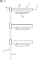
- figure 2 12 shows contacting elements 17 designed as shields and a common drive 27 for the contacting elements 17.
- Each shield is designed to shield the power converter modules 3 of a module group 5 to 7.
- Each shielding has a shielding tube 29 and is rotatable about an axis of rotation 31, which is a longitudinal axis of the shielding tube 29, between its two end positions.
- a shielding contact 33 projects from each shielding tube 29 and is designed as a handle arranged on the shielding tube 29 .
- the shields are made of aluminum, for example.
- the drive 27 comprises a drive rod 35, which can be rotated about its longitudinal axis, driven manually, mechanically or electrically, and for each shielding tube 29 a gear element 37, which causes the shielding tube 29 to rotate about the axis of rotation 31 from a rotation of the drive rod 35 about its longitudinal axis .
- the drive rod 35 and each gear element 37 form a worm gear, with the drive rod 35 being designed as a worm of the worm gear and the gear element 37 being designed as a worm wheel of the worm gear.
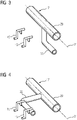
- the Figures 3 and 4 show two pole contacts 15 of a module group 5 to 7 and a portion of an associated shield in the two end positions of the shield, wherein figure 3 shows the first end position and figure 4 shows the second end position.
- the pole contacts 15 of the module group 5 to 7 are arranged next to one another along a parallel to the axis of rotation 31 of the shield.
- the shield contact 33 of the shield is at a distance from the pole contacts 15 .
- the shielding tube 29 is rotated by approximately 90 degrees about the axis of rotation 31 and the first end position Shielding contact 33 of the shielding rests against the pole contacts 15.
- the figures 5 and 6 show pole contacts 15 and a contacting element 17 designed as an electrically conductive contact cable, which is guided on an electrically insulating guide cable 39 .
- the guide cable 39 is guided over a first cable drum 41 , deflection rollers 43 , the pole contacts 15 and a grounding contact 19 .
- the contact cable In its first end position, the contact cable is wound up on a second cable drum 42 and is guided by the guide cable 39 from the first end position via an in figure 5 intermediate layer shown in the in figure 6 drawn second end position shown, in which it rests on all pole contacts 15 and the grounding contact 19.
- the contact cable is made of copper, for example.
- the cable drums 41, 42 are mounted on a drive shaft 45 which can be driven manually, mechanically or electrically.
Landscapes
- Engineering & Computer Science (AREA)
- Power Engineering (AREA)
- Physics & Mathematics (AREA)
- Electromagnetism (AREA)
- Inverter Devices (AREA)
- Rectifiers (AREA)
- Power Conversion In General (AREA)
Description
- Die Erfindung betrifft einen modularen Multilevel-Stromrichter mit mehreren Stromrichtermodulen, die jeweils eine Gleichspannungsquelle, beispielsweise einen Kondensator, aufweisen.
- Um Wartungsarbeiten an einem solchen Stromrichter auszuführen, muss vorher sichergestellt sein, dass die Gleichspannungsquellen entladen sind und mindestens ein Pol jeder Gleichspannungsquelle auf Erdpotential liegt. Beispielsweise wird die Potentialanbindung über eine hohe Anzahl in Reihe geschalteter Schiebekontakte oder durch von Hand eingelegte Überbrückungsseile erreicht. Die hohe Anzahl von in Reihe geschalteten Kontakten kann bei Ausfall von zwei Kontakten jedoch zu einer Unterbrechung des Erdpotentials führen.
- Aus der internationalen Patentanmeldung
WO 2008/074275 A1 ist eine Erdungsvorrichtung mit einem aufwickelbaren Überbrückungsseil bekannt, welches einen Isolierabschnitt und einen Erdungsabschnitt aufweist. Bei Bedarf wird der Erdungsabschnitt über die Stromrichtermodule gezogen. - Der Erfindung liegt die Aufgabe zugrunde, ein Potentialausgleichsystem für einen modularen Multilevel-Stromrichter mit mehreren Stromrichtermodulen, die jeweils eine Gleichspannungsquelle aufweisen, anzugeben, das die Anbindbarkeit der Gleichspannungsquellen an ein Erdpotential verbessert.
- Die Aufgabe wird erfindungsgemäß durch ein Potentialausgleichsystem mit den Merkmalen des Anspruchs 1 und einen modularen Multilevel-Stromrichter mit den Merkmalen des Anspruchs 9 gelöst.
- Vorteilhafte Ausgestaltungen der Erfindung sind Gegenstand der Unteransprüche.
- Ein erfindungsgemäßes Potentialausgleichsystem für einen modularen Multilevel-Stromrichter, der mehrere Stromrichtermodule (3) mit jeweils einer Gleichspannungsquelle (13) aufweist, umfasst Polkontakte, die jeweils mit einem Pol einer Gleichspannungsquelle elektrisch verbunden sind, und wenigstens ein elektrisch leitfähiges Kontaktierelement, das zwischen einer ersten Endlage, in der es von den Stromrichtermodulen elektrisch getrennt ist, und einer zweiten Endlage, in der es Polkontakte verschiedener Gleichspannungsquellen kontaktiert und auf ein Erdpotential legbar ist, bewegbar ist, beispielsweise durch einen manuellen, mechanischen oder elektrischen Antrieb.
- Bei einem erfindungsgemäßen Potentialausgleichsystem für einen modularen Multilevel-Stromrichter können also Pole von Gleichspannungsquellen verschiedener Stromrichtermodule des Stromrichters auf ein Erdpotential gelegt werden, indem mit den Polen jeweils verbundene Polkontakte durch ein Kontaktierelement elektrisch miteinander verbunden werden und das Kontaktierelement auf das Erdpotential gelegt wird. Dadurch bleiben bei einem Ausfall einzelner Polkontakte die über die anderen Polkontakte mit dem Kontaktierelement verbundenen Gleichspannungsquellen an das Erdpotential angeschlossen. Dies erhöht vorteilhaft die Sicherheit der Anbindung vieler Gleichspannungsquellen an das Erdpotential gegenüber einer Anbindung über eine Vielzahl in Reihe geschalteter Kontakte.
- Die Erfindung sieht vor, dass wenigstens ein Kontaktierelement eine elektrische Abschirmung zum Abschirmen mehrerer Stromrichtermodule ist, die um eine Drehachse zwischen der ersten Endlage und der zweiten Endlage drehbar ist. Beispielsweise weist die Abschirmung ein Abschirmrohr auf, von dem wenigstens ein Abschirmkontakt absteht, der in der zweiten Endlage der Abschirmung wenigstens einen Polkontakt kontaktiert, und die Drehachse der Abschirmung ist eine Längsachse des Abschirmrohrs. Beispielsweise ist wenigstens ein Abschirmkontakt als ein an dem Abschirmrohr angeordneter Henkel ausgebildet, der in der zweiten Endlage der Abschirmung mehrere Polkontakte kontaktiert. Die Abschirmung ist beispielsweise aus Aluminium gefertigt.
- Die vorgenannten Ausgestaltungen der Erfindung nutzen eine in der Regel ohnehin erforderliche Abschirmung von Stromrichtermodulen als ein Kontaktierelement beziehungsweise versehen das Kontaktierelement mit einer Abschirmfunktion. Dadurch wird der Material- und Konstruktionsaufwand gegenüber separat ausgeführten Abschirmungen und Kontaktierelementen vorteilhaft reduziert.
- Eine weitere Ausgestaltung der Erfindung sieht vor, dass wenigstens ein Kontaktierelement ein elektrisch leitfähiges Kontaktseil, beispielsweise ein Kupferseil, ist, das an einem elektrisch isolierenden, über Polkontakte verschiedener Gleichspannungsquellen geführten Führungsseil führbar ist, in der ersten Endlage an keinem Polkontakt anliegt und in der zweiten Endlage an den Polkontakten, über die das Führungsseil geführt ist, anliegt. Beispielsweise ist das Führungsseil über eine erste Seiltrommel geführt, das Kontaktseil ist über eine zweite Seiltrommel geführt und beide Seiltrommeln sind auf einer manuell, mechanisch oder elektrisch antreibbaren Antriebswelle montiert.
- Ein als Kontaktseil ausgebildetes Kontaktierelement ermöglicht eine der räumlichen Verteilung der Polkontakte flexibel anpassbare elektrische Verbindung der Polkontakte, insbesondere auch eine Verbindung räumlich relativ weit voneinander entfernter Polkontakte.
- Ein erfindungsgemäßer modularer Multilevel-Stromrichter, insbesondere ein selbstgeführter modularer Multilevel-Stromrichter, umfasst mehrere Stromrichtermodule mit jeweils einer Gleichspannungsquelle, die beispielsweise als ein Kondensator oder eine elektrische Verschaltung mehrerer Kondensatoren ausgebildet ist, und ein erfindungsgemäßes Potentialausgleichsystem. Die Vorteile eines derartigen Stromrichters ergeben sich aus den oben bereits genannten Vorteilen eines erfindungsgemäßen Potentialausgleichsystems und werden daher hier nicht noch einmal aufgeführt.
- Bei einer weiteren Ausgestaltung der Erfindung weist der Stromrichter mehrere Modulgruppen auf, die jeweils mehrere Stromrichtermodule mit jeweils wenigstens einem Polkontakt aufweisen. Für jede Modulgruppe weist das Potentialausgleichsystem ein Kontaktierelement auf, das in seiner zweiten Endlage alle Polkontakte der Modulgruppe kontaktiert. Diese Ausgestaltung der Erfindung berücksichtigt, dass die Stromrichtermodule eines modularen Multilevel-Stromrichters häufig mehrere Modulgruppen bilden, die beispielsweise räumlich voneinander beabstandet angeordnet sind. In diesem Fall kann es vorteilhaft sein, für jede Modulgruppe ein Kontaktierelement vorzusehen. Dabei kann vorgesehen sein, dass alle Kontaktierelemente in ihren zweiten Endlagen elektrisch miteinander verbunden sind. Dies vereinfacht vorteilhaft die Anbindung an das Erdpotential. Ferner kann ein gemeinsamer Antrieb vorgesehen sein, mit dem alle Kontaktierelemente gleichzeitig antreibbar sind. Dadurch kann einerseits der Kosten- und Materialaufwand für das Bewegen der Kontaktierelemente reduziert werden und andererseits können die Bewegungen der Kontaktierelemente einfacher synchronisiert werden.
- Die oben beschriebenen Eigenschaften, Merkmale und Vorteile dieser Erfindung sowie die Art und Weise, wie diese erreicht werden, werden klarer und deutlicher verständlich im Zusammenhang mit der folgenden Beschreibung von Ausführungsbeispielen, die im Zusammenhang mit den Zeichnungen näher erläutert werden. Dabei zeigen:
-
FIG 1 einen Schaltplan eines modularen Multilevel-Stromrichters, -
FIG 2 als Abschirmungen ausgebildete Kontaktierelemente und einen Antrieb zum Bewegen der Abschirmungen, -
FIG 3 eine perspektivische Darstellung von Polkontakten und eines als Abschirmung ausgebildeten Kontaktierelements in einer ersten Endlage der Abschirmung, -
FIG 4 eine perspektivische Darstellung der inFigur 3 gezeigten Polkontakte und der Abschirmung in einer zweiten Endlage der Abschirmung, -
FIG 5 Polkontakte und ein als ein Kontaktseil ausgebildetes Kontaktierelement, das an einem Führungsseil geführt wird, in einer Zwischenlage des Kontaktseils, -
FIG 6 die inFigur 5 gezeigten Polkontakte und das an dem Führungsseil geführte Kontaktseil in einer zweiten Endlage des Kontaktseils. - Einander entsprechende Teile sind in den Figuren mit den gleichen Bezugszeichen versehen.
-
Figur 1 zeigt einen Schaltplan eines selbstgeführten modularen Multilevel-Stromrichters 1. Der Stromrichter 1 weist mehrere im Normalbetrieb des Stromrichters 1 in Reihe geschaltete Stromrichtermodule 3 auf, von denen nur einige dargestellt sind. Die Stromrichtermodule 3 bilden drei übereinander angeordnete Modulgruppen 5 bis 7. Ferner weist der Stromrichter 1 ein erfindungsgemäßes Potentialausgleichsystem auf, das für jede Modulgruppe 5 bis 7 ein elektrisch leitfähiges Kontaktierelement 17 und für jedes Stromrichtermodul 3 einen Polkontakt 15 aufweist. - Jedes Stromrichtermodul 3 weist eine Halbbrücke aus Halbleiterschaltern 9 auf, die beispielsweise jeweils als ein Bipolartransistor mit isoliertem Gate (IGBT = Insulated-Gate Bipolar Transistor) ausgebildet sind, zu dem eine Freilaufdiode 11 antiparallel geschaltet ist. Ferner weist jedes Stromrichtermodul 3 eine Gleichspannungsquelle 13 auf, die als ein Kondensator ausgebildet ist. Ein Pol der Gleichspannungsquelle 13 ist mit dem Polkontakt 15 des Stromrichtermoduls 3 elektrisch verbunden, über den der Pol elektrisch kontaktierbar ist.
- Das Kontaktierelement 17 jeder Modulgruppe 5 bis 7 ist zwischen einer ersten Endlage, in der es von den Stromrichtermodulen 3 der Modulgruppe 5 bis 7 elektrisch getrennt ist, und einer zweiten Endlage, in der es alle Polkontakte 15 der Modulgruppe 5 bis 7 kontaktiert und die Gleichspannungsquellen 13 der Stromrichtermodule 3 der Modulgruppe 5 bis 7 parallel schaltet, bewegbar. Das Kontaktierelement 17 einer ersten Modulgruppe 5 kontaktiert in seiner zweiten Endlage zusätzlich einen Erdungskontakt 19, an den über einen ersten Erdungsschalter 21 ein Erdpotential legbar ist. Das Kontaktierelement 17 einer zweiten Modulgruppe 6 kontaktiert in seiner zweiten Endlage zusätzlich einen ersten Verbindungskontakt 23, der elektrisch mit einem Polkontakt 15 der ersten Modulgruppe 5 verbunden ist. Das Kontaktierelement 17 der dritten Modulgruppe 7 kontaktiert in seiner zweiten Endlage zusätzlich einen zweiten Verbindungskontakt 25, der elektrisch mit einem Polkontakt 15 der zweiten Modulgruppe 6 verbunden ist. An einen Polkontakt 15 der dritten Modulgruppe 7 ist über einen zweiten Erdungsschalter 22 das Erdpotential legbar. Wenn sich alle Kontaktierelemente 17 in ihrer zweiten Endlage befinden, ist daher durch Schließen wenigstens eines Erdungsschalters 21, 22 das Erdpotential an alle Polkontakte 15 legbar.
- Jedes Kontaktierelement 17 ist über einen Antrieb 27 zwischen seinen beiden Endlagen bewegbar. Die Antriebe 27 der Kontaktierelemente 17 können auch als ein gemeinsamer Antrieb 27 für alle Kontaktierelemente 17 ausgeführt sein.
-
Figur 2 zeigt als Abschirmungen ausgebildete Kontaktierelemente 17 und einen gemeinsamen Antrieb 27 für die Kontaktierelemente 17. Jede Abschirmung ist zum Abschirmen der Stromrichtermodule 3 einer Modulgruppe 5 bis 7 ausgebildet. - Jede Abschirmung weist ein Abschirmrohr 29 auf und ist um eine Drehachse 31, die eine Längsachse des Abschirmrohrs 29 ist, zwischen seinen beiden Endlagen drehbar. Von jedem Abschirmrohr 29 steht ein Abschirmkontakt 33 ab, der als ein an dem Abschirmrohr 29 angeordneter Henkel ausgebildet ist. Die Abschirmungen sind beispielsweise aus Aluminium gefertigt.
- Der Antrieb 27 umfasst eine Antriebsstange 35, die manuell, mechanisch oder elektrisch angetrieben um ihre Längsachse drehbar ist, und für jedes Abschirmrohr 29 ein Getriebeelement 37, das aus einer Drehung der Antriebsstange 35 um deren Längsachse eine Drehung des Abschirmrohrs 29 um die Drehachse 31 bewirkt. Beispielsweise bilden die Antriebsstange 35 und jedes Getriebeelement 37 ein Schneckengetriebe, wobei die Antriebsstange 35 als Schnecke des Schneckengetriebes ausgebildet ist und das Getriebeelement 37 als Schneckenrad des Schneckengetriebes ausgebildet ist.
- Die
Figuren 3 und 4 zeigen zwei Polkontakte 15 einer Modulgruppe 5 bis 7 und einen Abschnitt einer dazu gehörenden Abschirmung in den beiden Endlagen der Abschirmung, wobeiFigur 3 die erste Endlage zeigt undFigur 4 die zweite Endlage zeigt. Die Polkontakte 15 der Modulgruppe 5 bis 7 sind entlang einer Parallelen zu der Drehachse 31 der Abschirmung nebeneinander angeordnet. In der ersten Endlage der Abschirmung ist der Abschirmkontakt 33 der Abschirmung von den Polkontakten 15 beabstandet. In der zweiten Endlage ist das Abschirmrohr 29 gegenüber der ersten Endlage um etwa 90 Grad um die Drehachse 31 gedreht und der Abschirmkontakt 33 der Abschirmung liegt an den Polkontakten 15 an. - Die
Figuren 5 und6 zeigen Polkontakte 15 und ein als ein elektrisch leitfähiges Kontaktseil ausgebildetes Kontaktierelement 17, das an einem elektrisch isolierenden Führungsseil 39 geführt wird. - Das Führungsseil 39 ist über eine erste Seiltrommel 41, Umlenkrollen 43, die Polkontakte 15 und einen Erdungskontakt 19 geführt.
- Das Kontaktseil ist in seiner ersten Endlage auf einer zweiten Seiltrommel 42 aufgewickelt und wird mit dem Führungsseil 39 von der ersten Endlage über eine in
Figur 5 gezeigte Zwischenlage in die inFigur 6 gezeigte zweite Endlage gezogen, in der es an allen Polkontakten 15 und dem Erdungskontakt 19 anliegt. Das Kontaktseil ist beispielsweise aus Kupfer gefertigt. - Die Seiltrommeln 41, 42 sind auf einer Antriebswelle 45 montiert, die manuell, mechanisch oder elektrisch antreibbar ist.
- Obwohl die Erfindung im Detail durch bevorzugte Ausführungsbeispiele näher illustriert und beschrieben wurde, so ist die Erfindung nicht durch die offenbarten Beispiele eingeschränkt und andere Variationen können vom Fachmann hieraus abgeleitet werden, ohne den Schutzumfang der Erfindung zu verlassen.
-
- 1
- Stromrichter
- 3
- Stromrichtermodul
- 5 bis 7
- Modulgruppe
- 9
- Halbleiterschalter
- 11
- Freilaufdiode
- 13
- Gleichspannungsquelle
- 15
- Polkontakt
- 17
- Kontaktierelement
- 19
- Erdungskontakt
- 21, 22
- Erdungsschalter
- 23, 25
- Verbindungskontakt
- 27
- Antrieb
- 29
- Abschirmrohr
- 31
- Drehachse
- 33
- Abschirmkontakt
- 35
- Antriebsstange
- 37
- Getriebeelement
- 39
- Führungsseil
- 41, 42
- Seiltrommel
- 43
- Umlenkrolle
- 45
- Antriebswelle
Claims (14)
- Potentialausgleichsystem für einen modularen Multilevel-Stromrichter (1), der mehrere Stromrichtermodule (3) mit jeweils einer Gleichspannungsquelle (13) aufweist, das Potentialausgleichsystem umfassend- Polkontakte (15), die jeweils mit einem Pol einer Gleichspannungsquelle (13) elektrisch verbunden sind, und- wenigstens ein elektrisch leitfähiges Kontaktierelement (17), das zwischen einer ersten Endlage, in der es von den Stromrichtermodulen (3) elektrisch getrennt ist, und einer zweiten Endlage, in der es Polkontakte (15) verschiedener Gleichspannungsquellen (13) kontaktiert und auf ein Erdpotential legbar ist, bewegbar ist,dadurch gekennzeichnet, dass
wenigstens eines der Kontaktierelemente (17) eine elektrische Abschirmung zum Abschirmen mehrerer Stromrichtermodule (3) ist, die um eine Drehachse (31) zwischen der ersten Endlage und der zweiten Endlage drehbar ist. - Potentialausgleichsystem nach Anspruch 1 mit einem manuellen, mechanischen oder elektrischen Antrieb (27) zum Bewegen des wenigstens einen Kontaktierelements (17) zwischen seinen beiden Endlagen.
- Potentialausgleichsystem nach Anspruch 1 oder 2, wobei die Abschirmung ein Abschirmrohr (29) aufweist, von dem wenigstens ein Abschirmkontakt (33) absteht, der in der zweiten Endlage der Abschirmung wenigstens einen Polkontakt (15) kontaktiert, und die Drehachse (31) der Abschirmung eine Längsachse des Abschirmrohrs (29) ist.
- Potentialausgleichsystem nach Anspruch 3, wobei wenigstens ein Abschirmkontakt (33) als ein an dem Abschirmrohr (29) angeordneter Henkel ausgebildet ist, der in der zweiten Endlage der Abschirmung mehrere Polkontakte (15) kontaktiert.
- Potentialausgleichsystem nach einem der vorhergehenden Ansprüche, wobei die Abschirmung aus Aluminium gefertigt ist.
- Potentialausgleichsystem nach einem der vorhergehenden Ansprüche, wobei wenigstens ein Kontaktierelement (17) ein elektrisch leitfähiges Kontaktseil ist, das an einem elektrisch isolierenden, über Polkontakte (15) verschiedener Gleichspannungsquellen (13) geführten Führungsseil (39) führbar ist, in der ersten Endlage an keinem Polkontakt (15) anliegt und in der zweiten Endlage an den Polkontakten (15), über die das Führungsseil (39) geführt ist, anliegt.
- Potentialausgleichsystem nach Anspruch 6, wobei das Kontaktseil aus Kupfer gefertigt ist.
- Potentialausgleichsystem nach Anspruch 6 oder 7, wobei das Führungsseil (39) über eine erste Seiltrommel (41) geführt ist, das Kontaktseil über eine zweite Seiltrommel (42) geführt ist und beide Seiltrommeln (41, 42) auf einer manuell, mechanisch oder elektrisch antreibbaren Antriebswelle (45) montiert sind.
- Modularer Multilevel-Stromrichter (1), umfassend- mehrere Stromrichtermodule (3) mit jeweils einer Gleichspannungsquelle (13) und- ein gemäß einem der vorhergehenden Ansprüche ausgebildetes Potentialausgleichsystem.
- Modularer Multilevel-Stromrichter (1) nach Anspruch 9, wobei jede Gleichspannungsquelle (13) als ein Kondensator oder eine elektrische Verschaltung mehrerer Kondensatoren ausgebildet ist.
- Modularer Multilevel-Stromrichter (1) nach Anspruch 9 oder 10, der mehrere Modulgruppen (5 bis 7) aufweist, die jeweils mehrere Stromrichtermodule (3) mit jeweils wenigstens einem Polkontakt (15) aufweisen, und dessen Potentialausgleichsystem für jede Modulgruppe (5 bis 7) ein Kontaktierelement (17) aufweist, das in seiner zweiten Endlage alle Polkontakte (15) der Modulgruppe (5 bis 7) kontaktiert.
- Modularer Multilevel-Stromrichter (1) nach Anspruch 11, wobei alle Kontaktierelemente (17) in ihren zweiten Endlagen elektrisch miteinander verbunden sind.
- Modularer Multilevel-Stromrichter (1) nach Anspruch 11 oder 12 mit einem gemeinsamen Antrieb (27), mit dem alle Kontaktierelemente (17) gleichzeitig antreibbar sind.
- Modularer Multilevel-Stromrichter (1) nach einem der Ansprüche 9 bis 13, der als ein selbstgeführter Stromrichter ausgebildet ist.
Priority Applications (1)
| Application Number | Priority Date | Filing Date | Title |
|---|---|---|---|
| PL18734771.1T PL3788707T3 (pl) | 2018-06-19 | 2018-06-19 | System wyrównywania potencjałów dla modułowego przekształtnika - wielopoziomowego |
Applications Claiming Priority (1)
| Application Number | Priority Date | Filing Date | Title |
|---|---|---|---|
| PCT/EP2018/066230 WO2019242843A1 (de) | 2018-06-19 | 2018-06-19 | Potentialausgleichsystem für einen modularen multilevel-stromrichter |
Publications (2)
| Publication Number | Publication Date |
|---|---|
| EP3788707A1 EP3788707A1 (de) | 2021-03-10 |
| EP3788707B1 true EP3788707B1 (de) | 2022-10-12 |
Family
ID=62778890
Family Applications (1)
| Application Number | Title | Priority Date | Filing Date |
|---|---|---|---|
| EP18734771.1A Active EP3788707B1 (de) | 2018-06-19 | 2018-06-19 | Potentialausgleichsystem für einen modularen multilevel-stromrichter |
Country Status (7)
| Country | Link |
|---|---|
| US (1) | US11081972B2 (de) |
| EP (1) | EP3788707B1 (de) |
| CN (1) | CN112425055B (de) |
| CA (1) | CA3101379C (de) |
| ES (1) | ES2935353T3 (de) |
| PL (1) | PL3788707T3 (de) |
| WO (1) | WO2019242843A1 (de) |
Families Citing this family (3)
| Publication number | Priority date | Publication date | Assignee | Title |
|---|---|---|---|---|
| CN112532072B (zh) * | 2020-03-26 | 2022-03-29 | 南京南瑞继保电气有限公司 | 模块化多电平子模块、阀塔及交流耐压测试方法 |
| EP4231518A1 (de) * | 2022-02-17 | 2023-08-23 | Maschinenfabrik Reinhausen GmbH | Convertisseur et procédé de décharge d'un convertisseur |
| DE102022125675A1 (de) * | 2022-10-05 | 2024-04-11 | Maschinenfabrik Reinhausen Gmbh | Kombinierte Erdungs- und Schutzeinrichtung für einen modular aufgebauten Spannungs- und Leistungswandler |
Family Cites Families (33)
| Publication number | Priority date | Publication date | Assignee | Title |
|---|---|---|---|---|
| US3567949A (en) * | 1969-05-12 | 1971-03-02 | Pan American Petroleum Corp | System for converting well logs from analogue-to-digital information |
| DE10317735B3 (de) | 2003-04-11 | 2004-11-18 | Siemens Ag | Erdungsschalter mit einem bewegbaren Kontaktstück |
| JP4766551B2 (ja) * | 2005-10-31 | 2011-09-07 | 株式会社リコー | Ac高圧装置、画像形成装置 |
| EP2102953B1 (de) | 2006-12-21 | 2014-03-19 | Siemens Aktiengesellschaft | Erdungsvorrichtung zum erden von in einer reihe aufgestellten elektrischen bauteilen |
| DE102007033704B4 (de) * | 2007-07-17 | 2009-04-30 | Siemens Ag | Anordnung mit einem Lasttrennschalter und einem Erdungsschalter |
| EP2294684B1 (de) * | 2008-06-09 | 2013-09-04 | ABB Technology AG | Anlage zum übertragen von elektrischem strom |
| US10321585B2 (en) * | 2008-07-29 | 2019-06-11 | Hitachi, Ltd. | Power conversion apparatus and electric vehicle |
| JP4657329B2 (ja) * | 2008-07-29 | 2011-03-23 | 日立オートモティブシステムズ株式会社 | 電力変換装置および電動車両 |
| JP4988665B2 (ja) * | 2008-08-06 | 2012-08-01 | 日立オートモティブシステムズ株式会社 | 半導体装置および半導体装置を用いた電力変換装置 |
| EP2293407A1 (de) * | 2009-09-08 | 2011-03-09 | Converteam Technology Ltd | Energieübertragungs- und Verteilungssysteme |
| CN102185266B (zh) | 2011-05-13 | 2013-09-25 | 辽宁省电力有限公司辽阳供电公司 | 66kV送电线路大截面导线带电断接引方法 |
| CN103050966B (zh) * | 2012-12-07 | 2014-03-19 | 国网智能电网研究院 | 模块化多电平柔性直流输电系统的接地装置及其设计方法 |
| DE202014100277U1 (de) | 2014-01-23 | 2014-02-20 | Abb Technology Ag | Erdungsschalter |
| DE202014002953U1 (de) * | 2014-04-07 | 2015-07-09 | Stefan Goetz | Elektrisches Energiespeichersystem |
| EP3278435B1 (de) * | 2015-03-30 | 2023-10-25 | General Electric Technology GmbH | Spannungsquellenumrichter mit fehlerkontrolle |
| GB2541352B (en) * | 2015-04-30 | 2022-02-16 | Porsche Ag | Apparatus and method for an electric power supply |
| EP3091551A1 (de) * | 2015-05-06 | 2016-11-09 | ABB Technology AG | Kombinierte entladungs- und erdungsvorrichtung für hochspannungsstromwandler |
| DE102015112513A1 (de) * | 2015-07-30 | 2017-02-02 | Dr. Ing. H.C. F. Porsche Aktiengesellschaft | Matroschka-Umrichter |
| CN108432107B (zh) * | 2015-09-21 | 2020-02-28 | Abb瑞士股份有限公司 | 具有斩波电路的多电平变流器 |
| JP6481861B2 (ja) | 2015-11-10 | 2019-03-13 | 住友電装株式会社 | シールド導電路 |
| DE212015000329U1 (de) * | 2015-11-26 | 2018-06-29 | Siemens Aktiengesellschaft | Anordnung mit einem Hochspannungswiderstand |
| EP3211784B1 (de) * | 2016-02-25 | 2021-03-31 | GE Energy Power Conversion Technology Ltd | Doppel-submodul für einen modularen mehrpunktstromrichter und modularer mehrpunktstromrichter mit diesem |
| US10673352B2 (en) * | 2016-03-28 | 2020-06-02 | Mitsubishi Electric Corporation | Power conversion apparatus comprising cell blocks each including cascaded converter cells and a bypass circuit connected thereto |
| EP3236484A1 (de) | 2016-04-14 | 2017-10-25 | General Electric Technology GmbH | Äquipotenzialsystem für hvdc-wandler |
| US10917992B2 (en) * | 2017-01-13 | 2021-02-09 | Cree Fayetteville, Inc. | High power multilayer module having low inductance and fast switching for paralleling power devices |
| US11050357B2 (en) * | 2017-02-21 | 2021-06-29 | Siemens Aktiengesellschaft | Modular multilevel power converter in which electronic components of the converter are arranged on different vehicles |
| PL3580839T3 (pl) * | 2017-04-05 | 2021-07-19 | Siemens Energy Global GmbH & Co. KG | Wielofazowy przekształtnik wielostopniowy |
| EP3622621B1 (de) * | 2017-07-05 | 2021-05-26 | Siemens Energy Global GmbH & Co. KG | Multilevelstromrichter |
| DE102017213099A1 (de) * | 2017-07-28 | 2019-01-31 | Siemens Aktiengesellschaft | Stromrichtereinheit |
| US20190116778A1 (en) * | 2017-10-23 | 2019-04-25 | Thomas Joseph Lavin | Pearl-Away |
| DE102018106306B4 (de) * | 2018-03-19 | 2025-02-06 | Dr. Ing. H.C. F. Porsche Aktiengesellschaft | Fahrzeug mit einem Energiespeicher |
| US10772242B2 (en) * | 2018-04-17 | 2020-09-08 | Chongqing Jinkang New Energy Vehicle Co., Ltd. | Inverter module of an electric vehicle |
| EP3696007B1 (de) * | 2019-02-18 | 2021-10-06 | Bombardier Transportation GmbH | Anordnung zum erden eines gleichspannungszwischenkreises |
-
2018
- 2018-06-19 US US17/254,471 patent/US11081972B2/en active Active
- 2018-06-19 CN CN201880094713.5A patent/CN112425055B/zh active Active
- 2018-06-19 PL PL18734771.1T patent/PL3788707T3/pl unknown
- 2018-06-19 CA CA3101379A patent/CA3101379C/en active Active
- 2018-06-19 EP EP18734771.1A patent/EP3788707B1/de active Active
- 2018-06-19 WO PCT/EP2018/066230 patent/WO2019242843A1/de not_active Ceased
- 2018-06-19 ES ES18734771T patent/ES2935353T3/es active Active
Also Published As
| Publication number | Publication date |
|---|---|
| US11081972B2 (en) | 2021-08-03 |
| PL3788707T3 (pl) | 2023-02-06 |
| ES2935353T3 (es) | 2023-03-06 |
| US20210152081A1 (en) | 2021-05-20 |
| CN112425055A (zh) | 2021-02-26 |
| CA3101379C (en) | 2022-06-28 |
| EP3788707A1 (de) | 2021-03-10 |
| CA3101379A1 (en) | 2019-12-26 |
| WO2019242843A1 (de) | 2019-12-26 |
| CN112425055B (zh) | 2022-10-28 |
Similar Documents
| Publication | Publication Date | Title |
|---|---|---|
| EP0069693B1 (de) | Zylindrischer Behölter für eine dreipolige metallgekapselte, druckgasisolierte Hochspannungsschaltanlage | |
| EP3459170B1 (de) | Vorrichtung zur elektrischen verbindung von mindestens einem elektrischen bauelement mit einer ersten und zweiten stromschiene | |
| WO2019242843A1 (de) | Potentialausgleichsystem für einen modularen multilevel-stromrichter | |
| EP0532881A2 (de) | Vorrichtung zur elektrischen Verbindung von parallel angeordneten Stromschienen | |
| EP1501180A1 (de) | Umrichterschaltung | |
| WO2016139039A1 (de) | Elektrische kurzschliessereinrichtung | |
| DE3318344C2 (de) | Hochspannungsschaltanlage | |
| EP2976832B1 (de) | Wechselrichter mit mindestens einer wechselrichterbrücke zwischen zwei busbars | |
| DE202010017792U1 (de) | Mechanischer Schalter für einen Laststufenschalter | |
| WO2012139863A1 (de) | Leistungselektronisches schaltsystem | |
| EP4207496A1 (de) | Modulverbinder | |
| DE102016207292B4 (de) | Elektrische Schutzvorrichtung und Transformator mit einer solchen | |
| EP2102953B1 (de) | Erdungsvorrichtung zum erden von in einer reihe aufgestellten elektrischen bauteilen | |
| DE2758455C2 (de) | Gekapselter mehrpoliger Schalter, insbesondere für Mittelspannung, mit einer Erdungseinrichtung | |
| WO2017089023A1 (de) | Hochspannungsvorrichtung | |
| EP3834219B1 (de) | Gasisolierte schaltanlage | |
| DE202021106389U1 (de) | Elektrisches Gerät und Anordnung mit verbesserter Isolation einer herausgeführten Stromschiene zum Anschluss eines Kabels | |
| EP2346059A2 (de) | Vorrichtung zum schalten eines Stromkreises | |
| EP3417482B1 (de) | Elektrische einrichtung mit einer halbleiterschaltung | |
| CH653472A5 (de) | Trennschalteranordnung. | |
| WO2014161923A1 (de) | Schaltschrankanordnung mit verbundenen schutzbereichen | |
| EP3659163B1 (de) | Modulsatz für den bau von leistungsschaltern | |
| DE102018203692A1 (de) | Schaltfeld | |
| DE102007047556A1 (de) | Stromschiene sowie Stromschienensystem | |
| EP3479386A1 (de) | Hybridkabel, aufweisend einen schirm, starkstromleitungen und zumindest eine kleinspannungsleitung |
Legal Events
| Date | Code | Title | Description |
|---|---|---|---|
| STAA | Information on the status of an ep patent application or granted ep patent |
Free format text: STATUS: UNKNOWN |
|
| STAA | Information on the status of an ep patent application or granted ep patent |
Free format text: STATUS: THE INTERNATIONAL PUBLICATION HAS BEEN MADE |
|
| PUAI | Public reference made under article 153(3) epc to a published international application that has entered the european phase |
Free format text: ORIGINAL CODE: 0009012 |
|
| STAA | Information on the status of an ep patent application or granted ep patent |
Free format text: STATUS: REQUEST FOR EXAMINATION WAS MADE |
|
| 17P | Request for examination filed |
Effective date: 20201124 |
|
| AK | Designated contracting states |
Kind code of ref document: A1 Designated state(s): AL AT BE BG CH CY CZ DE DK EE ES FI FR GB GR HR HU IE IS IT LI LT LU LV MC MK MT NL NO PL PT RO RS SE SI SK SM TR |
|
| AX | Request for extension of the european patent |
Extension state: BA ME |
|
| DAV | Request for validation of the european patent (deleted) | ||
| DAX | Request for extension of the european patent (deleted) | ||
| GRAP | Despatch of communication of intention to grant a patent |
Free format text: ORIGINAL CODE: EPIDOSNIGR1 |
|
| STAA | Information on the status of an ep patent application or granted ep patent |
Free format text: STATUS: GRANT OF PATENT IS INTENDED |
|
| INTG | Intention to grant announced |
Effective date: 20220513 |
|
| GRAS | Grant fee paid |
Free format text: ORIGINAL CODE: EPIDOSNIGR3 |
|
| GRAA | (expected) grant |
Free format text: ORIGINAL CODE: 0009210 |
|
| STAA | Information on the status of an ep patent application or granted ep patent |
Free format text: STATUS: THE PATENT HAS BEEN GRANTED |
|
| AK | Designated contracting states |
Kind code of ref document: B1 Designated state(s): AL AT BE BG CH CY CZ DE DK EE ES FI FR GB GR HR HU IE IS IT LI LT LU LV MC MK MT NL NO PL PT RO RS SE SI SK SM TR |
|
| REG | Reference to a national code |
Ref country code: GB Ref legal event code: FG4D Free format text: NOT ENGLISH |
|
| REG | Reference to a national code |
Ref country code: CH Ref legal event code: EP |
|
| REG | Reference to a national code |
Ref country code: DE Ref legal event code: R096 Ref document number: 502018010824 Country of ref document: DE |
|
| REG | Reference to a national code |
Ref country code: IE Ref legal event code: FG4D Free format text: LANGUAGE OF EP DOCUMENT: GERMAN |
|
| REG | Reference to a national code |
Ref country code: AT Ref legal event code: REF Ref document number: 1524765 Country of ref document: AT Kind code of ref document: T Effective date: 20221115 |
|
| REG | Reference to a national code |
Ref country code: SE Ref legal event code: TRGR |
|
| REG | Reference to a national code |
Ref country code: LT Ref legal event code: MG9D |
|
| REG | Reference to a national code |
Ref country code: NL Ref legal event code: MP Effective date: 20221012 |
|
| REG | Reference to a national code |
Ref country code: ES Ref legal event code: FG2A Ref document number: 2935353 Country of ref document: ES Kind code of ref document: T3 Effective date: 20230306 |
|
| PG25 | Lapsed in a contracting state [announced via postgrant information from national office to epo] |
Ref country code: NL Free format text: LAPSE BECAUSE OF FAILURE TO SUBMIT A TRANSLATION OF THE DESCRIPTION OR TO PAY THE FEE WITHIN THE PRESCRIBED TIME-LIMIT Effective date: 20221012 |
|
| PG25 | Lapsed in a contracting state [announced via postgrant information from national office to epo] |
Ref country code: PT Free format text: LAPSE BECAUSE OF FAILURE TO SUBMIT A TRANSLATION OF THE DESCRIPTION OR TO PAY THE FEE WITHIN THE PRESCRIBED TIME-LIMIT Effective date: 20230213 Ref country code: NO Free format text: LAPSE BECAUSE OF FAILURE TO SUBMIT A TRANSLATION OF THE DESCRIPTION OR TO PAY THE FEE WITHIN THE PRESCRIBED TIME-LIMIT Effective date: 20230112 Ref country code: LT Free format text: LAPSE BECAUSE OF FAILURE TO SUBMIT A TRANSLATION OF THE DESCRIPTION OR TO PAY THE FEE WITHIN THE PRESCRIBED TIME-LIMIT Effective date: 20221012 Ref country code: FI Free format text: LAPSE BECAUSE OF FAILURE TO SUBMIT A TRANSLATION OF THE DESCRIPTION OR TO PAY THE FEE WITHIN THE PRESCRIBED TIME-LIMIT Effective date: 20221012 |
|
| PG25 | Lapsed in a contracting state [announced via postgrant information from national office to epo] |
Ref country code: RS Free format text: LAPSE BECAUSE OF FAILURE TO SUBMIT A TRANSLATION OF THE DESCRIPTION OR TO PAY THE FEE WITHIN THE PRESCRIBED TIME-LIMIT Effective date: 20221012 Ref country code: LV Free format text: LAPSE BECAUSE OF FAILURE TO SUBMIT A TRANSLATION OF THE DESCRIPTION OR TO PAY THE FEE WITHIN THE PRESCRIBED TIME-LIMIT Effective date: 20221012 Ref country code: IS Free format text: LAPSE BECAUSE OF FAILURE TO SUBMIT A TRANSLATION OF THE DESCRIPTION OR TO PAY THE FEE WITHIN THE PRESCRIBED TIME-LIMIT Effective date: 20230212 Ref country code: HR Free format text: LAPSE BECAUSE OF FAILURE TO SUBMIT A TRANSLATION OF THE DESCRIPTION OR TO PAY THE FEE WITHIN THE PRESCRIBED TIME-LIMIT Effective date: 20221012 Ref country code: GR Free format text: LAPSE BECAUSE OF FAILURE TO SUBMIT A TRANSLATION OF THE DESCRIPTION OR TO PAY THE FEE WITHIN THE PRESCRIBED TIME-LIMIT Effective date: 20230113 |
|
| REG | Reference to a national code |
Ref country code: DE Ref legal event code: R097 Ref document number: 502018010824 Country of ref document: DE |
|
| PG25 | Lapsed in a contracting state [announced via postgrant information from national office to epo] |
Ref country code: SM Free format text: LAPSE BECAUSE OF FAILURE TO SUBMIT A TRANSLATION OF THE DESCRIPTION OR TO PAY THE FEE WITHIN THE PRESCRIBED TIME-LIMIT Effective date: 20221012 Ref country code: RO Free format text: LAPSE BECAUSE OF FAILURE TO SUBMIT A TRANSLATION OF THE DESCRIPTION OR TO PAY THE FEE WITHIN THE PRESCRIBED TIME-LIMIT Effective date: 20221012 Ref country code: EE Free format text: LAPSE BECAUSE OF FAILURE TO SUBMIT A TRANSLATION OF THE DESCRIPTION OR TO PAY THE FEE WITHIN THE PRESCRIBED TIME-LIMIT Effective date: 20221012 Ref country code: DK Free format text: LAPSE BECAUSE OF FAILURE TO SUBMIT A TRANSLATION OF THE DESCRIPTION OR TO PAY THE FEE WITHIN THE PRESCRIBED TIME-LIMIT Effective date: 20221012 Ref country code: CZ Free format text: LAPSE BECAUSE OF FAILURE TO SUBMIT A TRANSLATION OF THE DESCRIPTION OR TO PAY THE FEE WITHIN THE PRESCRIBED TIME-LIMIT Effective date: 20221012 |
|
| PLBE | No opposition filed within time limit |
Free format text: ORIGINAL CODE: 0009261 |
|
| STAA | Information on the status of an ep patent application or granted ep patent |
Free format text: STATUS: NO OPPOSITION FILED WITHIN TIME LIMIT |
|
| PG25 | Lapsed in a contracting state [announced via postgrant information from national office to epo] |
Ref country code: SK Free format text: LAPSE BECAUSE OF FAILURE TO SUBMIT A TRANSLATION OF THE DESCRIPTION OR TO PAY THE FEE WITHIN THE PRESCRIBED TIME-LIMIT Effective date: 20221012 Ref country code: AL Free format text: LAPSE BECAUSE OF FAILURE TO SUBMIT A TRANSLATION OF THE DESCRIPTION OR TO PAY THE FEE WITHIN THE PRESCRIBED TIME-LIMIT Effective date: 20221012 |
|
| 26N | No opposition filed |
Effective date: 20230713 |
|
| PG25 | Lapsed in a contracting state [announced via postgrant information from national office to epo] |
Ref country code: SI Free format text: LAPSE BECAUSE OF FAILURE TO SUBMIT A TRANSLATION OF THE DESCRIPTION OR TO PAY THE FEE WITHIN THE PRESCRIBED TIME-LIMIT Effective date: 20221012 |
|
| PG25 | Lapsed in a contracting state [announced via postgrant information from national office to epo] |
Ref country code: MC Free format text: LAPSE BECAUSE OF FAILURE TO SUBMIT A TRANSLATION OF THE DESCRIPTION OR TO PAY THE FEE WITHIN THE PRESCRIBED TIME-LIMIT Effective date: 20221012 |
|
| PG25 | Lapsed in a contracting state [announced via postgrant information from national office to epo] |
Ref country code: MC Free format text: LAPSE BECAUSE OF FAILURE TO SUBMIT A TRANSLATION OF THE DESCRIPTION OR TO PAY THE FEE WITHIN THE PRESCRIBED TIME-LIMIT Effective date: 20221012 |
|
| REG | Reference to a national code |
Ref country code: CH Ref legal event code: PL |
|
| REG | Reference to a national code |
Ref country code: BE Ref legal event code: MM Effective date: 20230630 |
|
| PG25 | Lapsed in a contracting state [announced via postgrant information from national office to epo] |
Ref country code: LU Free format text: LAPSE BECAUSE OF NON-PAYMENT OF DUE FEES Effective date: 20230619 |
|
| REG | Reference to a national code |
Ref country code: IE Ref legal event code: MM4A |
|
| PG25 | Lapsed in a contracting state [announced via postgrant information from national office to epo] |
Ref country code: LU Free format text: LAPSE BECAUSE OF NON-PAYMENT OF DUE FEES Effective date: 20230619 |
|
| PG25 | Lapsed in a contracting state [announced via postgrant information from national office to epo] |
Ref country code: IE Free format text: LAPSE BECAUSE OF NON-PAYMENT OF DUE FEES Effective date: 20230619 |
|
| PG25 | Lapsed in a contracting state [announced via postgrant information from national office to epo] |
Ref country code: IE Free format text: LAPSE BECAUSE OF NON-PAYMENT OF DUE FEES Effective date: 20230619 Ref country code: CH Free format text: LAPSE BECAUSE OF NON-PAYMENT OF DUE FEES Effective date: 20230630 |
|
| PG25 | Lapsed in a contracting state [announced via postgrant information from national office to epo] |
Ref country code: BE Free format text: LAPSE BECAUSE OF NON-PAYMENT OF DUE FEES Effective date: 20230630 |
|
| REG | Reference to a national code |
Ref country code: AT Ref legal event code: MM01 Ref document number: 1524765 Country of ref document: AT Kind code of ref document: T Effective date: 20230619 |
|
| PG25 | Lapsed in a contracting state [announced via postgrant information from national office to epo] |
Ref country code: AT Free format text: LAPSE BECAUSE OF NON-PAYMENT OF DUE FEES Effective date: 20230619 |
|
| PG25 | Lapsed in a contracting state [announced via postgrant information from national office to epo] |
Ref country code: AT Free format text: LAPSE BECAUSE OF NON-PAYMENT OF DUE FEES Effective date: 20230619 |
|
| PG25 | Lapsed in a contracting state [announced via postgrant information from national office to epo] |
Ref country code: BG Free format text: LAPSE BECAUSE OF FAILURE TO SUBMIT A TRANSLATION OF THE DESCRIPTION OR TO PAY THE FEE WITHIN THE PRESCRIBED TIME-LIMIT Effective date: 20221012 |
|
| PG25 | Lapsed in a contracting state [announced via postgrant information from national office to epo] |
Ref country code: BG Free format text: LAPSE BECAUSE OF FAILURE TO SUBMIT A TRANSLATION OF THE DESCRIPTION OR TO PAY THE FEE WITHIN THE PRESCRIBED TIME-LIMIT Effective date: 20221012 |
|
| PGFP | Annual fee paid to national office [announced via postgrant information from national office to epo] |
Ref country code: PL Payment date: 20250603 Year of fee payment: 8 Ref country code: DE Payment date: 20250626 Year of fee payment: 8 |
|
| PGFP | Annual fee paid to national office [announced via postgrant information from national office to epo] |
Ref country code: GB Payment date: 20250617 Year of fee payment: 8 |
|
| PGFP | Annual fee paid to national office [announced via postgrant information from national office to epo] |
Ref country code: FR Payment date: 20250624 Year of fee payment: 8 |
|
| PG25 | Lapsed in a contracting state [announced via postgrant information from national office to epo] |
Ref country code: CY Free format text: LAPSE BECAUSE OF FAILURE TO SUBMIT A TRANSLATION OF THE DESCRIPTION OR TO PAY THE FEE WITHIN THE PRESCRIBED TIME-LIMIT; INVALID AB INITIO Effective date: 20180619 |
|
| PGFP | Annual fee paid to national office [announced via postgrant information from national office to epo] |
Ref country code: SE Payment date: 20250619 Year of fee payment: 8 |
|
| PG25 | Lapsed in a contracting state [announced via postgrant information from national office to epo] |
Ref country code: HU Free format text: LAPSE BECAUSE OF FAILURE TO SUBMIT A TRANSLATION OF THE DESCRIPTION OR TO PAY THE FEE WITHIN THE PRESCRIBED TIME-LIMIT; INVALID AB INITIO Effective date: 20180619 |
|
| PGFP | Annual fee paid to national office [announced via postgrant information from national office to epo] |
Ref country code: ES Payment date: 20250710 Year of fee payment: 8 |
|
| PGFP | Annual fee paid to national office [announced via postgrant information from national office to epo] |
Ref country code: IT Payment date: 20250623 Year of fee payment: 8 |
|
| PG25 | Lapsed in a contracting state [announced via postgrant information from national office to epo] |
Ref country code: TR Free format text: LAPSE BECAUSE OF FAILURE TO SUBMIT A TRANSLATION OF THE DESCRIPTION OR TO PAY THE FEE WITHIN THE PRESCRIBED TIME-LIMIT Effective date: 20221012 |