EP3788462B1 - Metal mesh assembly, touch control display panel and manufacturing thereof, and display apparatus - Google Patents
Metal mesh assembly, touch control display panel and manufacturing thereof, and display apparatus Download PDFInfo
- Publication number
- EP3788462B1 EP3788462B1 EP18905899.3A EP18905899A EP3788462B1 EP 3788462 B1 EP3788462 B1 EP 3788462B1 EP 18905899 A EP18905899 A EP 18905899A EP 3788462 B1 EP3788462 B1 EP 3788462B1
- Authority
- EP
- European Patent Office
- Prior art keywords
- lines
- layer
- sensing
- display panel
- segment
- Prior art date
- Legal status (The legal status is an assumption and is not a legal conclusion. Google has not performed a legal analysis and makes no representation as to the accuracy of the status listed.)
- Active
Links
Images


Classifications
-
- G—PHYSICS
- G06—COMPUTING OR CALCULATING; COUNTING
- G06F—ELECTRIC DIGITAL DATA PROCESSING
- G06F3/00—Input arrangements for transferring data to be processed into a form capable of being handled by the computer; Output arrangements for transferring data from processing unit to output unit, e.g. interface arrangements
- G06F3/01—Input arrangements or combined input and output arrangements for interaction between user and computer
- G06F3/03—Arrangements for converting the position or the displacement of a member into a coded form
- G06F3/041—Digitisers, e.g. for touch screens or touch pads, characterised by the transducing means
- G06F3/0416—Control or interface arrangements specially adapted for digitisers
-
- G—PHYSICS
- G06—COMPUTING OR CALCULATING; COUNTING
- G06F—ELECTRIC DIGITAL DATA PROCESSING
- G06F3/00—Input arrangements for transferring data to be processed into a form capable of being handled by the computer; Output arrangements for transferring data from processing unit to output unit, e.g. interface arrangements
- G06F3/01—Input arrangements or combined input and output arrangements for interaction between user and computer
- G06F3/03—Arrangements for converting the position or the displacement of a member into a coded form
- G06F3/041—Digitisers, e.g. for touch screens or touch pads, characterised by the transducing means
- G06F3/044—Digitisers, e.g. for touch screens or touch pads, characterised by the transducing means by capacitive means
- G06F3/0445—Digitisers, e.g. for touch screens or touch pads, characterised by the transducing means by capacitive means using two or more layers of sensing electrodes, e.g. using two layers of electrodes separated by a dielectric layer
-
- G—PHYSICS
- G06—COMPUTING OR CALCULATING; COUNTING
- G06F—ELECTRIC DIGITAL DATA PROCESSING
- G06F3/00—Input arrangements for transferring data to be processed into a form capable of being handled by the computer; Output arrangements for transferring data from processing unit to output unit, e.g. interface arrangements
- G06F3/01—Input arrangements or combined input and output arrangements for interaction between user and computer
- G06F3/03—Arrangements for converting the position or the displacement of a member into a coded form
- G06F3/041—Digitisers, e.g. for touch screens or touch pads, characterised by the transducing means
- G06F3/047—Digitisers, e.g. for touch screens or touch pads, characterised by the transducing means using sets of wires, e.g. crossed wires
-
- G—PHYSICS
- G06—COMPUTING OR CALCULATING; COUNTING
- G06F—ELECTRIC DIGITAL DATA PROCESSING
- G06F3/00—Input arrangements for transferring data to be processed into a form capable of being handled by the computer; Output arrangements for transferring data from processing unit to output unit, e.g. interface arrangements
- G06F3/01—Input arrangements or combined input and output arrangements for interaction between user and computer
- G06F3/03—Arrangements for converting the position or the displacement of a member into a coded form
- G06F3/041—Digitisers, e.g. for touch screens or touch pads, characterised by the transducing means
- G06F3/0412—Digitisers structurally integrated in a display
-
- G—PHYSICS
- G06—COMPUTING OR CALCULATING; COUNTING
- G06F—ELECTRIC DIGITAL DATA PROCESSING
- G06F3/00—Input arrangements for transferring data to be processed into a form capable of being handled by the computer; Output arrangements for transferring data from processing unit to output unit, e.g. interface arrangements
- G06F3/01—Input arrangements or combined input and output arrangements for interaction between user and computer
- G06F3/03—Arrangements for converting the position or the displacement of a member into a coded form
- G06F3/041—Digitisers, e.g. for touch screens or touch pads, characterised by the transducing means
- G06F3/0416—Control or interface arrangements specially adapted for digitisers
- G06F3/04164—Connections between sensors and controllers, e.g. routing lines between electrodes and connection pads
-
- G—PHYSICS
- G06—COMPUTING OR CALCULATING; COUNTING
- G06F—ELECTRIC DIGITAL DATA PROCESSING
- G06F2203/00—Indexing scheme relating to G06F3/00 - G06F3/048
- G06F2203/041—Indexing scheme relating to G06F3/041 - G06F3/045
- G06F2203/04103—Manufacturing, i.e. details related to manufacturing processes specially suited for touch sensitive devices
-
- G—PHYSICS
- G06—COMPUTING OR CALCULATING; COUNTING
- G06F—ELECTRIC DIGITAL DATA PROCESSING
- G06F2203/00—Indexing scheme relating to G06F3/00 - G06F3/048
- G06F2203/041—Indexing scheme relating to G06F3/041 - G06F3/045
- G06F2203/04112—Electrode mesh in capacitive digitiser: electrode for touch sensing is formed of a mesh of very fine, normally metallic, interconnected lines that are almost invisible to see. This provides a quite large but transparent electrode surface, without need for ITO or similar transparent conductive material
Definitions
- the present disclosure relates generally to the field of display technologies, and more specifically to a touch control display panel and its manufacturing method, and a display apparatus containing the touch control display panel.
- the touch detection portion is typically arranged on a front side of the touch control display panel, which detects the position where a user touches the display panel/screen and then sends the detection signal corresponding to the touch position to the touch controller.
- the touch controller converts the detection signal that has been received from the touch detection portion into coordinate data, and then transmits the coordinate data to a central processing unit. Furthermore, the touch controller can also receive a control signal returned by the central processing unit, and then can execute based on the control signal to thereby realize a human-machine interaction.
- the N-type oxide semiconductor materials such as indium tin oxide (ITO)
- ITO indium tin oxide
- the rarity of the element indium (In) the manufacturing cost of the touch control display panels employing indium is expected to rise over the future.
- a metal mesh touch control display panel which notably employs common metal materials, such as aluminum, copper, and silver, etc.
- the metal mesh touch control display panels have become one of the most popular solutions, and the metal mesh touch control display panels have characteristics such as a high touch control accuracy, and a high touch control sensitivity.
- metal mesh touch control display panels require a touch control support for an active pen, such as the active pen with a tilt function.
- active pen such as the active pen with a tilt function.
- current metal mesh touch control display panels do not meet these above needs.
- optical effect of a typical metal mesh touch control display panel is mediocre.
- US2016103520A1 discloses a touch screen panel.
- the touch screen panel includes first sensing electrodes arranged in a first direction and in first mesh patterns and second sensing electrodes arranged in a second direction crossing the first direction and in second mesh patterns. At a region where the first and second sensing electrodes overlap each other, a portion of at least one of the first and second mesh patterns is removed, such that the first and second mesh patterns are free from overlap with each other at the location where the portion is removed.
- US2016282973A1 discloses a method of designing a metal mesh touch sensor with randomized channel displace1llent.
- the method includes generating a representation of a first conductive pattern.
- the representation of the first conductive pattern is partitioned into a plurality of representations of column channels.
- a random channel displacement is applied to at least one column channel.
- a representation of a second conductive pattern is generated.
- the representation of the second conductive pattern is partitioned into a plurality of representations of row channels.
- a random channel displacement is applied to at least one row channel.
- US2015355752A1 discloses a sensor-equipped display device.
- the sensor-equipped display device inc1udes a display panel and a detection electrode.
- the display panel includes a display area in which a plurality of pixels are arranged.
- the detection electrode includes an electrode pattern having conductive line fragments arranged on a detection surface which is parallel to the display area, wherein the electrode pattern includes a connection point at which ends of three line fragments are connected together.
- the touch component includes a first metal mesh layer and a second metal mesh layer which are opposite to each other, the first metal mesh layer including a plurality of first touch channel areas, the first virtual wiring area including a plurality of first virtual wiring openings, the second metal mesh layer including a plurality of second touch channel areas and a plurality of second virtual wiring areas, the second virtual wiring area including a plurality of second virtual wiring openings.
- a projection of at least part of the first virtual wiring opening on the second metal mesh layer intersects with a grid line of the second metal mesh layer.
- the present disclosure provides a touch control display panel defined by appended claim 1.
- the present disclosure further provides a display apparatus, which is defined by appended claim 10.
- the plurality of driving lines have a pattern with the two substantially perpendicular symmetric axes
- the plurality of sensing lines have a pattern with the two substantially perpendicular symmetric axes
- the plurality of dummy lines have a pattern with the two substantially perpendicular symmetric axes.
- FIG. 3 illustrates a structure of a basic pattern in each of the plurality of composite pattern units according to some embodiments of the disclosure.
- Each of the plurality of basic patterns can be the basic pattern shown in the figure.
- the basic pattern comprises a metal frame having a diamond shape (i.e. diamond-shaped metal frame) and two metal segments crossing with each other.
- the basic pattern can be arranged to be within a rectangular region, as specifically shown in FIG. 3 .
- the diamond-shaped metal frame is configured to have each of its four corner points (i.e. D1, D2, D3, and D4 ) and each of two end points (i.e. S1 and S2, S3 and S4) of each of the two metal segments fall onto the margin of the rectangular region (shown by the largest rectangle with dotted lines).
- Each of the two metal segments is substantially a diagonal line for the rectangular region.
- the four corner points (i.e. D1, D2, D3, and D4 ) of the diamond-shaped metal frame are respectively located at the midpoints of the four sides of the rectangular region.
- the composite pattern unit includes an odd number of columns of basic patterns, which specifically has 8 rows and 5 columns.
- the diamond-shaped metal frames in the composite pattern unit are all filled with gray color.
- the diamond-shaped metal frames are formed by dummy lines 3 only, or alternatively are formed by the dummy lines 3 and the sensing lines 2 in a composite manner (i.e. together).
- the four sides of each of some diamond-shaped metal frames are formed all by the dummy lines 3, whereas the four sides of each of other diamond-shaped metal frames are formed together by dummy lines 3 and sensing lines 2.
- the two metal segments are formed by any two or all three of the dummy lines 3, the sensing lines 2, and the driving lines 1.
- the two metal segments are formed by dummy lines 3 and sensing lines 2, by dummy lines and driving lines 1, or by sensing lines and driving lines 1.
- the two metal segments are formed by dummy lines 3, sensing lines 2, and driving lines 1.
- FIG. 6 illustrates a pattern for the sensing lines 2 in the sensing layer of the metal mesh assembly according to the above embodiments of the present disclosure.
- the pattern for the sensing lines 2 also has two symmetric axes that substantially overlap with the above mentioned first symmetric axis A-A and the second symmetric axis B-B, respectively.
- Such a configuration for the pattern for the sensing lines 2 allows the composite pattern unit to have a substantially complete symmetry.
- the sub-sensing region pattern in the sensing layer described above includes a plurality of first composite patterns, arranged one after another and sequentially connected along the second symmetric axis B-B.
- FIG. 7 illustrates one of the plurality of first composite patterns shown in FIG. 6 .
- each of the plurality of first composite patterns comprises a y-shaped portion and a ⁇ -shaped portion, and an upper end part of the ⁇ -shaped portion connects a lower end part of the y-shaped portion.
- the y-shaped portion is arranged at an upper part
- the ⁇ -shaped portion is arranged at a lower part in the first composite pattern.
- the y-shaped portion comprises two segments that are arranged to have an angle therebetween (i.e. a third segment e and a fourth segment f ).
- the third segment e has a length that is shorter than that of the fourth segment f .
- the third segment e constitutes the upper left part of the y-shaped portion, and the fourth segment f constitutes the rest of the y-shaped portion.
- the third segment e connects a midpoint (i.e. connecting point X2 ) of the fourth segment f.
- the sensing layer is provided with both sensing lines 2 and dummy lines 3.
- a region in the sensing layer where the sensing lines 2 are arranged therein is a sensing region
- a region in the sensing layer where the dummy lines 3 are arranged therein is a dummy region.
- the patterns for each of the sensing region and the dummy region have a substantially complete symmetry.
- FIG. 12 illustrates a pattern for the driving lines 1 in the metal mesh assembly according to the above embodiment of the present disclosure.
- the pattern for the driving lines 1 which are in the driving layer, has two symmetric axes that substantially overlap with the first symmetric axis A-A and the second symmetric axis B-B, respectively.
- Such a configuration for the pattern for the driving lines 1 allows the composite pattern unit to have a substantially complete symmetry.
- the pattern for the driving lines 1 in the driving layer comprises a plurality of diamond-shaped patterns (i.e. termed first diamond-shaped sub-patterns hereafter) arranged in a matrix. More specifically, the plurality of first diamond-shaped sub-patterns are sequentially connected along both the horizontal direction (i.e. the first symmetric axis A-A) and the vertical direction (i.e. the second symmetric axis B-B).
- the column number of the plurality of first diamond-shaped sub-patterns formed by driving lines 1 in the driving layer is an odd number. For example, there are three columns of first diamond-shaped sub-patterns specifically shown in FIG. 12 . In other words, the second symmetric axis B-B runs through the first diamond-shaped sub-patterns in the middle column.
- FIG. 13 illustrates a pattern for the sensing lines 2 in the sensing layer of the metal mesh assembly according to the above embodiments of the present disclosure.
- the pattern for the sensing lines 2 also has two symmetric axes that substantially overlap with the above mentioned first symmetric axis A-A and the second symmetric axis B-B, respectively.
- Such a configuration for the pattern for the sensing lines 2 allows the composite pattern unit to have a substantially complete symmetry.
- the pattern for the sensing lines 2 in the sensing layer similarly also comprises a plurality of diamond-shaped patterns (i.e. termed "second diamond-shaped sub-patterns hereafter) arranged in a matrix. More specifically, the plurality of second diamond-shaped sub-patterns are sequentially connected along both the horizontal direction (i.e. the first symmetric axis A-A) and the vertical direction (i.e. the second symmetric axis B-B).
- the column number of the plurality of second diamond-shaped sub-patterns in the driving layer is an even number. For example, there are two columns of second diamond-shaped sub-patterns specifically shown in FIG. 13 . In other words, the second symmetric axis B-B does not run through any second diamond-shaped sub-patterns.
- FIG. 14 illustrates a pattern for the dummy lines 3 in the sensing layer of the metal mesh assembly according to the above embodiments of the present disclosure.
- the pattern for the dummy lines 3 also has two symmetric axes that substantially overlap with the above mentioned first symmetric axis A-A and the second symmetric axis B-B, respectively.
- Such a configuration for the pattern for the dummy lines 3 allows the composite pattern unit to have a substantially complete symmetry.
- the present disclosure further provides a touch control display panel.
- the touch control display panel includes a substrate and a metal mesh assembly disposed over the substrate.
- the metal mesh assembly can be any one of the embodiments of the metal mesh assembly as described above.
- a plurality of touch electrodes can be arranged over the substrate, and each of the plurality of touch electrodes can comprise a metal mesh assembly according to any one of the embodiments of the metal mesh assembly as described above.
- the touch control display panel can support the use of an active pen with tilt function, and additionally have excellent electric effect. It is noted that the plurality of touch electrodes can be connected with each other via bridging so as to facilitate signal transmission.
- the touch control display panel can be an add-on touch control display panel or can be a built-in touch control display panel.
- FIG. 17 illustrates a structure of an add-on touch control display panel according to some embodiments of the disclosure.
- this add-on touch control display panel substantially comprises a display panel, a metal mesh assembly layer over the display panel, and a substrate over the metal mesh assembly layer, as shown in a bottom-to-top direction in the structural diagram of the add-on touch control display panel shown in FIG. 17 .
- the display panel can be based on a current technology known to people of ordinary skills in the field, and can, according to some embodiments of the touch control display panel shown in FIG. 17 , comprise a base substrate, which can be a glass (shown as "array glass”).
- the display panel further comprises a liquid crystal layer, a color filter substrate (such as a color filter glass, shown as "CF glass”), a polarizing layer (POL), and an optically clear resin (OCR) layer, which are sequentially over the base substrate.
- a color filter substrate such as a color filter glass, shown as "CF glass”
- POL polarizing layer
- OCR optically clear resin
- the metal mesh assembly layer that is over the display panel comprises a sensing layer (shown as Rx), a first protection layer (shown as OC1), a driving layer (shown as Tx), and a second protection layer (shown as OC2), which are sequentially arranged between the substrate and the display panel and in a direction from the substrate to the display panel (i.e. top-to-bottom direction in FIG. 17 ).
- the first protection layer is between the sensing layer and the driving layer
- the second protection layer (shown as OC2) is between the driving layer and the display panel.
- the driving layer can comprise a pattern for the driving lines according to any one of the embodiments as described above.
- the sensing layer can comprise a pattern for the sensing lines.
- the dummy lines can be arranged only in the sensing layer, only in the driving layer, or partly in the sensing layer and partly in the driving layer.
- the add-on touch control display panel further comprises a black matrix layer (shown as BM in the figure), which is arranged to be at a substantially same layer as the sensing layer in the embodiment of the add-on touch control display panel shown in FIG. 17 . It is noted that the black matrix layer can optionally be arranged at a different layer as the sensing layer.
- BM black matrix layer
- FIG. 18 illustrates a structure of a built-in touch control display panel according to some embodiments of the disclosure.
- this built-in touch control display panel comprises a display panel, which comprises a base substrate (e.g. "array glass"), a liquid crystal layer, a color filter substrate (such as a color filter glass, shown as “CF glass”), a polarizing layer (POL), and an optically clear resin (OCR) layer, and a cover substrate (e.g. cover glass), which are sequentially arranged in a bottom-to-top direction in the figure.
- a base substrate e.g. "array glass”
- CF glass color filter glass
- POL polarizing layer
- OCR optically clear resin
- the built-in touch control display panel further comprises a metal mesh assembly layer between the color filter substrate and the POL of the display panel.
- the metal mesh assembly layer comprises a driving layer (shown as Tx), a first protection layer (shown as OC1), a sensing layer (shown as Rx), and a second protection layer (shown as OC2), which are sequentially arranged over the color filter substrate and below the POL of the display panel, as shown in the bottom-to-top direction in FIG. 18 .
- the driving layer can comprise a pattern for the driving lines according to any one of the embodiments as described above;
- the sensing layer can comprise a pattern for the sensing lines; and the dummy lines can be arranged only in the sensing layer, only in the driving layer, or partly in the sensing layer and partly in the driving layer.
- a top surface serves as a touch surface of the touch control display panel, and the sensing layer is preferably arranged to be relatively closer to the touch surface than the driving layer.
- the present disclosure further provides a method for manufacturing a touch control display panel.
- the touch control display panel can be based on any one of the embodiments described above.
- the touch control display panel is an add-on touch control display panel illustrated in FIG. 17 .
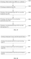
- the manufacturing method comprises the following steps: S100: forming a black matrix layer BM over a substrate.
- This step can primarily include processes such as coating, exposing and developing, to thereby form the first protection layer OC1 for the protection of the electrodes in the sensing layer Rx.
- S400 forming a driving layer Tx over the first protection layer OC1;
- the touch control display panel is a built-in touch control display panel illustrated in FIG. 18 .
- the manufacturing method comprises the following steps: S100': forming a driving layer Tx over a color film layer (CF Glass).
- This step can include processes including: depositing a metal film layer, coating a photoresist, exposing and developing, to thereby form the metallic pattern in the driving layer Tx.
- This step can include processes including: depositing a metal film layer, coating a photoresist, exposing, and developing, to thereby form the metallic pattern in the sensing layer Rx.
- S400' forming a second protection layer OC2 over the sensing layer Rx.
- a mask that is specifically designed for the step(s) can be used for the formation of relevant layers.
- the present disclosure further provides a display apparatus.
- the display apparatus comprises a touch control display panel according to any one of the embodiments as described above.
Landscapes
- Engineering & Computer Science (AREA)
- General Engineering & Computer Science (AREA)
- Theoretical Computer Science (AREA)
- Human Computer Interaction (AREA)
- Physics & Mathematics (AREA)
- General Physics & Mathematics (AREA)
- Computer Networks & Wireless Communication (AREA)
- Devices For Indicating Variable Information By Combining Individual Elements (AREA)
- Position Input By Displaying (AREA)
Applications Claiming Priority (2)
| Application Number | Priority Date | Filing Date | Title |
|---|---|---|---|
| CN201810401771.XA CN108415615B (zh) | 2018-04-28 | 2018-04-28 | 金属网格、触摸屏和显示装置 |
| PCT/CN2018/116945 WO2019205609A1 (en) | 2018-04-28 | 2018-11-22 | Metal mesh assembly, touch control display panel and manufacturing thereof, and display apparatus |
Publications (3)
| Publication Number | Publication Date |
|---|---|
| EP3788462A1 EP3788462A1 (en) | 2021-03-10 |
| EP3788462A4 EP3788462A4 (en) | 2022-01-05 |
| EP3788462B1 true EP3788462B1 (en) | 2025-03-05 |
Family
ID=63137269
Family Applications (1)
| Application Number | Title | Priority Date | Filing Date |
|---|---|---|---|
| EP18905899.3A Active EP3788462B1 (en) | 2018-04-28 | 2018-11-22 | Metal mesh assembly, touch control display panel and manufacturing thereof, and display apparatus |
Country Status (6)
| Country | Link |
|---|---|
| US (1) | US11379088B2 (https=) |
| EP (1) | EP3788462B1 (https=) |
| JP (1) | JP7248595B2 (https=) |
| KR (1) | KR102306622B1 (https=) |
| CN (1) | CN108415615B (https=) |
| WO (1) | WO2019205609A1 (https=) |
Families Citing this family (2)
| Publication number | Priority date | Publication date | Assignee | Title |
|---|---|---|---|---|
| CN108415615B (zh) * | 2018-04-28 | 2020-07-28 | 京东方科技集团股份有限公司 | 金属网格、触摸屏和显示装置 |
| WO2022267053A1 (zh) * | 2021-06-25 | 2022-12-29 | 京东方科技集团股份有限公司 | 金属网格、薄膜传感器及掩膜板 |
Citations (1)
| Publication number | Priority date | Publication date | Assignee | Title |
|---|---|---|---|---|
| CN106843625A (zh) * | 2017-01-18 | 2017-06-13 | 业成科技(成都)有限公司 | 降低可视性之金属网格结构及其制造方法 |
Family Cites Families (19)
| Publication number | Priority date | Publication date | Assignee | Title |
|---|---|---|---|---|
| JP5384598B2 (ja) | 2011-09-09 | 2014-01-08 | シャープ株式会社 | 静電容量型タッチセンサパネル、及びこれを用いた静電容量型タッチセンサシステム、情報入出力装置 |
| JP5777094B2 (ja) | 2011-07-14 | 2015-09-09 | 株式会社ワコム | 位置検出センサおよび位置検出装置 |
| KR20130128036A (ko) * | 2012-05-16 | 2013-11-26 | (주)티모스 | 터치 패널용 패드 및 제조 방법 |
| JP5849059B2 (ja) * | 2012-07-06 | 2016-01-27 | 富士フイルム株式会社 | タッチパネル用導電性フィルムおよびタッチパネル |
| CN103294294B (zh) * | 2012-08-17 | 2018-01-19 | 上海天马微电子有限公司 | 触摸感应器、内嵌式触摸液晶显示面板、液晶显示器 |
| US9304636B2 (en) * | 2013-09-20 | 2016-04-05 | Eastman Kodak Company | Micro-wire touch screen with unpatterned conductive layer |
| CN105210016B (zh) | 2013-05-16 | 2017-10-17 | 三菱制纸株式会社 | 导电图案和单层电容式触摸屏的电极图案 |
| CN103294322B (zh) * | 2013-06-06 | 2017-07-07 | 敦泰电子有限公司 | 触控显示装置 |
| JP2015143933A (ja) * | 2014-01-31 | 2015-08-06 | 株式会社ジャパンディスプレイ | 静電容量型センサ付き表示装置及びその駆動方法 |
| JP2015232819A (ja) * | 2014-06-10 | 2015-12-24 | 株式会社ジャパンディスプレイ | センサ付き表示装置 |
| KR102230808B1 (ko) * | 2014-10-13 | 2021-03-24 | 삼성디스플레이 주식회사 | 터치 스크린 패널 |
| CN104375710B (zh) * | 2014-12-04 | 2018-01-09 | 合肥鑫晟光电科技有限公司 | 一种金属网格、触摸屏和显示装置 |
| WO2016153531A1 (en) | 2015-03-24 | 2016-09-29 | Uni-Pixel Displays, Inc. | Metal mesh touch sensor with randomized channel displacement |
| KR101750428B1 (ko) * | 2015-09-24 | 2017-06-23 | 엘지디스플레이 주식회사 | 터치 스크린 일체형 표시장치 |
| CN106201145B (zh) | 2016-07-21 | 2018-10-30 | 京东方科技集团股份有限公司 | 一种触摸屏、其制作方法及显示装置 |
| JP6888077B2 (ja) * | 2017-03-06 | 2021-06-16 | 富士フイルム株式会社 | 導電性部材およびタッチパネル |
| CN107765917B (zh) | 2017-10-18 | 2021-08-27 | 京东方科技集团股份有限公司 | 一种触控面板的制备方法、触控面板和触控装置 |
| CN107831957B (zh) | 2017-11-14 | 2021-03-09 | 合肥鑫晟光电科技有限公司 | 触控组件、制作方法及一种触摸屏 |
| CN108415615B (zh) * | 2018-04-28 | 2020-07-28 | 京东方科技集团股份有限公司 | 金属网格、触摸屏和显示装置 |
-
2018
- 2018-04-28 CN CN201810401771.XA patent/CN108415615B/zh active Active
- 2018-11-22 WO PCT/CN2018/116945 patent/WO2019205609A1/en not_active Ceased
- 2018-11-22 EP EP18905899.3A patent/EP3788462B1/en active Active
- 2018-11-22 KR KR1020197026514A patent/KR102306622B1/ko active Active
- 2018-11-22 US US16/344,648 patent/US11379088B2/en active Active
- 2018-11-22 JP JP2019564809A patent/JP7248595B2/ja active Active
Patent Citations (1)
| Publication number | Priority date | Publication date | Assignee | Title |
|---|---|---|---|---|
| CN106843625A (zh) * | 2017-01-18 | 2017-06-13 | 业成科技(成都)有限公司 | 降低可视性之金属网格结构及其制造方法 |
Also Published As
| Publication number | Publication date |
|---|---|
| EP3788462A4 (en) | 2022-01-05 |
| JP7248595B2 (ja) | 2023-03-29 |
| EP3788462A1 (en) | 2021-03-10 |
| US11379088B2 (en) | 2022-07-05 |
| CN108415615A (zh) | 2018-08-17 |
| US20210365137A1 (en) | 2021-11-25 |
| JP2021519955A (ja) | 2021-08-12 |
| KR102306622B1 (ko) | 2021-09-29 |
| KR20190126327A (ko) | 2019-11-11 |
| CN108415615B (zh) | 2020-07-28 |
| WO2019205609A1 (en) | 2019-10-31 |
Similar Documents
| Publication | Publication Date | Title |
|---|---|---|
| US10222919B2 (en) | Capacitive touch screen and single layer wiring electrode array | |
| US9811221B2 (en) | Input device, method of manufacturing the same, and electronic information equipment | |
| TWI467298B (zh) | 液晶顯示裝置 | |
| EP3667476B1 (en) | Touch panel, manufacturing method therefor, and touch display device | |
| US9798430B2 (en) | Input device, method of manufacturing the same, and electronic information equipment | |
| US8717322B2 (en) | Touch panel with shield electrode | |
| CN110502152B (zh) | 触控面板、触控显示面板及触控显示装置 | |
| CN104969154A (zh) | 用于在触摸屏设备中降低可见度的网格传感器设计 | |
| JP2009211531A (ja) | 表示装置 | |
| US20110298731A1 (en) | Touch display device and touch display substrate thereof | |
| CN108196736A (zh) | 一种触控显示面板及触控显示装置 | |
| CN109885200A (zh) | 触控显示面板及触控显示器 | |
| US10139965B2 (en) | Touch panel, manufacturing method thereof and display device | |
| KR20180027399A (ko) | 터치 기판, 이를 제조하기 위한 마스크 판, 및 이의 제조 방법 | |
| CN105045453A (zh) | 一种内嵌式触摸屏及显示装置 | |
| CN107797691A (zh) | 触控显示装置 | |
| US20170177124A1 (en) | Display apparatus with touch detection function | |
| CN107844219A (zh) | 触控基板及其制作方法、显示装置 | |
| EP3788462B1 (en) | Metal mesh assembly, touch control display panel and manufacturing thereof, and display apparatus | |
| US9563324B2 (en) | Touch panel substrate, electronic device, and production method for electronic device | |
| CN112860110A (zh) | 触控显示面板 | |
| CN110018757B (zh) | 触控基板及制作方法 | |
| US11500502B2 (en) | Touch-controlling base plate and displaying device | |
| KR20150127055A (ko) | 용량형 센서 전극 | |
| US12223153B2 (en) | Display panel with same shape of grid structure of touch electrodes, leads, dummy electrodes and mobile terminal |
Legal Events
| Date | Code | Title | Description |
|---|---|---|---|
| STAA | Information on the status of an ep patent application or granted ep patent |
Free format text: STATUS: UNKNOWN |
|
| STAA | Information on the status of an ep patent application or granted ep patent |
Free format text: STATUS: THE INTERNATIONAL PUBLICATION HAS BEEN MADE |
|
| PUAI | Public reference made under article 153(3) epc to a published international application that has entered the european phase |
Free format text: ORIGINAL CODE: 0009012 |
|
| STAA | Information on the status of an ep patent application or granted ep patent |
Free format text: STATUS: REQUEST FOR EXAMINATION WAS MADE |
|
| 17P | Request for examination filed |
Effective date: 20190821 |
|
| AK | Designated contracting states |
Kind code of ref document: A1 Designated state(s): AL AT BE BG CH CY CZ DE DK EE ES FI FR GB GR HR HU IE IS IT LI LT LU LV MC MK MT NL NO PL PT RO RS SE SI SK SM TR |
|
| AX | Request for extension of the european patent |
Extension state: BA ME |
|
| DAV | Request for validation of the european patent (deleted) | ||
| DAX | Request for extension of the european patent (deleted) | ||
| A4 | Supplementary search report drawn up and despatched |
Effective date: 20211203 |
|
| RIC1 | Information provided on ipc code assigned before grant |
Ipc: G06F 3/044 20060101ALI20211129BHEP Ipc: G06F 3/041 20060101AFI20211129BHEP |
|
| STAA | Information on the status of an ep patent application or granted ep patent |
Free format text: STATUS: EXAMINATION IS IN PROGRESS |
|
| 17Q | First examination report despatched |
Effective date: 20230216 |
|
| GRAP | Despatch of communication of intention to grant a patent |
Free format text: ORIGINAL CODE: EPIDOSNIGR1 |
|
| STAA | Information on the status of an ep patent application or granted ep patent |
Free format text: STATUS: GRANT OF PATENT IS INTENDED |
|
| INTG | Intention to grant announced |
Effective date: 20241203 |
|
| GRAS | Grant fee paid |
Free format text: ORIGINAL CODE: EPIDOSNIGR3 |
|
| GRAA | (expected) grant |
Free format text: ORIGINAL CODE: 0009210 |
|
| STAA | Information on the status of an ep patent application or granted ep patent |
Free format text: STATUS: THE PATENT HAS BEEN GRANTED |
|
| AK | Designated contracting states |
Kind code of ref document: B1 Designated state(s): AL AT BE BG CH CY CZ DE DK EE ES FI FR GB GR HR HU IE IS IT LI LT LU LV MC MK MT NL NO PL PT RO RS SE SI SK SM TR |
|
| REG | Reference to a national code |
Ref country code: GB Ref legal event code: FG4D |
|
| REG | Reference to a national code |
Ref country code: CH Ref legal event code: EP |
|
| REG | Reference to a national code |
Ref country code: DE Ref legal event code: R096 Ref document number: 602018079944 Country of ref document: DE |
|
| REG | Reference to a national code |
Ref country code: IE Ref legal event code: FG4D |
|
| PG25 | Lapsed in a contracting state [announced via postgrant information from national office to epo] |
Ref country code: RS Free format text: LAPSE BECAUSE OF FAILURE TO SUBMIT A TRANSLATION OF THE DESCRIPTION OR TO PAY THE FEE WITHIN THE PRESCRIBED TIME-LIMIT Effective date: 20250605 |
|
| PG25 | Lapsed in a contracting state [announced via postgrant information from national office to epo] |
Ref country code: FI Free format text: LAPSE BECAUSE OF FAILURE TO SUBMIT A TRANSLATION OF THE DESCRIPTION OR TO PAY THE FEE WITHIN THE PRESCRIBED TIME-LIMIT Effective date: 20250305 |
|
| REG | Reference to a national code |
Ref country code: NL Ref legal event code: MP Effective date: 20250305 |
|
| PG25 | Lapsed in a contracting state [announced via postgrant information from national office to epo] |
Ref country code: ES Free format text: LAPSE BECAUSE OF FAILURE TO SUBMIT A TRANSLATION OF THE DESCRIPTION OR TO PAY THE FEE WITHIN THE PRESCRIBED TIME-LIMIT Effective date: 20250305 |
|
| REG | Reference to a national code |
Ref country code: LT Ref legal event code: MG9D |
|
| PG25 | Lapsed in a contracting state [announced via postgrant information from national office to epo] |
Ref country code: NO Free format text: LAPSE BECAUSE OF FAILURE TO SUBMIT A TRANSLATION OF THE DESCRIPTION OR TO PAY THE FEE WITHIN THE PRESCRIBED TIME-LIMIT Effective date: 20250605 |
|
| PG25 | Lapsed in a contracting state [announced via postgrant information from national office to epo] |
Ref country code: HR Free format text: LAPSE BECAUSE OF FAILURE TO SUBMIT A TRANSLATION OF THE DESCRIPTION OR TO PAY THE FEE WITHIN THE PRESCRIBED TIME-LIMIT Effective date: 20250305 |
|
| PG25 | Lapsed in a contracting state [announced via postgrant information from national office to epo] |
Ref country code: LV Free format text: LAPSE BECAUSE OF FAILURE TO SUBMIT A TRANSLATION OF THE DESCRIPTION OR TO PAY THE FEE WITHIN THE PRESCRIBED TIME-LIMIT Effective date: 20250305 |
|
| PG25 | Lapsed in a contracting state [announced via postgrant information from national office to epo] |
Ref country code: GR Free format text: LAPSE BECAUSE OF FAILURE TO SUBMIT A TRANSLATION OF THE DESCRIPTION OR TO PAY THE FEE WITHIN THE PRESCRIBED TIME-LIMIT Effective date: 20250606 Ref country code: BG Free format text: LAPSE BECAUSE OF FAILURE TO SUBMIT A TRANSLATION OF THE DESCRIPTION OR TO PAY THE FEE WITHIN THE PRESCRIBED TIME-LIMIT Effective date: 20250305 |
|
| REG | Reference to a national code |
Ref country code: AT Ref legal event code: MK05 Ref document number: 1773504 Country of ref document: AT Kind code of ref document: T Effective date: 20250305 |
|
| PG25 | Lapsed in a contracting state [announced via postgrant information from national office to epo] |
Ref country code: NL Free format text: LAPSE BECAUSE OF FAILURE TO SUBMIT A TRANSLATION OF THE DESCRIPTION OR TO PAY THE FEE WITHIN THE PRESCRIBED TIME-LIMIT Effective date: 20250305 |
|
| PG25 | Lapsed in a contracting state [announced via postgrant information from national office to epo] |
Ref country code: SE Free format text: LAPSE BECAUSE OF FAILURE TO SUBMIT A TRANSLATION OF THE DESCRIPTION OR TO PAY THE FEE WITHIN THE PRESCRIBED TIME-LIMIT Effective date: 20250305 |
|
| PG25 | Lapsed in a contracting state [announced via postgrant information from national office to epo] |
Ref country code: SM Free format text: LAPSE BECAUSE OF FAILURE TO SUBMIT A TRANSLATION OF THE DESCRIPTION OR TO PAY THE FEE WITHIN THE PRESCRIBED TIME-LIMIT Effective date: 20250305 |
|
| PG25 | Lapsed in a contracting state [announced via postgrant information from national office to epo] |
Ref country code: PT Free format text: LAPSE BECAUSE OF FAILURE TO SUBMIT A TRANSLATION OF THE DESCRIPTION OR TO PAY THE FEE WITHIN THE PRESCRIBED TIME-LIMIT Effective date: 20250707 |
|
| PG25 | Lapsed in a contracting state [announced via postgrant information from national office to epo] |
Ref country code: IT Free format text: LAPSE BECAUSE OF FAILURE TO SUBMIT A TRANSLATION OF THE DESCRIPTION OR TO PAY THE FEE WITHIN THE PRESCRIBED TIME-LIMIT Effective date: 20250305 Ref country code: PL Free format text: LAPSE BECAUSE OF FAILURE TO SUBMIT A TRANSLATION OF THE DESCRIPTION OR TO PAY THE FEE WITHIN THE PRESCRIBED TIME-LIMIT Effective date: 20250305 |
|
| PG25 | Lapsed in a contracting state [announced via postgrant information from national office to epo] |
Ref country code: AT Free format text: LAPSE BECAUSE OF FAILURE TO SUBMIT A TRANSLATION OF THE DESCRIPTION OR TO PAY THE FEE WITHIN THE PRESCRIBED TIME-LIMIT Effective date: 20250305 |
|
| PG25 | Lapsed in a contracting state [announced via postgrant information from national office to epo] |
Ref country code: CZ Free format text: LAPSE BECAUSE OF FAILURE TO SUBMIT A TRANSLATION OF THE DESCRIPTION OR TO PAY THE FEE WITHIN THE PRESCRIBED TIME-LIMIT Effective date: 20250305 Ref country code: EE Free format text: LAPSE BECAUSE OF FAILURE TO SUBMIT A TRANSLATION OF THE DESCRIPTION OR TO PAY THE FEE WITHIN THE PRESCRIBED TIME-LIMIT Effective date: 20250305 |
|
| PG25 | Lapsed in a contracting state [announced via postgrant information from national office to epo] |
Ref country code: RO Free format text: LAPSE BECAUSE OF FAILURE TO SUBMIT A TRANSLATION OF THE DESCRIPTION OR TO PAY THE FEE WITHIN THE PRESCRIBED TIME-LIMIT Effective date: 20250305 |
|
| PG25 | Lapsed in a contracting state [announced via postgrant information from national office to epo] |
Ref country code: SK Free format text: LAPSE BECAUSE OF FAILURE TO SUBMIT A TRANSLATION OF THE DESCRIPTION OR TO PAY THE FEE WITHIN THE PRESCRIBED TIME-LIMIT Effective date: 20250305 |
|
| PG25 | Lapsed in a contracting state [announced via postgrant information from national office to epo] |
Ref country code: IS Free format text: LAPSE BECAUSE OF FAILURE TO SUBMIT A TRANSLATION OF THE DESCRIPTION OR TO PAY THE FEE WITHIN THE PRESCRIBED TIME-LIMIT Effective date: 20250705 |
|
| REG | Reference to a national code |
Ref country code: DE Ref legal event code: R097 Ref document number: 602018079944 Country of ref document: DE |
|
| PGFP | Annual fee paid to national office [announced via postgrant information from national office to epo] |
Ref country code: DE Payment date: 20251119 Year of fee payment: 8 |
|
| PLBE | No opposition filed within time limit |
Free format text: ORIGINAL CODE: 0009261 |
|
| STAA | Information on the status of an ep patent application or granted ep patent |
Free format text: STATUS: NO OPPOSITION FILED WITHIN TIME LIMIT |
|
| PG25 | Lapsed in a contracting state [announced via postgrant information from national office to epo] |
Ref country code: DK Free format text: LAPSE BECAUSE OF FAILURE TO SUBMIT A TRANSLATION OF THE DESCRIPTION OR TO PAY THE FEE WITHIN THE PRESCRIBED TIME-LIMIT Effective date: 20250305 |
|
| REG | Reference to a national code |
Ref country code: CH Ref legal event code: L10 Free format text: ST27 STATUS EVENT CODE: U-0-0-L10-L00 (AS PROVIDED BY THE NATIONAL OFFICE) Effective date: 20260114 |
|
| 26N | No opposition filed |
Effective date: 20251208 |