EP3788307B1 - Vorrichtung zum verteilen von luft - Google Patents
Vorrichtung zum verteilen von luft Download PDFInfo
- Publication number
- EP3788307B1 EP3788307B1 EP19721248.3A EP19721248A EP3788307B1 EP 3788307 B1 EP3788307 B1 EP 3788307B1 EP 19721248 A EP19721248 A EP 19721248A EP 3788307 B1 EP3788307 B1 EP 3788307B1
- Authority
- EP
- European Patent Office
- Prior art keywords
- air
- displacement elements
- housing
- longitudinal axis
- inlet opening
- Prior art date
- Legal status (The legal status is an assumption and is not a legal conclusion. Google has not performed a legal analysis and makes no representation as to the accuracy of the status listed.)
- Active
Links
Images


Classifications
-
- F—MECHANICAL ENGINEERING; LIGHTING; HEATING; WEAPONS; BLASTING
- F24—HEATING; RANGES; VENTILATING
- F24F—AIR-CONDITIONING; AIR-HUMIDIFICATION; VENTILATION; USE OF AIR CURRENTS FOR SCREENING
- F24F13/00—Details common to, or for air-conditioning, air-humidification, ventilation or use of air currents for screening
- F24F13/02—Ducting arrangements
- F24F13/0236—Ducting arrangements with ducts including air distributors, e.g. air collecting boxes with at least three openings
-
- F—MECHANICAL ENGINEERING; LIGHTING; HEATING; WEAPONS; BLASTING
- F24—HEATING; RANGES; VENTILATING
- F24F—AIR-CONDITIONING; AIR-HUMIDIFICATION; VENTILATION; USE OF AIR CURRENTS FOR SCREENING
- F24F13/00—Details common to, or for air-conditioning, air-humidification, ventilation or use of air currents for screening
- F24F13/02—Ducting arrangements
- F24F13/06—Outlets for directing or distributing air into rooms or spaces, e.g. ceiling air diffuser
- F24F13/062—Outlets for directing or distributing air into rooms or spaces, e.g. ceiling air diffuser having one or more bowls or cones diverging in the flow direction
Definitions
- the present invention relates to a device for distributing air.
- An alternative designation is, for example, air distributor.
- Air distributors are used e.g. B. in ventilation systems or in systems for temperature control of rooms of the supply, discharge or general distribution of air.
- the air can be heated for example by a heater or air conditioning or z. B. have been adjusted in relation to the moisture content.
- Such air distributors are known for example from DE 10 2008 006 021 A1 or the FR 2 965 334 A1 .
- An air distributor can also be used EP 0 639 744 A2 remove.
- a plurality of plate-shaped elements are arranged along a longitudinal axis of the chamber, which have permeable baffle surfaces and widen in the direction of flow.
- the chamber tapers conically, with the plate-shaped elements each having the same design. Overall, the distance between the wall of the chamber and the plate-shaped elements decreases along the direction of flow.
- a device for distributing air according to the preamble of claim 1 is from U.S.A. 4,876,952 famous.
- the object on which the invention is based is to propose a device for distributing air which allows essentially the same amount of air to emerge from the different air outlet openings in relation to different sides of the distributor.
- the invention solves the problem with a device for distributing air according to claim 1.
- This device has at least one housing.
- the housing has an air inlet opening and several air outlet openings.
- at least two displacement elements in an interior of the housing at least two displacement elements.
- These at least two displacement elements each have at least one (special or distinguished) sectional plane, which is designed as a sectional plane of a trumpet-shaped hollow cylinder that widens along a longitudinal axis of the housing.
- the air is distributed within the interior of the housing by the at least two displacement elements, so that essentially the same amount of air exits from the outlet openings on the different sides of the housing. If, for example, the air outlet from three sides is compared, the result is by the displacer elements each about a third of the amount of air that is introduced via the air inlet opening.
- the fact that the displacement elements are based on the shape of a hollow cylinder means that the air also flows through the displacement elements in particular.
- the at least two displacement elements are spaced apart from an inner wall of the housing in such a way that air flows around the at least two displacement elements flows around. Between the displacement elements or specifically their
- outside - and the inner wall of the housing is thus according to the invention sufficient free space so that the air can flow around the displacement elements.
- the air is thus not only guided through the displacement elements, but the air also flows around them.
- the displacement elements have their smallest outer diameter in the direction of the air inlet opening.
- air outlet openings that are located on different sides of the housing are considered for the comparison of the escaping air volumes. Similar diameters of the openings should also be considered for the comparison of the air quantities, or if there are several openings on one side, the total of the individual air quantities for the affected side is formed.
- the at least two displacement elements are rotationally symmetrical and designed as trumpet-shaped hollow cylinders that widen conically along the longitudinal axis of the housing, with the longitudinal axis preferably running through the air inlet opening.
- the at least two displacement elements each have at least two sections.
- a first section has a substantially constant diameter and a second section has an increasing diameter along the longitudinal axis.
- the diameter refers to the inner diameter and/or the outer diameter of the hollow cylinder.
- the first Section and the second section follow each other directly or indirectly, depending on the configuration.
- the displacement elements are configured identically in terms of their basic geometric shape, so that the at least two displacement elements each have a sectional plane in the manner of a sectional plane of a conically widening hollow cylinder.
- the at least two displacement elements are arranged along the longitudinal axis in such a way that they partially overlap. In this embodiment, the at least two displacement elements are partially inserted into one another along the longitudinal axis.
- the two displacement elements which are partially inserted axially into one another, do not touch.
- the at least two displacement elements are arranged without overlapping axially along the longitudinal axis, so that the at least two displacement elements follow one another axially.
- At least one displacement element is statically fixed. In this configuration, the displacement element is therefore attached in particular immovably in the housing.
- displacement elements are present, all of which are statically fixed in the housing. Due to the static fixation, it is not possible to change the shape, orientation or positioning of the displacement elements in the housing. In particular, there is no controller for mechanical actuation or conversion of the displacement elements.
- the at least two displacement elements are designed essentially the same.
- the two displacement elements differ from each other, e.g. B. in relation to their axial extent, in relation to the degree of conical expansion or in relation to the different radii of the cylinder cross sections.
- the displacement elements have the same basic shape or geometry, so that they at least have a similar appearance.
- the longitudinal axis of the housing extends from a center of the air inlet opening to a center of an air outlet opening located opposite the air inlet opening.
- the device and in particular the housing are designed symmetrically about the longitudinal axis.
- the housing is formed by two symmetrical housing shells.
- the at least two displacement elements have different end radii.
- the end radii are the radii of the respective end faces of the displacement elements with the largest cross-sectional area of the displacement element concerned.
- the end radii decrease along the longitudinal axis of the housing, starting from the air inlet opening, so that the end radii of the displacement elements become smaller starting from the air inlet opening. Specifically, this means that a displacement element located closer to the air inlet opening has a larger end radius than a subsequent displacement element located further from the air inlet opening.
- the at least two displacement elements have different inlet radii.
- the inlet radii are the radii of the respective end faces of the displacement elements with the smallest cross-sectional area of the displacement element concerned. These are therefore also the front sides, those of the air inlet opening are facing.
- the different inlet radii also serve to partially arrange the individual displacement elements one inside the other.
- the at least two displacement elements have different axial extensions. In this configuration, the displacement elements therefore have different lengths in the axial direction.
- an alternative or supplementary configuration is that the at least two displacement elements emanate from a common plane perpendicular to the longitudinal axis. In this embodiment, the displacement elements begin at the same height along the longitudinal axis of the housing.
- this configuration is associated with the displacement elements having different input radii. This allows the air to also flow between the outside of a first displacement element and the inside of a second, surrounding displacement element.
- the displacement elements have different axial extensions and/or different end radii.
- the air inlet opening in the housing is opposite one of the several air outlet openings. In this configuration, there is therefore a direct connection between the air inlet opening and an affected air outlet opening. At least one additional air outlet opening is located to the side of the connection between the air inlet opening and the aforementioned air outlet opening.
- At least one air outlet opening allows the connection to a tube for the further guidance of the air.
- the air outlet opening thus has, for example, a socket or a recess that allows a pipe to be connected.
- One configuration includes that the air inlet opening can be connected to an air-ejecting unit--in particular in terms of flow technology in relation to the air.
- the air emitting unit is a heater in one embodiment and an air conditioner in another embodiment.
- the device has at least one connection or port for connection to a corresponding counterpart of the air ejection unit.
- the device is part of an air-ejecting unit.
- the device is a part of z. B. a heater or an air conditioner as examples of the air ejecting unit.
- the housing is substantially in the shape of a cube.
- the air inlet opening and the air outlet openings are located on the respective flat sides of the cube-shaped housing.
- the housing has rounded or elliptical or at least edge-free contours.
- the housing consists of two housing halves.
- the housing halves are designed identically. The production and in particular the assembly of the device can be simplified by the housing halves.
- the 1 Figure 12 shows an embodiment of the device 1 for distributing air, connected to an air ejecting unit 5, which in the embodiment shown is a heater.
- connection is made via associated interfaces for the transmission of air, so that in particular an air outlet—not visible here—of the unit 5 is in contact with the air inlet opening of the device 1—also not visible here.
- a tube between the unit 5 and the device 1 .
- a pluggable connection is preferably provided between the device 1 and the unit 5 or a pipe.
- the housing 2 of the device 1 is designed essentially in the form of a cube with planar side surfaces and essentially the same size.
- the openings are located on the side surfaces, of which only the air outlet openings 21 can be seen here.
- the air outlet openings 21 are each connected to pipes that are used to further guide the air. Alternatively, the air outlet openings 21 can also be closed or the air flows out of them directly.
- the 2 shows that the housing 2 consists of two housing halves 2.1, 2.2--in particular identically configured here.
- the housing halves 2.1, 2.2 are preferably made of a plastic, z. B. sprayed.
- displacement elements 3 There are three displacement elements 3 which are connected to three holding webs 4 .
- the holding webs 4 In the installed state, the holding webs 4 are used to fasten the displacement elements 3 in the housing 2.
- the holding web 4, which is drawn downwards here, is connected to a circular closure plate 4.1.
- the closure plate 4.1 allows for a a fixation of the arrangement of the displacement elements 3 in the housing 2 and on the other hand closes one of the air outlet openings 21.
- several displacement elements 3 are thus connected, which together with the holding webs 4 form a unit that is inserted into the housing 2.
- the unit made up of displacement elements 3 and retaining webs 4 also has a closure plate 4.1.
- the three displacement elements 3 each have different input radii, which allows them to be plugged into one another.
- the inlet radius is in each case the radius of the section of the displacement element 3 which faces the air inlet opening.
- the axially opposite radius is the end radius, with the end radius being greater than the associated entry radius in each case.
- the displacement element 3 with the smallest input radius, which is also located in the middle here, has the greatest axial extent.
- the three displacement elements 3 start from a common plane.
- the displacement elements 3 are arranged offset one behind the other.
- the 3 shows a section through the housing 2 of the device 1 of FIG 2 .
- the lower air outlet opening 21 is closed by the closure plate 4.1 so that no air escapes at this point. Nevertheless, approximately one fifth of the air that enters via the air inlet opening 20 would also exit through this air outlet opening 21 .
- the three displacement elements 3 are each rotationally symmetrical hollow cylinders with a circular cross section. Only the sectional planes of the displacement elements 3 can be seen here, which correspond to the sectional planes of hollow cylinders—which have different dimensions here.
- the hollow cylinders which can also be described as trumpet-shaped—are arranged along the longitudinal axis 26 in such a way that they partially overlap axially.
- the displacement elements 3 are fastened to the inner wall of the interior 25 of the housing 2 via the holding webs 4.
- the displacement elements 3 each have a first tubular section 3.1 with a constant diameter. This is followed in each case by a second section 3.2, the diameter of which increases in the direction of the longitudinal axis 26.
- the three displacement elements 3 each have different input radii and also different end radii. Furthermore, the different axial extensions, ie the different lengths of the three displacement elements 3 can be seen.
- the shape and relative arrangement of the displacement elements 3 causes the inflowing air to be guided to the air outlet openings 21 essentially in equal parts.
- the displacement elements 3 are circumferentially spaced from the housing 2.
- the holding webs 4 are also designed accordingly for this purpose, so that flow around is possible or is only slightly influenced.
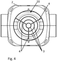
- the top view of 4 shows the three displacement elements 3 and the three holding webs 4 seen through the air inlet opening 20 of the housing 2.
- the three displacement elements 3 each have different input radii, so that they can each be arranged one inside the other.
- the holding webs 4 in pairs each enclose an angle of 120°, resulting in a symmetrical arrangement overall.
Landscapes
- Engineering & Computer Science (AREA)
- Chemical & Material Sciences (AREA)
- Combustion & Propulsion (AREA)
- Mechanical Engineering (AREA)
- General Engineering & Computer Science (AREA)
- Duct Arrangements (AREA)
- Air-Flow Control Members (AREA)
- Jet Pumps And Other Pumps (AREA)
Description
- Die vorliegende Erfindung betrifft eine Vorrichtung zum Verteilen von Luft. Eine alternative Bezeichnung ist beispielsweise Luftverteiler.
- Luftverteiler dienen z. B. in Lüftungssystemen oder in Systemen zur Temperierung von Räumen der Zuführung, Abführung oder allgemein der Verteilung von Luft. Die Luft kann dabei beispielsweise durch eine Heizung oder eine Klimaanlage erwärmt oder z. B. in Bezug auf den Feuchtigkeitsgehalt eingestellt worden sein. Solche Luftverteiler sind beispielsweise bekannt aus der
DE 10 2008 006 021 A1 oder derFR 2 965 334 A1 - Ein Luftverteiler lässt sich ebenfalls der
EP 0 639 744 A2 entnehmen. Dabei befinden sich in einer sich konisch verjüngenden Kammer mehrere Luftausströmöffnungen. Entlang einer Längsachse der Kammer sind mehrere tellerförmige Elemente angeordnet, die über durchlässige Stauflächen verfügen und sich in Strömungsrichtung aufweiten. Die Kammer verjüngt sich konisch, wobei die tellerförmigen Elemente jeweils gleich ausgeführt sind. Insgesamt nimmt somit entlang der Strömungsrichtung der Abstand zwischen der Wandung der Kammer und den tellerförmigen Elementen ab. - Eine Vorrichtung zum Verteilen von Luft gemäß dem Oberbegriff des Anspruchs 1 ist aus der
US 4 876 952 A bekannt. - Eine Problematik bei Luftverteilern besteht generell darin, dass aus den Luftausgangsöffnungen in den unterschiedlichen Richtungen jeweils unterschiedliche Luftmengen austreten. So tritt beispielsweise aus der Luftausgangsöffnung, die der Lufteingangsöffnung gegenüberliegt, eine größere Luftmenge aus als aus einer seitlich zur Lufteingangsöffnung angeordneten Luftausgangsöffnung. Solche Unterschiede machen jedoch die Planung oder Auslegung eines Luftverteilungssystems aufwendiger.
- Die der Erfindung zugrundeliegende Aufgabe besteht darin, eine Vorrichtung zum Verteilen von Luft vorzuschlagen, die es erlaubt, dass aus den unterschiedlichen Luftausgangsöffnungen bezogen auf unterschiedliche Seiten des Verteilers jeweils im Wesentlichen die gleiche Luftmenge austritt.
- Die Erfindung löst die Aufgabe durch eine Vorrichtung zum Verteilen von Luft gemäß Anspruch 1. Diese Vorrichtung weist mindestens ein Gehäuse auf.
- Dabei weist das Gehäuse eine Lufteingangsöffnung und mehrere Luftausgangsöffnungen auf. Dabei sind in einem Innenraum des Gehäuses mindestens zwei Verdrängerelemente. Diese mindestens zwei Verdrängerelemente weisen jeweils zumindest eine (besondere oder ausgezeichnete) Schnittebene auf, die als Schnittebene eines sich entlang einer Längsachse des Gehäuses aufweitenden trompetenförmigen Hohlzylinders ausgestaltet ist.
- Durch die mindestens zwei Verdrängerelemente findet die Verteilung der Luft innerhalb des Innenraums des Gehäuses statt, sodass aus den Ausgangsöffnungen auf den unterschiedlichen Seiten des Gehäuses im Wesentlichen die gleiche Luftmenge austritt. Wird also beispielsweise der Luftaustritt aus drei Seiten miteinander verglichen, so ergibt sich durch die Verdrängerelemente jeweils ungefähr ein Drittel der Luftmenge, die über die Lufteingangsöffnung eingebracht wird. Die Anlehnung der Verdrängerelemente an die Form eines Hohlzylinders führt dazu, dass die Luft insbesondere auch durch die Verdrängerelemente hindurchströmt.
- Gemäß der Erfindung sind die mindestens zwei Verdrängerelemente derartig von einer Innenwandung des Gehäuses beabstandet, dass Luft um die mindestens zwei Verdrängerelemente herumströmt. Zwischen den Verdrängerelementen oder speziell deren
- Außenseite - und der Innenwandung des Gehäuse befindet sich somit gemäß der Erfindung ausreichend Freiraum, sodass die Luft um die Verdrängerelemente herum strömen kann. Die Luft wird somit nicht nur durch die Verdrängerelemente hindurch geführt, sondern die Luft strömt auch darum herum.
- Vorzugsweise ist in einer Ausgestaltung vorgesehen, dass die Verdrängerelemente ihre kleinsten Außendurchmesser in Richtung der Lufteingangsöffnung aufweisen. Betrachtet werden für den Vergleich der austretenden Luftmengen insbesondere Luftausgangsöffnungen, die sich auf unterschiedlichen Seiten des Gehäuses befinden. Für den Vergleich der Luftmengen seien ebenfalls ähnliche Durchmesser der Öffnungen betrachtet oder es wird in dem Fall, dass sich mehrere Öffnungen auf einer Seite befinden, die Summe der einzelnen Luftmengen für die betroffene Seite gebildet.
- Gemäß der Erfindung sind die mindestens zwei Verdrängerelemente rotationssymmetrisch und als sich entlang der Längsachse des Gehäuses konisch aufweitende trompetenförmige Hohlzylinder ausgestaltet, wobei die Längsachse vorzugsweise durch die Lufteingangsöffnung verläuft.
- Gemäß einer Ausgestaltung verfügen die mindestens zwei Verdrängerelemente jeweils über mindestens zwei Abschnitte. Ein erster Abschnitt weist einen im Wesentlichen konstanten Durchmesser auf und ein zweiter Abschnitt verfügt über einen entlang der Längsachse zunehmenden Durchmesser. Der Durchmesser bezieht sich je nach Ausgestaltung auf den Innendurchmesser und/oder den Außendurchmesser des Hohlzylinders. Der erste Abschnitt und der zweite Abschnitt folgen je nach Ausgestaltung einander mittelbar oder unmittelbar.
- In einer Ausgestaltung sind die Verdrängerelemente in Bezug auf ihre grundlegende geometrische Form gleich ausgestaltet, sodass die mindestens zwei Verdrängerelemente jeweils eine Schnittebene in der Art einer Schnittebene eines sich konisch aufweitenden Hohlzylinders aufweisen.
- In einer Ausgestaltung sind die mindestens zwei Verdrängerelemente so entlang der Längsachse angeordnet, dass sie sich teilweise überlappen. In dieser Ausgestaltung stecken somit entlang der Längsachse die mindestens zwei Verdrängerelemente teilweise ineinander.
- In einer Ausgestaltung ist vorgesehen, dass die zwei teilweise axial ineinander steckenden Verdrängerelemente sich nicht berühren. In einer alternativen Ausgestaltung sind die mindestens zwei Verdrängerelemente axial entlang der Längsachse überlappungsfrei angeordnet, sodass die mindestens zwei Verdrängerelemente einander axial folgen.
- In einer Ausgestaltung ist mindestens ein Verdrängerelement statisch fixiert. Das Verdrängerelement ist somit in dieser Ausgestaltung insbesondere unbeweglich in dem Gehäuse angebracht.
- Ergänzend sind in einer weiteren Ausgestaltung mehrere Verdrängerelemente vorhanden, die alle statisch im Gehäuse fixiert sind. Durch die statische Fixierung ist somit eine Veränderung der Verdrängerelemente in Bezug auf Form, Orientierung oder Positionierung im Gehäuse nicht möglich. Insbesondere ist kein Regler für eine mechanische Betätigung oder Umstellung der Verdrängerelemente vorhanden.
- In einer Ausgestaltung sind die mindestens zwei Verdrängerelemente im Wesentlichen gleich ausgeführt. In einer alternativen Ausgestaltung unterscheiden sich die zwei Verdrängerelemente voneinander, z. B. in Bezug auf ihre axiale Erstreckung, in Bezug auf das Maß der konischen Aufweitung oder in Bezug auf die unterschiedlichen Radien der Zylinderquerschnitte. Die Verdrängerelemente haben in einer Ausgestaltung die gleiche Grundform oder Geometrie, sodass sie zumindest ein ähnliches Aussehen haben.
- In einer Ausgestaltung erstreckt sich die Längsachse des Gehäuses von einer Mitte der Lufteingangsöffnung zu einer Mitte einer der Lufteingangsöffnung gegenüber liegenden Luftausgangsöffnung.
- In einer Ausgestaltung sind die Vorrichtung und insbesondere das Gehäuse symmetrisch um die Längsachse ausgeführt. In einer Ausgestaltung wird das Gehäuse durch zwei symmetrische Gehäuseschalen gebildet.
- Gemäß einer Ausgestaltung weisen die mindestens zwei Verdrängerelemente unterschiedliche Endradien auf. Die Endradien sind dabei die Radien der jeweiligen Stirnseiten der Verdrängerelemente mit der größten Querschnittfläche des betroffenen Verdrängerelements.
- In einer Ausgestaltung nehmen die Endradien entlang der Längsachse des Gehäuses ausgehend von der Lufteingangsöffnung ab, sodass ausgehend von der Lufteingangsöffnung die Endradien der Verdrängerelemente kleiner werden. Konkret heißt dies, dass ein näher an der Lufteingangsöffnung befindliches Verdrängerelement einen größeren Endradius aufweist als ein nachfolgendes und weiter von der Lufteingangsöffnung befindliches Verdrängerelement.
- Alternativ oder ergänzend weisen gemäß einer weiteren Ausgestaltung die mindestens zwei Verdrängerelemente unterschiedliche Eingangsradien auf. Die Eingangsradien sind dabei - entsprechend zu der vorgenannten Ausgestaltung - die Radien der jeweiligen Stirnseiten der Verdrängerelemente mit der kleinsten Querschnittfläche des betroffenen Verdrängerelements. Dies sind somit auch die Stirnseiten, die der Lufteingangsöffnung zugewandt sind. Die unterschiedlichen Eingangsradien dienen auch dafür, die einzelnen Verdrängerelemente teilweise ineinander anzuordnen.
- In einer Ausgestaltung ist vorgesehen, dass die mindestens zwei Verdrängerelemente unterschiedliche axiale Erstreckungen aufweisen. In dieser Ausgestaltung haben die Verdrängerelemente somit unterschiedliche Längen in axialer Richtung.
- Eine alternative oder ergänzende Ausgestaltung besteht darin, dass die mindestens zwei Verdrängerelemente von einer gemeinsamen Ebene senkrecht zu der Längsachse ausgehen. In dieser Ausgestaltung nehmen die Verdrängerelemente ihren jeweiligen Anfang auf der gleichen Höhe entlang der Längsachse des Gehäuses.
- Diese Ausgestaltung geht in einer Ausgestaltung damit einher, dass die Verdrängerelemente unterschiedliche Eingangsradien aufweisen. Dies erlaubt, dass die Luft auch zwischen der Außenseite eines ersten Verdrängerelements und der Innenseite eines zweiten, umgebenden Verdrängerelements strömen kann. In einer zusätzlichen Ausgestaltung ist auch vorgesehen, dass die Verdrängerelemente unterschiedliche axiale Erstreckungen und/oder unterschiedliche Endradien aufweisen.
- In einer Ausgestaltung ist vorgesehen, dass in dem Gehäuse die Lufteingangsöffnung einer der mehreren Luftausgangsöffnungen gegenüberliegt. Es besteht in dieser Ausgestaltung somit eine direkte Verbindung zwischen der Lufteingangsöffnung und einer betroffenen Luftausgangsöffnung. Mindestens eine weitere Luftausgangsöffnung befindet sich dabei seitlich zu der Verbindung zwischen der Lufteingangsöffnung und der einen vorbezeichneten Luftausgansöffnung.
- In einer Ausgestaltung erlaubt mindestens eine Luftausgangsöffnung die Verbindung mit einem Rohr für die weitere Führung der Luft. Die Luftausgangsöffnung verfügt somit beispielsweise über einen Stutzen oder eine Aussparung, die einen Anschluss eines Rohrs erlaubt.
- Eine Ausgestaltung beinhaltet, dass die Lufteingangsöffnung mit einer Luft ausstoßenden Einheit - insbesondere strömungstechnisch in Bezug auf die Luft - verbindbar ist. Die Luft ausstoßende Einheit ist in einer Ausgestaltung eine Heizung und ist in einer anderen Ausgestaltung eine Klimaanlage. In dieser Ausgestaltung verfügt die Vorrichtung über mindestens eine Verbindungs- oder Anschlussstelle für eine Verbindung mit einem entsprechenden Gegenstück der Luft ausstoßenden Einheit.
- In einer Ausgestaltung ist vorgesehen, dass die Vorrichtung ein Bestandteil einer Luft ausstoßenden Einheit ist. Im Gegensatz zur vorangehenden Ausgestaltung ist hier die Vorrichtung ein Teil z. B. einer Heizung oder einer Klimaanlage als Beispiele für die Luft ausstoßende Einheit.
- Gemäß der Erfindung weist das Gehäuse im Wesentlichen die Form eines Würfels auf.
- In einer ergänzenden Ausgestaltung befinden sich die Lufteingangsöffnung und die Luftausgangsöffnungen auf den jeweils planen Seiten des würfelförmigen Gehäuses. In einer alternativen Ausgestaltung hat das Gehäuse gerundete oder elliptische oder zumindest kantenfreie Konturen. In einer Ausgestaltung befindet sich auf mindestens einer Seite des Würfels mehr als eine Luftausgangsöffnung.
- Gemäß einer Ausgestaltung besteht das Gehäuse aus zwei Gehäusehälften. In einer Ausgestaltung sind die Gehäusehälften identisch ausgestaltet. Durch die Gehäusehälften lässt sich die Fertigung und insbesondere die Montage der Vorrichtung vereinfachen.
- Im Einzelnen gibt es eine Vielzahl von Möglichkeiten, die erfindungsgemäße Vorrichtung auszugestalten und weiterzubilden. Dazu wird verwiesen einerseits auf die dem Patentanspruch 1 nachgeordneten Patentansprüche, andererseits auf die folgende Beschreibung von Ausführungsbeispielen in Verbindung mit der Zeichnung. Es zeigen:
- Fig. 1
- eine räumliche Darstellung der Vorrichtung in Verbindung mit einer Heizung,
- Fig. 2
- eine Explosionsdarstellung der Vorrichtung,
- Fig. 3
- einen Schnitt durch die in der
Fig. 2 gezeigte Vorrichtung zum Verteilen von Luft und - Fig. 4
- eine Draufsicht auf die Seite mit der Lufteingangsöffnung der LuftverteilungsVorrichtung der
Fig. 2 . - Die
Fig. 1 zeigt eine Ausgestaltung der Vorrichtung 1 zum Verteilen von Luft, die mit einer Luft ausstoßenden Einheit 5 verbunden ist, bei der es sich in dem gezeigten Ausführungsbeispiel um eine Heizung handelt. - Die Verbindung erfolgt dabei über zugehörige Schnittstellen für die Übertragung von Luft, sodass insbesondere ein - hier nicht zu sehender - Luftausgang der Einheit 5 mit der - hier ebenfalls nicht zu sehenden - Lufteingangsöffnung der Vorrichtung 1 kontaktiert ist.
- In einer alternativen - nicht dargestellten - Ausgestaltung befindet sich zwischen der Einheit 5 und der Vorrichtung 1 ein Rohr. In einer Ausführung ist vorzugsweise eine steckbare Verbindung zwischen der Vorrichtung 1 und der Einheit 5 oder einem Rohr vorgesehen.
- Das Gehäuse 2 der Vorrichtung 1 ist in der gezeigten Variante im Wesentlichen würfelförmig mit planen und im Wesentlichen gleich großen Seitenflächen ausgestaltet. Auf den Seitenflächen befinden sich die Öffnungen, von denen hier nur die Luftausgangsöffnungen 21 zu sehen sind. Insgesamt sind sechs Öffnungen vorhanden, wobei es sich um eine Lufteingangsöffnung und fünf Luftausgangsöffnungen 21 handelt.
- Durch die im Folgenden zu erläuternden Eigenschaften der Vorrichtung 1 tritt pro Seite des Gehäuses 2 jeweils ungefähr die gleiche Luftmenge aus, also ca. ein Fünftel der über die Lufteingangsöffnung eintretenden Luftmenge. An die Luftausgangsöffnungen 21 sind hier jeweils Rohre angeschlossen, die für die weitere Führung der Luft dienen. Alternativ lassen sich die Luftausgangsöffnungen 21 auch verschließen oder die Luft strömt direkt aus ihnen aus.
- Die
Fig. 2 zeigt, dass das Gehäuse 2 aus zwei - hier insbesondere identisch ausgestalteten - Gehäusehälften 2.1, 2.2 besteht. Dabei sind die Gehäusehälften 2.1, 2.2 vorzugsweise aus einem Kunststoff gefertigt, z. B. gespritzt. - Vorhanden sind drei Verdrängerelemente 3, die mit drei Haltestegen 4 verbunden sind. Die Haltestege 4 dienen im verbauten Zustand der Befestigung der Verdrängerelemente 3 in dem Gehäuse 2. Der hier zeichnerisch nach unten gerichtete Haltesteg 4 ist mit einer kreisförmigen Verschlussplatte 4.1 verbunden. Die Verschlussplatte 4.1 erlaubt zum einen eine Fixierung der Anordnung der Verdrängerelemente 3 im Gehäuse 2 und verschließt zum anderen eine der Luftausgangsöffnungen 21. In dieser Ausgestaltung sind somit mehrere Verdrängerelemente 3 verbunden, die mit den Haltestegen 4 zusammen eine Einheit bilden, die in das Gehäuse 2 eingesetzt werden. Insbesondere weist die Einheit aus Verdrängerelementen 3 und Haltestegen 4 noch eine Verschlussplatte 4.1 auf.
- Die drei Verdrängerelemente 3 haben jeweils unterschiedliche Eingangsradien, was es erlaubt, sie ineinanderzustecken. Der Eingangsradius ist dabei jeweils der Radius des Abschnitts des Verdrängerelements 3, der der Lufteingangsöffnung zugewandt ist. Der axial gegenüberliegende Radius ist der Endradius, wobei der Endradius jeweils größer als der zugehörige Eingangsradius ist.
- Das Verdrängerelement 3 mit dem kleinsten Eingangsradius, welches sich hier auch in der Mitte befindet, hat dabei die größte axiale Erstreckung.
- Weiterhin gehen die drei Verdrängerelemente 3 von einer gemeinsamen Ebene aus. In einer alternativen - nicht dargestellten - Ausgestaltung sind die Verdrängerelemente 3 versetzt hintereinander angeordnet.
- Die
Fig. 3 zeigt einen Schnitt durch das Gehäuse 2 der Vorrichtung 1 derFig. 2 . - Zu erkennen sind die Lufteingangsöffnung 20, die gegenüberliegende Luftausgangsöffnung 21 und drei weitere Luftausgangsöffnungen 21, die seitlich zur Längsachse 26 angeordnet sind und einander gegenüberliegen. Die untere Luftausgangsöffnung 21 ist durch die Verschlussplatte 4.1 verschlossen, sodass an dieser Stelle keine Luft austritt. Gleichwohl würde auch durch diese Luftausgangsöffnung 21 ungefähr ein Fünftel der Luft austreten, die über die Lufteingangsöffnung 20 eintritt.
- Für diesen Effekt, dass aus den Luftausgangsöffnungen 21 im Wesentlichen die gleiche Luftmenge austritt bzw. im geöffneten Zustand austreten würde, befinden sich in dem Innenraum 25 des Gehäuses 2 beispielhaft drei Verdrängerelemente 3. Alternativ können auch weitere oder weniger Verdrängerelemente 3 vorhanden sein.
- Die drei Verdrängerelemente 3 sind jeweils rotationssymmetrische Hohlzylinder mit kreisförmigem Querschnitt. Zu sehen sind hier somit nur die Schnittebenen der Verdrängerelemente 3, die den Schnittebenen von - hier mit unterschiedlichen Abmessungen versehenen - Hohlzylindern entsprechen.
- Die Hohlzylinder - die auch als trompetenförmig bezeichnet werden können - sind entlang der Längsachse 26 so angeordnet, dass sie sich teilweise axial überlappen. Befestigt sind die Verdrängerelemente 3 über die Haltestege 4 mit der Innenwandung des Innenraums 25 des Gehäuses 2.
- Die Verdrängerelemente 3 verfügen jeweils über einen ersten rohrförmigen Abschnitt 3.1 mit einem konstanten Durchmesser. Daran schließt sich jeweils ein zweiter Abschnitt 3.2 an, dessen Durchmesser in Richtung der Längsachse 26 größer wird. In dem gezeigten Fall verfügen die drei Verdrängerelemente 3 jeweils über unterschiedliche Eingangsradien und auch über unterschiedliche Endradien. Überdies sind die unterschiedlichen axialen Erstreckungen, also die unterschiedlichen Längen der drei Verdrängerelemente 3 zu erkennen.
- Die Luft, die durch die Lufteingangsöffnung 20 in den Innenraum 25 des Gehäuses 2 gelangt, strömt um die Verdrängerelemente 3 herum und durch diese hindurch. Die Form und relative Anordnung der Verdrängerelemente 3 bewirkt, dass die einströmende Luft im Wesentlichen zu gleichen Teilen zu den Luftausgangsöffnungen 21 geführt wird. In der gezeigten Ausgestaltung sind die Verdrängerelemente 3 umlaufend beabstandet zu dem Gehäuse 2. Dafür sind auch die Haltestege 4 entsprechend ausgestaltet, sodass ein Umströmen möglich ist bzw. nur gering beeinflusst wird.
- Die Draufsicht der
Fig. 4 zeigt durch die Lufteingangsöffnung 20 des Gehäuses 2 hindurch gesehen die drei Verdrängerelemente 3 und die drei Haltestege 4. - Die drei Verdrängerelemente 3 haben jeweils unterschiedliche Eingangsradien, sodass sie sich jeweils ineinander anordnen lassen. Die Haltestege 4 schließen paarweise jeweils einen Winkel von 120° ein, sodass sich insgesamt eine symmetrische Anordnung ergibt.
-
- 1
- Vorrichtung
- 2
- Gehäuse
- 2.1
- Gehäusehälfte
- 2.2
- Gehäusehälfte
- 3
- Verdrängerelement
- 3.1
- Erster Abschnitt
- 3.2
- Zweiter Abschnitt
- 4
- Haltesteg
- 4.1
- Verschlussplatte
- 5
- Luft ausstoßende Einheit
- 20
- Lufteingangsöffnung
- 21
- Luftausgangsöffnung
- 25
- Innenraum
- 26
- Längsachse
Claims (5)
- Vorrichtung (1) zum Verteilen von Luft,wobei die Vorrichtung (1) mindestens ein Gehäuse (2) aufweist,wobei das Gehäuse (2) eine Lufteingangsöffnung (20) und mehrere Luftausgangsöffnungen (21) aufweist,wobei in einem Innenraum (25) des Gehäuses (2) mindestens zwei Verdrängerelemente (3) angeordnet sind,wobei die mindestens zwei Verdrängerelemente (3) zumindest jeweils eine Schnittebene aufweisen, die als Schnittebene eines sich entlang einer Längsachse (26) des Gehäuses (2) aufweitenden trompetenförmigen Hohlzylinders ausgestaltet ist, undwobei die mindestens zwei Verdrängerelemente (3) derartig von einer Innenwandung des Gehäuses (2) beabstandet sind, dass Luft um die mindestens zwei Verdrängerelemente (3) herumströmt,dadurch gekennzeichnet, dass- das Gehäuse im Wesentlichen die Form eines Würfels aufweist,- sich die Luftausgangsöffnungen (21) auf unterschiedlichen Seiten des Gehäuses (2) befinden, und- die mindestens zwei Verdrängerelemente (3) rotationssymmetrisch und als sich entlang der Längsachse (26) des Gehäuses (2) konisch aufweitende trompetenförmige Hohlzylinder ausgestaltet sind.
- Vorrichtung (1) nach Anspruch 1,
wobei die mindestens zwei Verdrängerelemente (3) jeweils einen ersten Abschnitt (3.1) mit einem im Wesentlichen konstanten Durchmesser und einen zweiten Abschnitt (3.2) mit einem entlang der Längsachse (26) zunehmenden Durchmesser aufweisen. - Vorrichtung (1) nach Anspruch 1 oder 2,wobei die mindestens zwei Verdrängerelemente (3) entlang der Längsachse (26) sich teilweise überlappen,wobei die mindestens zwei Verdrängerelemente (3) unterschiedliche Endradien und/oder unterschiedliche Eingangsradien aufweisen,wobei die mindestens zwei Verdrängerelemente (3) unterschiedliche axiale Erstreckungen aufweisen, undwobei die mindestens zwei Verdrängerelemente (3) von einer gemeinsamen Ebene senkrecht zu der Längsachse (26) ausgehen.
- Vorrichtung (1) nach einem der Ansprüche 1 bis 3,
wobei die Lufteingangsöffnung (20) einer der mehreren Luftausgangsöffnungen (21) gegenüberliegt. - Vorrichtung (1) nach einem der Ansprüche 1 bis 4,wobei die Lufteingangsöffnung (20) mit einer Luft ausstoßenden Einheit (5) verbindbar ist,
und/oderwobei die Vorrichtung (1) ein Bestandteil einer Luft ausstoßenden Einheit (5) ist.
Applications Claiming Priority (2)
| Application Number | Priority Date | Filing Date | Title |
|---|---|---|---|
| DE102018003524.8A DE102018003524A1 (de) | 2018-05-02 | 2018-05-02 | Vorrichtung zum Verteilen von Luft |
| PCT/EP2019/060757 WO2019211192A1 (de) | 2018-05-02 | 2019-04-26 | Vorrichtung zum verteilen von luft |
Publications (2)
| Publication Number | Publication Date |
|---|---|
| EP3788307A1 EP3788307A1 (de) | 2021-03-10 |
| EP3788307B1 true EP3788307B1 (de) | 2022-03-09 |
Family
ID=66379898
Family Applications (1)
| Application Number | Title | Priority Date | Filing Date |
|---|---|---|---|
| EP19721248.3A Active EP3788307B1 (de) | 2018-05-02 | 2019-04-26 | Vorrichtung zum verteilen von luft |
Country Status (7)
| Country | Link |
|---|---|
| US (1) | US11796215B2 (de) |
| EP (1) | EP3788307B1 (de) |
| CN (1) | CN112088279B (de) |
| AU (1) | AU2019264287B2 (de) |
| CA (1) | CA3097936A1 (de) |
| DE (1) | DE102018003524A1 (de) |
| WO (1) | WO2019211192A1 (de) |
Families Citing this family (2)
| Publication number | Priority date | Publication date | Assignee | Title |
|---|---|---|---|---|
| CN113606765B (zh) * | 2021-09-14 | 2022-08-02 | 哈尔滨商业大学 | 一种中央空调系统用便拆式湿度控制接头装置 |
| FR3166197A1 (fr) * | 2024-09-10 | 2026-03-13 | Viessmann Climate Solutions Se | Boîtier aéraulique pour la circulation de deux flux d’air séparés et système de pompe à chaleur équipé d’un tel boîtier |
Family Cites Families (11)
| Publication number | Priority date | Publication date | Assignee | Title |
|---|---|---|---|---|
| US2380553A (en) * | 1941-03-28 | 1945-07-31 | Anemostat Corp America | Air outlet device |
| US2837990A (en) | 1950-05-11 | 1958-06-10 | Allied Thermal Corp | Air diffuser |
| US2772624A (en) * | 1952-11-06 | 1956-12-04 | W R Carnes Company | Diffuser |
| GB754734A (en) * | 1954-02-25 | 1956-08-15 | Richard Crittall And Company L | Improvements in or relating to air diffusers |
| US3087407A (en) * | 1959-09-11 | 1963-04-30 | Titus Mfg Corp | Antismudging air diffusers |
| US4750411A (en) * | 1985-03-12 | 1988-06-14 | Eversole Larry R | Register box and wye |
| US4887522A (en) * | 1987-05-22 | 1989-12-19 | Kabushiki Kaisha Kyoritsu | Air-conditioning apparatus |
| EP0639744A3 (de) | 1993-08-20 | 1995-08-16 | Renz Lukas Dipl Ing | Luftverteiler. |
| DE102008006021A1 (de) | 2007-02-19 | 2008-08-28 | Maico Elektroapparate-Fabrik Gmbh | Luftverteiler, Luftverteiler-System sowie Luftverteilungs-System |
| FR2965334B1 (fr) | 2010-09-27 | 2015-10-09 | Baillindustrie | Dispositif de type boitier de soufflerie |
| US9322561B2 (en) | 2012-02-17 | 2016-04-26 | Mitsubishi Electric Corporation | Air-conditioning apparatus and configuration of installation of same |
-
2018
- 2018-05-02 DE DE102018003524.8A patent/DE102018003524A1/de not_active Withdrawn
-
2019
- 2019-04-26 CN CN201980029344.6A patent/CN112088279B/zh active Active
- 2019-04-26 WO PCT/EP2019/060757 patent/WO2019211192A1/de not_active Ceased
- 2019-04-26 CA CA3097936A patent/CA3097936A1/en active Pending
- 2019-04-26 EP EP19721248.3A patent/EP3788307B1/de active Active
- 2019-04-26 AU AU2019264287A patent/AU2019264287B2/en active Active
- 2019-04-26 US US17/051,785 patent/US11796215B2/en active Active
Also Published As
| Publication number | Publication date |
|---|---|
| US20210123629A1 (en) | 2021-04-29 |
| CA3097936A1 (en) | 2019-11-07 |
| WO2019211192A1 (de) | 2019-11-07 |
| US11796215B2 (en) | 2023-10-24 |
| DE102018003524A1 (de) | 2019-11-07 |
| AU2019264287B2 (en) | 2024-01-04 |
| CN112088279B (zh) | 2021-12-24 |
| CN112088279A (zh) | 2020-12-15 |
| AU2019264287A1 (en) | 2020-11-26 |
| EP3788307A1 (de) | 2021-03-10 |
Similar Documents
| Publication | Publication Date | Title |
|---|---|---|
| EP2281138B1 (de) | Strömungsoptimierter rohrbogen | |
| DE3325741C1 (de) | Zylindrischer Einsatz fuer eine Zweistoff-Zerstaeubungsduese | |
| EP0132620A2 (de) | Verdampfer | |
| EP2918879B1 (de) | Mehrfachventil | |
| EP1714811A1 (de) | Luftströmer, insbesondere für ein Kraftfahrzeug | |
| EP3290246A1 (de) | Luftausströmer | |
| EP3495036A1 (de) | Mischereinsatz für statische mischer, statischer mischer sowie herstellungsverfahren | |
| EP3084163B1 (de) | Mischrohranordnung mit gehäuse | |
| DE2226745A1 (de) | Strahlgeblaese, sogenannter ejektor | |
| EP3788307A1 (de) | Vorrichtung zum verteilen von luft | |
| DE3706694A1 (de) | Zweistoff-zerstaeubungsduese zur erzeugung eines vollkegelstrahls | |
| CH678654A5 (de) | ||
| DE2323678A1 (de) | Reaktor fuer die ammoniaksynthese | |
| DE9302504U1 (de) | Kältemittelverteiler für einen Verdampfer | |
| EP2711658A2 (de) | Wärmeübertrager | |
| AT516150B1 (de) | Zylinderkopf einer brennkraftmaschine | |
| DE69516081T2 (de) | Ölbrenner mit Druckluftzerstäuber | |
| DE19525920C2 (de) | Vorrichtung zum mechanischen Reinigen von Gasen und Flüssigkeiten | |
| AT392829B (de) | Anschlusseinrichtung fuer das anschliessen von heizkoerpern | |
| DE19519106B4 (de) | Drosselvorrichtung | |
| DE10134082B4 (de) | Heizkörper-Anschlußarmatur | |
| DE19749071A1 (de) | Mehrstoffzerstäubungsdüse | |
| AT528309B1 (de) | Variables kuehlsystem fuer baender und walzen | |
| DE102019102456A1 (de) | Luftauslasseinrichtung insbesondere für Klimatisierungsanlagen von Kraftfahrzeugen | |
| DE9109461U1 (de) | Heizungs- und/oder Klimatisierungseinrichtung, insbesondere für Kraftfahrzeuge |
Legal Events
| Date | Code | Title | Description |
|---|---|---|---|
| STAA | Information on the status of an ep patent application or granted ep patent |
Free format text: STATUS: UNKNOWN |
|
| STAA | Information on the status of an ep patent application or granted ep patent |
Free format text: STATUS: THE INTERNATIONAL PUBLICATION HAS BEEN MADE |
|
| PUAI | Public reference made under article 153(3) epc to a published international application that has entered the european phase |
Free format text: ORIGINAL CODE: 0009012 |
|
| STAA | Information on the status of an ep patent application or granted ep patent |
Free format text: STATUS: REQUEST FOR EXAMINATION WAS MADE |
|
| 17P | Request for examination filed |
Effective date: 20201026 |
|
| AK | Designated contracting states |
Kind code of ref document: A1 Designated state(s): AL AT BE BG CH CY CZ DE DK EE ES FI FR GB GR HR HU IE IS IT LI LT LU LV MC MK MT NL NO PL PT RO RS SE SI SK SM TR |
|
| AX | Request for extension of the european patent |
Extension state: BA ME |
|
| DAV | Request for validation of the european patent (deleted) | ||
| DAX | Request for extension of the european patent (deleted) | ||
| GRAP | Despatch of communication of intention to grant a patent |
Free format text: ORIGINAL CODE: EPIDOSNIGR1 |
|
| STAA | Information on the status of an ep patent application or granted ep patent |
Free format text: STATUS: GRANT OF PATENT IS INTENDED |
|
| INTG | Intention to grant announced |
Effective date: 20211008 |
|
| GRAS | Grant fee paid |
Free format text: ORIGINAL CODE: EPIDOSNIGR3 |
|
| GRAA | (expected) grant |
Free format text: ORIGINAL CODE: 0009210 |
|
| STAA | Information on the status of an ep patent application or granted ep patent |
Free format text: STATUS: THE PATENT HAS BEEN GRANTED |
|
| AK | Designated contracting states |
Kind code of ref document: B1 Designated state(s): AL AT BE BG CH CY CZ DE DK EE ES FI FR GB GR HR HU IE IS IT LI LT LU LV MC MK MT NL NO PL PT RO RS SE SI SK SM TR |
|
| REG | Reference to a national code |
Ref country code: CH Ref legal event code: EP Ref country code: AT Ref legal event code: REF Ref document number: 1474483 Country of ref document: AT Kind code of ref document: T Effective date: 20220315 |
|
| REG | Reference to a national code |
Ref country code: IE Ref legal event code: FG4D Free format text: LANGUAGE OF EP DOCUMENT: GERMAN |
|
| REG | Reference to a national code |
Ref country code: DE Ref legal event code: R096 Ref document number: 502019003678 Country of ref document: DE |
|
| REG | Reference to a national code |
Ref country code: LT Ref legal event code: MG9D |
|
| REG | Reference to a national code |
Ref country code: NL Ref legal event code: MP Effective date: 20220309 |
|
| PG25 | Lapsed in a contracting state [announced via postgrant information from national office to epo] |
Ref country code: SE Free format text: LAPSE BECAUSE OF FAILURE TO SUBMIT A TRANSLATION OF THE DESCRIPTION OR TO PAY THE FEE WITHIN THE PRESCRIBED TIME-LIMIT Effective date: 20220309 Ref country code: RS Free format text: LAPSE BECAUSE OF FAILURE TO SUBMIT A TRANSLATION OF THE DESCRIPTION OR TO PAY THE FEE WITHIN THE PRESCRIBED TIME-LIMIT Effective date: 20220309 Ref country code: NO Free format text: LAPSE BECAUSE OF FAILURE TO SUBMIT A TRANSLATION OF THE DESCRIPTION OR TO PAY THE FEE WITHIN THE PRESCRIBED TIME-LIMIT Effective date: 20220609 Ref country code: LT Free format text: LAPSE BECAUSE OF FAILURE TO SUBMIT A TRANSLATION OF THE DESCRIPTION OR TO PAY THE FEE WITHIN THE PRESCRIBED TIME-LIMIT Effective date: 20220309 Ref country code: HR Free format text: LAPSE BECAUSE OF FAILURE TO SUBMIT A TRANSLATION OF THE DESCRIPTION OR TO PAY THE FEE WITHIN THE PRESCRIBED TIME-LIMIT Effective date: 20220309 Ref country code: BG Free format text: LAPSE BECAUSE OF FAILURE TO SUBMIT A TRANSLATION OF THE DESCRIPTION OR TO PAY THE FEE WITHIN THE PRESCRIBED TIME-LIMIT Effective date: 20220609 |
|
| PG25 | Lapsed in a contracting state [announced via postgrant information from national office to epo] |
Ref country code: LV Free format text: LAPSE BECAUSE OF FAILURE TO SUBMIT A TRANSLATION OF THE DESCRIPTION OR TO PAY THE FEE WITHIN THE PRESCRIBED TIME-LIMIT Effective date: 20220309 Ref country code: GR Free format text: LAPSE BECAUSE OF FAILURE TO SUBMIT A TRANSLATION OF THE DESCRIPTION OR TO PAY THE FEE WITHIN THE PRESCRIBED TIME-LIMIT Effective date: 20220610 Ref country code: FI Free format text: LAPSE BECAUSE OF FAILURE TO SUBMIT A TRANSLATION OF THE DESCRIPTION OR TO PAY THE FEE WITHIN THE PRESCRIBED TIME-LIMIT Effective date: 20220309 |
|
| PG25 | Lapsed in a contracting state [announced via postgrant information from national office to epo] |
Ref country code: NL Free format text: LAPSE BECAUSE OF FAILURE TO SUBMIT A TRANSLATION OF THE DESCRIPTION OR TO PAY THE FEE WITHIN THE PRESCRIBED TIME-LIMIT Effective date: 20220309 |
|
| PG25 | Lapsed in a contracting state [announced via postgrant information from national office to epo] |
Ref country code: SM Free format text: LAPSE BECAUSE OF FAILURE TO SUBMIT A TRANSLATION OF THE DESCRIPTION OR TO PAY THE FEE WITHIN THE PRESCRIBED TIME-LIMIT Effective date: 20220309 Ref country code: SK Free format text: LAPSE BECAUSE OF FAILURE TO SUBMIT A TRANSLATION OF THE DESCRIPTION OR TO PAY THE FEE WITHIN THE PRESCRIBED TIME-LIMIT Effective date: 20220309 Ref country code: RO Free format text: LAPSE BECAUSE OF FAILURE TO SUBMIT A TRANSLATION OF THE DESCRIPTION OR TO PAY THE FEE WITHIN THE PRESCRIBED TIME-LIMIT Effective date: 20220309 Ref country code: PT Free format text: LAPSE BECAUSE OF FAILURE TO SUBMIT A TRANSLATION OF THE DESCRIPTION OR TO PAY THE FEE WITHIN THE PRESCRIBED TIME-LIMIT Effective date: 20220711 Ref country code: ES Free format text: LAPSE BECAUSE OF FAILURE TO SUBMIT A TRANSLATION OF THE DESCRIPTION OR TO PAY THE FEE WITHIN THE PRESCRIBED TIME-LIMIT Effective date: 20220309 Ref country code: EE Free format text: LAPSE BECAUSE OF FAILURE TO SUBMIT A TRANSLATION OF THE DESCRIPTION OR TO PAY THE FEE WITHIN THE PRESCRIBED TIME-LIMIT Effective date: 20220309 Ref country code: CZ Free format text: LAPSE BECAUSE OF FAILURE TO SUBMIT A TRANSLATION OF THE DESCRIPTION OR TO PAY THE FEE WITHIN THE PRESCRIBED TIME-LIMIT Effective date: 20220309 |
|
| PGFP | Annual fee paid to national office [announced via postgrant information from national office to epo] |
Ref country code: IT Payment date: 20220430 Year of fee payment: 4 |
|
| PG25 | Lapsed in a contracting state [announced via postgrant information from national office to epo] |
Ref country code: PL Free format text: LAPSE BECAUSE OF FAILURE TO SUBMIT A TRANSLATION OF THE DESCRIPTION OR TO PAY THE FEE WITHIN THE PRESCRIBED TIME-LIMIT Effective date: 20220309 Ref country code: IS Free format text: LAPSE BECAUSE OF FAILURE TO SUBMIT A TRANSLATION OF THE DESCRIPTION OR TO PAY THE FEE WITHIN THE PRESCRIBED TIME-LIMIT Effective date: 20220709 Ref country code: AL Free format text: LAPSE BECAUSE OF FAILURE TO SUBMIT A TRANSLATION OF THE DESCRIPTION OR TO PAY THE FEE WITHIN THE PRESCRIBED TIME-LIMIT Effective date: 20220309 |
|
| REG | Reference to a national code |
Ref country code: CH Ref legal event code: PL |
|
| REG | Reference to a national code |
Ref country code: DE Ref legal event code: R097 Ref document number: 502019003678 Country of ref document: DE |
|
| REG | Reference to a national code |
Ref country code: BE Ref legal event code: MM Effective date: 20220430 |
|
| PLBE | No opposition filed within time limit |
Free format text: ORIGINAL CODE: 0009261 |
|
| STAA | Information on the status of an ep patent application or granted ep patent |
Free format text: STATUS: NO OPPOSITION FILED WITHIN TIME LIMIT |
|
| PG25 | Lapsed in a contracting state [announced via postgrant information from national office to epo] |
Ref country code: MC Free format text: LAPSE BECAUSE OF FAILURE TO SUBMIT A TRANSLATION OF THE DESCRIPTION OR TO PAY THE FEE WITHIN THE PRESCRIBED TIME-LIMIT Effective date: 20220309 Ref country code: LU Free format text: LAPSE BECAUSE OF NON-PAYMENT OF DUE FEES Effective date: 20220426 Ref country code: LI Free format text: LAPSE BECAUSE OF NON-PAYMENT OF DUE FEES Effective date: 20220430 Ref country code: DK Free format text: LAPSE BECAUSE OF FAILURE TO SUBMIT A TRANSLATION OF THE DESCRIPTION OR TO PAY THE FEE WITHIN THE PRESCRIBED TIME-LIMIT Effective date: 20220309 Ref country code: CH Free format text: LAPSE BECAUSE OF NON-PAYMENT OF DUE FEES Effective date: 20220430 |
|
| 26N | No opposition filed |
Effective date: 20221212 |
|
| PG25 | Lapsed in a contracting state [announced via postgrant information from national office to epo] |
Ref country code: SI Free format text: LAPSE BECAUSE OF FAILURE TO SUBMIT A TRANSLATION OF THE DESCRIPTION OR TO PAY THE FEE WITHIN THE PRESCRIBED TIME-LIMIT Effective date: 20220309 Ref country code: BE Free format text: LAPSE BECAUSE OF NON-PAYMENT OF DUE FEES Effective date: 20220430 |
|
| PG25 | Lapsed in a contracting state [announced via postgrant information from national office to epo] |
Ref country code: IE Free format text: LAPSE BECAUSE OF NON-PAYMENT OF DUE FEES Effective date: 20220426 |
|
| P01 | Opt-out of the competence of the unified patent court (upc) registered |
Effective date: 20230514 |
|
| PG25 | Lapsed in a contracting state [announced via postgrant information from national office to epo] |
Ref country code: MK Free format text: LAPSE BECAUSE OF FAILURE TO SUBMIT A TRANSLATION OF THE DESCRIPTION OR TO PAY THE FEE WITHIN THE PRESCRIBED TIME-LIMIT Effective date: 20220309 Ref country code: IT Free format text: LAPSE BECAUSE OF NON-PAYMENT OF DUE FEES Effective date: 20230426 Ref country code: CY Free format text: LAPSE BECAUSE OF FAILURE TO SUBMIT A TRANSLATION OF THE DESCRIPTION OR TO PAY THE FEE WITHIN THE PRESCRIBED TIME-LIMIT Effective date: 20220309 |
|
| PG25 | Lapsed in a contracting state [announced via postgrant information from national office to epo] |
Ref country code: HU Free format text: LAPSE BECAUSE OF FAILURE TO SUBMIT A TRANSLATION OF THE DESCRIPTION OR TO PAY THE FEE WITHIN THE PRESCRIBED TIME-LIMIT; INVALID AB INITIO Effective date: 20190426 |
|
| PG25 | Lapsed in a contracting state [announced via postgrant information from national office to epo] |
Ref country code: TR Free format text: LAPSE BECAUSE OF FAILURE TO SUBMIT A TRANSLATION OF THE DESCRIPTION OR TO PAY THE FEE WITHIN THE PRESCRIBED TIME-LIMIT Effective date: 20220309 |
|
| PG25 | Lapsed in a contracting state [announced via postgrant information from national office to epo] |
Ref country code: MT Free format text: LAPSE BECAUSE OF FAILURE TO SUBMIT A TRANSLATION OF THE DESCRIPTION OR TO PAY THE FEE WITHIN THE PRESCRIBED TIME-LIMIT Effective date: 20220309 |
|
| REG | Reference to a national code |
Ref country code: AT Ref legal event code: MM01 Ref document number: 1474483 Country of ref document: AT Kind code of ref document: T Effective date: 20240426 |
|
| PGFP | Annual fee paid to national office [announced via postgrant information from national office to epo] |
Ref country code: DE Payment date: 20250429 Year of fee payment: 7 |
|
| PGFP | Annual fee paid to national office [announced via postgrant information from national office to epo] |
Ref country code: GB Payment date: 20250428 Year of fee payment: 7 |
|
| PGFP | Annual fee paid to national office [announced via postgrant information from national office to epo] |
Ref country code: FR Payment date: 20250425 Year of fee payment: 7 |
|
| PG25 | Lapsed in a contracting state [announced via postgrant information from national office to epo] |
Ref country code: AT Free format text: LAPSE BECAUSE OF NON-PAYMENT OF DUE FEES Effective date: 20240426 |
|
| PGFP | Annual fee paid to national office [announced via postgrant information from national office to epo] |
Ref country code: AT Payment date: 20260410 Year of fee payment: 5 |