EP3788298B1 - Kraftfahrzeugbeleuchtungsmodul - Google Patents
Kraftfahrzeugbeleuchtungsmodul Download PDFInfo
- Publication number
- EP3788298B1 EP3788298B1 EP19719764.3A EP19719764A EP3788298B1 EP 3788298 B1 EP3788298 B1 EP 3788298B1 EP 19719764 A EP19719764 A EP 19719764A EP 3788298 B1 EP3788298 B1 EP 3788298B1
- Authority
- EP
- European Patent Office
- Prior art keywords
- light
- light sources
- lighting module
- ring
- light guide
- Prior art date
- Legal status (The legal status is an assumption and is not a legal conclusion. Google has not performed a legal analysis and makes no representation as to the accuracy of the status listed.)
- Active
Links
Images


Classifications
-
- F—MECHANICAL ENGINEERING; LIGHTING; HEATING; WEAPONS; BLASTING
- F21—LIGHTING
- F21S—NON-PORTABLE LIGHTING DEVICES; SYSTEMS THEREOF; VEHICLE LIGHTING DEVICES SPECIALLY ADAPTED FOR VEHICLE EXTERIORS
- F21S43/00—Signalling devices specially adapted for vehicle exteriors, e.g. brake lamps, direction indicator lights or reversing lights
- F21S43/20—Signalling devices specially adapted for vehicle exteriors, e.g. brake lamps, direction indicator lights or reversing lights characterised by refractors, transparent cover plates, light guides or filters
- F21S43/235—Light guides
- F21S43/236—Light guides characterised by the shape of the light guide
- F21S43/239—Light guides characterised by the shape of the light guide plate-shaped
-
- F—MECHANICAL ENGINEERING; LIGHTING; HEATING; WEAPONS; BLASTING
- F21—LIGHTING
- F21S—NON-PORTABLE LIGHTING DEVICES; SYSTEMS THEREOF; VEHICLE LIGHTING DEVICES SPECIALLY ADAPTED FOR VEHICLE EXTERIORS
- F21S43/00—Signalling devices specially adapted for vehicle exteriors, e.g. brake lamps, direction indicator lights or reversing lights
- F21S43/20—Signalling devices specially adapted for vehicle exteriors, e.g. brake lamps, direction indicator lights or reversing lights characterised by refractors, transparent cover plates, light guides or filters
- F21S43/235—Light guides
- F21S43/252—Two or more successive light guides
-
- B—PERFORMING OPERATIONS; TRANSPORTING
- B60—VEHICLES IN GENERAL
- B60Q—ARRANGEMENT OF SIGNALLING OR LIGHTING DEVICES, THE MOUNTING OR SUPPORTING THEREOF OR CIRCUITS THEREFOR, FOR VEHICLES IN GENERAL
- B60Q1/00—Arrangement of optical signalling or lighting devices, the mounting or supporting thereof or circuits therefor
- B60Q1/0017—Devices integrating an element dedicated to another function
- B60Q1/0023—Devices integrating an element dedicated to another function the element being a sensor, e.g. distance sensor, camera
-
- B—PERFORMING OPERATIONS; TRANSPORTING
- B60—VEHICLES IN GENERAL
- B60Q—ARRANGEMENT OF SIGNALLING OR LIGHTING DEVICES, THE MOUNTING OR SUPPORTING THEREOF OR CIRCUITS THEREFOR, FOR VEHICLES IN GENERAL
- B60Q1/00—Arrangement of optical signalling or lighting devices, the mounting or supporting thereof or circuits therefor
- B60Q1/26—Arrangement of optical signalling or lighting devices, the mounting or supporting thereof or circuits therefor the devices being primarily intended to indicate the vehicle, or parts thereof, or to give signals, to other traffic
- B60Q1/28—Arrangement of optical signalling or lighting devices, the mounting or supporting thereof or circuits therefor the devices being primarily intended to indicate the vehicle, or parts thereof, or to give signals, to other traffic for indicating front of vehicle
-
- B—PERFORMING OPERATIONS; TRANSPORTING
- B60—VEHICLES IN GENERAL
- B60Q—ARRANGEMENT OF SIGNALLING OR LIGHTING DEVICES, THE MOUNTING OR SUPPORTING THEREOF OR CIRCUITS THEREFOR, FOR VEHICLES IN GENERAL
- B60Q1/00—Arrangement of optical signalling or lighting devices, the mounting or supporting thereof or circuits therefor
- B60Q1/26—Arrangement of optical signalling or lighting devices, the mounting or supporting thereof or circuits therefor the devices being primarily intended to indicate the vehicle, or parts thereof, or to give signals, to other traffic
- B60Q1/30—Arrangement of optical signalling or lighting devices, the mounting or supporting thereof or circuits therefor the devices being primarily intended to indicate the vehicle, or parts thereof, or to give signals, to other traffic for indicating rear of vehicle, e.g. by means of reflecting surfaces
-
- B—PERFORMING OPERATIONS; TRANSPORTING
- B60—VEHICLES IN GENERAL
- B60Q—ARRANGEMENT OF SIGNALLING OR LIGHTING DEVICES, THE MOUNTING OR SUPPORTING THEREOF OR CIRCUITS THEREFOR, FOR VEHICLES IN GENERAL
- B60Q1/00—Arrangement of optical signalling or lighting devices, the mounting or supporting thereof or circuits therefor
- B60Q1/26—Arrangement of optical signalling or lighting devices, the mounting or supporting thereof or circuits therefor the devices being primarily intended to indicate the vehicle, or parts thereof, or to give signals, to other traffic
- B60Q1/50—Arrangement of optical signalling or lighting devices, the mounting or supporting thereof or circuits therefor the devices being primarily intended to indicate the vehicle, or parts thereof, or to give signals, to other traffic for indicating other intentions or conditions, e.g. request for waiting or overtaking
-
- B—PERFORMING OPERATIONS; TRANSPORTING
- B60—VEHICLES IN GENERAL
- B60R—VEHICLES, VEHICLE FITTINGS, OR VEHICLE PARTS, NOT OTHERWISE PROVIDED FOR
- B60R13/00—Elements for body-finishing, identifying, or decorating; Arrangements or adaptations for advertising purposes
- B60R13/005—Manufacturers' emblems, name plates, bonnet ornaments, mascots or the like; Mounting means therefor
-
- F—MECHANICAL ENGINEERING; LIGHTING; HEATING; WEAPONS; BLASTING
- F21—LIGHTING
- F21S—NON-PORTABLE LIGHTING DEVICES; SYSTEMS THEREOF; VEHICLE LIGHTING DEVICES SPECIALLY ADAPTED FOR VEHICLE EXTERIORS
- F21S43/00—Signalling devices specially adapted for vehicle exteriors, e.g. brake lamps, direction indicator lights or reversing lights
- F21S43/10—Signalling devices specially adapted for vehicle exteriors, e.g. brake lamps, direction indicator lights or reversing lights characterised by the light source
- F21S43/13—Signalling devices specially adapted for vehicle exteriors, e.g. brake lamps, direction indicator lights or reversing lights characterised by the light source characterised by the type of light source
- F21S43/14—Light emitting diodes [LED]
-
- F—MECHANICAL ENGINEERING; LIGHTING; HEATING; WEAPONS; BLASTING
- F21—LIGHTING
- F21S—NON-PORTABLE LIGHTING DEVICES; SYSTEMS THEREOF; VEHICLE LIGHTING DEVICES SPECIALLY ADAPTED FOR VEHICLE EXTERIORS
- F21S43/00—Signalling devices specially adapted for vehicle exteriors, e.g. brake lamps, direction indicator lights or reversing lights
- F21S43/10—Signalling devices specially adapted for vehicle exteriors, e.g. brake lamps, direction indicator lights or reversing lights characterised by the light source
- F21S43/13—Signalling devices specially adapted for vehicle exteriors, e.g. brake lamps, direction indicator lights or reversing lights characterised by the light source characterised by the type of light source
- F21S43/15—Strips of light sources
-
- F—MECHANICAL ENGINEERING; LIGHTING; HEATING; WEAPONS; BLASTING
- F21—LIGHTING
- F21S—NON-PORTABLE LIGHTING DEVICES; SYSTEMS THEREOF; VEHICLE LIGHTING DEVICES SPECIALLY ADAPTED FOR VEHICLE EXTERIORS
- F21S43/00—Signalling devices specially adapted for vehicle exteriors, e.g. brake lamps, direction indicator lights or reversing lights
- F21S43/10—Signalling devices specially adapted for vehicle exteriors, e.g. brake lamps, direction indicator lights or reversing lights characterised by the light source
- F21S43/19—Attachment of light sources or lamp holders
- F21S43/195—Details of lamp holders, terminals or connectors
-
- F—MECHANICAL ENGINEERING; LIGHTING; HEATING; WEAPONS; BLASTING
- F21—LIGHTING
- F21S—NON-PORTABLE LIGHTING DEVICES; SYSTEMS THEREOF; VEHICLE LIGHTING DEVICES SPECIALLY ADAPTED FOR VEHICLE EXTERIORS
- F21S43/00—Signalling devices specially adapted for vehicle exteriors, e.g. brake lamps, direction indicator lights or reversing lights
- F21S43/20—Signalling devices specially adapted for vehicle exteriors, e.g. brake lamps, direction indicator lights or reversing lights characterised by refractors, transparent cover plates, light guides or filters
- F21S43/235—Light guides
- F21S43/242—Light guides characterised by the emission area
- F21S43/245—Light guides characterised by the emission area emitting light from one or more of its major surfaces
-
- F—MECHANICAL ENGINEERING; LIGHTING; HEATING; WEAPONS; BLASTING
- F21—LIGHTING
- F21S—NON-PORTABLE LIGHTING DEVICES; SYSTEMS THEREOF; VEHICLE LIGHTING DEVICES SPECIALLY ADAPTED FOR VEHICLE EXTERIORS
- F21S43/00—Signalling devices specially adapted for vehicle exteriors, e.g. brake lamps, direction indicator lights or reversing lights
- F21S43/20—Signalling devices specially adapted for vehicle exteriors, e.g. brake lamps, direction indicator lights or reversing lights characterised by refractors, transparent cover plates, light guides or filters
- F21S43/235—Light guides
- F21S43/242—Light guides characterised by the emission area
- F21S43/246—Light guides characterised by the emission area having two or more output branches
-
- F—MECHANICAL ENGINEERING; LIGHTING; HEATING; WEAPONS; BLASTING
- F21—LIGHTING
- F21S—NON-PORTABLE LIGHTING DEVICES; SYSTEMS THEREOF; VEHICLE LIGHTING DEVICES SPECIALLY ADAPTED FOR VEHICLE EXTERIORS
- F21S43/00—Signalling devices specially adapted for vehicle exteriors, e.g. brake lamps, direction indicator lights or reversing lights
- F21S43/20—Signalling devices specially adapted for vehicle exteriors, e.g. brake lamps, direction indicator lights or reversing lights characterised by refractors, transparent cover plates, light guides or filters
- F21S43/235—Light guides
- F21S43/249—Light guides with two or more light sources being coupled into the light guide
-
- F—MECHANICAL ENGINEERING; LIGHTING; HEATING; WEAPONS; BLASTING
- F21—LIGHTING
- F21S—NON-PORTABLE LIGHTING DEVICES; SYSTEMS THEREOF; VEHICLE LIGHTING DEVICES SPECIALLY ADAPTED FOR VEHICLE EXTERIORS
- F21S43/00—Signalling devices specially adapted for vehicle exteriors, e.g. brake lamps, direction indicator lights or reversing lights
- F21S43/20—Signalling devices specially adapted for vehicle exteriors, e.g. brake lamps, direction indicator lights or reversing lights characterised by refractors, transparent cover plates, light guides or filters
- F21S43/235—Light guides
- F21S43/249—Light guides with two or more light sources being coupled into the light guide
- F21S43/2492—Light guides with two or more light sources being coupled into the light guide having two or more input branches
-
- F—MECHANICAL ENGINEERING; LIGHTING; HEATING; WEAPONS; BLASTING
- F21—LIGHTING
- F21S—NON-PORTABLE LIGHTING DEVICES; SYSTEMS THEREOF; VEHICLE LIGHTING DEVICES SPECIALLY ADAPTED FOR VEHICLE EXTERIORS
- F21S43/00—Signalling devices specially adapted for vehicle exteriors, e.g. brake lamps, direction indicator lights or reversing lights
- F21S43/20—Signalling devices specially adapted for vehicle exteriors, e.g. brake lamps, direction indicator lights or reversing lights characterised by refractors, transparent cover plates, light guides or filters
- F21S43/26—Refractors, transparent cover plates, light guides or filters not provided in groups F21S43/235 - F21S43/255
-
- F—MECHANICAL ENGINEERING; LIGHTING; HEATING; WEAPONS; BLASTING
- F21—LIGHTING
- F21S—NON-PORTABLE LIGHTING DEVICES; SYSTEMS THEREOF; VEHICLE LIGHTING DEVICES SPECIALLY ADAPTED FOR VEHICLE EXTERIORS
- F21S43/00—Signalling devices specially adapted for vehicle exteriors, e.g. brake lamps, direction indicator lights or reversing lights
- F21S43/20—Signalling devices specially adapted for vehicle exteriors, e.g. brake lamps, direction indicator lights or reversing lights characterised by refractors, transparent cover plates, light guides or filters
- F21S43/2605—Refractors
-
- F—MECHANICAL ENGINEERING; LIGHTING; HEATING; WEAPONS; BLASTING
- F21—LIGHTING
- F21S—NON-PORTABLE LIGHTING DEVICES; SYSTEMS THEREOF; VEHICLE LIGHTING DEVICES SPECIALLY ADAPTED FOR VEHICLE EXTERIORS
- F21S43/00—Signalling devices specially adapted for vehicle exteriors, e.g. brake lamps, direction indicator lights or reversing lights
- F21S43/601—Signalling devices specially adapted for vehicle exteriors, e.g. brake lamps, direction indicator lights or reversing lights characterised by variable optical properties, e.g. involving the use of LCD or movable parts
-
- F—MECHANICAL ENGINEERING; LIGHTING; HEATING; WEAPONS; BLASTING
- F21—LIGHTING
- F21W—INDEXING SCHEME ASSOCIATED WITH SUBCLASSES F21K, F21L, F21S and F21V, RELATING TO USES OR APPLICATIONS OF LIGHTING DEVICES OR SYSTEMS
- F21W2103/00—Exterior vehicle lighting devices for signalling purposes
- F21W2103/10—Position lights
-
- F—MECHANICAL ENGINEERING; LIGHTING; HEATING; WEAPONS; BLASTING
- F21—LIGHTING
- F21W—INDEXING SCHEME ASSOCIATED WITH SUBCLASSES F21K, F21L, F21S and F21V, RELATING TO USES OR APPLICATIONS OF LIGHTING DEVICES OR SYSTEMS
- F21W2104/00—Exterior vehicle lighting devices for decorative purposes
-
- F—MECHANICAL ENGINEERING; LIGHTING; HEATING; WEAPONS; BLASTING
- F21—LIGHTING
- F21Y—INDEXING SCHEME ASSOCIATED WITH SUBCLASSES F21K, F21L, F21S and F21V, RELATING TO THE FORM OR THE KIND OF THE LIGHT SOURCES OR OF THE COLOUR OF THE LIGHT EMITTED
- F21Y2115/00—Light-generating elements of semiconductor light sources
- F21Y2115/10—Light-emitting diodes [LED]
Definitions
- the invention relates to a motor vehicle lighting module according to the preamble of claim 1.
- Such a motor vehicle lighting module is known from WO 2017/009260 A1 known.
- EP 1 903 359 A2 is a luminaire for vehicle roofs which achieves uniform light emission over its entire surface, which comes from light emission means arranged circumferentially on a layered plate.
- Such motor vehicle lighting modules with a housing formed by a carrier plate and a circular or elliptical upper part attached thereto, wherein the upper part is at least partially translucent and closes off the housing to the outside and wherein a plurality of light sources emitting light rays are accommodated in the housing, are known from the prior art.
- a carrier plate of a lighting module comprises a plurality of LEDs arranged in an array or parallel LED strips. The light from the LEDs is reflected upward by a reflection plate and evenly distributed by a light guide plate to produce a homogeneous output light.
- a disadvantage of the known automotive lighting modules is that such backlighting requires a large number of LEDs, which increases the thickness, weight, and power consumption of the lighting module. These arrangements are unsuitable for illuminating, for example, a vehicle manufacturer's emblem.
- the object of the invention is to provide a motor vehicle lighting module in which illumination, for example of a motor vehicle emblem, is achieved with a smaller number and more effective arrangement of electronic and optical components.
- additional electronics such as sensors and/or a camera, can be accommodated in the housing of such a lighting module.
- the motor vehicle lighting module at least comprising a housing which is formed by a carrier plate and a circular or elliptical upper part fastened thereto, wherein the upper part is at least partially translucent and closes off the housing to the outside, wherein a plurality of light sources emitting light rays are accommodated in the housing, is that a disk-shaped light guide is arranged in the housing and the light sources are arranged such that a circular or elliptical ring is formed in which the light guide lies at least partially, wherein the light guide has at least one shoulder on its circumference and projects beyond the ring formed by the light sources in the radial direction.
- the light guide is formed with a first section having a first diameter and a second section having a second diameter that is larger than the first diameter.
- the first section with the smaller diameter lies within the ring formed by the light sources, and the second section with the larger diameter projects radially beyond the ring formed by the light sources.
- the second section of the light guide with the larger diameter projects radially beyond the ring formed by the light sources so that the light guide can illuminate the circular upper part in its complete circular extent.
- the lighting module can be mounted in clearly visible locations on the front and/or rear of a vehicle.
- the circular upper part of the lighting module can, for example, feature an emblem of a motor vehicle manufacturer, and the light beams emitted by the light sources can serve to illuminate such an emblem. Additional electronic components can also be arranged in the ring formed by the light sources. Furthermore, the lighting module according to the invention can serve as a position light for a vehicle.
- the emblem usually comprises a decorative element in the form of letters, characters, or figures, or their contours.
- the sense of value of a motor vehicle can be enhanced by illuminating the emblem.
- background lighting can be attractive for the visual representation of an emblem.
- the lighting module according to the invention is particularly suitable for illuminating an emblem of a motor vehicle manufacturer.
- automotive lighting modules for an emblem are typically mounted in central, highly visible locations on the front and/or rear of the vehicle, it is particularly advantageous that additional electronics, such as sensors and/or a camera, can be combined with the illumination of the emblem.
- At least some of the light rays from the light sources are directed towards the center or focal points of the ring and are introduced into the light guide so that the light guide is illuminated by the light sources opposite on the ring up to that part which projects radially beyond the ring formed by the light sources.
- this circle In the case of a circular ring, this circle has a center point.
- this In the case of an elliptical ring, this has two focal points of the ellipse.
- the plurality of light sources is arranged in a ring around a light guide, such that two light sources are opposite each other and the light beams emitted by the light sources enter the light guide laterally.
- the light beams emitted by the light sources propagate in the light guide from one edge of the first section of the light guide to an opposite edge of the second section of the light guide and exit the light guide at the edge of the second section of the light guide perpendicularly in the direction of the upper part.
- the circular or elliptical upper part is illuminated in its entire circular or elliptical extent.
- the disc-shaped light guide is preferably arranged at an angle in the housing.
- the inclination of the disc-shaped light guide can be realized, for example, by a bevel arranged on the circumference of the carrier plate.
- the ring is divided into two parts, wherein two separate sections of the ring are separated into a right and a left part by a vertical dividing line in the installation position of the lighting module.
- this allows a clear assignment of a right half and a left half of the lighting module.
- each of the light sources is arranged on a single circuit board or several light sources are arranged on individual circuit boards and the individual circuit boards are electrically connected to one another via an annular lead frame carried by the carrier plate.
- the individual circuit boards are arranged in a ring around the light guide, so that two circuit boards are opposite each other.
- a lead frame is a flat structure created by stamping.
- One application is the creation of a system of electrical conductors in a single production step, manufactured from a metal strip.
- a lead frame By using a lead frame to electrically connect the individual circuit boards to each other, high electrical currents can be easily distributed in a small space.
- Such a lead frame can enable direct connection to a vehicle's wiring harness via multi-pin connectors.
- Discrete components such as relays or fuses can be mounted on a lead frame by inserting suitable connectors.
- the lead frame can accordingly have multi-pin connectors.
- the lead frame is divided into two parts to form two separate circuits, in particular the two separate circuits are separated into a right and a left part by a vertical dividing line in the installation position of the lighting module.
- the use of two separate circuits allows for a clear assignment of a right and left half of the lighting module. This allows, for example, the two halves to be assigned to the right and left headlights of the vehicle, respectively, and to be switched with them.
- one or more covers are arranged above the light sources to prevent direct light emission, so that the light rays emitted by the light sources are not radiated to the environment, but enter the disc-shaped light guide laterally.
- the cover(s) is/are particularly ring-shaped, so that the second section of the light guide, which has the larger diameter and projects radially beyond the ring formed by the light sources, is completely covered. This also prevents direct light from escaping from the light guide toward the carrier plate.
- the cover(s) can have corresponding recesses at the points where the light sources are coupled into the light guide. Such covers, in particular, prevent undesired lighting effects and reflections, since only light rays in the desired orientation from the light sources are introduced into the light guide.
- the upper part has an outer surface, which is in particular transparently polished, and a three-dimensionally structured inner surface which corresponds to an emblem, wherein the inner surface has in particular first opaque regions, in particular with a dark high-gloss appearance, second regions with limited light transmission and third translucent regions, in particular transparently polished.
- the outer surface forms a front surface of the upper part, on which the backlit emblem is visible.
- the three-dimensionally structured inner surface of the upper part enables an attractive visual presentation of the emblem.
- the dark, high-gloss appearance of the first opaque areas can be achieved, for example, by painting, vaporizing, etc.
- the second, partially translucent areas offer a homogeneous light image and can be created by scarring, satinizing, vaporizing, painting, etc., creating a very high-quality appearance when viewed from the outside.
- the third, translucent areas ensure unobstructed light emission.
- a transparent diffuser plate is arranged between the light guide and the upper part, which diffuses the light rays emitted by the light sources.
- the diffuser plate has structured surfaces, in particular micropyramids aligned with the contours of the emblem. The diffuser plate ensures uniform illumination of the upper part.
- each of the light sources is formed by a light-emitting diode.
- a sensor in particular a sensor for adaptive cruise control (in particular a so-called ACC sensor), and/or a camera is/are arranged within the ring formed by the light sources and/or in an installation space starting from the upper part behind the plane spanned by the ring.
- a sensor for adaptive cruise control in particular a so-called ACC sensor
- a camera is/are arranged within the ring formed by the light sources and/or in an installation space starting from the upper part behind the plane spanned by the ring.
- a signaling device coupled to a proximity sensor can be arranged in the ring formed by the light sources and/or in an installation space extending from the upper part behind the plane spanned by the ring.
- the illumination of the emblem can then provide both an indication of the distance from the proximity sensor for actuation, as well as an indication of an impending opening, for example, of a tailgate, particularly through rapid flashing and/or a color change.
- LED units can be used as light sources, the control of which enables the emission of light in different colors.
- the lighting module is designed as a high-voltage component.
- high-voltage refers in particular to voltages of 48 V or higher, or even voltages of 60 V or higher.
- the development of HV components for the automotive sector is particularly focused on meeting technical requirements. These requirements are met by the lighting module according to the invention.
- a motor vehicle lighting module 10 comprises a housing 20 formed by a carrier plate 21 and a circular upper part 24 attached thereto.
- the upper part 24 is partially translucent and closes off the housing 20 to the outside.
- the carrier plate 21 has two multi-pin connectors 22, each of which serves to directly connect a circuit to a cable harness of a motor vehicle. Furthermore, the carrier plate 21 has a plurality of fastening devices that serve to fasten the lighting module 10 to a vehicle component, for example, to clearly visible locations on the front and/or rear of a vehicle.
- a bevel 211 arranged on the circumference of the carrier plate 21 can be used to create an inclination of the disc-shaped light guide with respect to the carrier plate 21.
- a coated textile membrane 70 is provided on the outer side of the carrier plate 21 to seal against the ingress of moisture into the housing 20.
- a plurality of light sources 30 emitting light beams 31 are housed in the housing 20.
- Each of the light sources 30 is formed by a light-emitting diode (LED).
- a disc-shaped light guide 40 is arranged in the housing 20.
- the light sources 30 are arranged such that a ring is formed, in which the light guide 40 is partially embedded.
- the light guide 40 has a shoulder 42 on its circumference and projects radially beyond the ring formed by the light sources 30.
- the light guide 40 is formed with a first section 43 having a first diameter and a second section 44 having a second diameter which is larger than the first diameter, as is particularly shown in Fig. 4 is recognizable.
- the first section 43 The second section 44 with the smaller diameter lies within the ring formed by the light sources 30, and the second section 44 with the larger diameter projects radially beyond the ring formed by the light sources 30.
- Additional electronic components such as a sensor for adaptive cruise control (ACC sensor) and/or a camera 60, can also be arranged in the ring formed by the light sources 30.
- ACC sensor adaptive cruise control
- camera 60 can also be arranged in the ring formed by the light sources 30.
- At least some of the light beams 31 of the light sources 30 are shown directed towards the center of the ring, which is circular in this embodiment, and introduced into the light guide 40, so that the light guide 40 is illuminated by the light sources 30 arranged opposite one another on the ring up to the second section 44, which projects beyond the ring formed by the light sources 30 in the radial direction.
- the plurality of light sources 30 are arranged in a ring around the light guide 40, so that two light sources 30 are opposite each other and so that the light beams 31 emitted by the light sources 30 enter the light guide laterally.
- the light beams 31 emitted by the light sources 30 propagate in the light guide 40 from a coupling point of a light beam 31 from the light source 30 at the edge of the first section 43 to the opposite edge of the second section 44 and exit from the light guide 40 at the edge of the second section 44 perpendicularly in the direction of the upper part 24, as shown in Fig. 1 is shown.
- each of the light sources 30 is arranged on a single circuit board 32.
- several light sources 30 can also be arranged on a single circuit board 32.
- the individual circuit boards 32 are each electrically connected to one another via an annular lead frame 34 carried by the carrier plate 21.
- the lead frame 34 is split in two to form two separate circuits.
- the two separate circuits In the installed position of the lighting module 10, they are clearly separated into a right and a left part by the two-part lead frame.
- Each lead frame 34 has a connector 35 that enables direct electrical connection to a cable harness of a motor vehicle via the multi-pin connector 22 integrated in the carrier plate 21.
- a cover 36 is arranged above the light sources 30 to prevent direct light emission, so that the light rays 31 emitted by the light sources 30 are not radiated to the environment, but enter the disc-shaped light guide 40 exclusively from the side.
- a printed circuit board 32 has a first end 321 and a second end 322 opposite the first end 321.
- a light source 30 is arranged at the first end 321, and the printed circuit board 32 is electrically and mechanically connected to the lead frame 34 at the second end, forming a ring whose diameter approximately corresponds to that of the first section 43 of the light guide 40.
- Further electronic components, such as sensors, can be arranged within the ring.
- a transparent diffuser plate 50 is clearly visible, arranged between the light guide 40 and the upper part 24.
- the diffuser plate 50 disperses the light rays 31 emitted by the light sources 30.
- the diffuser plate 50 has structural surfaces (not shown). The structural surfaces are micropyramids aligned with the contours of the emblem.
- the upper part 24 has an outer surface 25, which is transparently polished, and a three-dimensionally structured inner surface 26, which corresponds to an emblem of a motor vehicle manufacturer.
- the light beams 31 emitted by the light sources 30 serve to illuminate the emblem.
- the inner surface 26 has first opaque regions 27 with a dark, high-gloss appearance, second regions 28 with limited light transmission, and third translucent regions 29, which are transparently polished.
- the outer surface 25 forms a front surface of the upper part 24, on which the backlit emblem is visible. Due to the three-dimensional The structured inner surface 26 of the upper part enables an attractive visual presentation of the emblem.
- the dark, high-gloss appearance of the first opaque areas 27 can be achieved, for example, by painting, vaporizing, etc.
- the second, limited light-transmitting areas 28 offer a homogeneous light image and can be created by scarring, satinizing, vaporizing, painting, etc., creating a high-quality appearance when viewed from the outside.
- the third, translucent areas 29 ensure unobstructed light emission.
- the lighting module 10 is designed as a high-voltage component for use in hybrid/electric vehicles and other motor vehicles with high-voltage systems.
Landscapes
- Engineering & Computer Science (AREA)
- General Engineering & Computer Science (AREA)
- Mechanical Engineering (AREA)
- Physics & Mathematics (AREA)
- Microelectronics & Electronic Packaging (AREA)
- Optics & Photonics (AREA)
- Non-Portable Lighting Devices Or Systems Thereof (AREA)
- Lighting Device Outwards From Vehicle And Optical Signal (AREA)
Description
- Die Erfindung betrifft ein Kraftfahrzeugbeleuchtungsmodul nach dem Oberbegriff gemäß Anspruch 1.
- Ein derartiges Kraftfahrzeugbeleuchtungsmodul ist aus der
WO 2017/009260 A1 bekannt. Aus derEP 1 903 359 A2 ist eine Leuchte für Fahrzeugdächer bekannt, die eine gleichmäßige Lichtabstrahlung über ihre gesamte Fläche erreicht, die von umlaufend auf einer Schichtplatte angeordneten Lichtaustrittsmitteln herrührt. - Derartige Kraftfahrzeugbeleuchtungsmodule mit einem Gehäuse, das von einer Trägerplatte und einem daran befestigten kreisrunden oder elliptischen Oberteil gebildet wird, wobei das Oberteil zumindest teilweise lichtdurchlässig ist und das Gehäuse nach außen abschließt und wobei eine Mehrzahl von Lichtstrahlen emittierenden Lichtquellen in dem Gehäuse aufgenommen sind, sind aus dem Stand der Technik bekannt.
- Typischerweise weist eine Trägerplatte eines Beleuchtungsmoduls eine Mehrzahl von arrayförmig gereihten Leuchtdioden oder parallelen Leuchtdioden-Streifen auf. Das Licht der Leuchtdioden wird von einer Reflexionsplatte nach oben reflektiert und von einer Lichtleitplatte gleichmäßig verteilt, damit ein homogenes Ausgangslicht erhalten wird.
- Nachteilig bei den bekannten Kraftfahrzeugbeleuchtungsmodulen ist es jedoch, dass für eine solche Hintergrundbeleuchtung eine hohe Anzahl von Leuchtdioden benötigt, wodurch die Dicke, das Gewicht und der Stromverbrauch des Beleuchtungsmoduls erhöht werden. Zur Beleuchtung beispielsweise eines Emblems des Kraftfahrzeugherstellers sind die bekannten Anordnungen ungeeignet.
- Die Aufgabe der Erfindung ist es, ein Kraftfahrzeugbeleuchtungsmodul bereitzustellen, bei dem eine Beleuchtung, beispielsweise eines Kraftfahrzeugemblems, mit einer geringeren Anzahl und effektiveren Anordnung von elektronischen und optischen Bauelementen erzielt wird. Insbesondere ist es wünschenswert, dass zusätzliche Elektronik, wie beispielsweise Sensorik und/oder eine Kamera, in dem Gehäuse eines solchen Beleuchtungsmoduls aufgenommen werden können.
- Diese Aufgabe wird erfindungsgemäß durch ein Kraftfahrzeugbeleuchtungsmodul gemäß Anspruch 1 gelöst. Vorteilhafte Weiterbildungen der Erfindung sind in den Unteransprüchen angegeben.
- Besonders vorteilhaft bei dem Kraftfahrzeugbeleuchtungsmodul zumindest umfassend ein Gehäuse, das von einer Trägerplatte und einem daran befestigten kreisrunden oder elliptischen Oberteil gebildet wird, wobei das Oberteil zumindest teilweise lichtdurchlässig ist und das Gehäuse nach außen abschließt, wobei eine Mehrzahl von Lichtstrahlen emittierenden Lichtquellen in dem Gehäuse aufgenommen sind, ist es, dass in dem Gehäuse ein scheibenförmiger Lichtleiter angeordnet ist und die Lichtquellen derart angeordnet sind, dass ein kreisrunder oder elliptischre Ring ausgebildet ist, in dem der Lichtleiter zumindest teilweise einliegt, wobei der Lichtleiter an seinem Umfang zumindest einen Absatz aufweist und den durch die Lichtquellen gebildeten Ring in radialer Richtung überragt.
- Dadurch, dass der scheibenförmige Lichtleiter an seinem Umfang einen Absatz aufweist, ist der Lichtleiter mit einem ersten Abschnitt, der einen ersten Durchmesser aufweist, und einem zweiten Abschnitt, der einen zweiten Durchmesser aufweist, der größer als der erste Durchmesser ist, ausgebildet. Der erste Abschnitt mit dem kleineren Durchmesser liegt in dem durch die Lichtquellen gebildeten Ring ein und der zweite Abschnitt mit dem größeren Durchmesser überragt den durch die Lichtquellen gebildeten Ring in radialer Richtung.
- Besonders wichtig ist es, dass der zweite Abschnitt des Lichtleiters mit dem größeren Durchmesser den durch die Lichtquellen gebildeten Ring in radialer Richtung überragt, damit der Lichtleiter das kreisrunde Oberteil in seiner vollständigen kreisförmigen Ausdehnung zu beleuchten vermag.
- Das Beleuchtungsmodul kann an gut sichtbaren Stellen einer Fahrzeugfront und/oder eines Fahrzeughecks angebracht sein.
- Das kreisrunde Oberteil des Beleuchtungsmoduls kann beispielsweise ein Emblem eines Kraftfahrzeugherstellers aufweisen und die von den Lichtquellen emittierten Lichtstrahlen können der Beleuchtung eines solchen Emblems dienen. In dem durch die Lichtquellen gebildeten Ring können zusätzlich weitere Elektronikkomponenten angeordnet sein. Des Weiteren kann das erfindungsgemäße Beleuchtungsmodul als ein Positionslicht eines Fahrzeugs dienen.
- Es ist üblich, an einem Fahrzeug an bestimmten Stellen, wie beispielsweise der Fahrzeugfront und/oder dem Fahrzeugheck, ein Emblem des Kraftfahrzeugherstellers anzubringen. Das Emblem weist gewöhnlich ein dekoratives Element in Form von Buchstaben, Zeichen oder Figuren bzw. deren Konturen auf. Das Gefühl für die Wertigkeit eines Kraftfahrzeugs kann durch die Beleuchtung des Emblems gesteigert werden. Insbesondere kann eine Hintergrundbeleuchtung für die optische Darstellung eines Emblems attraktiv sein. Das erfindungsgemäße Beleuchtungsmodul ist besonders zur Beleuchtung eines Emblems des Kraftfahrzeugherstellers geeignet.
- Da Kraftfahrzeugbeleuchtungsmodule für ein Emblem typischerweise an zentralen, gut sichtbaren Stellen der Fahrzeugfront und/oder dem Fahrzeugheck angebracht sind, ist es besonders vorteilhaft, dass zusätzliche Elektronik, wie beispielsweise Sensorik und/oder eine Kamera, mit der Beleuchtung des Emblems kombiniert werden können.
- In einer bevorzugten Ausführungsform sind zumindest ein Teil der Lichtstrahlen der Lichtquellen in Richtung auf den Mittelpunkt oder die Brennpunkte des Ringes gerichtet und sind in den Lichtleiter eingeleitet, sodass der Lichtleiter bis in jenen Teil, der den durch die Lichtquellen gebildeten Ring in radialer Richtung überragt, durch die auf dem Ring gegenüber liegenden Lichtquellen beleuchtet ist. Im Falle eines kreisrunden Ringes weist dieser Kreis einen Mittelpunkt auf. Im Falle eines elliptischen Ringes weist dieser zwei Brennpunkte der Ellipse auf. Durch die entsprechende Ausrichtung zumindest eines Teils der Lichtstrahlen der Lichtquellen durch den Mittelpunkt bei einem kreisrunden Ring bzw. durch die Brennpunkte bei einem elliptischen Ring ist es gewährleistet, dass hierdurch derjenige der Lichtquelle gegenüber liegende Bereich des Lichtleiters beleuchtet wird.
- Die Mehrzahl von Lichtquellen ist ringförmig um einen Lichtleiter herum angeordnet ist, sodass sich jeweils zwei Lichtquellen gegenüberliegen und sodass das die von den Lichtquellen emittierten Lichtstrahlen seitlich in den Lichtleiter eintreten. Die von den Lichtquellen emittierten Lichtstrahlen breiten sich in dem Lichtleiter von einem Rand des ersten Abschnitts des Lichtleiters zu einem gegenüberliegenden Rand des zweiten Abschnitts des Lichtleiters aus und treten an dem Rand des zweiten Abschnitts des Lichtleiters aus dem Lichtleiter senkrecht in Richtung des Oberteils aus. Dadurch, dass jeweils zwei Lichtquellen sich gegenüberliegend angeordnet sind, wird eine Ausleuchtung des kreisrunden oder elliptischen Oberteils in seiner vollständigen kreisförmigen oder elliptischen Ausdehnung realisiert. Vorzugsweise ist hierzu der scheibenförmige Lichtleiter geneigt in dem Gehäuse angeordnet. Die Neigung des scheibenförmigen Lichtleiters kann beispielsweise durch eine am Umfang der Trägerplatte angeordnete Schräge realisiert werden.
- Gemäß der Erfindung ist der Ring zweigeteilt, wobei zwei getrennte Abschnitte des Rings in der Einbauposition des Beleuchtungsmoduls durch eine senkrechte Trennlinie in einen rechten und einen linken Teil getrennt sind.
- Entsprechend den gesetzlichen Vorschriften ist hierdurch eine eindeutige Zuordnung einer rechten Hälfte und einer linken Hälfte des Beleuchtungsmoduls möglich. Somit können beispielsweise die beiden Hälften den rechten bzw. linken Scheinwerfern des Fahrzeuges zugeordnet werden und mit diesen geschaltet werden. Aufgrund des Strahlengangs der einzelnen Lichtquellen ist somit der linke Teil des Rings der rechten Seite der Beleuchtungsmodule des Kraftfahrzeuges zugeordnet, während der rechte Teil des Rings der linken Seite der Beleuchtungsmodule des Kraftfahrzeuges zugeordnet wird.
- In einer weiteren bevorzugten Ausführungsform ist jede der Lichtquellen auf einer einzelnen Leiterplatte angeordnet ist oder mehrere Lichtquellen sind auf einzelnen Leiterplatte angeordnet und die einzelnen Leiterplatten sind über ein von der Trägerplatte getragenes ringförmiges Stanzgitter elektrisch miteinander verbunden.
- Unabhängig davon, ob eine oder mehrere Lichtquellen auf einer einzelnen Leiterplatte angeordnet sind, sind die einzelnen Leiterplatten ringförmig um den Lichtleiter herum angeordnet, sodass sich jeweils zwei Leiterplatten gegenüberliegen.
- Ein Stanzgitter ist eine durch Stanzen erzeugte flache Struktur. Eine Anwendung ist das Erstellen eines Systems elektrischer Leiter in nur einem Fertigungsschritt, hergestellt aus einem Metallstreifen. Durch das Verwenden eines Stanzgitters zum elektrischen Verbinden der einzelnen Leiterplatten untereinander können hohe elektrische Ströme auf engem Raum problemlos verteilt werden. Ein solches Stanzgitter kann einen direkten Anschluss an einen Kabelsatz eines Kraftfahrzeugs über mehrpolige Steckverbinder ermöglichen. Diskrete Komponenten wie Relais oder Sicherungen können durch Einbringen geeigneter Verbinder auf einem Stanzgitter montiert werden. Das Stanzgitter kann dementsprechend mehrpolige Steckverbinder aufweisen.
- In einer weiteren bevorzugten Ausführungsform ist das Stanzgitter zweigeteilt, um zwei voneinander getrennte Schaltkreise zu bilden, insbesondere sind die zwei getrennten Schaltkreise in der Einbauposition des Beleuchtungsmoduls durch eine senkrechte Trennlinie in einen rechten und einen linken Teil getrennt.
- Entsprechend den gesetzlichen Vorschriften ist durch das Verwenden von zwei getrennten Schaltkreisen eine eindeutige Zuordnung einer rechten Hälfte und einer linken Hälfte des Beleuchtungsmoduls möglich. Somit können beispielsweise die beiden Hälften den rechten bzw. linken Scheinwerfern des Fahrzeuges zugeordnet werden und mit diesen geschaltet werden.
- In einer weiteren bevorzugten Ausführungsform eine oder mehrere Abdeckung/en gegen direkten Lichtaustritt über den Lichtquellen angeordnet ist/sind, sodass das von den Lichtquellen emittierte Lichtstrahlen nicht zur Umgebung abgestrahlt werden, sondern seitlich in den scheibenförmigen Lichtleiter eintreten.
- Die Abdeckung/en ist/sind insbesondere ringförmig ausgebildet, sodass der zweite Abschnitt des Lichtleiters, der den größeren Durchmesser aufweist und der den durch die Lichtquellen gebildeten Ring in radialer Richtung überragt, vollständig bedeckt ist. Dadurch wird auch ein direkter Lichtaustritt aus dem Lichtleiter in Richtung der Trägerplatte vermieden. Die Abdeckung oder die Abdeckungen kann an den Einkoppelstellen der Lichtquellen in den Lichtleiter entsprechende Ausnehmungen aufweisen. Durch derartige Abdeckungen werden insbesondere unerwünschte Beleuchtungseffekte und Reflexionen vermieden, da ausschließlich eine Einleitung von Lichtstrahlen in der gewünschten Ausrichtung von den Lichtquellen in den Lichtleiter ermöglicht wird.
- In einer weiteren bevorzugten Ausführungsform weist das Oberteil eine äußere Oberfläche, die insbesondere transparent poliert ist, und eine dreidimensional-strukturierte innere Oberfläche, die einem Emblem entspricht, auf, wobei die innere Oberfläche insbesondere erste lichtundurchlässige Bereiche, insbesondere mit einer dunklen Hochglanzoptik, zweite eingeschränkt lichtdurchlässige Bereiche und dritte lichtdurchlässige insbesondere transparent polierte Bereiche aufweist.
- Dabei bildet die äußere Oberfläche eine Frontfläche des Oberteils, auf der das hinterleuchtete Emblem sichtbar ist. Durch die dreidimensional strukturierte innere Oberfläche des Oberteils wird eine attraktive optische Darstellung des Emblems ermöglicht. Die dunkle Hochglanzoptik der ersten lichtundurchlässigen Bereiche kann beispielsweise durch Lackieren, Bedampfen, usw. hergestellt werden. Die zweiten eingeschränkt lichtdurchlässigen Bereiche bieten ein homogenes Lichtbild und können durch Vernarben, Satinieren, Bedampfen, Lackieren, usw. hergestellt werden, sodass von außen betrachtet eine sehr wertige Anmutung realisiert wird. Die dritten lichtdurchlässigen Bereiche gewährleisten einen ungehinderten Lichtaustritt.
- In einer weiteren bevorzugten Ausführungsform ist eine transparente Diffusorplatte zwischen dem Lichtleiter und dem Oberteil angeordnet, die die von den Lichtquellen emittierten Lichtstrahlen zerstreut, wobei die Diffusorplatte Strukturflächen, insbesondere an den Konturen des Emblems ausgerichtete Mikropyramiden, aufweist. Mit Hilfe der Diffusorplatte wird eine gleichmäßige Ausleuchtung des Oberteils erzielt.
- In einer weiteren bevorzugten Ausführungsform ist jede der Lichtquellen durch eine Leuchtdiode gebildet.
- In einer weiteren bevorzugten Ausführungsform ist/sind innerhalb des durch die Lichtquellen gebildeten Rings und/oder in einem Einbauraum ausgehend vom Oberteil hinter der durch den Ring aufgespannten Ebene ein Sensor, insbesondere ein Sensor für eine adaptive Geschwindigkeitsregelung (insbesondere ein sogenannter ACC-Sensor), und/oder eine Kamera angeordnet.
- Des Weiteren kann auch eine mit einem Annäherungssensor gekoppelte Signaleinrichtung in dem durch die Lichtquellen gebildeten Ring und/oder in einem Einbauraum ausgehend vom Oberteil hinter der durch den Ring aufgespannten Ebene angeordnet sein. Über die Beleuchtung des Emblems kann dann sowohl ein Hinweis für eine Entfernung von dem Annäherungssensor zur Betätigung gegeben werden, als auch ein Hinweis auf eine bevorstehende Öffnung, beispielsweise einer Heckklappe, insbesondere durch rasches Blinken und/oder einen Farbwechsel. Es können somit Leuchtdiodeneinheiten als Lichtquellen verwendet werden, deren Ansteuerung die Emission von Licht in unterschiedlichen Farben ermöglicht.
- In einer weiteren bevorzugten Ausführungsform ist das Beleuchtungsmodul als eine Hochvolt-Komponente ausgebildet.
- Mit der fortschreitenden Entwicklung und Einführung von Hybrid- und Elektro-Kraftfahrzeugen und anderen Kraftfahrzeugen mit Hochvolt-Systemen werden immer mehr Hochvolt-Komponenten benötigt. Hochvolt bezeichnet im Automobilsektor insbesondere Spannungen von 48 V oder größer oder auch Spannungen von 60 V oder größer. Die Entwicklung von HV-Komponenten für den Automobilsektor ist dabei insbesondere auf die Erfüllung von technischen Anforderungen ausgerichtet. Diese Anforderungen werden von dem erfindungsgemäßen Beleuchtungsmodul erfüllt.
- Ein Ausführungsbeispiel der Erfindung ist in den Figuren dargestellt und wird nachfolgend erläutert. Es zeigen:
- Fig. 1
- eine perspektivische Schnittansicht eines Ausschnitts eines Kraftfahrzeugbeleuchtungsmoduls;
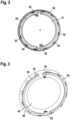
- Fig. 2
- eine Draufsicht auf die Trägerplatte des Kraftfahrzeugbeleuchtungsmoduls;
- Fig. 3
- eine Unteransicht des mit dem Stanzgitter verbundenen Lichtleiters des Kraftfahrzeugbeleuchtungsmoduls;
- Fig. 4
- eine perspektivische Ansicht eines Ausschnitts des mit dem Stanzgitter verbundenen Lichtleiters;
- Fig. 5
- eine schematische Schnittansicht des Oberteils des Kraftfahrzeugbeleuchtungsmoduls;
- In den Figuren sind identische Bauteile mit identischen Bezugszeichen versehen.
- Wie schematisch in
Fig. 1 gezeigt umfasst ein Kraftfahrzeugbeleuchtungsmodul 10 ein Gehäuse 20, das von einer Trägerplatte 21 und einem daran befestigten kreisrunden Oberteil 24 gebildet wird. Das Oberteil 24 ist teilweise lichtdurchlässig und schließt das Gehäuse 20 nach außen ab. - Die Trägerplatte 21 weist zwei mehrpolige Steckverbinder 22 auf, die jeweils dem direkten Anschluss eines Schaltkreises an einen Kabelsatz eines Kraftfahrzeugs dienen. Des Weiteren weist die Trägerplatte 21 eine Mehrzahl von Befestigungsvorrichtungen auf, die der Befestigung des Beleuchtungsmoduls 10 an einem Fahrzeugbauteil, beispielsweise an gut sichtbaren Stellen einer Fahrzeugfront und/oder eines Fahrzeughecks, dienen. Eine am Umfang der Trägerplatte 21 angeordnete Schräge 211 kann zur Realisierung einer Neigung des scheibenförmigen Lichtleiters in Bezug auf die Trägerplatte 21 verwendet werden. Eine beschichtete Textil-Membran 70 ist an der äußeren Seite der Trägerplatte 21 zur Abdichtung gegen den Eintritt von Feuchtigkeit in das Gehäuse 20 vorgesehen.
- Eine Mehrzahl von Lichtstrahlen 31 emittierenden Lichtquellen 30 ist in dem Gehäuse 20 aufgenommen. Jede der Lichtquellen 30 ist durch eine Leuchtdiode (LED) gebildet. Außerdem ist in dem Gehäuse 20 ein scheibenförmiger Lichtleiter 40 angeordnet. Die Lichtquellen 30 sind derart angeordnet, dass ein Ring ausgebildet ist, in dem der Lichtleiter 40 teilweise einliegt. Der Lichtleiter 40 weist an seinem Umfang einen Absatz 42 auf und überragt den durch die Lichtquellen 30 gebildeten Ring in radialer Richtung.
- Dadurch, dass der scheibenförmige Lichtleiter 40 an seinem Umfang einen Absatz 42 aufweist, ist der Lichtleiter 40 mit einem ersten Abschnitt 43, der einen ersten Durchmesser aufweist, und einem zweiten Abschnitt 44, der einen zweiten Durchmesser aufweist, der größer als der erste Durchmesser ist, ausgebildet, wie es insbesondere in
Fig. 4 erkennbar ist. Der erste Abschnitt 43 mit dem kleineren Durchmesser liegt in dem durch die Lichtquellen 30 gebildeten Ring ein und der zweite Abschnitt 44 mit dem größeren Durchmesser überragt den durch die Lichtquellen 30 gebildeten Ring in radialer Richtung. In dem durch die Lichtquellen 30 gebildeten Ring können zusätzlich weitere Elektronikkomponenten, wie beispielsweise ein Sensor für adaptive Geschwindigkeitsregelung (ACC-Sensor) und/oder eine Kamera 60 angeordnet sein. - Wie in den
Figuren 1 bis 4 gezeigt sind zumindest einige der Lichtstrahlen 31 der Lichtquellen 30 in Richtung auf den Mittelpunkt des in diesem Ausführungsbeispiel kreisförmigen Ringes gerichtet und in den Lichtleiter 40 eingeleitet, sodass der Lichtleiter 40 bis in den zweiten Abschnitt 44, der den durch die Lichtquellen 30 gebildeten Ring in radialer Richtung überragt, durch die auf dem Ring gegenüberliegend angeordneten Lichtquellen 30 beleuchtet ist. - Die Mehrzahl von Lichtquellen 30 ist ringförmig um den Lichtleiter 40 herum angeordnet, sodass sich jeweils zwei Lichtquellen 30 gegenüberliegen und sodass die von den Lichtquellen 30 emittierten Lichtstrahlen 31 seitlich in den Lichtleiter eintreten. Die von den Lichtquellen 30 emittierten Lichtstrahlen 31 breiten sich in dem Lichtleiter 40 von einer Einkoppelstelle eines Lichtstrahls 31 von der Lichtquelle 30 an dem Rand des ersten Abschnitts 43 zu dem gegenüberliegenden Rand des zweiten Abschnitts 44 aus und treten an dem Rand des zweiten Abschnitts 44 senkrecht in Richtung des Oberteils 24 aus dem Lichtleiter 40 aus, wie dies in
Fig. 1 dargestellt ist. - Wie aus
Fig. 1 und3 ersichtlich ist, ist jede der Lichtquellen 30 auf einer einzelnen Leiterplatte 32 angeordnet. Es können jedoch auch mehrere Lichtquellen 30 auf einer einzelnen Leiterplatte 32 angeordnet sein. Die einzelnen Leiterplatten 32 sind jeweils über ein von der Trägerplatte 21 getragenes ringförmiges Stanzgitter 34 elektrisch miteinander verbunden. - Wie in
Fig. 2 und 3 gezeigt, ist das Stanzgitter 34 zweigeteilt, um zwei voneinander getrennte Schaltkreise zu bilden. Die zwei getrennten Schaltkreise sind in der Einbauposition des Beleuchtungsmoduls 10 durch das zweigeteilte Stanzgitter eindeutig in einen rechten und einen linken Teil getrennt. Jedes Stanzgitter 34 weist einen Anschluss 35 auf, der einen direkten elektrischen Anschluss an einen Kabelsatz eines Kraftfahrzeugs über den in der Trägerplatte 21 integrierten mehrpoligen Steckverbinder 22 ermöglicht. - Wie in
Fig. 3 gezeigt ist eine Abdeckung 36 gegen direkten Lichtaustritt über den Lichtquellen 30 angeordnet, sodass die von den Lichtquellen 30 emittierten Lichtstrahlen 31 nicht zur Umgebung abgestrahlt werden, sondern ausschließlich seitlich in den scheibenförmigen Lichtleiter 40 eintreten. - Wie in
Fig. 4 gezeigt weist eine Leiterplatte 32 ein erstes Ende 321 und ein zweites Ende 322, das dem ersten Ende 321 gegenüber liegt, auf. An dem ersten Ende 321 ist eine Lichtquelle 30 angeordnet und dem zweiten Ende ist die Leiterplatte 32 mit dem Stanzgitter 34 elektrisch und mechanisch verbunden, wodurch ein Ring gebildet wird, dessen Durchmesser etwa dem des ersten Abschnitts 43 des Lichtleiter 40 entspricht. innerhalb des Ringes können weitere Elektronikkomponenten wie beispielsweise Sensoren angeordnet sein. - Wie in
Figur 1 erkennbar ist eine transparente Diffusorplatte 50 zwischen dem Lichtleiter 40 und dem Oberteil 24 angeordnet. Die Diffusorplatte 50 zerstreut die von den Lichtquellen 30 emittierten Lichtstrahlen 31. Die Diffusorplatte 50 weist dabei nicht gezeigte Strukturflächen auf. Die Strukturflächen sind an den Konturen des Emblems ausgerichtete Mikropyramiden. - Wie in
Fig. 5 gezeigt weist das Oberteil 24 eine äußere Oberfläche 25, die transparent poliert ist, und eine dreidimensional-strukturierte innere Oberfläche 26, die einem Emblem eines Kraftfahrzeugherstellers entspricht, auf. Die von den Lichtquellen 30 emittierten Lichtstrahlen 31 dienen der Beleuchtung des Emblems. Die innere Oberfläche 26 weist erste lichtundurchlässige Bereiche 27 mit einer dunklen Hochglanzoptik, zweite eingeschränkt lichtdurchlässige Bereiche 28, und dritte lichtdurchlässige Bereiche 29, die transparent poliert sind, auf. Die äußere Oberfläche 25 bildet eine Frontfläche des Oberteils 24, auf der das hinterleuchtete Emblem sichtbar ist. Durch die dreidimensional strukturierte innere Oberfläche 26 des Oberteils wird eine attraktive optische Darstellung des Emblems ermöglicht. Die dunkle Hochglanzoptik der ersten lichtundurchlässigen Bereiche 27 kann beispielsweise durch Lackieren, Bedampfen, usw. hergestellt werden. Die zweiten eingeschränkt lichtdurchlässigen Bereiche 28 bieten ein homogenes Lichtbild und können durch Vernarben, Satinieren, Bedampfen, Lackieren, usw. hergestellt werden, sodass von außen betrachtet, eine wertige Anmutung realisiert wird. Die dritten lichtdurchlässigen Bereiche 29 gewährleisten einen ungehinderten Lichtaustritt. - Das Beleuchtungsmodul 10 ist als eine Hochvolt-Komponente für den Einsatz in Hybrid-/Elektro-Kraftfahrzeugen und anderen Kraftfahrzeugen mit Hochvolt-Systemen ausgebildet.
-
- 10
- Kraftfahrzeugbeleuchtungsmodul
- 20
- Gehäuse
- 21
- Trägerplatte
- 211
- Schräge
- 22
- Steckverbinder
- 23
- Befestigungsvorrichtung
- 24
- Oberteil
- 25
- äußere Oberfläche
- 26
- innere Oberfläche
- 27
- erste lichtundurchlässige Bereiche
- 28
- zweite eingeschränkt lichtdurchlässige Bereiche
- 29
- dritte lichtdurchlässige Bereiche
- 30
- Lichtquelle
- 31
- Lichtstrahl
- 32
- Leiterplatte
- 321
- erstes Ende
- 322
- zweites Ende
- 34
- Stanzgitter
- 35
- Anschluss
- 36
- Abdeckung
- 40
- Lichtleiter
- 42
- Absatz
- 43
- erster Abschnitt
- 44
- zweiter Abschnitt
- 50
- Diffusorplatte
- 60
- Sensor für adaptive Geschwindigkeitsregelung
- 70
- Textil-Membran
Claims (10)
- Kraftfahrzeugbeleuchtungsmodul (10), zumindest umfassend ein Gehäuse (20), das von einer Trägerplatte (21) und einem daran befestigten kreisrunden oder elliptischen Oberteil (24) gebildet wird, wobei das Oberteil (24) zumindest teilweise lichtdurchlässig ist und das Gehäuse (20) nach außen abschließt, wobei eine Mehrzahl von Lichtstrahlen emittierenden Lichtquellen (30) in dem Gehäuse (20) aufgenommen sind, wobei in dem Gehäuse (20) ein scheibenförmiger Lichtleiter (40) angeordnet ist und die Lichtquellen (30) derart angeordnet sind, dass ein kreisrunder oder elliptischer Ring ausgebildet ist, wobei der Lichtleiter (40) in dem Ring zumindest teilweise einliegt, wobei der Lichtleiter (40) an seinem Umfang zumindest einen Absatz (42) aufweist und den durch die Lichtquellen (30) gebildeten Ring in radialer Richtung überragt, wobei der Lichtleiter mit einem ersten Abschnitt, der einen ersten Durchmesser aufweist, und einem zweiten Abschnitt, der einen zweiten Durchmesser aufweist, der größer als der erste Durchmesser ist, ausgebildet ist und wobei der erste Abschnitt mit dem kleineren Durchmesser in dem durch die Lichtquellen gebildeten Ring einliegt und der zweite Abschnitt mit dem größeren Durchmesser den durch die Lichtquellen gebildeten Ring in radialer Richtung überragt, dadurch gekennzeichnet, dass der Ring zweigeteilt ist, wobei zwei getrennte Abschnitte des Rings in der Einbauposition des Beleuchtungsmoduls durch eine senkrechte Trennlinie in einen rechten und einen linken Teil getrennt sind.
- Beleuchtungsmodul nach Anspruch 1, dadurch gekennzeichnet, dass zumindest ein Teil der Lichtstrahlen (31) der Lichtquellen (30) in Richtung auf den Mittelpunkt oder die Brennpunkte des Ringes gerichtet sind und in den Lichtleiter (40) eingeleitet sind, sodass der Lichtleiter (40) bis in jenen Teil, der den durch die Lichtquellen (30) gebildeten Ring in radialer Richtung überragt, durch die auf dem Ring gegenüberliegend angeordneten Lichtquellen (30) beleuchtet ist.
- Beleuchtungsmodul nach einem der vorherigen Ansprüche, dadurch gekennzeichnet, dass jede der Lichtquellen (30) auf einer einzelnen Leiterplatte (32) angeordnet ist oder mehrere Lichtquellen (30) auf einzelnen Leiterplatte (32) angeordnet sind und die einzelnen Leiterplatten (32) über ein von der Trägerplatte (21) getragenes ringförmiges Stanzgitter (34) elektrisch miteinander verbunden sind.
- Beleuchtungsmodul nach Anspruch 3, dadurch gekennzeichnet, dass das Stanzgitter (34) zweigeteilt ist, um zwei voneinander getrennte Schaltkreise zu bilden, insbesondere dass die zwei getrennten Schaltkreise in der Einbauposition des Beleuchtungsmoduls (10) durch eine senkrechte Trennlinie in einen rechten und einen linken Teil getrennt sind.
- Beleuchtungsmodul nach einem der vorherigen Ansprüche, dadurch gekennzeichnet, dass eine oder mehrere Abdeckung/en (36) gegen direkten Lichtaustritt über den Lichtquellen (30) angeordnet ist/sind, sodass das von den Lichtquellen (30) emittierte Lichtstrahlen (31) nicht zur Umgebung abgestrahlt werden, sondern seitlich in den scheibenförmigen Lichtleiter (40) eintreten.
- Beleuchtungsmodul nach einem der vorherigen Ansprüche, dadurch gekennzeichnet, dass das Oberteil (24) eine äußere Oberfläche (25), die insbesondere transparent poliert ist, und eine dreidimensional strukturierte innere Oberfläche (26), die einem Emblem entspricht, aufweist, wobei die innere Oberfläche (26) insbesondere erste lichtundurchlässige Bereiche (27), insbesondere mit einer dunklen Hochglanzoptik, zweite eingeschränkt lichtdurchlässige Bereiche (28) und dritte lichtdurchlässige insbesondere transparent polierte Bereiche (29) aufweist.
- Beleuchtungsmodul nach Anspruch 6, dadurch gekennzeichnet, dass eine transparente Diffusorplatte (50) zwischen dem Lichtleiter (40) und dem Oberteil (24) angeordnet ist, die die von den Lichtquellen (30) emittierten Lichtstrahlen (31) zerstreut, wobei die Diffusorplatte (50) Strukturflächen, insbesondere an den Konturen des Emblems ausgerichtete Mikropyramiden, aufweist.
- Beleuchtungsmodul nach einem der vorherigen Ansprüche, dadurch gekennzeichnet, dass jede der Lichtquellen (30) durch eine Leuchtdiode gebildet ist.
- Beleuchtungsmodul nach einem der vorherigen Ansprüche, dadurch gekennzeichnet, dass innerhalb des durch die Lichtquellen (30) gebildeten Rings und/oder in einem Einbauraum ausgehend vom Oberteil hinter der durch den Ring aufgespannten Ebene ein Sensor insbesondere für eine adaptive Geschwindigkeitsregelung (60) und/oder eine Kamera angeordnet ist/sind.
- Beleuchtungsmodul nach einem der vorherigen Ansprüche, dadurch gekennzeichnet, dass das Beleuchtungsmodul (10) als eine Hochvolt-Komponente ausgebildet ist.
Applications Claiming Priority (2)
| Application Number | Priority Date | Filing Date | Title |
|---|---|---|---|
| DE102018003553.1A DE102018003553A1 (de) | 2018-05-03 | 2018-05-03 | Kraftfahrzeugbeleuchtungsmodul |
| PCT/EP2019/000092 WO2019210990A1 (de) | 2018-05-03 | 2019-03-25 | Kraftfahrzeugbeleuchtungsmodul |
Publications (2)
| Publication Number | Publication Date |
|---|---|
| EP3788298A1 EP3788298A1 (de) | 2021-03-10 |
| EP3788298B1 true EP3788298B1 (de) | 2025-04-30 |
Family
ID=66290370
Family Applications (1)
| Application Number | Title | Priority Date | Filing Date |
|---|---|---|---|
| EP19719764.3A Active EP3788298B1 (de) | 2018-05-03 | 2019-03-25 | Kraftfahrzeugbeleuchtungsmodul |
Country Status (5)
| Country | Link |
|---|---|
| US (1) | US20210054983A1 (de) |
| EP (1) | EP3788298B1 (de) |
| CN (1) | CN112074688A (de) |
| DE (1) | DE102018003553A1 (de) |
| WO (1) | WO2019210990A1 (de) |
Families Citing this family (4)
| Publication number | Priority date | Publication date | Assignee | Title |
|---|---|---|---|---|
| DE102021127904A1 (de) | 2021-10-27 | 2023-04-27 | Bayerische Motoren Werke Aktiengesellschaft | Kraftfahrzeugbeleuchtungsmodul |
| US11371688B1 (en) * | 2021-11-16 | 2022-06-28 | Putco, Inc. | Automobile accessory light fixture mitigating RF emissions |
| CN117818499B (zh) * | 2024-03-05 | 2024-05-24 | 宁波鑫星汽车部件有限公司 | 一种发光均匀的汽车标牌 |
| JP2026059352A (ja) * | 2024-09-26 | 2026-04-07 | 豊田合成株式会社 | 発光エンブレム |
Citations (2)
| Publication number | Priority date | Publication date | Assignee | Title |
|---|---|---|---|---|
| US20160161080A1 (en) * | 2013-07-22 | 2016-06-09 | Renault S.A.S. | Lighting system, in particular for a motor vehicle lighting member, comprising integrated leds |
| WO2017009260A1 (en) * | 2015-07-10 | 2017-01-19 | SMR Patents S.à.r.l. | A light assembly and a vehicle design element including such a light assembly |
Family Cites Families (13)
| Publication number | Priority date | Publication date | Assignee | Title |
|---|---|---|---|---|
| JP2002093270A (ja) * | 2000-09-19 | 2002-03-29 | Nec Corp | 照光部構造 |
| KR100542058B1 (ko) * | 2002-12-06 | 2006-01-11 | 주식회사 에스엘 엘씨디 | 차량용 램프 |
| EP1666933A1 (de) * | 2004-12-02 | 2006-06-07 | Asulab S.A. | Optische Vorrichtung mit Doppelbeleuchtungsfunktion und bildliche Formung |
| EP1666992A1 (de) * | 2004-12-02 | 2006-06-07 | Asulab S.A. | Uhr mit einer leuchtenden Dekoration |
| ES2264382B1 (es) * | 2005-06-02 | 2008-02-01 | Grupo Antolin-Ingenieria, S.A. | Luminaria para techos de vehiculos. |
| US7307391B2 (en) * | 2006-02-09 | 2007-12-11 | Led Smart Inc. | LED lighting system |
| DE102007010328A1 (de) * | 2006-10-12 | 2008-04-17 | Trw Automotive Safety Systems Gmbh | Baugruppe zur beleuchteten Darstellung eines Logos |
| JP3169564U (ja) * | 2011-05-25 | 2011-08-04 | 株式会社ジュナック | Led発光エンブレム及びその製造方法 |
| JP2013103701A (ja) * | 2011-11-17 | 2013-05-30 | Ichikoh Ind Ltd | 車両用エンブレム |
| DE102013007856A1 (de) * | 2013-05-08 | 2014-11-13 | Audi Ag | Lichtleitkörper und Leuchtvorrichtung mit dem Lichtleitkörper |
| WO2015072133A1 (ja) * | 2013-11-15 | 2015-05-21 | パナソニックIpマネジメント株式会社 | ランプユニット |
| JP6607146B2 (ja) * | 2016-06-13 | 2019-11-20 | 豊田合成株式会社 | 発光エンブレム |
| DE202017105259U1 (de) * | 2017-08-31 | 2017-09-08 | Jute Industrial Co., Ltd. | Kombinationslampe |
-
2018
- 2018-05-03 DE DE102018003553.1A patent/DE102018003553A1/de active Pending
-
2019
- 2019-03-25 US US17/051,828 patent/US20210054983A1/en not_active Abandoned
- 2019-03-25 WO PCT/EP2019/000092 patent/WO2019210990A1/de not_active Ceased
- 2019-03-25 EP EP19719764.3A patent/EP3788298B1/de active Active
- 2019-03-25 CN CN201980030080.6A patent/CN112074688A/zh active Pending
Patent Citations (2)
| Publication number | Priority date | Publication date | Assignee | Title |
|---|---|---|---|---|
| US20160161080A1 (en) * | 2013-07-22 | 2016-06-09 | Renault S.A.S. | Lighting system, in particular for a motor vehicle lighting member, comprising integrated leds |
| WO2017009260A1 (en) * | 2015-07-10 | 2017-01-19 | SMR Patents S.à.r.l. | A light assembly and a vehicle design element including such a light assembly |
Also Published As
| Publication number | Publication date |
|---|---|
| US20210054983A1 (en) | 2021-02-25 |
| DE102018003553A1 (de) | 2019-11-07 |
| WO2019210990A1 (de) | 2019-11-07 |
| CN112074688A (zh) | 2020-12-11 |
| EP3788298A1 (de) | 2021-03-10 |
Similar Documents
| Publication | Publication Date | Title |
|---|---|---|
| EP3788298B1 (de) | Kraftfahrzeugbeleuchtungsmodul | |
| EP3538812B1 (de) | Beleuchtungsvorrichtung, insbesondere für ein kraftfahrzeug | |
| DE102016119326A1 (de) | Beleuchtungsvorrichtung für ein Fahrzeug | |
| DE102014116269B4 (de) | Rückleuchte für ein Fahrzeug | |
| DE112011101860B4 (de) | Außenspiegel-Anordnung mit einem Gehäuse umfassend eine Schaltkreisplatine mit einer Mehrzahl an lichtemittierenden Dioden | |
| WO2020043532A1 (de) | Beleuchtungsvorrichtung für ein kraftfahrzeug | |
| DE102017217507A1 (de) | Beleuchtbares Emblem | |
| DE102016121047A1 (de) | Beleuchtungseinrichtung für ein fahrzeug sowie herstellungsverfahren für eine beleuchtungseinrichtung | |
| DE102010032946A1 (de) | Kraftfahrzeug mit einem Innenraum, in dem eine Beleuchtungseinrichtung angeordnet ist | |
| DE102012103802B4 (de) | Schaltstufenindikator für ein fahrzeug | |
| EP2651695A1 (de) | Vorrichtung zur innenbeleuchtung in einem kraftfahrzeug | |
| DE102023122482A1 (de) | Beleuchtungseinrichtung, insbesondere für ein Kraftfahrzeug | |
| EP3962781A1 (de) | Beleuchtbares zierteil | |
| DE102022126896A1 (de) | Beleuchtungsvorrichtung für ein Kraftfahrzeug | |
| WO2015154939A1 (de) | Vorrichtung zur anzeige eines symbols und verfahren zum herstellen einer vorrichtung zur anzeige eines symbols | |
| DE102018118478B4 (de) | Verfahren zur Herstellung einer beleuchtbaren Baugruppe und beleuchtbare Baugruppe | |
| DE102023107763A1 (de) | Lichtmodul zur Hinterleuchtung eines Frontpanels oder eines Frontgrills eines Kraftfahrzeugs und Frontpanelbaugruppe eines Kraftfahrzeugs, umfassend ein Frontpanel und ein solches Lichtmodul | |
| DE102023107551A1 (de) | Beleuchtungsvorrichtung zum Aus- oder Hinterleuchten einer Lichtsignatur und Leuchteinheit mit einer aus- oder hinterleuchtbaren Lichtsignatur und einer solchen Beleuchtungsvorrichtung | |
| DE112019001649T5 (de) | Elektrische vorrichtung für ein fahrzeugtrittbrett | |
| WO2023072555A1 (de) | Kraftfahrzeugbeleuchtungsmodul | |
| DE102014010310B3 (de) | Beleuchtetes Zeigerinstrument für ein Kraftfahrzeug | |
| DE102008004483A1 (de) | Flexible Leuchtmittelbaugruppe für Fahrzeugleuchten | |
| DE10108073B4 (de) | Leuchtvorrichtung | |
| EP3954581A1 (de) | Beleuchtungseinrichtung für fahrzeuge | |
| DE202020100814U1 (de) | Leuchte für den Einsatz in einem Aussenspiegel eines Kraftfahrzeugs sowie Fahrzeugaussenspiegel mit derselben |
Legal Events
| Date | Code | Title | Description |
|---|---|---|---|
| STAA | Information on the status of an ep patent application or granted ep patent |
Free format text: STATUS: UNKNOWN |
|
| STAA | Information on the status of an ep patent application or granted ep patent |
Free format text: STATUS: THE INTERNATIONAL PUBLICATION HAS BEEN MADE |
|
| PUAI | Public reference made under article 153(3) epc to a published international application that has entered the european phase |
Free format text: ORIGINAL CODE: 0009012 |
|
| STAA | Information on the status of an ep patent application or granted ep patent |
Free format text: STATUS: REQUEST FOR EXAMINATION WAS MADE |
|
| 17P | Request for examination filed |
Effective date: 20201123 |
|
| AK | Designated contracting states |
Kind code of ref document: A1 Designated state(s): AL AT BE BG CH CY CZ DE DK EE ES FI FR GB GR HR HU IE IS IT LI LT LU LV MC MK MT NL NO PL PT RO RS SE SI SK SM TR |
|
| AX | Request for extension of the european patent |
Extension state: BA ME |
|
| DAV | Request for validation of the european patent (deleted) | ||
| DAX | Request for extension of the european patent (deleted) | ||
| STAA | Information on the status of an ep patent application or granted ep patent |
Free format text: STATUS: EXAMINATION IS IN PROGRESS |
|
| 17Q | First examination report despatched |
Effective date: 20220926 |
|
| P01 | Opt-out of the competence of the unified patent court (upc) registered |
Effective date: 20230502 |
|
| GRAP | Despatch of communication of intention to grant a patent |
Free format text: ORIGINAL CODE: EPIDOSNIGR1 |
|
| STAA | Information on the status of an ep patent application or granted ep patent |
Free format text: STATUS: GRANT OF PATENT IS INTENDED |
|
| INTG | Intention to grant announced |
Effective date: 20241217 |
|
| GRAS | Grant fee paid |
Free format text: ORIGINAL CODE: EPIDOSNIGR3 |
|
| GRAA | (expected) grant |
Free format text: ORIGINAL CODE: 0009210 |
|
| STAA | Information on the status of an ep patent application or granted ep patent |
Free format text: STATUS: THE PATENT HAS BEEN GRANTED |
|
| AK | Designated contracting states |
Kind code of ref document: B1 Designated state(s): AL AT BE BG CH CY CZ DE DK EE ES FI FR GB GR HR HU IE IS IT LI LT LU LV MC MK MT NL NO PL PT RO RS SE SI SK SM TR |
|
| REG | Reference to a national code |
Ref country code: CH Ref legal event code: EP Ref country code: GB Ref legal event code: FG4D Free format text: NOT ENGLISH |
|
| REG | Reference to a national code |
Ref country code: DE Ref legal event code: R096 Ref document number: 502019013288 Country of ref document: DE |
|
| REG | Reference to a national code |
Ref country code: IE Ref legal event code: FG4D Free format text: LANGUAGE OF EP DOCUMENT: GERMAN |
|
| REG | Reference to a national code |
Ref country code: NL Ref legal event code: MP Effective date: 20250430 |
|
| PG25 | Lapsed in a contracting state [announced via postgrant information from national office to epo] |
Ref country code: PT Free format text: LAPSE BECAUSE OF FAILURE TO SUBMIT A TRANSLATION OF THE DESCRIPTION OR TO PAY THE FEE WITHIN THE PRESCRIBED TIME-LIMIT Effective date: 20250901 Ref country code: FI Free format text: LAPSE BECAUSE OF FAILURE TO SUBMIT A TRANSLATION OF THE DESCRIPTION OR TO PAY THE FEE WITHIN THE PRESCRIBED TIME-LIMIT Effective date: 20250430 Ref country code: ES Free format text: LAPSE BECAUSE OF FAILURE TO SUBMIT A TRANSLATION OF THE DESCRIPTION OR TO PAY THE FEE WITHIN THE PRESCRIBED TIME-LIMIT Effective date: 20250430 |
|
| REG | Reference to a national code |
Ref country code: LT Ref legal event code: MG9D |
|
| PG25 | Lapsed in a contracting state [announced via postgrant information from national office to epo] |
Ref country code: GR Free format text: LAPSE BECAUSE OF FAILURE TO SUBMIT A TRANSLATION OF THE DESCRIPTION OR TO PAY THE FEE WITHIN THE PRESCRIBED TIME-LIMIT Effective date: 20250731 Ref country code: NO Free format text: LAPSE BECAUSE OF FAILURE TO SUBMIT A TRANSLATION OF THE DESCRIPTION OR TO PAY THE FEE WITHIN THE PRESCRIBED TIME-LIMIT Effective date: 20250730 |
|
| PG25 | Lapsed in a contracting state [announced via postgrant information from national office to epo] |
Ref country code: NL Free format text: LAPSE BECAUSE OF FAILURE TO SUBMIT A TRANSLATION OF THE DESCRIPTION OR TO PAY THE FEE WITHIN THE PRESCRIBED TIME-LIMIT Effective date: 20250430 Ref country code: PL Free format text: LAPSE BECAUSE OF FAILURE TO SUBMIT A TRANSLATION OF THE DESCRIPTION OR TO PAY THE FEE WITHIN THE PRESCRIBED TIME-LIMIT Effective date: 20250430 |
|
| PG25 | Lapsed in a contracting state [announced via postgrant information from national office to epo] |
Ref country code: BG Free format text: LAPSE BECAUSE OF FAILURE TO SUBMIT A TRANSLATION OF THE DESCRIPTION OR TO PAY THE FEE WITHIN THE PRESCRIBED TIME-LIMIT Effective date: 20250430 |
|
| PG25 | Lapsed in a contracting state [announced via postgrant information from national office to epo] |
Ref country code: HR Free format text: LAPSE BECAUSE OF FAILURE TO SUBMIT A TRANSLATION OF THE DESCRIPTION OR TO PAY THE FEE WITHIN THE PRESCRIBED TIME-LIMIT Effective date: 20250430 |
|
| PG25 | Lapsed in a contracting state [announced via postgrant information from national office to epo] |
Ref country code: RS Free format text: LAPSE BECAUSE OF FAILURE TO SUBMIT A TRANSLATION OF THE DESCRIPTION OR TO PAY THE FEE WITHIN THE PRESCRIBED TIME-LIMIT Effective date: 20250731 |
|
| PG25 | Lapsed in a contracting state [announced via postgrant information from national office to epo] |
Ref country code: IS Free format text: LAPSE BECAUSE OF FAILURE TO SUBMIT A TRANSLATION OF THE DESCRIPTION OR TO PAY THE FEE WITHIN THE PRESCRIBED TIME-LIMIT Effective date: 20250830 |
|
| PG25 | Lapsed in a contracting state [announced via postgrant information from national office to epo] |
Ref country code: LV Free format text: LAPSE BECAUSE OF FAILURE TO SUBMIT A TRANSLATION OF THE DESCRIPTION OR TO PAY THE FEE WITHIN THE PRESCRIBED TIME-LIMIT Effective date: 20250430 |
|
| PG25 | Lapsed in a contracting state [announced via postgrant information from national office to epo] |
Ref country code: DK Free format text: LAPSE BECAUSE OF FAILURE TO SUBMIT A TRANSLATION OF THE DESCRIPTION OR TO PAY THE FEE WITHIN THE PRESCRIBED TIME-LIMIT Effective date: 20250430 Ref country code: SM Free format text: LAPSE BECAUSE OF FAILURE TO SUBMIT A TRANSLATION OF THE DESCRIPTION OR TO PAY THE FEE WITHIN THE PRESCRIBED TIME-LIMIT Effective date: 20250430 |
|
| PG25 | Lapsed in a contracting state [announced via postgrant information from national office to epo] |
Ref country code: CZ Free format text: LAPSE BECAUSE OF FAILURE TO SUBMIT A TRANSLATION OF THE DESCRIPTION OR TO PAY THE FEE WITHIN THE PRESCRIBED TIME-LIMIT Effective date: 20250430 |
|
| PG25 | Lapsed in a contracting state [announced via postgrant information from national office to epo] |
Ref country code: EE Free format text: LAPSE BECAUSE OF FAILURE TO SUBMIT A TRANSLATION OF THE DESCRIPTION OR TO PAY THE FEE WITHIN THE PRESCRIBED TIME-LIMIT Effective date: 20250430 |
|
| PG25 | Lapsed in a contracting state [announced via postgrant information from national office to epo] |
Ref country code: RO Free format text: LAPSE BECAUSE OF FAILURE TO SUBMIT A TRANSLATION OF THE DESCRIPTION OR TO PAY THE FEE WITHIN THE PRESCRIBED TIME-LIMIT Effective date: 20250430 Ref country code: SK Free format text: LAPSE BECAUSE OF FAILURE TO SUBMIT A TRANSLATION OF THE DESCRIPTION OR TO PAY THE FEE WITHIN THE PRESCRIBED TIME-LIMIT Effective date: 20250430 |
|
| PG25 | Lapsed in a contracting state [announced via postgrant information from national office to epo] |
Ref country code: IT Free format text: LAPSE BECAUSE OF FAILURE TO SUBMIT A TRANSLATION OF THE DESCRIPTION OR TO PAY THE FEE WITHIN THE PRESCRIBED TIME-LIMIT Effective date: 20250430 |
|
| REG | Reference to a national code |
Ref country code: DE Ref legal event code: R097 Ref document number: 502019013288 Country of ref document: DE |
|
| PLBE | No opposition filed within time limit |
Free format text: ORIGINAL CODE: 0009261 |
|
| STAA | Information on the status of an ep patent application or granted ep patent |
Free format text: STATUS: NO OPPOSITION FILED WITHIN TIME LIMIT |
|
| REG | Reference to a national code |
Ref country code: CH Ref legal event code: L10 Free format text: ST27 STATUS EVENT CODE: U-0-0-L10-L00 (AS PROVIDED BY THE NATIONAL OFFICE) Effective date: 20260311 |
|
| 26N | No opposition filed |
Effective date: 20260202 |
|
| PGFP | Annual fee paid to national office [announced via postgrant information from national office to epo] |
Ref country code: DE Payment date: 20260331 Year of fee payment: 8 |