EP3787993B1 - Erfassungsvorrichtung für einen kran - Google Patents
Erfassungsvorrichtung für einen kran Download PDFInfo
- Publication number
- EP3787993B1 EP3787993B1 EP19795768.1A EP19795768A EP3787993B1 EP 3787993 B1 EP3787993 B1 EP 3787993B1 EP 19795768 A EP19795768 A EP 19795768A EP 3787993 B1 EP3787993 B1 EP 3787993B1
- Authority
- EP
- European Patent Office
- Prior art keywords
- hook
- sensing device
- crane
- deviation
- measurement unit
- Prior art date
- Legal status (The legal status is an assumption and is not a legal conclusion. Google has not performed a legal analysis and makes no representation as to the accuracy of the status listed.)
- Active
Links
Images


Classifications
-
- B—PERFORMING OPERATIONS; TRANSPORTING
- B66—HOISTING; LIFTING; HAULING
- B66C—CRANES; LOAD-ENGAGING ELEMENTS OR DEVICES FOR CRANES, CAPSTANS, WINCHES, OR TACKLES
- B66C1/00—Load-engaging elements or devices attached to lifting or lowering gear of cranes or adapted for connection therewith for transmitting lifting forces to articles or groups of articles
- B66C1/10—Load-engaging elements or devices attached to lifting or lowering gear of cranes or adapted for connection therewith for transmitting lifting forces to articles or groups of articles by mechanical means
- B66C1/22—Rigid members, e.g. L-shaped members, with parts engaging the under surface of the loads; Crane hooks
- B66C1/34—Crane hooks
- B66C1/40—Crane hooks formed or fitted with load measuring or indicating devices
-
- B—PERFORMING OPERATIONS; TRANSPORTING
- B66—HOISTING; LIFTING; HAULING
- B66C—CRANES; LOAD-ENGAGING ELEMENTS OR DEVICES FOR CRANES, CAPSTANS, WINCHES, OR TACKLES
- B66C13/00—Other constructional features or details
- B66C13/18—Control systems or devices
- B66C13/46—Position indicators for suspended loads or for crane elements
-
- B—PERFORMING OPERATIONS; TRANSPORTING
- B66—HOISTING; LIFTING; HAULING
- B66C—CRANES; LOAD-ENGAGING ELEMENTS OR DEVICES FOR CRANES, CAPSTANS, WINCHES, OR TACKLES
- B66C15/00—Safety gear
- B66C15/06—Arrangements or use of warning devices
- B66C15/065—Arrangements or use of warning devices electrical
-
- B—PERFORMING OPERATIONS; TRANSPORTING
- B66—HOISTING; LIFTING; HAULING
- B66C—CRANES; LOAD-ENGAGING ELEMENTS OR DEVICES FOR CRANES, CAPSTANS, WINCHES, OR TACKLES
- B66C23/00—Cranes comprising essentially a beam, boom, or triangular structure acting as a cantilever and mounted for translatory of swinging movements in vertical or horizontal planes or a combination of such movements, e.g. jib-cranes, derricks, tower cranes
- B66C23/88—Safety gear
- B66C23/90—Devices for indicating or limiting lifting moment
- B66C23/905—Devices for indicating or limiting lifting moment electrical
-
- B—PERFORMING OPERATIONS; TRANSPORTING
- B66—HOISTING; LIFTING; HAULING
- B66C—CRANES; LOAD-ENGAGING ELEMENTS OR DEVICES FOR CRANES, CAPSTANS, WINCHES, OR TACKLES
- B66C23/00—Cranes comprising essentially a beam, boom, or triangular structure acting as a cantilever and mounted for translatory of swinging movements in vertical or horizontal planes or a combination of such movements, e.g. jib-cranes, derricks, tower cranes
- B66C23/18—Cranes comprising essentially a beam, boom, or triangular structure acting as a cantilever and mounted for translatory of swinging movements in vertical or horizontal planes or a combination of such movements, e.g. jib-cranes, derricks, tower cranes specially adapted for use in particular purposes
- B66C23/36—Cranes comprising essentially a beam, boom, or triangular structure acting as a cantilever and mounted for translatory of swinging movements in vertical or horizontal planes or a combination of such movements, e.g. jib-cranes, derricks, tower cranes specially adapted for use in particular purposes mounted on road or rail vehicles; Manually-movable jib-cranes for use in workshops; Floating cranes
- B66C23/38—Cranes comprising essentially a beam, boom, or triangular structure acting as a cantilever and mounted for translatory of swinging movements in vertical or horizontal planes or a combination of such movements, e.g. jib-cranes, derricks, tower cranes specially adapted for use in particular purposes mounted on road or rail vehicles; Manually-movable jib-cranes for use in workshops; Floating cranes with separate prime movers for crane and vehicle
-
- B—PERFORMING OPERATIONS; TRANSPORTING
- B66—HOISTING; LIFTING; HAULING
- B66C—CRANES; LOAD-ENGAGING ELEMENTS OR DEVICES FOR CRANES, CAPSTANS, WINCHES, OR TACKLES
- B66C23/00—Cranes comprising essentially a beam, boom, or triangular structure acting as a cantilever and mounted for translatory of swinging movements in vertical or horizontal planes or a combination of such movements, e.g. jib-cranes, derricks, tower cranes
- B66C23/62—Constructional features or details
- B66C23/64—Jibs
- B66C23/70—Jibs constructed of sections adapted to be assembled to form jibs or various lengths
- B66C23/701—Jibs constructed of sections adapted to be assembled to form jibs or various lengths telescopic
-
- B—PERFORMING OPERATIONS; TRANSPORTING
- B66—HOISTING; LIFTING; HAULING
- B66C—CRANES; LOAD-ENGAGING ELEMENTS OR DEVICES FOR CRANES, CAPSTANS, WINCHES, OR TACKLES
- B66C23/00—Cranes comprising essentially a beam, boom, or triangular structure acting as a cantilever and mounted for translatory of swinging movements in vertical or horizontal planes or a combination of such movements, e.g. jib-cranes, derricks, tower cranes
- B66C23/62—Constructional features or details
- B66C23/82—Luffing gear
- B66C23/821—Bracing equipment for booms
- B66C23/826—Bracing equipment acting at an inclined angle to vertical and horizontal directions
- B66C23/828—Bracing equipment acting at an inclined angle to vertical and horizontal directions where the angle is adjustable
-
- B—PERFORMING OPERATIONS; TRANSPORTING
- B66—HOISTING; LIFTING; HAULING
- B66C—CRANES; LOAD-ENGAGING ELEMENTS OR DEVICES FOR CRANES, CAPSTANS, WINCHES, OR TACKLES
- B66C2700/00—Cranes
- B66C2700/08—Electrical assemblies or electrical control devices for cranes, winches, capstans or electrical hoists
Definitions
- the invention relates to a sensing device and method for assisting crane riggers that is particularly useful for detecting unsafe, out of plumb conditions of a lifting hook of a luffing type crane.
- Warning devices to signal or to correct an unsafe lifting condition in the use of cranes are known.
- the difficulty of accurately identifying problems with the crane boom is increased when the boom is particularly long and/or elevated to a high angle and can be further complicated when a prevailing wind is present.
- the load to be lifted is out of view by a crane operator and the operator must rely solely upon instructions issued by a third party, such as a Rigger or Dogman.
- CN 102923572B discloses a luffing crane according to the preamble of claim 1. More in detail, it relates to crane load space swing angle detection technology and an apparatus thereof, wherein the apparatus comprises a measurement box and a signal receiving processor.
- a sensor in the measurement box arranged on a lifting hook/load measures a spatial attitude of the lifting hook/load relative to a geodetic coordinate
- the signal receiving processor arranged on a crane body/boom measures a spatial attitude of the crane body/boom relative to the geodetic coordinate based on the sensor
- a spatial attitude parameter of the crane load relative to the crane body/boom can be calculated through coordinate transformation
- the calculated parameter can be transmitted to a crane control box through a bus control unit to automatically control.
- a spatial swing condition of the crane load can be accurately measured so as to help the crane to achieve anti-swing control and improve safety production efficiency.
- the invention resides in a sensing device for a crane for detecting unsafe operating conditions comprising:
- the sensing device is adapted to activate an alert element if the deviation of the hook is within a predefined range.
- the sensing device is adapted to indicate a plumb or an out of plumb lift cable attached to a load.
- the inertial measurement unit comprises an electronic gyroscope adapted to measure orientation of the hook and obtain orientation data.
- the inertial measurement unit further comprises an accelerometer adapted to measure orientation of the hook and obtain orientation data.
- the gyroscope and the accelerometer are adapted to measure deviation from vertical pitch of the hook.
- the inertial measurement unit comprises a magnetometer adapted to measure changes of the hook relative to magnetic north.
- the magnetometer is adapted to measure yaw of the hook.
- the sensing device further comprises a microcontroller.
- the microcontroller is arranged to calculate a compensation factor for the magnetometer.
- the microcontroller is arranged to calculate the compensation factor to compensate for heavy iron present in the hook.
- the microcontroller is arranged to combine orientation data measured by the accelerometer and the gyroscope with a statistical estimation filter.
- the statistical estimation filter comprises a Kalman filter.
- the microcontroller is arranged to use the combination of the orientation data with the statistical estimation filter to determine deviation from the plumb position.
- the sensing device comprises a housing.
- the housing is waterproof.
- the inertial measurement unit is located within the housing.
- the sensing device is removably attached to a collar of the hook.
- the inertial measurement unit is adapted to measure the deviation of the hook in degrees.
- the sensing device is connected to a graphical display device.
- the sensing device is wirelessly connected to the graphical display device.
- the sensing device is arranged to operate the graphical display device to display a visual indication of the hook in relation to the plumb position on the graphical display device.
- the sensing device is connected to a crane sensor bus.
- the sensing device is arranged to read one or more of a load weight, a boom radius, a boom length and a total weight from the crane sensor bus.
- the alert element is in the form of an audible signal generator or a visual signal generator, such as a flashing light or a pop-up on a graphic display.
- the invention further resides in a method for detecting an unsafe operating lifting condition for a crane, the method comprising the steps of:
- the method comprises the further step of determining if the deviation of the hook from the plumb position is less than or greater than a predetermined limit.
- the step of determining a deviation of the hook comprises calculating an angle of pitch of the hook using the inertial measurement unit.
- the step of determining a deviation further comprises calculating the angle of yaw of the hook using the inertial measurement unit.
- the method comprises the further step of operating an alert element to indicate that the deviation of the hook is greater than the predetermined limit.
- the alert element indicates that the operating condition of the crane is unsafe.
- the method comprises the further step of determining if the hook is in a plumb or out of plumb position.
- the alert element comprises a display device of an operator of the crane and/or a rigger.
- the method further comprises the step of calculating yaw of the hook.
- yaw of the hook is calculated by a magnetometer.
- the magnetometer compensates for any twist in the cables attached to the hook.
- the alert element is received by a graphical display device.
- the alert element is transmitted to and received by the graphical display device wirelessly over a Low-Power Wide-Area Network (LPWAN) for long range communication.
- LPWAN Low-Power Wide-Area Network
- the invention resides in a system for determining deviation of a hook from a plumb position, the system comprising:
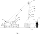
- the crane hook sensing device 100 calculates angles and deviations from inertial axes to determine the optimal rigging application of a load 130 engaged by hoist cables 122 of the crane 120.
- FIG. 3 there is illustrated a system 1 including the crane hook sensing device 100, the cabin processor assembly 131 and rigger display device 141.
- the crane hook sensing device 100 comprises a microcontroller board 101 which includes a microcontroller 103 that accesses a digital memory 105 that stores firmware 107 containing instructions to calculate the angle ⁇ 1 of deviation from a vertical axis (or plumb position) of the hook 110 relative to the boom head 124, as well as compensation for any twist of the hook 110. Twisting of the hook 110 typically occurs when a hook block is reeved with an odd number of falls of hoist rope or wind loading and affects the horizontal orientation (yaw) of the hook 110 which will affect the accuracy of calculations of existing systems.
- the plumb position is defined by a vertical line 140 (seen in FIG. 2 ) extending from the ground to the boom head 124.
- the microcontroller 103 also operates radio communications Tx/Rx unit 109 to establish radio communications with Tx/Rx unit 98 of between the crane cabin 126 and rigger display 141 using a long range radio technology, such as Low-Power Wide-Area Network (LPWAN) for example.
- LPWAN Low-Power Wide-Area Network
- the crane hook sensing device 100 includes an inertial measurement unit (IMU) 111 in communication with microcontroller 103.
- the IMU 111 measures the 3-axis orientation of the hook 110 (i.e. pitch, roll and yaw).
- the IMU 111 includes a gyroscopic sensor 112 (such as an electronic gyroscope) for providing long term orientation data and an accelerometer 113 for providing short term orientation data combined with a Kalman filter (or other suitable statistical estimation filter) to accurately determine the variation from the gravity vector.
- a magnetometer 114 of the IMU 111 measures the yaw changes of the hook 110 relative to magnetic north, with calculations in accordance with firmware 107 made to compensate for the heavy iron of the hook 110 which the sensing device 100 is mounted upon.
- the hook sensing device 100 is housed within a waterproof housing 121 having a mounting bracket which is removably affixed to the collar 123 of the hook 110 inside the cheekbones 125 of the hook block.
- the sensing device 100 can be removed from the hook 110 for recharging and maintenance, as required.
- the sensing device 100 is powered by a battery 102 located within the housing 121.
- the battery 102 is a rechargeable battery that can be recharged using a standard USB charging cable.
- a cabin processor assembly 131 Located in the cabin 126 of the crane 120 is a cabin processor assembly 131 connected to the crane sensor bus 133 and coupled to cabin radio Tx/Rx unit 98.
- the assembly 131 reads lift specific data streams from the existing crane sensors S1,...,Sn including the following: load weight, boom radius, boom length and total weight.
- a display 135 within the cabin 126 provides the operator 137 with a graphical view of the orientation of the hook in relation to the centre of the load 130 as a bird's eye view of the horizontal plane.
- the display 135 uses a microprocessor programmed with software to extract the crane data as well as draw the display. Hardware specific to the integration required to extract the crane data is used to connect the display 135 to the existing crane sensors S1,... Sn.
- the Rigger 139 also has a display assembly 141.
- the Rigger display assembly 141 includes a radio receiver 142 that receives the data stream sent by the radio Tx/Rx unit 109 of sensing device 100 which includes the real time calculation results that the Rigger 139 can use to adjust the load 130 for optimal lifting.
- the format of the display 141 can vary, from smart phones to smart glasses, or specifically designed display apparatus that is appropriate for onsite construction use.
- the Rigger display 141 provides a graphical plumb gauge that highlights the deviation in degrees (from +10° to -10°) from the vertical as well as other data from the crane sensors S1,... Sn like weight and other indications relevant to the Rigger 139.
- the radio Tx/Rx unit 109 comprises long range radios for bidirectional communication between the sensing device 100, the radio Tx/Rx unit 98 of the crane cabin 126 and the radio receiving unit 142 of the Rigger display apparatus 141.
- the radio Tx/Rx unit 109 has long range capability to ensure the signal is transferred successfully between the radio Tx/Rx unit 98, the sensing device 100 and the Rigger display apparatus 141 to cater for varying on-site conditions which can adversely affect signal conditions.
- the system uses a data transfer protocol that is specifically designed to ensure the correct information is received for the crane operator 137 and rigger display apparatus 141 and is resilient to errors in transmission.
- the sensing device 100 measures the deviation in degrees from vertical orientation (indicated by plumb line 140) of the hook 100 underneath the boom 124 which is referred to as "plumb" calibrated to suit by the Rigger 139 at the commencement of lifting.
- This information is sent via long range radio frequency to a radio Tx/Rx unit 98 in the crane operator's cabin 126 and to a radio Tx/Rx unit assembly 142 of rigger display 141 to display to rigger 139.
- the sensing device 100 is attached to the hook 110 of the crane 120.
- the hook 110 is then attached to the load 130 in preparation for lifting.
- the sensing device 100 calculates the angle of the pitch plane in real time based on a comparison of the gravity vector measured by the accelerometer of the IMU 111 and compensated by the angular momentum of the gyroscope of the IMU 111 using modified Kalman equations.
- the magnetometer of the IMU 111 preferably a compass
- the magnetometer of the IMU 111 is used to calculate and compensate for the twist, allowing for high accuracy when calculating the pitch angle for a large number of crane lifting situations.
- an alert or indication that the hook 110 is currently in an unsafe operating condition can be issued to the operator 137 in the crane cabin 126 by means of display 135 and/or the display device 141 of the Rigger 139 so that the lifting operation may be appropriately adjusted.
- a predetermined range i.e. not beyond the allowable deviation limit
- an alert or indication that the hook is currently in a safe operation condition can be issued to the operator 137 in the crane cabin 126 through alert generator 143 and/or the display device 141 of the Rigger 139.
- the alert generator 143 is under the control of cabin processor 131 for producing visual and/or audible signals as instructed by the sensing device 100.
- the alert for an unsafe condition can be in the form of a visual element, such as a red flashing light, or an audible signal, such as a siren.
- a visual element such as a red flashing light
- an audible signal such as a siren.
- the light may change to green, or another colour predetermined to signal a safe condition.
- the audible signal could be a bell chime or other predetermined sound which signifies the safe condition.
- FIG. 2 An example of the sensing device 100 in use is shown in FIG. 2 .
- the sensing device 100 located adjacent the hook 110 of the crane 120, is measuring the difference in degrees from the plumb position of the hook 110, illustrated by plumb line 140 and deviation line 150.
- an alert would be issued to the operator 137 in the cabin 126 of the crane 120 by means of display 135 and/or alert generator 143 and the display device 141 of rigger 139.
- the operator 137 and rigger 139 are immediately made aware of an unsafe condition and are able to readily correct the situation by manipulation of the crane controls to achieve a safe operation condition, which can also be detected and indicated by the sensing device.
- the sensing device can also be calibrated to allow for an "offset" plumb for situations where a portion of the load has been taken by the crane. This is particularly useful when rigging has different lengths and configurations of both sides of the load.
- the sensing device can effectively compute any lateral orientation changes in a hook or hookblock of a crane, such as a specific number of falls of hoist rope in crane configuration or specific rigging applications causing torque, or high winds.
- Another advantage lies in the ability to indicate both safe and unsafe operating conditions of a lifting operation.
- adjectives such as first and second, left and right, top and bottom, and the like may be used solely to distinguish one element or action from another element or action without necessarily requiring or implying any actual such relationship or order.
- reference to an integer or a component or step (or the like) is not to be interpreted as being limited to only one of that integer, component, or step, but rather could be one or more of that integer, component, or step, etc.
- the terms 'comprises', 'comprising', 'includes', 'including', or similar terms are intended to mean a non-exclusive inclusion, such that a method, system or apparatus that comprises a list of elements or steps does not include those elements solely, but may well include other elements not listed.
Landscapes
- Engineering & Computer Science (AREA)
- Mechanical Engineering (AREA)
- Automation & Control Theory (AREA)
- Jib Cranes (AREA)
Claims (15)
- Erfassungsvorrichtung (100) für einen Wippkran zum Detektieren von unsicheren Betriebsbedingungen, die Folgendes umfasst:
eine Trägheitsmesseinheit (111) zum Messen des Nickens und Gierens eines Hakens (110) eines Krans, der an einer Last (130) befestigt ist, wobei die Trägheitsmesseinheit (111) Folgendes umfasst:ein elektronisches Gyroskop;einen Beschleunigungsmesser (113), wobei das elektronische Gyroskop und der Beschleunigungsmesser (113) dazu ausgelegt sind, die Ausrichtung des Hakens (110) zu messen und Ausrichtungsdaten zu erhalten, um die Abweichung des Hakens (110) von einer lotrechten Position zu messen;ein Magnetometer (114), das dazu ausgelegt ist, das Gieren des Hakens (110) zu messen, und das dazu ausgelegt ist, Änderungen des Hakens (110) im Verhältnis zum magnetischen Norden zu messen und Gierdaten zu erhalten, undgekennzeichnet durch eine Mikrosteuerung (103), die für Folgendes angeordnet ist:Berechnen eines Kompensationsfaktors aus den von dem Magnetometer (114) gemessenen Gierdaten;Kombinieren der von dem elektronischen Gyroskop und dem Beschleunigungsmesser (113) gemessenen Ausrichtungsdaten mit einem statistischen Schätzungsfilter; undBestimmen der Abweichung des Hakens (110) des Krans von der lotrechten Position vor Beginn des Hebens der am Haken (110) befestigten Last (120) unter Verwendung der Kombination der Ausrichtungsdaten mit dem statistischen Schätzfilter und dem Kompensationsfaktor,wobei die Trägheitsmesseinheit (111) dazu ausgelegt ist, ein Alarmelement zu aktivieren, wenn die Abweichung des Hakens (110) einen vorgegebenen Grenzwert überschreitet. - Erfassungsvorrichtung (100) nach Anspruch 1, wobei die Erfassungsvorrichtung (100) dazu ausgelegt ist, ein Alarmelement zu aktivieren, wenn die Abweichung des Hakens (110) innerhalb eines vordefinierten Bereichs liegt, und das Alarmelement ein Generator für akustische Signale oder ein Generator für visuelle Signale ist.
- Erfassungsvorrichtung (100) nach Anspruch 1, wobei die Erfassungsvorrichtung (100) dazu ausgelegt ist, ein lotrechtes oder ein nicht lotrechtes Hebeseil anzuzeigen, das an einer Last (130) befestigt ist.
- Erfassungsvorrichtung (100) nach einem der vorhergehenden Ansprüche, wobei die Erfassungsvorrichtung (100) ein wasserfestes Gehäuse (121) umfasst und die Trägheitsmesseinheit (111) sich innerhalb des wasserfesten Gehäuses (121) befindet.
- Erfassungsvorrichtung (100) nach einem der vorhergehenden Ansprüche, wobei die Trägheitsmesseinheit (111) dazu ausgelegt ist, die Abweichung des Hakens (110) in Grad zu messen.
- Erfassungsvorrichtung (100) nach einem der vorhergehenden Ansprüche, wobei die Erfassungsvorrichtung (100) drahtlos mit einer grafischen Anzeigevorrichtung (141) verbunden ist, und die Erfassungsvorrichtung (100) so angeordnet ist, dass sie die grafische Anzeigevorrichtung (141) betätigt, um eine visuelle Anzeige des Hakens (110) in Bezug auf die lotrechte Position auf der grafischen Anzeigevorrichtung (141) anzuzeigen.
- Erfassungsvorrichtung (100) nach einem der vorhergehenden Ansprüche, wobei die Erfassungsvorrichtung (100) mit einem Sensorbus (133) des Krans verbunden ist und die Erfassungsvorrichtung (100) so angeordnet ist, dass sie eines oder mehrere von einem Lastgewicht, einem Auslegerradius, einer Auslegerlänge und einem Gesamtgewicht aus dem Sensorbus (133) des Krans liest.
- Verfahren zum Detektieren einer unsicheren Hebebetriebsbedingung für einen Wippkran (120) nach Anspruch 1, wobei das Verfahren die folgenden Schritte umfasst:Messen der Ausrichtung eines Hakens (110) eines Krans, der an einer Last (130) befestigt ist, mittels eines elektronischen Gyroskops und eines Beschleunigungsmessers (113) einer Trägheitsmesseinheit (111), die an dem Haken (110) des Krans befestigt ist;Erhalten von Ausrichtungsdaten von dem elektronischen Gyroskop und dem Beschleunigungsmesser (113) der Trägheitsmesseinheit (111);Messen des Gierens des Hakens (110) mittels eines Magnetometers (114) der Trägheitsmesseinheit (111);Erhalten von Gierdaten von dem Magnetometer (114) der Trägheitsmesseinheit (111);wobei das Verfahren gekennzeichnet ist durch das Berechnen eines Kompensationsfaktors aus den von dem Magnetometer (114) gemessenen Gierdaten unter Verwendung der Mikrosteuerung (103);das Kombinieren der von dem Beschleunigungsmesser (113) und dem elektronischen Gyroskop gemessenen Ausrichtungsdaten mit einem statistischen Schätzungsfilter unter Verwendung der Mikrosteuerung (103); das Bestimmen einer Abweichung des Hakens (110) von einer lotrechten Position vor Beginn des Hebens der am Haken (110) befestigten Last (130) unter Verwendung der Kombination der Ausrichtungsdaten mit dem statistischen Schätzfilter und dem Kompensationsfaktor; unddas Aktivieren eines Alarmelements, wenn sich der Haken (110) nicht in einer lotrechten Position befindet.
- Verfahren nach Anspruch 8, das ferner den Schritt des Bestimmens umfasst, ob die Abweichung des Hakens (110) von der lotrechten Position kleiner oder größer als ein vorbestimmter Grenzwert ist.
- Verfahren nach Anspruch 8, wobei der Schritt des Messens der Ausrichtung des Hakens (110) ferner das Berechnen eines Nickwinkels des Hakens unter Verwendung der Trägheitsmesseinheit (111) umfasst und der Schritt des Messens des Gierens des Hakens (110) ferner das Berechnen des Gierwinkels des Hakens (110) unter Verwendung der Trägheitsmesseinheit (111) umfasst.
- Verfahren nach einem der Ansprüche 8-10, wobei das Verfahren den weiteren Schritt des Bestimmens umfasst, ob sich der Haken (110) in einer lotrechten oder einer nicht lotrechten Position befindet.
- Verfahren nach Anspruch 10, wobei, wenn die Abweichung des Hakens (110) weniger als der vorbestimmte Grenzwert ist, das Verfahren den weiteren Schritt des Betreibens eines Alarmelements umfasst, um anzuzeigen, dass die Abweichung des Hakens (110) kleiner als der vorbestimmte Grenzwert ist, und wobei, wenn die Abweichung des Hakens (110) größer als ein vorbestimmter Grenzwert ist, das Verfahren den weiteren Schritt des Betreibens des Alarmelements umfasst, um anzuzeigen, dass die Abweichung des Hakens (110) größer als der vorbestimmte Grenzwert ist.
- Verfahren nach Anspruch 12, wobei das Alarmelement eine grafische Anzeigevorrichtung (141) umfasst, die einem Bediener eines Krans und/oder einem Rigger zugeordnet ist.
- Verfahren nach Anspruch 10, wobei der Schritt des Berechnens des Nickwinkels das Vergleichen der von dem elektronischen Gyroskop und dem Beschleunigungsmesser (113) erhaltenen Ausrichtungsdaten mit einem Schwerkraftvektor umfasst, und die Ausrichtungsdaten von dem elektronischen Gyroskop den Drehimpuls des Hakens (110) umfassen.
- Verfahren nach Anspruch 8, wobei das Magnetometer (114) jede Verdrehung der am Haken (110) befestigten Seile ausgleicht.
Applications Claiming Priority (2)
| Application Number | Priority Date | Filing Date | Title |
|---|---|---|---|
| AU2018901520A AU2018901520A0 (en) | 2018-05-04 | Sensing device for a crane | |
| PCT/AU2019/050395 WO2019210362A1 (en) | 2018-05-04 | 2019-05-01 | Sensing device for a crane |
Publications (3)
| Publication Number | Publication Date |
|---|---|
| EP3787993A1 EP3787993A1 (de) | 2021-03-10 |
| EP3787993A4 EP3787993A4 (de) | 2022-03-16 |
| EP3787993B1 true EP3787993B1 (de) | 2025-05-28 |
Family
ID=68386152
Family Applications (1)
| Application Number | Title | Priority Date | Filing Date |
|---|---|---|---|
| EP19795768.1A Active EP3787993B1 (de) | 2018-05-04 | 2019-05-01 | Erfassungsvorrichtung für einen kran |
Country Status (5)
| Country | Link |
|---|---|
| US (1) | US11897733B2 (de) |
| EP (1) | EP3787993B1 (de) |
| CN (1) | CN112074482B (de) |
| AU (1) | AU2019262091B2 (de) |
| WO (1) | WO2019210362A1 (de) |
Families Citing this family (18)
| Publication number | Priority date | Publication date | Assignee | Title |
|---|---|---|---|---|
| US12304779B2 (en) | 2018-02-08 | 2025-05-20 | Vita Inclinata Ip Holdings Llc | On-board power and remote power for suspended load control apparatuses, systems, and methods |
| US12246952B2 (en) | 2018-02-08 | 2025-03-11 | Vita Inclintata IP Holdings LLC | Hoist and deployable equipment apparatus, system, and method |
| US11945697B2 (en) | 2018-02-08 | 2024-04-02 | Vita Inclinata Ip Holdings Llc | Multiple remote control for suspended load control equipment apparatus, system, and method |
| US11142316B2 (en) | 2018-02-08 | 2021-10-12 | Vita Inclinata Technologies, Inc. | Control of drone-load system method, system, and apparatus |
| US11209836B1 (en) | 2018-02-08 | 2021-12-28 | Vita Inclinata Technologies, Inc. | Long line loiter apparatus, system, and method |
| US12434813B2 (en) | 2018-02-08 | 2025-10-07 | Vita Inclinata Ip Holdings Llc | Bidirectional thrust apparatus, system and method |
| CN214003829U (zh) | 2018-02-08 | 2021-08-20 | 维塔因克莱纳塔技术公司 | 悬吊负载稳定系统及非暂时性的计算机可读存储介质 |
| WO2020176665A1 (en) | 2019-02-26 | 2020-09-03 | Vita Inclinata Technologies, Inc. | Cable deployment apparatus, system, and methods for suspended load control equipment |
| US11834305B1 (en) | 2019-04-12 | 2023-12-05 | Vita Inclinata Ip Holdings Llc | Apparatus, system, and method to control torque or lateral thrust applied to a load suspended on a suspension cable |
| US11618566B1 (en) | 2019-04-12 | 2023-04-04 | Vita Inclinata Technologies, Inc. | State information and telemetry for suspended load control equipment apparatus, system, and method |
| DE102020112227A1 (de) * | 2019-11-22 | 2021-05-27 | Liebherr-Werk Biberach Gmbh | Bau- und/oder Materialumschlagsmaschine |
| CN115135579B (zh) | 2019-11-25 | 2026-02-13 | 维塔因克莱纳塔知识产权控股有限公司 | 用于悬浮负载控制装置、系统和方法的联接器 |
| CN111559703B (zh) * | 2020-05-06 | 2022-08-23 | 北方工业大学 | 一种基于bim的大型预制构件吊装安全管控方法 |
| EP4247746A1 (de) * | 2021-01-27 | 2023-09-27 | Liebherr-Werk Biberach GmbH | Hebezeug sowie verfahren zum bestimmen von schlaffseil an dem hebezeug |
| AU2022387147A1 (en) * | 2021-11-12 | 2024-06-20 | Buildai Pty Ltd | Device for monitoring a construction site |
| DE102021130876A1 (de) * | 2021-11-25 | 2023-05-25 | Manitowoc Crane Group France Sas | Hakenflasche |
| EP4515481A1 (de) | 2022-04-29 | 2025-03-05 | Vita Inclinata IP Holdings LLC | Vorrichtung, system und verfahren zur erkennung und analyse von objekten realer eigenschaften von maschinellem lernen |
| US11992444B1 (en) | 2023-12-04 | 2024-05-28 | Vita Inclinata Ip Holdings Llc | Apparatus, system, and method to control torque or lateral thrust applied to a load suspended on a suspension cable |
Family Cites Families (9)
| Publication number | Priority date | Publication date | Assignee | Title |
|---|---|---|---|---|
| CN101723239B (zh) | 2009-11-20 | 2012-05-02 | 三一汽车制造有限公司 | 吊钩姿态检测装置和起重机 |
| US8620610B2 (en) * | 2011-03-16 | 2013-12-31 | Honeywell International Inc. | Crane jib attitude and heading reference system and method |
| DE102011107754B4 (de) * | 2011-06-10 | 2021-07-22 | Liebherr-Werk Ehingen Gmbh | Winkelbezogenes Verfahren zur Überwachung der Kransicherheit während des Rüstvorgangs, sowie Kran und Kransteuerung |
| CN102923572B (zh) | 2012-09-24 | 2015-08-26 | 苏州市思玛特电力科技有限公司 | 一种吊车负载空间摆角检测技术及装置 |
| CN103213902B (zh) * | 2013-01-10 | 2015-10-07 | 林汉丁 | 吊钩偏角检监测、协同方监测、磁方位监测装置及起重机 |
| KR101461193B1 (ko) * | 2014-03-11 | 2014-11-19 | 주식회사 지트 | 충돌방지장치를 구비한 크레인 후크 |
| CN205855836U (zh) * | 2016-07-29 | 2017-01-04 | 河南省矿山起重机有限公司 | 一种起重机吊钩运动实时监控系统 |
| CN106276587B (zh) * | 2016-08-27 | 2018-10-23 | 林汉丁 | 设立吊钩姿态检测载体的吊钩总成及起重机 |
| CN207090817U (zh) * | 2017-07-11 | 2018-03-13 | 长沙海川自动化设备有限公司 | 防止塔机歪拉斜吊的吊钩及具有其的塔机 |
-
2019
- 2019-05-01 CN CN201980030117.5A patent/CN112074482B/zh active Active
- 2019-05-01 EP EP19795768.1A patent/EP3787993B1/de active Active
- 2019-05-01 AU AU2019262091A patent/AU2019262091B2/en active Active
- 2019-05-01 US US17/052,763 patent/US11897733B2/en active Active
- 2019-05-01 WO PCT/AU2019/050395 patent/WO2019210362A1/en not_active Ceased
Also Published As
| Publication number | Publication date |
|---|---|
| AU2019262091B2 (en) | 2020-12-10 |
| CN112074482B (zh) | 2023-04-28 |
| WO2019210362A1 (en) | 2019-11-07 |
| US20210371250A1 (en) | 2021-12-02 |
| AU2019262091A1 (en) | 2020-12-03 |
| EP3787993A1 (de) | 2021-03-10 |
| CN112074482A (zh) | 2020-12-11 |
| EP3787993A4 (de) | 2022-03-16 |
| US11897733B2 (en) | 2024-02-13 |
Similar Documents
| Publication | Publication Date | Title |
|---|---|---|
| EP3787993B1 (de) | Erfassungsvorrichtung für einen kran | |
| US8627575B2 (en) | Hook pose detecting equipment and crane | |
| US9120653B2 (en) | Method of monitoring crane safety during the setup procedure, as well as crane and crane control | |
| US9481554B2 (en) | Monitoring apparatus and control method of crane hoisting vertical deviation angle | |
| CN113544078B (zh) | 起重机及其控制装置 | |
| US9415977B2 (en) | Crane and apparatus for monitoring the swing angle, weight or gesture of the crane load | |
| US9938118B2 (en) | Lifting hook bias angle monitoring apparatus, vertical hoisting monitoring apparatus and mobile crane | |
| CN101934990B (zh) | 一种基于力矩限制器的履带起重机防倾翻装置和方法 | |
| WO2014108033A1 (zh) | 吊钩偏角检测、监测装置及起重机 | |
| CN103613014A (zh) | 塔式起重机防碰撞系统、方法、装置及塔式起重机 | |
| JP2011102167A (ja) | クレーンの吊り荷位置監視システム及び吊り治具 | |
| CN105366548B (zh) | 门座式起重机的吊钩偏斜监测系统及方法 | |
| CN113885419A (zh) | 塔机安全监控系统 | |
| CN106744325A (zh) | 一种测量与预报起重机臂架头部侧移的方法和装置 | |
| CN203740898U (zh) | 具有重量、高度监视功能的塔机吊钩可视化控制装置 | |
| CN108473287A (zh) | 提升架 | |
| CN203922535U (zh) | 塔机作业调度和安全辅助装置 | |
| CN207090817U (zh) | 防止塔机歪拉斜吊的吊钩及具有其的塔机 | |
| KR102385655B1 (ko) | 타워크레인 충돌 경고 시스템 | |
| KR20160043875A (ko) | 크레인 모니터링 장치 | |
| CN219929448U (zh) | 一种塔机吊物防摆、防旋转和防倾翻的装置 | |
| CN205328472U (zh) | 门座式起重机的吊钩偏斜监测系统 | |
| CN208008325U (zh) | 一种塔机用智能吊钩系统 | |
| CN221939957U (zh) | 一种预测吊装作业动态红区的吊车装置 | |
| AU2016100565A4 (en) | Tensa DMS advanced motion monitoring system |
Legal Events
| Date | Code | Title | Description |
|---|---|---|---|
| STAA | Information on the status of an ep patent application or granted ep patent |
Free format text: STATUS: THE INTERNATIONAL PUBLICATION HAS BEEN MADE |
|
| PUAI | Public reference made under article 153(3) epc to a published international application that has entered the european phase |
Free format text: ORIGINAL CODE: 0009012 |
|
| STAA | Information on the status of an ep patent application or granted ep patent |
Free format text: STATUS: REQUEST FOR EXAMINATION WAS MADE |
|
| 17P | Request for examination filed |
Effective date: 20201113 |
|
| AK | Designated contracting states |
Kind code of ref document: A1 Designated state(s): AL AT BE BG CH CY CZ DE DK EE ES FI FR GB GR HR HU IE IS IT LI LT LU LV MC MK MT NL NO PL PT RO RS SE SI SK SM TR |
|
| AX | Request for extension of the european patent |
Extension state: BA ME |
|
| DAV | Request for validation of the european patent (deleted) | ||
| DAX | Request for extension of the european patent (deleted) | ||
| A4 | Supplementary search report drawn up and despatched |
Effective date: 20220216 |
|
| RIC1 | Information provided on ipc code assigned before grant |
Ipc: B66C 1/40 20060101ALI20220210BHEP Ipc: B66C 15/06 20060101ALI20220210BHEP Ipc: B66C 13/46 20060101AFI20220210BHEP |
|
| GRAP | Despatch of communication of intention to grant a patent |
Free format text: ORIGINAL CODE: EPIDOSNIGR1 |
|
| STAA | Information on the status of an ep patent application or granted ep patent |
Free format text: STATUS: GRANT OF PATENT IS INTENDED |
|
| RIC1 | Information provided on ipc code assigned before grant |
Ipc: B66C 1/40 20060101ALI20240820BHEP Ipc: B66C 15/06 20060101ALI20240820BHEP Ipc: B66C 13/46 20060101AFI20240820BHEP |
|
| INTG | Intention to grant announced |
Effective date: 20240916 |
|
| GRAS | Grant fee paid |
Free format text: ORIGINAL CODE: EPIDOSNIGR3 |
|
| GRAA | (expected) grant |
Free format text: ORIGINAL CODE: 0009210 |
|
| STAA | Information on the status of an ep patent application or granted ep patent |
Free format text: STATUS: THE PATENT HAS BEEN GRANTED |
|
| AK | Designated contracting states |
Kind code of ref document: B1 Designated state(s): AL AT BE BG CH CY CZ DE DK EE ES FI FR GB GR HR HU IE IS IT LI LT LU LV MC MK MT NL NO PL PT RO RS SE SI SK SM TR |
|
| REG | Reference to a national code |
Ref country code: GB Ref legal event code: FG4D |
|
| REG | Reference to a national code |
Ref country code: CH Ref legal event code: EP |
|
| REG | Reference to a national code |
Ref country code: IE Ref legal event code: FG4D Ref country code: DE Ref legal event code: R096 Ref document number: 602019070568 Country of ref document: DE |
|
| REG | Reference to a national code |
Ref country code: NL Ref legal event code: MP Effective date: 20250528 |
|
| PG25 | Lapsed in a contracting state [announced via postgrant information from national office to epo] |
Ref country code: FI Free format text: LAPSE BECAUSE OF FAILURE TO SUBMIT A TRANSLATION OF THE DESCRIPTION OR TO PAY THE FEE WITHIN THE PRESCRIBED TIME-LIMIT Effective date: 20250528 Ref country code: ES Free format text: LAPSE BECAUSE OF FAILURE TO SUBMIT A TRANSLATION OF THE DESCRIPTION OR TO PAY THE FEE WITHIN THE PRESCRIBED TIME-LIMIT Effective date: 20250528 |
|
| REG | Reference to a national code |
Ref country code: LT Ref legal event code: MG9D |
|
| PG25 | Lapsed in a contracting state [announced via postgrant information from national office to epo] |
Ref country code: NO Free format text: LAPSE BECAUSE OF FAILURE TO SUBMIT A TRANSLATION OF THE DESCRIPTION OR TO PAY THE FEE WITHIN THE PRESCRIBED TIME-LIMIT Effective date: 20250828 Ref country code: GR Free format text: LAPSE BECAUSE OF FAILURE TO SUBMIT A TRANSLATION OF THE DESCRIPTION OR TO PAY THE FEE WITHIN THE PRESCRIBED TIME-LIMIT Effective date: 20250829 |
|
| PG25 | Lapsed in a contracting state [announced via postgrant information from national office to epo] |
Ref country code: NL Free format text: LAPSE BECAUSE OF FAILURE TO SUBMIT A TRANSLATION OF THE DESCRIPTION OR TO PAY THE FEE WITHIN THE PRESCRIBED TIME-LIMIT Effective date: 20250528 Ref country code: PL Free format text: LAPSE BECAUSE OF FAILURE TO SUBMIT A TRANSLATION OF THE DESCRIPTION OR TO PAY THE FEE WITHIN THE PRESCRIBED TIME-LIMIT Effective date: 20250528 |
|
| PG25 | Lapsed in a contracting state [announced via postgrant information from national office to epo] |
Ref country code: BG Free format text: LAPSE BECAUSE OF FAILURE TO SUBMIT A TRANSLATION OF THE DESCRIPTION OR TO PAY THE FEE WITHIN THE PRESCRIBED TIME-LIMIT Effective date: 20250528 |
|
| PG25 | Lapsed in a contracting state [announced via postgrant information from national office to epo] |
Ref country code: HR Free format text: LAPSE BECAUSE OF FAILURE TO SUBMIT A TRANSLATION OF THE DESCRIPTION OR TO PAY THE FEE WITHIN THE PRESCRIBED TIME-LIMIT Effective date: 20250528 |
|
| PG25 | Lapsed in a contracting state [announced via postgrant information from national office to epo] |
Ref country code: RS Free format text: LAPSE BECAUSE OF FAILURE TO SUBMIT A TRANSLATION OF THE DESCRIPTION OR TO PAY THE FEE WITHIN THE PRESCRIBED TIME-LIMIT Effective date: 20250828 |
|
| PG25 | Lapsed in a contracting state [announced via postgrant information from national office to epo] |
Ref country code: IS Free format text: LAPSE BECAUSE OF FAILURE TO SUBMIT A TRANSLATION OF THE DESCRIPTION OR TO PAY THE FEE WITHIN THE PRESCRIBED TIME-LIMIT Effective date: 20250928 |
|
| PG25 | Lapsed in a contracting state [announced via postgrant information from national office to epo] |
Ref country code: LV Free format text: LAPSE BECAUSE OF FAILURE TO SUBMIT A TRANSLATION OF THE DESCRIPTION OR TO PAY THE FEE WITHIN THE PRESCRIBED TIME-LIMIT Effective date: 20250528 |
|
| REG | Reference to a national code |
Ref country code: AT Ref legal event code: MK05 Ref document number: 1798547 Country of ref document: AT Kind code of ref document: T Effective date: 20250528 |
|
| PG25 | Lapsed in a contracting state [announced via postgrant information from national office to epo] |
Ref country code: DK Free format text: LAPSE BECAUSE OF FAILURE TO SUBMIT A TRANSLATION OF THE DESCRIPTION OR TO PAY THE FEE WITHIN THE PRESCRIBED TIME-LIMIT Effective date: 20250528 Ref country code: AT Free format text: LAPSE BECAUSE OF FAILURE TO SUBMIT A TRANSLATION OF THE DESCRIPTION OR TO PAY THE FEE WITHIN THE PRESCRIBED TIME-LIMIT Effective date: 20250528 Ref country code: SM Free format text: LAPSE BECAUSE OF FAILURE TO SUBMIT A TRANSLATION OF THE DESCRIPTION OR TO PAY THE FEE WITHIN THE PRESCRIBED TIME-LIMIT Effective date: 20250528 |
|
| PG25 | Lapsed in a contracting state [announced via postgrant information from national office to epo] |
Ref country code: CZ Free format text: LAPSE BECAUSE OF FAILURE TO SUBMIT A TRANSLATION OF THE DESCRIPTION OR TO PAY THE FEE WITHIN THE PRESCRIBED TIME-LIMIT Effective date: 20250528 |
|
| PG25 | Lapsed in a contracting state [announced via postgrant information from national office to epo] |
Ref country code: EE Free format text: LAPSE BECAUSE OF FAILURE TO SUBMIT A TRANSLATION OF THE DESCRIPTION OR TO PAY THE FEE WITHIN THE PRESCRIBED TIME-LIMIT Effective date: 20250528 |
|
| PG25 | Lapsed in a contracting state [announced via postgrant information from national office to epo] |
Ref country code: RO Free format text: LAPSE BECAUSE OF FAILURE TO SUBMIT A TRANSLATION OF THE DESCRIPTION OR TO PAY THE FEE WITHIN THE PRESCRIBED TIME-LIMIT Effective date: 20250528 Ref country code: SK Free format text: LAPSE BECAUSE OF FAILURE TO SUBMIT A TRANSLATION OF THE DESCRIPTION OR TO PAY THE FEE WITHIN THE PRESCRIBED TIME-LIMIT Effective date: 20250528 |
|
| PG25 | Lapsed in a contracting state [announced via postgrant information from national office to epo] |
Ref country code: IT Free format text: LAPSE BECAUSE OF FAILURE TO SUBMIT A TRANSLATION OF THE DESCRIPTION OR TO PAY THE FEE WITHIN THE PRESCRIBED TIME-LIMIT Effective date: 20250528 |