EP3787572B1 - Fluid collection devices, systems, and methods - Google Patents
Fluid collection devices, systems, and methods Download PDFInfo
- Publication number
- EP3787572B1 EP3787572B1 EP19723279.6A EP19723279A EP3787572B1 EP 3787572 B1 EP3787572 B1 EP 3787572B1 EP 19723279 A EP19723279 A EP 19723279A EP 3787572 B1 EP3787572 B1 EP 3787572B1
- Authority
- EP
- European Patent Office
- Prior art keywords
- fluid
- permeable body
- conduit
- reservoir
- impermeable barrier
- Prior art date
- Legal status (The legal status is an assumption and is not a legal conclusion. Google has not performed a legal analysis and makes no representation as to the accuracy of the status listed.)
- Active
Links
Images


Classifications
-
- A—HUMAN NECESSITIES
- A61—MEDICAL OR VETERINARY SCIENCE; HYGIENE
- A61F—FILTERS IMPLANTABLE INTO BLOOD VESSELS; PROSTHESES; DEVICES PROVIDING PATENCY TO, OR PREVENTING COLLAPSING OF, TUBULAR STRUCTURES OF THE BODY, e.g. STENTS; ORTHOPAEDIC, NURSING OR CONTRACEPTIVE DEVICES; FOMENTATION; TREATMENT OR PROTECTION OF EYES OR EARS; BANDAGES, DRESSINGS OR ABSORBENT PADS; FIRST-AID KITS
- A61F5/00—Orthopaedic methods or devices for non-surgical treatment of bones or joints; Nursing devices ; Anti-rape devices
- A61F5/44—Devices worn by the patient for reception of urine, faeces, catamenial or other discharge; Colostomy devices
- A61F5/451—Genital or anal receptacles
- A61F5/455—Genital or anal receptacles for collecting urine or discharge from female member
-
- A—HUMAN NECESSITIES
- A61—MEDICAL OR VETERINARY SCIENCE; HYGIENE
- A61F—FILTERS IMPLANTABLE INTO BLOOD VESSELS; PROSTHESES; DEVICES PROVIDING PATENCY TO, OR PREVENTING COLLAPSING OF, TUBULAR STRUCTURES OF THE BODY, e.g. STENTS; ORTHOPAEDIC, NURSING OR CONTRACEPTIVE DEVICES; FOMENTATION; TREATMENT OR PROTECTION OF EYES OR EARS; BANDAGES, DRESSINGS OR ABSORBENT PADS; FIRST-AID KITS
- A61F5/00—Orthopaedic methods or devices for non-surgical treatment of bones or joints; Nursing devices ; Anti-rape devices
- A61F5/44—Devices worn by the patient for reception of urine, faeces, catamenial or other discharge; Colostomy devices
- A61F5/4401—Devices worn by the patient for reception of urine, faeces, catamenial or other discharge; Colostomy devices with absorbent pads
-
- A—HUMAN NECESSITIES
- A61—MEDICAL OR VETERINARY SCIENCE; HYGIENE
- A61F—FILTERS IMPLANTABLE INTO BLOOD VESSELS; PROSTHESES; DEVICES PROVIDING PATENCY TO, OR PREVENTING COLLAPSING OF, TUBULAR STRUCTURES OF THE BODY, e.g. STENTS; ORTHOPAEDIC, NURSING OR CONTRACEPTIVE DEVICES; FOMENTATION; TREATMENT OR PROTECTION OF EYES OR EARS; BANDAGES, DRESSINGS OR ABSORBENT PADS; FIRST-AID KITS
- A61F5/00—Orthopaedic methods or devices for non-surgical treatment of bones or joints; Nursing devices ; Anti-rape devices
- A61F5/44—Devices worn by the patient for reception of urine, faeces, catamenial or other discharge; Colostomy devices
- A61F5/4404—Details or parts
- A61F5/4405—Valves or valve arrangements specially adapted therefor ; Fluid inlets or outlets
-
- A—HUMAN NECESSITIES
- A61—MEDICAL OR VETERINARY SCIENCE; HYGIENE
- A61F—FILTERS IMPLANTABLE INTO BLOOD VESSELS; PROSTHESES; DEVICES PROVIDING PATENCY TO, OR PREVENTING COLLAPSING OF, TUBULAR STRUCTURES OF THE BODY, e.g. STENTS; ORTHOPAEDIC, NURSING OR CONTRACEPTIVE DEVICES; FOMENTATION; TREATMENT OR PROTECTION OF EYES OR EARS; BANDAGES, DRESSINGS OR ABSORBENT PADS; FIRST-AID KITS
- A61F5/00—Orthopaedic methods or devices for non-surgical treatment of bones or joints; Nursing devices ; Anti-rape devices
- A61F5/44—Devices worn by the patient for reception of urine, faeces, catamenial or other discharge; Colostomy devices
- A61F5/451—Genital or anal receptacles
- A61F5/453—Genital or anal receptacles for collecting urine or other discharge from male member
-
- A—HUMAN NECESSITIES
- A61—MEDICAL OR VETERINARY SCIENCE; HYGIENE
- A61M—DEVICES FOR INTRODUCING MEDIA INTO, OR ONTO, THE BODY; DEVICES FOR TRANSDUCING BODY MEDIA OR FOR TAKING MEDIA FROM THE BODY; DEVICES FOR PRODUCING OR ENDING SLEEP OR STUPOR
- A61M1/00—Suction or pumping devices for medical purposes; Devices for carrying-off, for treatment of, or for carrying-over, body-liquids; Drainage systems
- A61M1/80—Suction pumps
-
- A—HUMAN NECESSITIES
- A61—MEDICAL OR VETERINARY SCIENCE; HYGIENE
- A61M—DEVICES FOR INTRODUCING MEDIA INTO, OR ONTO, THE BODY; DEVICES FOR TRANSDUCING BODY MEDIA OR FOR TAKING MEDIA FROM THE BODY; DEVICES FOR PRODUCING OR ENDING SLEEP OR STUPOR
- A61M1/00—Suction or pumping devices for medical purposes; Devices for carrying-off, for treatment of, or for carrying-over, body-liquids; Drainage systems
- A61M1/90—Negative pressure wound therapy devices, i.e. devices for applying suction to a wound to promote healing, e.g. including a vacuum dressing
- A61M1/96—Suction control thereof
- A61M1/962—Suction control thereof having pumping means on the suction site, e.g. miniature pump on dressing or dressing capable of exerting suction
-
- A—HUMAN NECESSITIES
- A61—MEDICAL OR VETERINARY SCIENCE; HYGIENE
- A61M—DEVICES FOR INTRODUCING MEDIA INTO, OR ONTO, THE BODY; DEVICES FOR TRANSDUCING BODY MEDIA OR FOR TAKING MEDIA FROM THE BODY; DEVICES FOR PRODUCING OR ENDING SLEEP OR STUPOR
- A61M2202/00—Special media to be introduced, removed or treated
- A61M2202/04—Liquids
- A61M2202/0496—Urine
-
- A—HUMAN NECESSITIES
- A61—MEDICAL OR VETERINARY SCIENCE; HYGIENE
- A61M—DEVICES FOR INTRODUCING MEDIA INTO, OR ONTO, THE BODY; DEVICES FOR TRANSDUCING BODY MEDIA OR FOR TAKING MEDIA FROM THE BODY; DEVICES FOR PRODUCING OR ENDING SLEEP OR STUPOR
- A61M2210/00—Anatomical parts of the body
- A61M2210/10—Trunk
- A61M2210/1078—Urinary tract
- A61M2210/1089—Urethra
- A61M2210/1092—Female
-
- A—HUMAN NECESSITIES
- A61—MEDICAL OR VETERINARY SCIENCE; HYGIENE
- A61M—DEVICES FOR INTRODUCING MEDIA INTO, OR ONTO, THE BODY; DEVICES FOR TRANSDUCING BODY MEDIA OR FOR TAKING MEDIA FROM THE BODY; DEVICES FOR PRODUCING OR ENDING SLEEP OR STUPOR
- A61M2210/00—Anatomical parts of the body
- A61M2210/10—Trunk
- A61M2210/1078—Urinary tract
- A61M2210/1089—Urethra
- A61M2210/1096—Male
Definitions
- An individual may have limited or impaired mobility such that typical urination processes are challenging or impossible. For example, the individual may have surgery or a disability that impairs mobility. In another example, the individual may have restricted travel conditions such as those experienced by pilots, drivers, and workers in hazardous areas. Additionally, fluid collection from the individual may be needed for monitoring purposes or clinical testing.
- Bed pans and urinary catheters such as a Foley catheter, can be used to address some of these circumstances.
- bed pans and urinary catheters have several problems associated therewith.
- bed pans can be prone to discomfort, pressure ulcers spills, and other hygiene issues.
- Urinary catheters be can be uncomfortable, painful, and can cause urinary tract infections.
- US-A1-2017/0266031 which is considered the closest prior art to the subject-matter of the claims, discloses a fluid collection device having a fluid-impermeable barrier that defines a chamber with an opening through which to receive urine from the urethra of a wearer into the chamber. Within the chamber is a fluid-permeable material through which the urine advances to a reservoir. A conduit can convey urine out of the reservoir and away from the chamber.
- the device can exhibit, overall, a somewhat cylindrical shape in which the opening is elongate in the length direction of the cylinder, the reservoir is at one end of the device and the conduit extends lengthways out of the other end of the device.
- Embodiments disclosed herein are fluid collection devices and methods of assembling fluid collection devices.
- Such fluid collection devices include a fluid impermeable barrier, a fluid permeable body, and a reservoir.
- the fluid impermeable barrier at least partially defines a chamber.
- the fluid impermeable barrier includes an opening extending therethrough. The opening is configured to be positioned adjacent to or receive therein a urethra of a subject.
- the fluid permeable body is a singular porous material in a substantially cylindrical shape and positioned at least partially within the chamber.
- the reservoir is at least partially defined by the fluid permeable body.
- the fluid permeable body is configured to wick fluid away from the opening to the reservoir.
- a method of assembling a fluid collection device includes providing a fluid impermeable barrier.
- the fluid impermeable barrier at least partially defines a chamber and has an opening extending therethrough.
- the opening is configured to be positioned adjacent to or receive therein a urethra of a subject.
- the method also includes inserting a substantially cylindrical and fluid permeable body into the chamber of the fluid impermeable barrier thereby forming a fluid collection device.
- the fluid permeable body partially defines a reservoir when the fluid permeable body is inserted into the chamber.
- the fluid permeable body includes a singular porous material that is substantially cylindrical in shape and configured to wick fluid away from the opening to the reservoir.
- the fluid collection device includes a fluid impermeable barrier, an opening, a fluid permeable layer, a reservoir, and a conduit.
- the fluid impermeable barrier at least partially defines a chamber.
- the opening extends into the chamber and is configured to be positioned adjacent to or receive therein a urethra of a subject.
- the fluid permeable layer is positioned within the chamber and includes a singular porous material configured to wick any fluid away from the opening.
- the reservoir is formed within the chamber and partially defined by a portion of the fluid permeable layer and an impermeable border. At least a portion of the singular porous material of the fluid permeable layer extends continuously between the opening and the reservoir to wick any fluid from the opening to the reservoir.
- the conduit includes an inlet and an outlet. The inlet extends to the reservoir and provides fluid communication between the reservoir and the outlet.
- a method to collect fluid with the device includes positioning a fluid permeable body of the fluid collection device adjacent to a urethra of a subject.
- the fluid permeable body is disposed within a chamber of a fluid impermeable barrier of the fluid collection device and exposed to the urethra of the subject through an opening in the fluid collection device.
- the method also includes securing the fluid collection device to the user.
- the method also includes receiving fluids from the female urethra into the chamber of the fluid collection device.
- the fluid collection device includes a body having an opening and a closed distal end.
- the body includes a fluid impermeable side wall at least partially defining a chamber within the body.
- the body also includes a fluid permeable layer positioned with the chamber to partially define a reservoir at the distal end, the fluid permeable layer including a singular porous material.
- the body is configured to be disposed with a urethra of a subject disposed within the opening or adjacent to the opening.
- the body also is configured to receive urine discharged from the urethra in the opening, the fluid permeable layer is configured to wick urine discharged from the urethra away from the subject to the reservoir to have the urine withdrawn from the reservoir via a conduit.
- a fluid collection device includes a fluid impermeable barrier, a fluid permeable body, and a reservoir.
- the fluid impermeable barrier at least partially defines a chamber.
- the fluid impermeable barrier includes an opening extending therethrough. The opening is configured to be positioned adjacent to or receive therein a urethra of a subject.
- the fluid permeable body is a singular porous material in a substantially cylindrical shape and positioned at least partially within the chamber.
- the reservoir is partially defined by the fluid permeable body.
- the fluid permeable body is configured to wick fluid away from the opening to the reservoir.
- the fluid permeable body includes a singular and porous body. That is, during use, the fluid permeable body extends from a conduit or elongated opening to interface the fluid impermeable barrier and the opening.
- a singular fluid permeable body can reduce the number of components in the fluid collection device, reduces the assembly time of the fluid collection device, requires shelf-life data for only a single component, and/or provides a latex-free single component.
- the fluid collection devices disclosed herein are configured to collect fluids from an individual.
- the fluids collected by the fluid collection devices can include urine.
- the fluids collected by the fluid collection devices can also include at least one of vaginal discharge, penile discharge, reproductive fluids, blood, sweat, or other bodily fluids.
- Fluid collection devices described herein may be used in fluid collection systems.
- the fluid collection systems can include a fluid collection device, a fluid storage container, and a portable vacuum source.
- Fluid e.g ., urine or other bodily fluids
- Fluid collected in the fluid collection device may be removed from the fluid collection device via a conduit which protrudes into an interior region of the fluid collection device.
- a first open end of the conduit may extend into the fluid collection device to a reservoir therein.
- the second open end of the conduit may extend into the fluid collection device or the portable vacuum source.
- the suction force may be introduced into the interior region of the fluid collection device via the first open end of the conduit responsive to a suction (e.g. , vacuum) force applied at the second end of the conduit.
- the suction force may be applied to the second open end of the conduit by the portable vacuum source either directly or indirectly.
- Fluid collection devices described herein are shaped and sized to be positioned adjacent to a female urethra.
- the fluid collection device includes a fluid impermeable barrier defining a chamber ( e.g ., interior region of the fluid collection device) of the fluid collection device.
- the fluid impermeable barrier also defines an opening extending therethrough from the external environment. The opening may be positioned adjacent to a female urethra.
- the fluid collection device includes a fluid permeable body disposed within the fluid impermeable barrier. The conduit extends into the fluid collection device at a first end region, through the fluid impermeable barrier and the fluid permeable body to a second end region of the fluid collection device. Exemplary fluid collection devices for use with the systems and methods herein are described in more detail below.
- the portable vacuum source may be disposed in or on the fluid collection device.
- the conduit may extend from the fluid collection device and attach to the portable vacuum source at a first point therein.
- An additional conduit may attach to the portable vacuum source at a second point thereon and may extend out of the fluid collection device, and may attach to the fluid storage container.
- a vacuum e.g ., suction
- Fluid such as urine, may be drained from the fluid collection device using the portable vacuum source.
- FIG. 1A is a perspective view of a fluid collection device 100.
- the fluid collection device 100 is an example of a female fluid collection device 100 that is configured to receive fluids from a female.
- the fluid collection device 100 includes a fluid impermeable barrier 102 having a first end region 125 and a second end region 127.
- the fluid impermeable barrier 102 defines a chamber 104 ( e.g ., interior region, shown in FIG. 1C ) and includes an inward border or edge 129 defining an opening 106.
- the fluid impermeable barrier 102 is substantially cylindrical in shape between the first end region 125 and the second end region 127.
- the opening 106 is formed in and extends through the fluid impermeable barrier 102, thereby enabling fluids to enter the chamber 104 from outside of the fluid collection device 100.
- the opening 106 is configured to be positioned adjacent to a female urethra.
- the fluid collection device 100 may be positioned proximate to the female urethra and urine may enter the interior region of the fluid collection device 100 via the opening 106.
- the fluid collection device 100 is configured to receive the fluids into the chamber 104 via the opening 106.
- the opening 106 can exhibit an elongated shape that is configured to extend from a first location below the urethral opening (e.g., at or near the anus or the vaginal opening) to a second location above the urethral opening ( e.g., at or near the clitoris or the pubic hair).
- the opening 106 can exhibit an elongated shape since the space between the legs of a female is relatively small when the legs of the female are closed, thereby only permitting the flow of the fluids along a path that corresponds to the elongated shape of the opening 106.
- the opening 106 in the fluid impermeable barrier 102 can exhibit a width that is measured transverse to the longitudinal direction and may be at least about 10% of the circumference of the fluid collection device 100, such as about 25% to about 50%, about 40% to about 60%, about 50% to about 75%, about 65% to about 85%, or about 75% to about 100% of the circumference of the fluid collection device 100.
- the opening 106 can exhibit a width that is greater than 50% of the circumference of the fluid collection device 100 since the vacuum (e.g ., suction) through the conduit 108 pulls the fluid into the conduit 108.
- the opening 106 may be vertically oriented ( e.g ., having a major axis parallel to the longitudinal axis of the device 100).
- the opening 106 may be horizontally oriented ( e.g ., having a major axis perpendicular to the longitudinal axis of the device 100).
- the inward border or edge 129 of the fluid impermeable barrier 102 defines the opening 106.
- the edge 129 can include two opposing arced portions, the arcs following the outer circumference or periphery of the substantially cylindrical fluid impermeable barrier 102.
- the fluid impermeable barrier 102 can be configured to be attached to the individual, such as adhesively attached ( e.g ., with a hydrogel adhesive) to the individual.
- the fluid impermeable barrier 102 may also temporarily store the fluids in the chamber 104.
- the fluid impermeable barrier 102 can be formed of any suitable fluid impermeable materials, such as a fluid impermeable polymer (e.g. , silicone, polypropylene, polyethylene, polyethylene terephthalate, a polycarbonate, etc.), a metal film, another suitable material, or combinations thereof.
- a fluid impermeable polymer e.g. , silicone, polypropylene, polyethylene, polyethylene terephthalate, a polycarbonate, etc.
- a metal film another suitable material, or combinations thereof.
- the fluid impermeable barrier 102 substantially prevents the fluids from exiting the portions of the chamber 104 that are spaced from the opening 106.
- the fluid impermeable barrier 102 is flexible, allowing the fluid collection device 100 to bend or curve when positioned against the body of a wearer.
- the fluid collection device 100 includes a fluid permeable body 120 or layer disposed in the chamber 104.
- the fluid permeable body 120 covers the opening 106.
- the fluid permeable body 120 is configured to wick any fluid away from the opening 106, thereby preventing the fluid from escaping the chamber 104.
- the fluid permeable body 120 also wicks the fluid generally towards an interior of the chamber 104, as discussed in more detail below.
- a portion of the fluid permeable body 120 defines a portion of an outer surface of the fluid collection device 100 and, specifically, the portion of the fluid permeable body 120 exposed by the opening 106 defined by the fluid impermeable barrier 102 that contacts the user.
- the portion of the fluid permeable device defining the portion of the outer surface of the fluid collection device 100 may be free from coverage by gauze or other wicking material at the opening.
- the fluid permeable body 120 consists of a porous polyolefin material, that can wick the fluid.
- the permeable properties referred to herein can be wicking, capillary action, diffusion, or other similar properties or processes, and are referred to herein as "permeable” and/or "wicking.” Such "wicking" may exclude absorption into the wicking material.
- the fluid permeable body 120 can include a one-way fluid movement fabric. As such, the fluid permeable body 120 can remove fluid from the area around the female urethra, thereby leaving the urethra dry.
- the fluid permeable body 120 can enable the fluid to flow generally towards a reservoir 122 (shown in FIGs.
- polyolefin examples include, but are not limited to, polyethylene, polypropylene, polyisobutylene, ethylene propylene rubber, ethylene propylene diene monomer, or combinations thereof.
- the porous material is extruded into a cylindrical shape to fit within the chamber 104 of the fluid impermeable barrier 102.
- the fluid permeable body 120 can include varying densities or dimensions.
- the fluid permeable body 120 includes a singular and porous body. That is, during use, the fluid permeable body 120 extends from the conduit 108 to interface the fluid impermeable barrier 102 and the opening 106. In some embodiments, a majority of the outer surface 109 (shown in FIG. 1C ) of the fluid permeable body 120 interfaces with an inner surface 103 (shown in FIG. 1C ) of the fluid impermeable barrier 106.
- a singular fluid permeable body 120 is advantageous to conventional systems, which typically require an air-laid nonwoven pad covered by a ribbed fabric compression bandage, because a singular fluid permeable body 120 reduced the number of components in the fluid collection device 100, reduces the assembly time of the fluid collection device 100, requires shelf-life data for only a single component, and provides a latex-free single component. At least a portion of the singular porous material of the fluid permeable body 120 extends continuously between the opening 106 and the reservoir 122 to wick any fluid from the opening 106 directly to the reservoir 122.
- the fluid collection device 100 is free from a seal or cushioning ring on the inward edge 129 defining the opening 106.
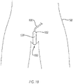
- FIG. 1B is a front view of a fluid collection device 100 in use on a female user 150.
- the fluid permeable body 120 of the fluid collection device is positioned adjacent to a urethra of the user 150.
- the fluid permeable body 120 is disposed within a chamber 104 (shown in FIGS. 2A and 2B ) of the fluid impermeable barrier 102 of the fluid collection device 100 and is exposed to the urethra of the user 150 through the opening 106 in the fluid collection device 100.
- the fluid collection device 100 can be secured to the user with any of a number of securing devices. Fluids received in the chamber 104 of the fluid collection device 100 from the urethra can be removed through the conduit 108.
- FIG. 2 is a cross-sectional view of the fluid collection device 100 taken along line 2-2 of FIG. 1 .
- the fluid collection device 100 also includes conduit 108 that is at least partially disposed in the chamber 104.
- the conduit 108 (e.g., a tube) includes an inlet 110 at a second end region 127 of the fluid impermeable barrier 102 and an outlet 112 at a first end region 125 of the fluid impermeable barrier 102 positioned downstream from the inlet 110.
- the conduit 108 provides fluid communication between an interior region of the chamber 104 and a fluid storage container (not shown) or a portable vacuum source (not shown).
- the conduit 108 may directly or indirectly fluidly couple the interior region of the chamber 104 and/or the reservoir 122 with the fluid storage container or the portable vacuum source.
- the fluid permeable body 120 defines a bore 202 extending through the fluid permeable body 120 from a first body end 121 of the fluid permeable body 120 to a second body end 123 of the fluid permeable body 120 distal to the first body end 120.
- the conduit 108 is at least partially disposed in the chamber 104 and interfaces at least a portion of the bore 202 of the fluid permeable body 120.
- the conduit 108 may extend into the fluid impermeable barrier 102 from the first end region 125 ( e.g ., proximate to the outlet 112) and may extend through the bore 202 to the second end region 127 ( e.g., opposite the first end region 125) to a point proximate to a reservoir 122 such that the inlet 110 is in fluid communication with the reservoir 122.
- the inlet 110 is positioned in the reservoir 122.
- the inlet 110 may be positioned flush with an end of the fluid permeable body 120 that partially defines the reservoir 122.
- the fluid collected in the fluid collection device 100 may be removed from the interior region of the chamber 104 via the conduit 108.
- the conduit 108 may include a flexible material such as plastic tubing ( e.g ., medical tubing).
- plastic tubing may include a thermoplastic elastomer, polyvinyl chloride, ethylene vinyl acetate, polytetrafluoroethylene, etc., tubing.
- the conduit 108 may include silicone or latex.
- the fluid impermeable barrier 102 can store fluids in a reservoir 122 therein.
- the reservoir 122 is an unoccupied portion of the chamber 104 and is void of other material.
- the reservoir 122 is defined partially by the fluid permeable body 120 and partially by the fluid impermeable barrier 102.
- the reservoir 122 is positioned in the second end region 127 of the chamber 104. In the illustrated embodiment, the reservoir 122 is defined by the second body end 123 of the fluid permeable body 120 and the second end region 127 of the fluid impermeable barrier 122.
- the fluid impermeable barrier 102 can be air permeable and fluid impermeable.
- the fluid impermeable barrier 102 can be formed of a hydrophobic material that defines a plurality of pores.
- one or more portions of at least the outer surface of the fluid impermeable barrier 102 can be formed from a soft and/or smooth material, thereby reducing chaffing.
- the fluid impermeable barrier 102 may include markings thereon, such as one or more markings to aid a user in aligning the device 100 on the wearer.
- a line on the fluid impermeable barrier 102 may allow a healthcare professional to align the opening 106 over the urethra of the wearer.
- the markings may include one or more of alignment guide or an orientation indicator, such as a stripe or hashes. Such markings may be positioned to align the device 100 to one or more anatomical features such as a pubic bone, etc.
- the fluid permeable body 120 and at least a portion of the conduit 108 can at least substantially completely fill the chamber 104.
- the fluid permeable body 120 and at least a portion of the conduit may not substantially completely fill the chamber 104.
- the fluid collection device 100 includes the reservoir 122 disposed in the chamber 104.
- the reservoir 122 is a substantially unoccupied portion of the chamber 104.
- the fluids that are in the chamber 104 can flow through the fluid permeable body 120 to the reservoir 122.
- the reservoir 122 can store at least some of the fluids therein.
- the fluid permeable body 120, at least a portion of the conduit 108, and the reservoir 122 can at least substantially completely fill the chamber 104.
- the reservoir 122 is located at the portion of the chamber 104 that is closest to the inlet 110 ( e.g ., the second end region).
- the fluid collection device 100 can include not only a first reservoir that is located at the portion of the chamber of the chamber 104 that is closest to the inlet 110 ( e.g. , second end region) but also a second reservoir that is located at the portion of the of the chamber 104 that is closest to the outlet 112 ( e.g ., first end region).
- the fluid impermeable barrier 102 and the fluid permeable body 120 are configured to have the conduit 108 at least partially disposed in the chamber 104. More specifically, the fluid permeable body 120 is configured to form a space that accommodates the conduit 108, namely the bore 202.
- the fluid impermeable barrier 102 defines an aperture 124 sized to receive the conduit 108 ( e.g ., at least one tube).
- the at least one conduit 108 is disposed in the chamber 104 via the aperture 124.
- the apertures 124 are configured to form an at least substantially fluid tight seal against the conduit 108 or the at least one tube thereby substantially preventing the fluids from escaping the chamber 104.
- the conduit 108 When secured to the fluid collection device 100, the conduit 108 is configured to provide fluid communication with and at least partially extend between one or more of a fluid storage containers (not shown) and a portable vacuum source (not shown).
- the conduit 108 may be configured to be fluidly coupled to and at least partially extend between one or more of the fluid storage containers and the portable vacuum source.
- the conduit 108 is configured to be directly connected to the portable vacuum source (not shown).
- the conduit 108 can extend from the fluid impermeable barrier 102 by at least 25 cm (one foot), at least 50 cm (two feet), at least 75 cm (three feet), or at least 150 cm (six feet).
- the conduit 108 is configured to be indirectly connected to at least one of the fluid storage container (not shown) or the portable vacuum source (not shown).
- the conduit may be frosted or opaque (e.g ., black) to obscure visibility of the fluids therein.
- the conduit is secured to a wearer's skin with a catheter securement device, such as a STATLOCK ® catheter securement device available from C. R. Bard, Inc., including but not limited to those disclosed in U.S. Patent Nos. 6,117,163 ; 6,123,398 ; and 8,211,063 .
- the inlet 110 and the outlet 112 are configured to provide fluid communication (e.g. , directly or indirectly) between the portable vacuum source (not shown) and the chamber 104 (e.g., the reservoir 122).
- the inlet 110 and the outlet 112 of the conduit 108 may be configured to directly or indirectly fluidly couple the portable vacuum source to the reservoir 122.
- the inlet 110 and/or the outlet 112 can form a male connector.
- the inlet 110 and/or the outlet 112 can form a female connector.
- the inlet 110 and/or the outlet 112 can include ribs that are configured to facilitate secure couplings.
- the inlet 110 and/or the outlet 112 can form a tapered shape.
- the inlet 110 and/or the outlet 112 can include a rigid or flexible material.
- Locating the inlet 110 at or near a gravimetrically low point of the chamber 104 enables the conduit to receive more of the fluids than if inlet 110 was located elsewhere and reduce the likelihood of pooling (e.g ., pooling of the fluids can cause microbe growth and foul odors).
- the fluids in the fluid permeable body 120 can flow in any direction due to capillary forces.
- the fluids may exhibit a preference to flow in the direction of gravity, especially when at least a portion of the fluid permeable body 120 is saturated with the fluids.
- the fluid(s) in the chamber 104 may be drawn into the inlet 110 and out of the fluid collection device 100 via the conduit 108.
- the conduit 108 is configured to be at least insertable into the chamber 104.
- the conduit 108 can include one or more markers 131 (shown in FIG. 1 ) on an exterior thereof that are configured to facilitate insertion of the conduit 108 into the chamber 104.
- the conduit 108 can include one or more markings thereon that are configured to prevent over or under insertion of the conduit 108, such as when the conduit 108 defines an inlet 110 that is configured to be disposed in or adjacent to the reservoir 122.
- the conduit 108 can include one or more markings thereon that are configured to facilitate correct rotation of the conduit 108 relative to the chamber 104.
- the one or more markings can include a line, a dot, a sticker, or any other suitable marking.
- the conduit 108 may extend into the fluid impermeable barrier 102 from the first end region ( e.g ., proximate to the outlet 112) and may extend to the second end region ( e.g ., opposite the first end region) to a point proximate to the reservoir 122 such that the inlet 110 is in fluid communication with the reservoir 122.
- the fluid collected in the fluid collection device 100 is removed from the interior region of the chamber 104 via the conduit 108.
- the conduit 108 may include a flexible material such as plastic tubing (e.g ., medical tubing) as disclosed herein.
- the conduit 108 may include one or more portions that are resilient, such as to by having one or more of a diameter or wall thickness that allows the conduit to be flexible.
- one or more components of the fluid collection device 100 can include an antimicrobial material, such as an antibacterial material where the fluid collection device may contact the wearer or the bodily fluid of the wearer.
- the antimicrobial material can include an antimicrobial coating, such as a nitrofurazone or silver coating.
- the antimicrobial material can inhibit microbial growth, such as microbial growth due to pooling or stagnation of the fluids.
- one or more components of the fluid collection device 100 e.g ., impermeable barrier 102, conduit 108, etc.
- an odor blocking or absorbing material such as a cyclodextrine containing material or a thermoplastic elastomer (TPE) polymer.
- the conduits 108 may include or be operably coupled to a flow meter (not shown) to measure the flow of fluids therein, one or more securement devices (e.g. , a StatLock securement device, not shown) or fittings to secure the conduit 108 to one or more components of the systems or devices disclosed herein (e.g ., portable vacuum source or fluid storage container), or one or more valves to control the flow of fluids in the systems and devices herein.
- a flow meter not shown
- securement devices e.g. , a StatLock securement device, not shown
- fittings to secure the conduit 108 to one or more components of the systems or devices disclosed herein (e.g ., portable vacuum source or fluid storage container), or one or more valves to control the flow of fluids in the systems and devices herein.
- At least one of portion of the conduit 108 of the fluid collection devices or systems herein can be formed of an at least partially opaque material which can obscure the fluids that are present therein.
- the B section of the conduits 108 disclosed herein may be formed of an opaque material or translucent material while the A section may be formed of a transparent material or translucent material.
- the B section may include transparent or translucent material. Unlike the opaque or nearly opaque material, the translucent material allows a user of the devices and systems herein to visually identify fluids or issues that are inhibiting the flow of fluids within the conduit 108.
- the system of fluid collection device may include moisture sensors (not shown) disposed inside of the chamber of the fluid collection device.
- the moisture sensor may be operably coupled to a controller or directly to the portable vacuum source, and may provide electrical signals indicating that moisture is or is not detected in one or more portions of the chamber.
- the moisture sensor(s) may provide an indication that moisture is present, and responsive thereto, the controller or portable vacuum device may direct the initiation of suction to the chamber to remove the fluid therefrom.
- Suitable moisture sensors may include capacitance sensors, volumetric sensors, potential sensors, resistance sensors, frequency domain reflectometry sensors, time domain reflectometry sensors, or any other suitable moisture sensor.
- the moisture sensors may detect moisture in the chamber and may provide a signal to the controller or portable vacuum source to activate the portable suction device.
- FIG. 4 is a flow diagram of a method 400 of assembling the fluid collection devices and/or fluid collection systems disclosed herein, according to an embodiment.
- the method 400 includes act 405, which recites providing a fluid impermeable barrier.
- the fluid impermeable barrier at least partially defines a chamber and also an opening extending therethrough.
- the opening is configured to be positioned adjacent to a female urethra.
- the fluid permeable body consists of a singular porous hydrophilic polyolefin material extruded to a substantially cylindrical shape.
- the method includes act 410, which recites inserting a substantially cylindrical and fluid permeable body into the chamber of the fluid impermeable barrier.
- the fluid permeable body interfaces at least a portion of the fluid impermeable barrier and covers at least a portion of the opening.
- the fluid permeable body includes a singular porous material that is substantially cylindrical in shape and configured to wick any fluid away from the opening.
- Act 410 includes inserting the fluid permeable body into the chamber of the fluid impermeable barrier such that a reservoir is defined within the chamber by a second body end of the fluid permeable body distal to the first body end and a second end region of the fluid impermeable barrier distal to the aperture.
- act 410 can include inserting the substantially cylindrical and fluid permeable body into the chamber of the fluid impermeable barrier such that the fluid permeable body and the conduit fill substantially all of the chamber.
- the method includes act 415, which recites inserting an inlet of a conduit into the fluid impermeable body.
- the conduit can be inserted into the fluid impermeable body through an aperture defined by the fluid impermeable barrier at a first end region of the fluid impermeable barrier.
- act 415 can include inserting the inlet of the conduit into the bore at the first body end, through the bore of the fluid permeable body, through the second body end of the fluid permeable body, and into the reservoir such that the conduit extends from the reservoir, through the fluid permeable body, through the aperture to outside the fluid impermeable barrier.
- the method includes an act 420, which recites inserting the inlet of the conduit into a bore at a first body end of the fluid permeable body.
- the bore extends through the fluid permeable body and is defined by the fluid permeable body.
- the conduit interfaces at least a portion of the fluid permeable body.
- the acts 405, 410, 415, and 420 include using the fluid collection device defined in claim 1.
- FIG. 6 is a flow diagram of a non-claimed method 600 for collecting fluids.
- the method 600 includes an act 605 of positioning a fluid permeable body of a fluid collection device adjacent to a female urethra of a user.
- the fluid permeable body is disposed within a chamber of a fluid impermeable barrier of the fluid collection device and exposed to the female urethra of the user through an opening in the fluid collection device defined by the fluid impermeable barrier.
- the method 600 also includes an act 610 of securing the fluid collection device to the user.
- the method 600 also includes an act 615 of receiving fluids from the female urethra into the chamber of the fluid collection device.
- the method 600 an act of applying suction effective to suction the fluids from the chamber via a conduit disposed therein.
Landscapes
- Health & Medical Sciences (AREA)
- Heart & Thoracic Surgery (AREA)
- General Health & Medical Sciences (AREA)
- Public Health (AREA)
- Engineering & Computer Science (AREA)
- Biomedical Technology (AREA)
- Veterinary Medicine (AREA)
- Vascular Medicine (AREA)
- Life Sciences & Earth Sciences (AREA)
- Animal Behavior & Ethology (AREA)
- Epidemiology (AREA)
- Orthopedic Medicine & Surgery (AREA)
- Nursing (AREA)
- Anesthesiology (AREA)
- Hematology (AREA)
- Reproductive Health (AREA)
- Orthopedics, Nursing, And Contraception (AREA)
- External Artificial Organs (AREA)
- Prostheses (AREA)
- Extraction Or Liquid Replacement (AREA)
- Physical Or Chemical Processes And Apparatus (AREA)
Priority Applications (1)
| Application Number | Priority Date | Filing Date | Title |
|---|---|---|---|
| EP22181857.8A EP4112016A1 (en) | 2018-05-02 | 2019-04-29 | Fluid collection devices, systems, and methods |
Applications Claiming Priority (2)
| Application Number | Priority Date | Filing Date | Title |
|---|---|---|---|
| US201862665711P | 2018-05-02 | 2018-05-02 | |
| PCT/US2019/029616 WO2019212956A1 (en) | 2018-05-02 | 2019-04-29 | Fluid collection devices, systems, and methods |
Related Child Applications (1)
| Application Number | Title | Priority Date | Filing Date |
|---|---|---|---|
| EP22181857.8A Division EP4112016A1 (en) | 2018-05-02 | 2019-04-29 | Fluid collection devices, systems, and methods |
Publications (2)
| Publication Number | Publication Date |
|---|---|
| EP3787572A1 EP3787572A1 (en) | 2021-03-10 |
| EP3787572B1 true EP3787572B1 (en) | 2022-07-06 |
Family
ID=66476858
Family Applications (2)
| Application Number | Title | Priority Date | Filing Date |
|---|---|---|---|
| EP19723279.6A Active EP3787572B1 (en) | 2018-05-02 | 2019-04-29 | Fluid collection devices, systems, and methods |
| EP22181857.8A Pending EP4112016A1 (en) | 2018-05-02 | 2019-04-29 | Fluid collection devices, systems, and methods |
Family Applications After (1)
| Application Number | Title | Priority Date | Filing Date |
|---|---|---|---|
| EP22181857.8A Pending EP4112016A1 (en) | 2018-05-02 | 2019-04-29 | Fluid collection devices, systems, and methods |
Country Status (10)
| Country | Link |
|---|---|
| US (1) | US20210236324A1 (https=) |
| EP (2) | EP3787572B1 (https=) |
| JP (1) | JP7239613B2 (https=) |
| KR (1) | KR102599284B1 (https=) |
| CN (1) | CN112312867A (https=) |
| AU (1) | AU2019262946B2 (https=) |
| CA (1) | CA3098882C (https=) |
| ES (1) | ES2926022T3 (https=) |
| SA (1) | SA520420441B1 (https=) |
| WO (1) | WO2019212956A1 (https=) |
Families Citing this family (70)
| Publication number | Priority date | Publication date | Assignee | Title |
|---|---|---|---|---|
| US10952889B2 (en) | 2016-06-02 | 2021-03-23 | Purewick Corporation | Using wicking material to collect liquid for transport |
| US10390989B2 (en) | 2014-03-19 | 2019-08-27 | Purewick Corporation | Apparatus and methods for receiving discharged urine |
| US11376152B2 (en) | 2014-03-19 | 2022-07-05 | Purewick Corporation | Apparatus and methods for receiving discharged urine |
| US11806266B2 (en) | 2014-03-19 | 2023-11-07 | Purewick Corporation | Apparatus and methods for receiving discharged urine |
| US10226376B2 (en) | 2014-03-19 | 2019-03-12 | Purewick Corporation | Apparatus and methods for receiving discharged urine |
| US10973678B2 (en) | 2016-07-27 | 2021-04-13 | Purewick Corporation | Apparatus and methods for receiving discharged urine |
| US10376406B2 (en) | 2016-07-27 | 2019-08-13 | Purewick Corporation | Male urine collection device using wicking material |
| WO2018144463A1 (en) | 2017-01-31 | 2018-08-09 | Purewick Corporation | Apparatus and methods for receiving discharged urine |
| EP3787569B1 (en) | 2018-05-01 | 2025-07-16 | Purewick Corporation | Fluid collection devices and systems |
| AU2019262939A1 (en) | 2018-05-01 | 2020-11-26 | Purewick Corporation | Fluid collection devices, systems, and methods |
| AU2019262945B2 (en) | 2018-05-01 | 2022-08-25 | Purewick Corporation | Fluid collection devices and methods of using the same |
| JP7072084B2 (ja) | 2018-05-01 | 2022-05-19 | ピュアウィック コーポレイション | 流体収集装置、関連システム、及び関連方法 |
| US11944740B2 (en) | 2018-05-01 | 2024-04-02 | Purewick Corporation | Fluid collection devices, related systems, and related methods |
| CA3143904C (en) | 2019-06-21 | 2023-11-28 | Purewick Corporation | Fluid collection devices including a base securement area, and related systems and methods |
| ES2961269T3 (es) | 2019-07-11 | 2024-03-11 | Purewick Corp | Dispositivos y sistemas de recogida de líquido |
| WO2021016026A1 (en) | 2019-07-19 | 2021-01-28 | Purewick Corporation | Fluid collection devices including at least one shape memory material |
| EP4051190B1 (en) | 2019-10-28 | 2024-05-22 | Purewick Corporation | Fluid collection assemblies including a sample port |
| EP4559443A3 (en) | 2020-01-03 | 2025-06-18 | Purewick Corporation | Urine collection devices having a relatively wide portion and an elongated portion and related methods |
| WO2021188817A1 (en) | 2020-03-19 | 2021-09-23 | Purewick Corporation | Fluid collection assemblies including one or more movement enhancing features |
| US12521288B2 (en) | 2020-03-26 | 2026-01-13 | Purewick Corporation | Multi-layer urine capture device and related methods |
| WO2021207621A1 (en) | 2020-04-10 | 2021-10-14 | Purewick Corporation | Fluid collection assemblies including one or more leak prevention features |
| WO2021211801A1 (en) | 2020-04-17 | 2021-10-21 | Purewick Corporation | Fluid collection assemblies including a fluid impermeable barrier having a sump and a base |
| US12465514B2 (en) | 2020-04-17 | 2025-11-11 | Purewick Corporation | Fluid collection devices, systems, and methods securing a protruding portion in position for use |
| US12472090B2 (en) | 2020-04-17 | 2025-11-18 | Purewick Corporation | Female external catheter devices having a urethral cup, and related systems and methods |
| US12491104B2 (en) | 2020-04-20 | 2025-12-09 | Purewick Corporation | Fluid collection devices adjustable between a vacuum-based orientation and a gravity-based orientation, and related systems and methods |
| US11207206B2 (en) | 2020-05-14 | 2021-12-28 | Cm Technologies, Inc. | Fluid removal device |
| US12048643B2 (en) | 2020-05-27 | 2024-07-30 | Purewick Corporation | Fluid collection assemblies including at least one inflation device and methods and systems of using the same |
| US11504265B2 (en) | 2020-06-18 | 2022-11-22 | Medline Industries, Lp | Urine collection device, system, and method |
| USD967409S1 (en) | 2020-07-15 | 2022-10-18 | Purewick Corporation | Urine collection apparatus cover |
| WO2022031798A1 (en) | 2020-08-04 | 2022-02-10 | Cm Technologies, Inc. | Fecal management systems and methods |
| EP4192402A1 (en) * | 2020-08-05 | 2023-06-14 | Purewick Corporation | Fluid collection devices and systems including an adhesive securement feature, and methods of use |
| US12440371B2 (en) | 2020-08-06 | 2025-10-14 | Purewick Corporation | Fluid collection system including a garment and a fluid collection device |
| US12350187B2 (en) | 2020-08-11 | 2025-07-08 | Purewick Corporation | Fluid collection assemblies defining waist and leg openings |
| EP4210643A1 (en) | 2020-09-09 | 2023-07-19 | Purewick Corporation | Fluid collection devices, systems, and methods |
| US12156792B2 (en) | 2020-09-10 | 2024-12-03 | Purewick Corporation | Fluid collection assemblies including at least one inflation device |
| US11801186B2 (en) | 2020-09-10 | 2023-10-31 | Purewick Corporation | Urine storage container handle and lid accessories |
| US12042423B2 (en) | 2020-10-07 | 2024-07-23 | Purewick Corporation | Fluid collection systems including at least one tensioning element |
| US12440370B2 (en) | 2020-10-21 | 2025-10-14 | Purewick Corporation | Apparatus with compressible casing for receiving discharged urine |
| US12569365B2 (en) | 2020-10-21 | 2026-03-10 | Purewick Corporation | Fluid collection assemblies including at least one shape memory material disposed in the conduit |
| US12208031B2 (en) | 2020-10-21 | 2025-01-28 | Purewick Corporation | Adapters for fluid collection devices |
| US12257174B2 (en) | 2020-10-21 | 2025-03-25 | Purewick Corporation | Fluid collection assemblies including at least one of a protrusion or at least one expandable material |
| EP4240297B1 (en) * | 2020-11-03 | 2025-12-03 | Purewick Corporation | Male external catheter including nonwoven fabric |
| US12048644B2 (en) | 2020-11-03 | 2024-07-30 | Purewick Corporation | Apparatus for receiving discharged urine |
| US12070432B2 (en) | 2020-11-11 | 2024-08-27 | Purewick Corporation | Urine collection system including a flow meter and related methods |
| US12245967B2 (en) | 2020-11-18 | 2025-03-11 | Purewick Corporation | Fluid collection assemblies including an adjustable spine |
| US12599495B2 (en) | 2021-01-05 | 2026-04-14 | Purewick Corporation | Male external catheter with attachment interface configured to bias against penis |
| US12268627B2 (en) | 2021-01-06 | 2025-04-08 | Purewick Corporation | Fluid collection assemblies including at least one securement body |
| JP2024503636A (ja) | 2021-01-07 | 2024-01-26 | ピュアウィック コーポレイション | 車椅子に固定可能な尿収集システムおよび関連する方法 |
| EP4349306A3 (en) | 2021-01-19 | 2024-06-05 | Purewick Corporation | Variable fit fluid collection devices |
| CN117120008A (zh) * | 2021-02-08 | 2023-11-24 | 普利维克公司 | 可枢转的流体收集设备管连接器以及相关系统和方法 |
| US12178735B2 (en) | 2021-02-09 | 2024-12-31 | Purewick Corporation | Noise reduction for a urine suction system |
| JP2022131362A (ja) * | 2021-02-26 | 2022-09-07 | 大和ハウス工業株式会社 | 排泄物処理装置 |
| EP4274524B1 (en) | 2021-02-26 | 2024-08-28 | Purewick Corporation | A male fluid collection device configured as a male urine collection device |
| US12558472B2 (en) | 2021-03-05 | 2026-02-24 | Purewick Corporation | Portable fluid collection systems with storage and related methods |
| US12551385B2 (en) | 2021-03-05 | 2026-02-17 | Purewick Corporation | Fluid collection assembly including a tube having porous wicking material for improved fluid transport |
| US12458525B2 (en) | 2021-03-10 | 2025-11-04 | Purewick Corporation | Acoustic silencer for a urine suction system |
| US11938054B2 (en) | 2021-03-10 | 2024-03-26 | Purewick Corporation | Bodily waste and fluid collection with sacral pad |
| US12029677B2 (en) | 2021-04-06 | 2024-07-09 | Purewick Corporation | Fluid collection devices having a collection bag, and related systems and methods |
| AU2022253886B2 (en) * | 2021-04-09 | 2025-02-20 | Purewick Corporation | Conduits including at least one conduit porous material |
| WO2022232354A1 (en) * | 2021-04-29 | 2022-11-03 | Purewick Corporation | Drainage bags with at least one fluid detector |
| US12233003B2 (en) | 2021-04-29 | 2025-02-25 | Purewick Corporation | Fluid collection assemblies including at least one length adjusting feature |
| US12251333B2 (en) | 2021-05-21 | 2025-03-18 | Purewick Corporation | Fluid collection assemblies including at least one inflation device and methods and systems of using the same |
| US12324767B2 (en) | 2021-05-24 | 2025-06-10 | Purewick Corporation | Fluid collection assembly including a customizable external support and related methods |
| US12150885B2 (en) | 2021-05-26 | 2024-11-26 | Purewick Corporation | Fluid collection system including a cleaning system and methods |
| US20220395391A1 (en) * | 2021-06-11 | 2022-12-15 | Triton Systems, Inc. | Bladder collection system |
| US12575960B2 (en) | 2021-06-24 | 2026-03-17 | Purewick Corporation | Urine collection systems having one or more of volume, pressure, or flow indicators, and related methods |
| US12551366B2 (en) | 2021-08-02 | 2026-02-17 | Purewick Corporation | Fluid collection devices having multiple fluid collection regions, and related systems and methods |
| US12594062B2 (en) | 2021-09-08 | 2026-04-07 | Purewick Corporation | Fluid collection assemblies including an extension |
| USD1041003S1 (en) | 2022-02-10 | 2024-09-03 | Medline Industries, Lp | Catheter connector |
| US20230293339A1 (en) * | 2022-03-21 | 2023-09-21 | II Gary Bruce James | Absorbent Hygienic Article Having an Integrated Drainage Mechanism |
Family Cites Families (78)
| Publication number | Priority date | Publication date | Assignee | Title |
|---|---|---|---|---|
| US4246901A (en) * | 1978-05-30 | 1981-01-27 | Nasa | Urine collection device |
| WO1980000535A1 (en) * | 1978-09-15 | 1980-04-03 | A Christensen | Urinal |
| US4257418A (en) * | 1979-01-22 | 1981-03-24 | Mo Och Domsjo Aktiebolag | Device for absorbing urine with incontinent persons |
| US4568341A (en) * | 1982-03-10 | 1986-02-04 | James G. Mitchell | Absorbent pads, incontinence care products and methods of production |
| US4553968A (en) * | 1983-06-09 | 1985-11-19 | Glenna Komis | External male urinary catheter with garment |
| US4610675A (en) * | 1983-09-06 | 1986-09-09 | David Triunfol | Device for collecting fluid discharged from female organs |
| US4681577A (en) * | 1983-09-23 | 1987-07-21 | Personal Products Company | Disposable urinary and fecal waste containment product |
| GB8328624D0 (en) * | 1983-10-26 | 1983-11-30 | Secr Social Service Brit | Incontinence devices |
| US4905692A (en) * | 1984-01-10 | 1990-03-06 | K. T. Medical, Inc. | Medical and orthopedic support fabric |
| US5002541A (en) * | 1984-06-19 | 1991-03-26 | Martin And Associates, Inc. | Method and device for removing and collecting urine |
| US4631061A (en) * | 1984-06-19 | 1986-12-23 | Martin Frank D | Automatic urine detecting, collecting and storing device |
| JPS61199861A (ja) * | 1985-03-02 | 1986-09-04 | 池末 英明 | 排尿器具 |
| US4904248A (en) * | 1986-02-18 | 1990-02-27 | Sherwood Medical Company | Female incontinent urine collection device |
| WO1988004558A1 (en) * | 1986-12-22 | 1988-06-30 | Conkling J Michael | Urine sensing, collecting and storage device |
| US4747166A (en) * | 1987-05-15 | 1988-05-31 | Kuntz David H | Fluid aspiration system for the management of urinary incontinence |
| US5031248A (en) * | 1987-07-29 | 1991-07-16 | Innovec, Inc. | Disposable panty |
| US4813943A (en) * | 1987-08-17 | 1989-03-21 | Smith Samuel C | Urinary incontinence collector |
| US4886508A (en) * | 1988-07-11 | 1989-12-12 | Washington Douglas L | Ladies external catheter assembly |
| WO1991004714A2 (en) * | 1989-09-29 | 1991-04-18 | Washington Douglas L | Compact universal catheter assembly |
| CA2037210A1 (en) * | 1990-10-16 | 1992-04-17 | Neal Alan Rollins | Disposable feminine guard |
| US5330457A (en) * | 1991-09-30 | 1994-07-19 | Hercules Incorporated | Enhanced core utilization in absorbent products |
| JP3137130B2 (ja) * | 1991-11-01 | 2001-02-19 | アルケア株式会社 | 女性用採尿器 |
| DE69217078T2 (de) * | 1991-11-20 | 1997-05-07 | Urohealth Inc California | Unterlage für die behandlung von urininkontinenz |
| US5195997A (en) * | 1991-11-27 | 1993-03-23 | Carns William A | Incontinent's aid |
| US5678564A (en) * | 1992-08-07 | 1997-10-21 | Bristol Myers Squibb | Liquid removal system |
| US5267988A (en) * | 1992-11-25 | 1993-12-07 | Farkas Barry L | Non-invasive female urine collection device |
| US5411495A (en) * | 1993-12-20 | 1995-05-02 | Willingham; Clara J. | Systems for receiving and storing urine from a female patient |
| US5637098A (en) | 1995-08-07 | 1997-06-10 | Venetec International, Inc. | Catheter securement device |
| DE19619597A1 (de) * | 1996-05-15 | 1997-11-20 | Walter Frenkel | Entsorgungsgerät für menschliche Ausscheidungen |
| US5957904A (en) * | 1996-10-24 | 1999-09-28 | Holland; Marlan J. | External urinary collection pouch for females |
| JP3419659B2 (ja) | 1997-09-18 | 2003-06-23 | 本田技研工業株式会社 | 車両の走行安定装置 |
| CA2354132A1 (en) * | 1998-12-22 | 2000-06-29 | The Procter & Gamble Company | Absorbent article for wearing in supporting garment |
| AU776398B2 (en) * | 1998-12-30 | 2004-09-09 | Mcneil-Ppc, Inc. | Body-attachable interlabial articles and methods for making the same |
| GB9906888D0 (en) * | 1999-03-26 | 1999-05-19 | Univ Brunel | Active urine collection device |
| US20040015141A1 (en) * | 2000-04-06 | 2004-01-22 | Cheng Gordon C. | Urine management system for human females |
| US20040176731A1 (en) * | 2000-04-06 | 2004-09-09 | Cheng Gordon C. | Personal urine management system for humans |
| US6569133B2 (en) * | 2000-04-06 | 2003-05-27 | Uroscientific, Inc. | Urine management system for human females |
| US20030120178A1 (en) * | 2001-12-20 | 2003-06-26 | The Procter & Gamble Company | Supplemental interlabial device |
| JP4267379B2 (ja) * | 2003-06-11 | 2009-05-27 | ユニ・チャーム株式会社 | 自動排尿処理装置およびそれに用いる尿レシーバ |
| TWI248809B (en) * | 2003-08-06 | 2006-02-11 | Hitachi Ltd | Automatic urine disposal device and urine receptacle used therefor |
| JP4283631B2 (ja) * | 2003-09-30 | 2009-06-24 | 株式会社日立製作所 | 自動排尿処理装置およびそれに用いる尿レシーバ |
| FR2862526B1 (fr) * | 2003-11-20 | 2006-09-29 | Maria Seignez | Systeme collecteur d'urine et pantalon special incontinence |
| US7931634B2 (en) * | 2003-12-18 | 2011-04-26 | Kimberly-Clark Worldwide, Inc. | Bodily exudate capturing article |
| US7901389B2 (en) * | 2004-03-03 | 2011-03-08 | Avec Scientific Design Corporation | Liquid removal method and apparatus for surgical procedures |
| US20060069359A1 (en) * | 2004-09-30 | 2006-03-30 | Dipalma Joseph | Body fluid collection system |
| GB0520864D0 (en) * | 2005-10-13 | 2005-11-23 | Univ Brunel | Urine collection device |
| US8211063B2 (en) | 2006-04-07 | 2012-07-03 | Venetec International, Inc. | Side loaded securement device |
| JP2008132240A (ja) * | 2006-11-29 | 2008-06-12 | Kao Corp | 吸収性物品 |
| WO2009052496A1 (en) * | 2007-10-18 | 2009-04-23 | Convatec Inc. | Aspiration system for removing liquid discharged by the human body, and liquid sensor therefor |
| JP4384694B2 (ja) * | 2008-02-13 | 2009-12-16 | ユニ・チャーム株式会社 | 吸尿装置 |
| JP5358103B2 (ja) * | 2008-02-14 | 2013-12-04 | ユニ・チャーム株式会社 | 自動尿処理装置 |
| US20100036348A1 (en) * | 2008-08-05 | 2010-02-11 | Antonio Carlos Ribeiro De Carvalho | Absorbent article including absorbent core having a plurality of first regions and a second region surrounding each of the first regions |
| EP2380532B1 (en) * | 2008-09-19 | 2014-12-03 | Unicharm Corporation | Urine receiver and wearing article |
| JP5540373B2 (ja) * | 2009-06-04 | 2014-07-02 | 王子ホールディングス株式会社 | 男性用尿パッド |
| US20120103347A1 (en) * | 2009-06-26 | 2012-05-03 | Hollister Incorporated | Urinary incontinence device and method |
| JP5370963B2 (ja) * | 2009-08-05 | 2013-12-18 | 王子ホールディングス株式会社 | 吸収性物品 |
| JP5396232B2 (ja) * | 2009-10-23 | 2014-01-22 | ユニ・チャーム株式会社 | 排便検出装置 |
| US8287508B1 (en) * | 2010-07-21 | 2012-10-16 | Sanchez Robert A | Using moisture-wicking article wrapped over openings in an elongated urine collecting container for drawing urine from a region surrounding an urethral opening |
| US10390989B2 (en) * | 2014-03-19 | 2019-08-27 | Purewick Corporation | Apparatus and methods for receiving discharged urine |
| US10226376B2 (en) * | 2014-03-19 | 2019-03-12 | Purewick Corporation | Apparatus and methods for receiving discharged urine |
| US10952889B2 (en) * | 2016-06-02 | 2021-03-23 | Purewick Corporation | Using wicking material to collect liquid for transport |
| US11806266B2 (en) * | 2014-03-19 | 2023-11-07 | Purewick Corporation | Apparatus and methods for receiving discharged urine |
| US20150305917A1 (en) * | 2014-04-29 | 2015-10-29 | Sophia Hai Yun SU | Urine Collector |
| JP5719079B1 (ja) * | 2014-07-11 | 2015-05-13 | 住友精化株式会社 | 吸水性樹脂及び吸収性物品 |
| GB201417457D0 (en) * | 2014-10-02 | 2014-11-19 | Kalitasha Ltd | Hygiene device |
| WO2016123500A1 (en) | 2015-01-27 | 2016-08-04 | Medivance Incorporated | Improved medical pad and system for thermotherapy |
| CN204562697U (zh) * | 2015-04-10 | 2015-08-19 | 重庆医科大学附属永川医院 | 充气式无缝男用接尿器 |
| US10806623B2 (en) * | 2016-03-29 | 2020-10-20 | Spectrum Health Innovation, Llc | External female urine collection system and related method |
| AU2017275649B2 (en) * | 2016-06-02 | 2019-08-01 | Purewick Corporation | Apparatus and methods for receiving discharged urine |
| US10973678B2 (en) * | 2016-07-27 | 2021-04-13 | Purewick Corporation | Apparatus and methods for receiving discharged urine |
| US10376406B2 (en) * | 2016-07-27 | 2019-08-13 | Purewick Corporation | Male urine collection device using wicking material |
| US10376407B2 (en) * | 2016-08-16 | 2019-08-13 | Purewick Corporation | Using wicking material to collect urine from a male for transport |
| WO2018144463A1 (en) * | 2017-01-31 | 2018-08-09 | Purewick Corporation | Apparatus and methods for receiving discharged urine |
| WO2018152156A1 (en) * | 2017-02-14 | 2018-08-23 | Sage Products, Llc | Devices and methods for urine collection |
| US11944740B2 (en) * | 2018-05-01 | 2024-04-02 | Purewick Corporation | Fluid collection devices, related systems, and related methods |
| AU2019262945B2 (en) * | 2018-05-01 | 2022-08-25 | Purewick Corporation | Fluid collection devices and methods of using the same |
| EP3787569B1 (en) * | 2018-05-01 | 2025-07-16 | Purewick Corporation | Fluid collection devices and systems |
| GB2612752B (en) * | 2020-09-29 | 2023-12-06 | Martin Baker Aircraft Co Ltd | A urine collection system |
-
2019
- 2019-04-29 EP EP19723279.6A patent/EP3787572B1/en active Active
- 2019-04-29 CN CN201980038454.9A patent/CN112312867A/zh active Pending
- 2019-04-29 ES ES19723279T patent/ES2926022T3/es active Active
- 2019-04-29 AU AU2019262946A patent/AU2019262946B2/en active Active
- 2019-04-29 EP EP22181857.8A patent/EP4112016A1/en active Pending
- 2019-04-29 US US17/051,600 patent/US20210236324A1/en active Pending
- 2019-04-29 JP JP2020561793A patent/JP7239613B2/ja active Active
- 2019-04-29 WO PCT/US2019/029616 patent/WO2019212956A1/en not_active Ceased
- 2019-04-29 CA CA3098882A patent/CA3098882C/en active Active
- 2019-04-29 KR KR1020207034753A patent/KR102599284B1/ko active Active
-
2020
- 2020-10-28 SA SA520420441A patent/SA520420441B1/ar unknown
Also Published As
| Publication number | Publication date |
|---|---|
| EP3787572A1 (en) | 2021-03-10 |
| JP7239613B2 (ja) | 2023-03-14 |
| AU2019262946A1 (en) | 2020-11-26 |
| KR102599284B1 (ko) | 2023-11-08 |
| KR20210021965A (ko) | 2021-03-02 |
| CN112312867A (zh) | 2021-02-02 |
| US20210236324A1 (en) | 2021-08-05 |
| ES2926022T3 (es) | 2022-10-21 |
| EP4112016A1 (en) | 2023-01-04 |
| JP2021522022A (ja) | 2021-08-30 |
| CA3098882C (en) | 2023-09-19 |
| WO2019212956A1 (en) | 2019-11-07 |
| BR112020022326A2 (pt) | 2021-02-02 |
| SA520420441B1 (ar) | 2024-05-09 |
| AU2019262946B2 (en) | 2022-06-23 |
| CA3098882A1 (en) | 2019-11-07 |
Similar Documents
| Publication | Publication Date | Title |
|---|---|---|
| EP3787572B1 (en) | Fluid collection devices, systems, and methods | |
| CA3146352C (en) | Fluid collection devices including an opening having an increased width, and systems and methods of use | |
| US20260047956A1 (en) | Fluid collection devices including a base securement area, and related systems and methods | |
| US20220039995A1 (en) | Fluid collection devices including an enlarged base, and systems and methods of use | |
| EP3787569B1 (en) | Fluid collection devices and systems | |
| EP3787573B1 (en) | Fluid collection devices and methods of using the same | |
| EP4208133B1 (en) | Fluid collection devices and systems having one or more securement straps, and methods of use | |
| US12575961B2 (en) | Fluid collection devices, systems, and methods | |
| US20240058157A1 (en) | Fluid collection devices and systems including an adhesive securement feature, and methods of use | |
| US20220226144A1 (en) | Fluid collection devices and systems having a fluid impermeable barrier with a selectively minimal hardness, thickness, and/or modulus of elasticity | |
| US20240415689A1 (en) | Pad-shaped female external catheter and related systems and methods | |
| BR112020022326B1 (pt) | Dispositivo de coleta de fluido e método de montar um dispositivo de coleta de fluido |
Legal Events
| Date | Code | Title | Description |
|---|---|---|---|
| STAA | Information on the status of an ep patent application or granted ep patent |
Free format text: STATUS: UNKNOWN |
|
| STAA | Information on the status of an ep patent application or granted ep patent |
Free format text: STATUS: THE INTERNATIONAL PUBLICATION HAS BEEN MADE |
|
| PUAI | Public reference made under article 153(3) epc to a published international application that has entered the european phase |
Free format text: ORIGINAL CODE: 0009012 |
|
| STAA | Information on the status of an ep patent application or granted ep patent |
Free format text: STATUS: REQUEST FOR EXAMINATION WAS MADE |
|
| 17P | Request for examination filed |
Effective date: 20201110 |
|
| AK | Designated contracting states |
Kind code of ref document: A1 Designated state(s): AL AT BE BG CH CY CZ DE DK EE ES FI FR GB GR HR HU IE IS IT LI LT LU LV MC MK MT NL NO PL PT RO RS SE SI SK SM TR |
|
| AX | Request for extension of the european patent |
Extension state: BA ME |
|
| STAA | Information on the status of an ep patent application or granted ep patent |
Free format text: STATUS: EXAMINATION IS IN PROGRESS |
|
| DAV | Request for validation of the european patent (deleted) | ||
| DAX | Request for extension of the european patent (deleted) | ||
| 17Q | First examination report despatched |
Effective date: 20210810 |
|
| GRAP | Despatch of communication of intention to grant a patent |
Free format text: ORIGINAL CODE: EPIDOSNIGR1 |
|
| STAA | Information on the status of an ep patent application or granted ep patent |
Free format text: STATUS: GRANT OF PATENT IS INTENDED |
|
| INTG | Intention to grant announced |
Effective date: 20220422 |
|
| GRAS | Grant fee paid |
Free format text: ORIGINAL CODE: EPIDOSNIGR3 |
|
| GRAA | (expected) grant |
Free format text: ORIGINAL CODE: 0009210 |
|
| STAA | Information on the status of an ep patent application or granted ep patent |
Free format text: STATUS: THE PATENT HAS BEEN GRANTED |
|
| AK | Designated contracting states |
Kind code of ref document: B1 Designated state(s): AL AT BE BG CH CY CZ DE DK EE ES FI FR GB GR HR HU IE IS IT LI LT LU LV MC MK MT NL NO PL PT RO RS SE SI SK SM TR |
|
| REG | Reference to a national code |
Ref country code: AT Ref legal event code: REF Ref document number: 1502338 Country of ref document: AT Kind code of ref document: T Effective date: 20220715 Ref country code: CH Ref legal event code: EP |
|
| REG | Reference to a national code |
Ref country code: DE Ref legal event code: R096 Ref document number: 602019016701 Country of ref document: DE |
|
| REG | Reference to a national code |
Ref country code: NL Ref legal event code: FP Ref country code: IE Ref legal event code: FG4D |
|
| REG | Reference to a national code |
Ref country code: SE Ref legal event code: TRGR |
|
| REG | Reference to a national code |
Ref country code: ES Ref legal event code: FG2A Ref document number: 2926022 Country of ref document: ES Kind code of ref document: T3 Effective date: 20221021 |
|
| REG | Reference to a national code |
Ref country code: LT Ref legal event code: MG9D |
|
| PG25 | Lapsed in a contracting state [announced via postgrant information from national office to epo] |
Ref country code: RS Free format text: LAPSE BECAUSE OF FAILURE TO SUBMIT A TRANSLATION OF THE DESCRIPTION OR TO PAY THE FEE WITHIN THE PRESCRIBED TIME-LIMIT Effective date: 20220706 Ref country code: PT Free format text: LAPSE BECAUSE OF FAILURE TO SUBMIT A TRANSLATION OF THE DESCRIPTION OR TO PAY THE FEE WITHIN THE PRESCRIBED TIME-LIMIT Effective date: 20221107 Ref country code: NO Free format text: LAPSE BECAUSE OF FAILURE TO SUBMIT A TRANSLATION OF THE DESCRIPTION OR TO PAY THE FEE WITHIN THE PRESCRIBED TIME-LIMIT Effective date: 20221006 Ref country code: LV Free format text: LAPSE BECAUSE OF FAILURE TO SUBMIT A TRANSLATION OF THE DESCRIPTION OR TO PAY THE FEE WITHIN THE PRESCRIBED TIME-LIMIT Effective date: 20220706 Ref country code: LT Free format text: LAPSE BECAUSE OF FAILURE TO SUBMIT A TRANSLATION OF THE DESCRIPTION OR TO PAY THE FEE WITHIN THE PRESCRIBED TIME-LIMIT Effective date: 20220706 Ref country code: FI Free format text: LAPSE BECAUSE OF FAILURE TO SUBMIT A TRANSLATION OF THE DESCRIPTION OR TO PAY THE FEE WITHIN THE PRESCRIBED TIME-LIMIT Effective date: 20220706 |
|
| REG | Reference to a national code |
Ref country code: AT Ref legal event code: MK05 Ref document number: 1502338 Country of ref document: AT Kind code of ref document: T Effective date: 20220706 |
|
| PG25 | Lapsed in a contracting state [announced via postgrant information from national office to epo] |
Ref country code: PL Free format text: LAPSE BECAUSE OF FAILURE TO SUBMIT A TRANSLATION OF THE DESCRIPTION OR TO PAY THE FEE WITHIN THE PRESCRIBED TIME-LIMIT Effective date: 20220706 Ref country code: IS Free format text: LAPSE BECAUSE OF FAILURE TO SUBMIT A TRANSLATION OF THE DESCRIPTION OR TO PAY THE FEE WITHIN THE PRESCRIBED TIME-LIMIT Effective date: 20221106 Ref country code: HR Free format text: LAPSE BECAUSE OF FAILURE TO SUBMIT A TRANSLATION OF THE DESCRIPTION OR TO PAY THE FEE WITHIN THE PRESCRIBED TIME-LIMIT Effective date: 20220706 Ref country code: GR Free format text: LAPSE BECAUSE OF FAILURE TO SUBMIT A TRANSLATION OF THE DESCRIPTION OR TO PAY THE FEE WITHIN THE PRESCRIBED TIME-LIMIT Effective date: 20221007 |
|
| REG | Reference to a national code |
Ref country code: DE Ref legal event code: R097 Ref document number: 602019016701 Country of ref document: DE |
|
| PG25 | Lapsed in a contracting state [announced via postgrant information from national office to epo] |
Ref country code: SM Free format text: LAPSE BECAUSE OF FAILURE TO SUBMIT A TRANSLATION OF THE DESCRIPTION OR TO PAY THE FEE WITHIN THE PRESCRIBED TIME-LIMIT Effective date: 20220706 Ref country code: RO Free format text: LAPSE BECAUSE OF FAILURE TO SUBMIT A TRANSLATION OF THE DESCRIPTION OR TO PAY THE FEE WITHIN THE PRESCRIBED TIME-LIMIT Effective date: 20220706 Ref country code: DK Free format text: LAPSE BECAUSE OF FAILURE TO SUBMIT A TRANSLATION OF THE DESCRIPTION OR TO PAY THE FEE WITHIN THE PRESCRIBED TIME-LIMIT Effective date: 20220706 Ref country code: CZ Free format text: LAPSE BECAUSE OF FAILURE TO SUBMIT A TRANSLATION OF THE DESCRIPTION OR TO PAY THE FEE WITHIN THE PRESCRIBED TIME-LIMIT Effective date: 20220706 Ref country code: AT Free format text: LAPSE BECAUSE OF FAILURE TO SUBMIT A TRANSLATION OF THE DESCRIPTION OR TO PAY THE FEE WITHIN THE PRESCRIBED TIME-LIMIT Effective date: 20220706 |
|
| PLBE | No opposition filed within time limit |
Free format text: ORIGINAL CODE: 0009261 |
|
| STAA | Information on the status of an ep patent application or granted ep patent |
Free format text: STATUS: NO OPPOSITION FILED WITHIN TIME LIMIT |
|
| PG25 | Lapsed in a contracting state [announced via postgrant information from national office to epo] |
Ref country code: SK Free format text: LAPSE BECAUSE OF FAILURE TO SUBMIT A TRANSLATION OF THE DESCRIPTION OR TO PAY THE FEE WITHIN THE PRESCRIBED TIME-LIMIT Effective date: 20220706 Ref country code: EE Free format text: LAPSE BECAUSE OF FAILURE TO SUBMIT A TRANSLATION OF THE DESCRIPTION OR TO PAY THE FEE WITHIN THE PRESCRIBED TIME-LIMIT Effective date: 20220706 |
|
| 26N | No opposition filed |
Effective date: 20230411 |
|
| PG25 | Lapsed in a contracting state [announced via postgrant information from national office to epo] |
Ref country code: AL Free format text: LAPSE BECAUSE OF FAILURE TO SUBMIT A TRANSLATION OF THE DESCRIPTION OR TO PAY THE FEE WITHIN THE PRESCRIBED TIME-LIMIT Effective date: 20220706 |
|
| PG25 | Lapsed in a contracting state [announced via postgrant information from national office to epo] |
Ref country code: SI Free format text: LAPSE BECAUSE OF FAILURE TO SUBMIT A TRANSLATION OF THE DESCRIPTION OR TO PAY THE FEE WITHIN THE PRESCRIBED TIME-LIMIT Effective date: 20220706 |
|
| REG | Reference to a national code |
Ref country code: CH Ref legal event code: PL |
|
| REG | Reference to a national code |
Ref country code: BE Ref legal event code: MM Effective date: 20230430 |
|
| PG25 | Lapsed in a contracting state [announced via postgrant information from national office to epo] |
Ref country code: MC Free format text: LAPSE BECAUSE OF FAILURE TO SUBMIT A TRANSLATION OF THE DESCRIPTION OR TO PAY THE FEE WITHIN THE PRESCRIBED TIME-LIMIT Effective date: 20220706 |
|
| PG25 | Lapsed in a contracting state [announced via postgrant information from national office to epo] |
Ref country code: MC Free format text: LAPSE BECAUSE OF FAILURE TO SUBMIT A TRANSLATION OF THE DESCRIPTION OR TO PAY THE FEE WITHIN THE PRESCRIBED TIME-LIMIT Effective date: 20220706 Ref country code: LI Free format text: LAPSE BECAUSE OF NON-PAYMENT OF DUE FEES Effective date: 20230430 Ref country code: CH Free format text: LAPSE BECAUSE OF NON-PAYMENT OF DUE FEES Effective date: 20230430 |
|
| PG25 | Lapsed in a contracting state [announced via postgrant information from national office to epo] |
Ref country code: BE Free format text: LAPSE BECAUSE OF NON-PAYMENT OF DUE FEES Effective date: 20230430 |
|
| PG25 | Lapsed in a contracting state [announced via postgrant information from national office to epo] |
Ref country code: BG Free format text: LAPSE BECAUSE OF FAILURE TO SUBMIT A TRANSLATION OF THE DESCRIPTION OR TO PAY THE FEE WITHIN THE PRESCRIBED TIME-LIMIT Effective date: 20220706 |
|
| PG25 | Lapsed in a contracting state [announced via postgrant information from national office to epo] |
Ref country code: BG Free format text: LAPSE BECAUSE OF FAILURE TO SUBMIT A TRANSLATION OF THE DESCRIPTION OR TO PAY THE FEE WITHIN THE PRESCRIBED TIME-LIMIT Effective date: 20220706 |
|
| PGFP | Annual fee paid to national office [announced via postgrant information from national office to epo] |
Ref country code: DE Payment date: 20250319 Year of fee payment: 7 |
|
| PGFP | Annual fee paid to national office [announced via postgrant information from national office to epo] |
Ref country code: ES Payment date: 20250502 Year of fee payment: 7 |
|
| PG25 | Lapsed in a contracting state [announced via postgrant information from national office to epo] |
Ref country code: CY Free format text: LAPSE BECAUSE OF FAILURE TO SUBMIT A TRANSLATION OF THE DESCRIPTION OR TO PAY THE FEE WITHIN THE PRESCRIBED TIME-LIMIT; INVALID AB INITIO Effective date: 20190429 |
|
| PG25 | Lapsed in a contracting state [announced via postgrant information from national office to epo] |
Ref country code: HU Free format text: LAPSE BECAUSE OF FAILURE TO SUBMIT A TRANSLATION OF THE DESCRIPTION OR TO PAY THE FEE WITHIN THE PRESCRIBED TIME-LIMIT; INVALID AB INITIO Effective date: 20190429 |
|
| PGFP | Annual fee paid to national office [announced via postgrant information from national office to epo] |
Ref country code: SE Payment date: 20260319 Year of fee payment: 8 |
|
| PGFP | Annual fee paid to national office [announced via postgrant information from national office to epo] |
Ref country code: GB Payment date: 20260319 Year of fee payment: 8 |
|
| PGFP | Annual fee paid to national office [announced via postgrant information from national office to epo] |
Ref country code: IE Payment date: 20260320 Year of fee payment: 8 |
|
| PGFP | Annual fee paid to national office [announced via postgrant information from national office to epo] |
Ref country code: LU Payment date: 20260319 Year of fee payment: 8 Ref country code: IT Payment date: 20260319 Year of fee payment: 8 |
|
| PGFP | Annual fee paid to national office [announced via postgrant information from national office to epo] |
Ref country code: NL Payment date: 20260319 Year of fee payment: 8 |
|
| PGFP | Annual fee paid to national office [announced via postgrant information from national office to epo] |
Ref country code: FR Payment date: 20260320 Year of fee payment: 8 |
|
| PGFP | Annual fee paid to national office [announced via postgrant information from national office to epo] |
Ref country code: TR Payment date: 20260327 Year of fee payment: 8 |