EP3787376A1 - Leuchte oder versorgungseinheit für leuchten mit kommunikationsmodul - Google Patents
Leuchte oder versorgungseinheit für leuchten mit kommunikationsmodul Download PDFInfo
- Publication number
- EP3787376A1 EP3787376A1 EP20192848.8A EP20192848A EP3787376A1 EP 3787376 A1 EP3787376 A1 EP 3787376A1 EP 20192848 A EP20192848 A EP 20192848A EP 3787376 A1 EP3787376 A1 EP 3787376A1
- Authority
- EP
- European Patent Office
- Prior art keywords
- housing
- supply unit
- communication module
- cable
- section
- Prior art date
- Legal status (The legal status is an assumption and is not a legal conclusion. Google has not performed a legal analysis and makes no representation as to the accuracy of the status listed.)
- Granted
Links
Images

Classifications
-
- H—ELECTRICITY
- H05—ELECTRIC TECHNIQUES NOT OTHERWISE PROVIDED FOR
- H05B—ELECTRIC HEATING; ELECTRIC LIGHT SOURCES NOT OTHERWISE PROVIDED FOR; CIRCUIT ARRANGEMENTS FOR ELECTRIC LIGHT SOURCES, IN GENERAL
- H05B45/00—Circuit arrangements for operating light-emitting diodes [LED]
-
- H—ELECTRICITY
- H05—ELECTRIC TECHNIQUES NOT OTHERWISE PROVIDED FOR
- H05B—ELECTRIC HEATING; ELECTRIC LIGHT SOURCES NOT OTHERWISE PROVIDED FOR; CIRCUIT ARRANGEMENTS FOR ELECTRIC LIGHT SOURCES, IN GENERAL
- H05B47/00—Circuit arrangements for operating light sources in general, i.e. where the type of light source is not relevant
- H05B47/10—Controlling the light source
- H05B47/175—Controlling the light source by remote control
- H05B47/19—Controlling the light source by remote control via wireless transmission
-
- F—MECHANICAL ENGINEERING; LIGHTING; HEATING; WEAPONS; BLASTING
- F21—LIGHTING
- F21V—FUNCTIONAL FEATURES OR DETAILS OF LIGHTING DEVICES OR SYSTEMS THEREOF; STRUCTURAL COMBINATIONS OF LIGHTING DEVICES WITH OTHER ARTICLES, NOT OTHERWISE PROVIDED FOR
- F21V23/00—Arrangement of electric circuit elements in or on lighting devices
- F21V23/001—Arrangement of electric circuit elements in or on lighting devices the elements being electrical wires or cables
-
- F—MECHANICAL ENGINEERING; LIGHTING; HEATING; WEAPONS; BLASTING
- F21—LIGHTING
- F21V—FUNCTIONAL FEATURES OR DETAILS OF LIGHTING DEVICES OR SYSTEMS THEREOF; STRUCTURAL COMBINATIONS OF LIGHTING DEVICES WITH OTHER ARTICLES, NOT OTHERWISE PROVIDED FOR
- F21V23/00—Arrangement of electric circuit elements in or on lighting devices
- F21V23/003—Arrangement of electric circuit elements in or on lighting devices the elements being electronics drivers or controllers for operating the light source, e.g. for a LED array
- F21V23/007—Arrangement of electric circuit elements in or on lighting devices the elements being electronics drivers or controllers for operating the light source, e.g. for a LED array enclosed in a casing
- F21V23/009—Arrangement of electric circuit elements in or on lighting devices the elements being electronics drivers or controllers for operating the light source, e.g. for a LED array enclosed in a casing the casing being inside the housing of the lighting device
-
- F—MECHANICAL ENGINEERING; LIGHTING; HEATING; WEAPONS; BLASTING
- F21—LIGHTING
- F21V—FUNCTIONAL FEATURES OR DETAILS OF LIGHTING DEVICES OR SYSTEMS THEREOF; STRUCTURAL COMBINATIONS OF LIGHTING DEVICES WITH OTHER ARTICLES, NOT OTHERWISE PROVIDED FOR
- F21V23/00—Arrangement of electric circuit elements in or on lighting devices
- F21V23/04—Arrangement of electric circuit elements in or on lighting devices the elements being switches
- F21V23/0435—Arrangement of electric circuit elements in or on lighting devices the elements being switches activated by remote control means
-
- G—PHYSICS
- G08—SIGNALLING
- G08C—TRANSMISSION SYSTEMS FOR MEASURED VALUES, CONTROL OR SIMILAR SIGNALS
- G08C17/00—Arrangements for transmitting signals characterised by the use of a wireless electrical link
- G08C17/02—Arrangements for transmitting signals characterised by the use of a wireless electrical link using a radio link
-
- H—ELECTRICITY
- H01—ELECTRIC ELEMENTS
- H01Q—ANTENNAS, i.e. RADIO AERIALS
- H01Q1/00—Details of, or arrangements associated with, antennas
- H01Q1/44—Details of, or arrangements associated with, antennas using equipment having another main function to serve additionally as an antenna, e.g. means for giving an antenna an aesthetic aspect
- H01Q1/46—Electric supply lines or communication lines
-
- H—ELECTRICITY
- H01—ELECTRIC ELEMENTS
- H01Q—ANTENNAS, i.e. RADIO AERIALS
- H01Q9/00—Electrically-short antennas having dimensions not more than twice the operating wavelength and consisting of conductive active radiating elements
- H01Q9/04—Resonant antennas
- H01Q9/16—Resonant antennas with feed intermediate between the extremities of the antenna, e.g. centre-fed dipole
- H01Q9/26—Resonant antennas with feed intermediate between the extremities of the antenna, e.g. centre-fed dipole with folded element or elements, the folded parts being spaced apart a small fraction of operating wavelength
-
- H—ELECTRICITY
- H05—ELECTRIC TECHNIQUES NOT OTHERWISE PROVIDED FOR
- H05B—ELECTRIC HEATING; ELECTRIC LIGHT SOURCES NOT OTHERWISE PROVIDED FOR; CIRCUIT ARRANGEMENTS FOR ELECTRIC LIGHT SOURCES, IN GENERAL
- H05B47/00—Circuit arrangements for operating light sources in general, i.e. where the type of light source is not relevant
-
- F—MECHANICAL ENGINEERING; LIGHTING; HEATING; WEAPONS; BLASTING
- F21—LIGHTING
- F21S—NON-PORTABLE LIGHTING DEVICES; SYSTEMS THEREOF; VEHICLE LIGHTING DEVICES SPECIALLY ADAPTED FOR VEHICLE EXTERIORS
- F21S8/00—Lighting devices intended for fixed installation
- F21S8/04—Lighting devices intended for fixed installation intended only for mounting on a ceiling or the like overhead structures
- F21S8/06—Lighting devices intended for fixed installation intended only for mounting on a ceiling or the like overhead structures by suspension
Definitions
- the present invention relates to a lamp or a supply unit for at least one lamp, which has a communication module for wireless communication.
- the invention also relates to a method for wireless communication of a lamp.
- Luminaires that are able to communicate with other units are increasingly being used in lighting technology. These further units can be, for example, other lights and / or command transmitters via which digital information is transmitted to the lights, in particular in order to control them. Appropriate communication only opens up the possibility of integrating several lights into a larger lighting system and controlling them in such a way that more complex lighting scenarios can be implemented. Communication of a lamp with another unit is also advantageous insofar as this opens up the possibility of capturing information regarding the operating state of the lamp in a quick and simple manner and, if necessary, of being able to identify problems or defects at an early stage.
- wireless control of luminaires has recently been used more and more.
- wireless communication offers the advantage that the installation effort for a lighting system is significantly reduced, since the complex and sometimes very difficult to implement laying of data lines can be dispensed with.
- wireless communication it is only necessary to place the luminaires in the desired location, connect them to a power supply and ensure that wireless communication with the lighting system is possible.
- communication by means of Bluetooth in particular has established itself in local applications.
- Suitable communication modules which are already available and which are integrated in luminaires, are responsible for wireless communication. It is also known a carrier element for holding and power supply of luminaires to assign a supply unit with a corresponding communication module.
- This carrier element is, for example, the power rail of a so-called light strip system, which enables the flexible arrangement of several lighting units and has internal lines for power supply and control of the lighting units.
- a supply unit connected to the power supply network in the form of a so-called busbar coupler, which can also have a corresponding communication module.
- the actual transmission or reception of the wireless communication signals must, however, be carried out by an antenna which is coupled to the communication module in a corresponding manner, whereby for optical reasons it is usually desired to have such an antenna inside the housing of the lamp or the carrier element for the To arrange luminaire. This is because an antenna arranged on the outside of a luminaire usually negatively affects its appearance.
- the housing of the lamp is made of a material that almost completely shields electromagnetic waves.
- the housing also serves as a heat sink to dissipate the heat that occurs during operation and is accordingly made of metal in such a way that it encloses the components in the luminaire in the sense of a so-called Faraday cage.
- the arrangement of the antenna provided for communication in the luminaire housing can lead to problems.
- the present invention is therefore based on the object of specifying a possibility of enabling reliable wireless communication even in such cases, but in spite of everything leaving the appearance as unchanged as possible.
- connection cable used to power the lamp or the supply unit for the lamp as an antenna for wireless communication.
- connection cable is not only routed to the housing of the light or the supply unit, but also at least in sections within the housing and is connected to a corresponding connection element here.
- a communication module is then coupled to this section of the connection cable running inside the housing in such a way that a section of the connection cable running outside the housing forms an antenna for the wireless communication of the communication module. This means that the connection cable running outside the housing forms the antenna that receives and emits the electromagnetic signals for wireless communication.
- the communication module will again couple a corresponding signal into the connection cable, but this is now such that it can be used for wireless communication and is then not transported over the cable to a receiver that is also connected to the cable but is emitted in the form of an electromagnetic signal via the cable section extending outside the housing. This enables wireless communication to be made possible in a reliable manner, in which case the use of separate or additional antennas can be dispensed with.
- a light or a supply unit for a light which has a housing and a communication module arranged in the housing, which is designed for wireless communication with a unit located outside the light or the supply unit. Furthermore, a connection cable for the power supply is provided, which is connected to a connection element in the housing and led out of the housing, the communication module being coupled to a section of the connection cable running inside the housing in such a way that a section of the connection cable running outside the housing contains an antenna for the wireless communication of the communication module.
- a method for wireless communication of a communication module of a lamp or a supply unit for a lamp wherein the lamp or the supply unit is connected to a connection cable for the power supply, which is connected to a connection element in a housing of the lamp or the supply unit and from which Housing is led out, and wherein the communication module is coupled to a section of the connection cable running inside the housing in such a way that it uses the section of the connection cable running outside the housing as an antenna for transmitting and receiving signals used for wireless communication.
- a holder for the defined arrangement of the section of the connection cable responsible for the coupling with the communication module can preferably be provided within the housing.
- the connection cable is wound around the holder several times and thus forms a coil for inductive coupling with the communication module.
- the holder preferably has a diameter or a dimension which corresponds to a quarter or a half or a whole-part multiple of the wavelength used for communication. This results in an arrangement in which the signals used for wireless communication can be introduced into or removed from the connection cable in a particularly efficient manner.
- the holder is preferably made of an insulating material, in particular plastic.
- the communication module is preferably arranged in the center or below the holder, so that particularly efficient positioning is achieved with respect to the section of the connecting cable used for the coupling.
- a supplementary attachment can also be provided on the holder, which further serves to guide a further cable section in a defined manner. This attachment can in particular cause the cable to be guided, for example in the form of a dipole.
- a holder for the defined guidance of the cable section used as an antenna can also be provided outside the housing. This can be advantageous in certain situations or with a corresponding design of the housing, since the cable section used as an antenna is then specifically arranged in this way can be that efficient signal emission or signal reception is made possible.
- connection cable is preferably connected to a corresponding connection terminal of the light or to an operating device of the light or the supply unit for the light (s).
- the communication module can in particular be designed for Bluetooth communication, which has turned out to be the currently preferred communication standard in the field of lighting technology.
- busbar coupler Such a unit is usually located at a connection point of a power rail of a trunking system and provides the connection to those running within the trunking system Supply lines with an external connection cable.
- busbar couplers which enable the supply of the connected lighting units, are also responsible for communication of the system as a whole, so that the in Figure 1
- the unit shown could also represent a corresponding busbar coupler in the same way.
- the lamp shown and provided with the reference number 1 thus has a housing 5 which encloses an interior 6 in which the various components of the lamp 1 are arranged.
- These - relevant for the present invention - components include in particular the in Figure 1 illustrated communication module 10 which is designed for wireless communication of the lamp 1 with further units. In such situations it is often customary to arrange an antenna required for the emission and reception of the electromagnetic communication signals within the lamp housing 5. In the present case, however, it is assumed that the use of an external antenna is necessary, since, for example, the housing 5 is designed in such a way that it shields electromagnetic signals accordingly.
- connection cable 20 used to power the lamp 1 is used as an antenna.
- connection terminal for the cable is positioned on the outside of the housing so that it is easily accessible and the power supply cable can be connected to the connection terminal in a simple manner when the light is installed.
- connection cable 20 is passed through a corresponding cable outlet 7 in a wall of the housing 5 and is only connected to a connection terminal 8 positioned there inside the lamp housing 5.
- the cable 20 thus consists of a first section 21 running inside the housing 5 and a further section 22 running outside the housing 5.
- the section 21 of the connecting cable 20 running inside the housing 5 is coupled to the communication module 10 in such a way that the cable section 22 running outside the housing 5 can be used as an antenna for wireless communication. That is to say, the communication module 10 and the cable section 21 located inside the housing 5 are positioned and coupled to one another in such a way that the communication module 10 can couple signals into or decouple from the cable 20 in order to send or receive data for wireless communication. to recieve.
- the signal coupling is such that the signals can be emitted from the cable section 22 running outside the housing 5 in the form of electromagnetic waves which represent wireless signals in accordance with the communication standard used by the communication module 10.
- the externally running cable 22 is suitable for receiving incoming electromagnetic waves, which are then forwarded as signals through the cable 20 to the cable section 21 running inside the housing 5 in such a way that the communication module 10 extracts the corresponding signals and processes them further can.
- FIG Figures 1 and 2 A coupling between communication module 10 and internal cable section 21 suitable for the procedure according to the invention is as shown in FIG Figures 1 and 2 Achieved schematically shown in that the cable 21 is arranged in a defined manner opposite the communication module 10.
- the corresponding cable section 21 responsible for the coupling is stored in a defined manner within the housing 5 in the form of a winding or coil 25, so that inductive coupling with the communication module 10 is made possible.
- a correspondingly designed holder 15 is used within the lamp housing 5 for this purpose, which is used to support the cable 21 in a defined manner.
- it can be a hollow cylinder-like element made of plastic, in the center of which the communication module 10 is arranged.
- the cable 21 is then wrapped around it several times, so that the already mentioned coil-like arrangement 25 is achieved, which enables a particularly efficient inductive coupling with the communication module 10.
- the holder 15 has dimensions that allow a particularly efficient coupling between the communication module 10 and the Allow coil-like wound cable section 21.
- the diameter or the cross section of the holder 15 can correspond to an integer multiple of the wavelength ⁇ used for wireless communication or a quarter of the wavelength ( ⁇ / 4) or half the wavelength ( ⁇ / 2).
- the wireless signal emitted by the communication module 10 can then be transmitted very efficiently to the coil-like arrangement 25 of the cable section 21, so that an efficient signal transmission takes place.
- the signal is then correspondingly strong enough to be able to be emitted via the cable section 22 running outside the housing 5.
- the arrangement of the cable section 22 outside the housing 5 should also be such that it can be used efficiently as an antenna. Under certain circumstances, it can be advantageous here if an additional holder for the cable 20 is provided outside the housing 5, which in particular holds the section 22 of the connecting cable 20 used as an antenna in a defined manner in order to optimize its antenna properties.
- a corresponding additional unit is in Figure 3 and provided with the reference numeral 30.
- the solution according to the invention opens up the possibility of using an already existing connection cable for powering a lamp at the same time as an antenna for wireless communication, so that the use of separate additional components for signal transmission or reception can be dispensed with.
- the solution according to the invention is not limited to individual lights. How Figure 4 shows, the concept can also be used in supply units for lights, for example.
- busbar system 100 which serves as an elongated carrier element for holding and powering a large number of individual lighting units.
- the lights are not connected to an external power supply via separate connection cables. Instead, lines (not shown in greater detail) run within the busbar system 100, which allow various lighting units to be connected as desired.
- a central supply unit in the form of a so-called busbar coupler 110 is usually provided at a connection point of the busbar system 100, which is connected to an external power supply via a corresponding connection cable 20 and then internally a connection to the power supply lines running within the system 100 forms the lighting units to be connected.
- a corresponding busbar coupler 110 can also be provided for wireless communication, for example to enable wireless control of the busbar system 100 as a whole or then to transmit corresponding signals to data lines used for communication that run within the system 100.
- the concept according to the invention can in turn be used to use the power supply cable or connection cable 20 for the busbar system as an antenna for the wireless communication of the busbar coupler 110.
- a section of the connecting cable 20 running inside the busbar 100 will then be used for coupling to a corresponding communication module, the section of the connecting cable 20 running outside the housing then forming the antenna for the wireless communication.
- Corresponding brackets described may be provided inside and / or outside the housing in order to enable a defined storage of the section of the connection cable used for coupling to the communication module, or to hold the externally running cable section in a targeted manner in such a way that its antenna properties are improved.
Landscapes
- Engineering & Computer Science (AREA)
- Computer Networks & Wireless Communication (AREA)
- General Engineering & Computer Science (AREA)
- Physics & Mathematics (AREA)
- General Physics & Mathematics (AREA)
- Microelectronics & Electronic Packaging (AREA)
- Circuit Arrangement For Electric Light Sources In General (AREA)
Abstract
Description
- Die vorliegende Erfindung betrifft eine Leuchte oder eine Versorgungseinheit für zumindest eine Leuchte, welche ein Kommunikationsmodul für eine drahtlose Kommunikation aufweist. Ferner betrifft die Erfindung ein Verfahren zur drahtlosen Kommunikation einer Leuchte.
- In der Beleuchtungstechnologie kommen zunehmend Leuchten zum Einsatz, die in der Lage sind, mit weiteren Einheiten zu kommunizieren. Bei diesen weiteren Einheiten kann es sich beispielsweise um andere Leuchten und/oder Befehlsgeber handeln, über welche den Leuchten digitale Informationen übermittelt werden, insbesondere um diese anzusteuern. Nur durch eine entsprechende Kommunikation wird die Möglichkeit eröffnet, mehrere Leuchten in ein größeres Beleuchtungssystem zu integrieren und diese derart aufeinander abgestimmt anzusteuern, dass komplexere Beleuchtungsszenarien realisiert werden können. Eine Kommunikation einer Leuchte mit einer anderen Einheit ist auch insofern von Vorteil, als hierdurch die Möglichkeit eröffnet wird, Informationen hinsichtlich des Betriebszustands der Leuchte in schneller und einfacher Weise erfassen und gegebenenfalls Probleme bzw. Defekte frühzeitig erkennen zu können.
- Während es in der Vergangenheit ausschließlich üblich war, Leuchten drahtgesteuert beispielsweise über ein Bussystem anzusteuern, findet in letzter Zeit vermehrt auch die drahtlose Ansteuerung von Leuchten Verwendung. Gegenüber einer leitungsgebundenen Ansteuerung bietet die drahtlose Kommunikation den Vorteil, dass der Installationsaufwand für ein Beleuchtungssystem deutlich reduziert wird, da auf das aufwendige und manchmal nur sehr schwer realisierbare Verlegen von Datenleitungen verzichtet werden kann. Bei einer drahtlosen Kommunikation hingegen ist es ausschließlich erforderlich, die Leuchten an der gewünschten Stelle zu platzieren, an eine Stromversorgung anzuschließen und sicherzustellen, dass eine drahtlose Kommunikation mit dem Beleuchtungssystem ermöglicht ist. Hierbei hat sich in der Vergangenheit insbesondere eine Kommunikation mittels Bluetooth bei lokalen Anwendungen durchgesetzt.
- Für die drahtlose Kommunikation verantwortlich sind geeignete Kommunikationsmodule, die bereits jetzt verfügbar sind und in Leuchten integriert werden. Auch ist bekannt, einem Trägerelement zur Halterung und Stromversorgung von Leuchten eine Versorgungseinheit mit einem entsprechenden Kommunikationsmodul zuzuordnen. Bei diesem Trägerelement handelt es sich beispielsweise um die Stromschiene eines sog. Lichtbandsystems, welches die flexible Anordnung mehrerer Leuchteneinheiten ermöglicht und intern Leitungen zur Stromversorgung und Ansteuerung der Leuchteneinheiten aufweist. An einem Anschlusspunkt des Systems befindet sich dann eine mit dem Stromversorgungsnetz verbundene Versorgereinheit in Form eines sog. Stromschieneneinkopplers, die ebenfalls ein entsprechende Kommunikationsmodul aufweisen kann.
- Das eigentliche Übermitteln bzw. Empfangen der drahtlosen Kommunikationssignale muss allerdings durch eine Antenne erfolgen, die mit dem Kommunikationsmodul in entsprechende Weise gekoppelt ist, wobei aus optischen Gründen in der Regel gewünscht ist, eine derartige Antenne innerhalb des Gehäuses der Leuchte bzw. des Trägerelements für die Leuchte anzuordnen. Dies deshalb, da eine an der Außenseite einer Leuchte angeordnete Antenne in der Regel deren Erscheinungsbild negativ beeinträchtigt.
- Andererseits treten durchaus Situationen auf, in denen das Anordnen einer Antenne innerhalb eines Leuchtengehäuses gar nicht möglich ist. Grund hierfür kann beispielsweise sein, dass das Gehäuse der Leuchte aus einem Material besteht, welches elektromagnetische Wellen nahezu vollständig abschirmt. Dies kann beispielsweise der Fall sein, wenn das Gehäuse gleichzeitig auch als Kühlkörper zum Ableiten der während des Betriebs auftretenden Wärme dient und dementsprechend derart aus Metall gebildet ist, dass es im Sinne eines so genannten faradayschen Käfigs die in der Leuchte befindlichen Komponenten umschließt. Auch für den Fall, dass eine Leuchte gegenüber äußeren Einflüssen geschützt werden soll und dementsprechend möglichst luft- und wasserdicht ausgeführt ist, kann das Anordnen der zur Kommunikation vorgesehenen Antenne im Leuchtengehäuse zu Problemen führen.
- Der vorliegenden Erfindung liegt deshalb die Aufgabenstellung zugrunde, eine Möglichkeit anzugeben, auch in derartigen Fällen eine zuverlässige drahtlose Kommunikation zu ermöglichen, allerdings trotz allem das Erscheinungsbild möglichst unverändert zu belassen.
- Die Aufgabe wird durch eine Leuchte oder eine Versorgungseinheit für eine Leuchte mit den Merkmalen des Anspruchs 1 gelöst. Vorteilhafte Weiterbildungen der Erfindung sind Gegenstand der abhängigen Ansprüche.
- Die erfindungsgemäße Lösung beruht auf dem Gedanken, ein zur Stromversorgung der Leuchte bzw. der Versorgungseinheit für die Leuchte genutztes Anschlusskabel als Antenne für die drahtlose Kommunikation zu nutzen. Hierzu ist vorgesehen, das Anschlusskabel nicht nur bis zum Gehäuse der Leuchte bzw. der Versorgungseinheit zu führen, sondern auch zumindest abschnittsweise innerhalb des Gehäuses zu verlegen und hier an ein entsprechendes Anschlusselement anzuschließen. Mit diesem innerhalb des Gehäuses verlaufenden Abschnitt des Anschlusskabels ist dann ein Kommunikationsmodul derart gekoppelt, dass ein außerhalb des Gehäuses verlaufender Abschnitt des Anschlusskabels eine Antenne für die drahtlose Kommunikation des Kommunikationsmoduls bildet. Das heißt, das außerhalb des Gehäuses verlaufende Anschlusskabel bildet die Antenne, welche die elektromagnetischen Signale für die drahtlose Kommunikation empfängt und abstrahlt.
- Es ist grundsätzlich zwar bereits bekannt, Stromversorgungskabel für eine Kommunikation zu nutzen. Bei einer derartigen so genannten Powerline-Carrier-Kommunikation wird allerdings hierbei das entsprechende Signal auf die Wechselspannung aufmoduliert, sodass durch entsprechendes Analysieren der Wechselspannung andere an das Kabel angeschlossene Einheiten das Signal empfangen können. Im Gegensatz hierzu wird gemäß der vorliegenden Erfindung zwar wiederum das Kommunikationsmodul ein entsprechendes Signal in das Anschlusskabel einkoppeln, dieses ist nun allerdings derart, dass es für eine drahtlose Kommunikation nutzbar ist und dann nicht über das Kabel hinweg zu einem ebenfalls mit dem Kabel verbundenen Empfänger transportiert sondern über den außerhalb des Gehäuses verlaufenden Kabelabschnitt in Form eines elektromagnetischen Signals abgestrahlt wird. Damit kann in zuverlässiger Weise eine drahtlose Kommunikation ermöglicht werden, wobei auf die Verwendung separater oder zusätzlicher Antennen verzichtet werden kann.
- Erfindungsgemäß wird also eine Leuchte oder eine Versorgungseinheit für eine Leuchte vorgeschlagen, welche ein Gehäuse aufweist sowie ein in dem Gehäuse angeordnetes Kommunikationsmodul, welches für eine drahtlose Kommunikation mit einer außerhalb der Leuchte oder der Versorgungseinheit befindlichen Einheit ausgebildet ist. Ferner ist ein Anschlusskabel zur Stromversorgung vorgesehen, welches in dem Gehäuse an ein Anschlusselement angeschlossen und aus dem Gehäuse herausgeführt ist, wobei das Kommunikationsmodul mit einem innerhalb des Gehäuses verlaufenden Abschnitt des Anschlusskabels derart gekoppelt ist, dass ein außerhalb des Gehäuses verlaufender Abschnitt des Anschlusskabels eine Antenne für die drahtlose Kommunikation des Kommunikationsmoduls bildet.
- Ferner wird erfindungsgemäß ein Verfahren zur drahtlosen Kommunikation eines Kommunikationsmoduls einer Leuchte oder einer Versorgungseinheit für eine Leuchte vorgeschlagen, wobei die Leuchte oder die Versorgungseinheit mit einem Anschlusskabel zur Stromversorgung verbunden ist, welches in einem Gehäuse der Leuchte oder der Versorgungseinheit an ein Anschlusselement angeschlossen und aus dem Gehäuse herausgeführt ist, und wobei das Kommunikationsmodul mit einem innerhalb des Gehäuses verlaufenden Abschnitt des Anschlusskabels derart gekoppelt ist, dass es den außerhalb des Gehäuses verlaufenden Abschnitt des Anschlusskabels als Antenne zum Senden und Empfangen von für die drahtlose Kommunikation verwendeten Signalen nutzt.
- Vorzugsweise kann innerhalb des Gehäuses eine Halterung zur definierten Anordnung des für die Kopplung mit dem Kommunikationsmodul verantwortlichen Abschnitts des Anschlusskabels vorgesehen sein. Hierbei kann insbesondere vorgesehen sein, dass das Anschlusskabel mehrfach um die Halterung gewickelt ist und somit eine Spule für eine induktive Kopplung mit dem Kommunikationsmodul bildet. Die Halterung weist hierbei vorzugsweise einen Durchmesser oder eine Abmessung auf, welche einem Viertel oder einer Hälfte bzw. einem ganzteiligen Vielfachen der für die Kommunikation genutzten Wellenlänge entspricht. Hierdurch ergibt sich eine Anordnung, in der die für die drahtlose Kommunikation genutzten Signale besonders effizient in das Anschlusskabel eingebracht bzw. aus diesem entnommen werden können.
- Vorzugsweise besteht die Halterung aus einem isolierenden Material, insbesondere aus Kunststoff. Das Kommunikationsmodul ist dabei vorzugsweise im Zentrum bzw. unterhalb der Halterung angeordnet, sodass eine besonders effiziente Positionierung bezüglich des für die Kopplung verwendeten Abschnitts des Anschlusskabels erzielt wird. Dabei kann zusätzlich an der Halterung ein ergänzender Aufsatz vorgesehen sein, der weiterhin zur definierten Führung eines weiteren Kabelabschnitts dient. Dieser Aufsatz kann dabei insbesondere eine Führung des Kabels beispielsweise in Form eines Dipols bewirken.
- Gegebenenfalls kann auch außerhalb des Gehäuses eine Halterung zur definierten Führung des als Antenne genutzten Kabelabschnitts vorgesehen sein. Dies kann in gewissen Situationen bzw. bei entsprechender Ausgestaltung des Gehäuses von Vorteil sein, da dann der als Antenne genutzte Kabelabschnitt gezielt derart angeordnet werden kann, dass eine effiziente Signalabstrahlung bzw. ein Signalempfang ermöglicht wird.
- Innerhalb des Gehäuses ist das Anschlusskabel mit seinem leuchtenseitigen Ende vorzugsweise mit einer entsprechenden Anschlussklemme der Leuchte bzw. mit einem Betriebsgerät der Leuchte oder der Versorgungseinheit für die Leuchte(n) verbunden.
- Das Kommunikationsmodul kann dabei insbesondere für eine Bluetooth-Kommunikation ausgelegt sein, welche sich bei dem Gebiet der Beleuchtungstechnologie als derzeit bevorzugter Kommunikationsstandard herausgestellt hat.
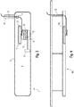
- Nachfolgend soll die Erfindung anhand der beiliegenden Zeichnung näher erläutert werden. Es zeigen:
- Figur 1
- eine seitliche schematische Schnittdarstellung einer Leuchte mit einem Kommunikationsmodul und einem erfindungsgemäß als Antenne genutzten Anschlusskabel;
- Figur 2
- eine Ansicht der Leuchte gemäß
Figur 1 von oben; - Figur 3
- eine Erweiterung der in
Figur 1 dargestellten Leuchte; und - Figur 4
- die Nutzung des erfindungsgemäßen Konzepts bei einer Stromschiene.
- Im Folgenden wird das erfindungsgemäße Konzept anhand des Beispiels einer Leuchte erläutert, in der ein Kommunikationsmodul angeordnet ist, welches in erfindungsgemäßer Weise ein Anschlusskabel für die Leuchte als Antenne nutzt. Die Leuchte wird dann weitere - in den Figuren nicht dargestellte - Komponenten wie Leuchtmittel und ein Betriebsgerät zum Betreiben der Leuchtmittel aufweisen. Da diese allerdings im Hinblick auf den Erfindungsgedanken unerheblich sind, wurde auf deren Darstellung und Erläuterung verzichtet.
- Anzumerken ist allerdings, dass die erfindungsgemäße Anordnung, wie sie in
Figur 1 gezeigt ist, in gleicher Weise auch innerhalb des Gehäuses eines so genannten Stromschieneneinkopplers vorgesehen sein könnte. Eine derartige Einheit befindet sich üblicherweise an einem Anschlusspunkt einer Stromschiene eines Lichtbandsystems und stellt die Verbindung der innerhalb des Lichtbandsystems verlaufenden Versorgungsleitungen mit einem externen Anschlusskabel her. Oftmals sind derartige Stromschieneneinkoppler, welche die Versorgung der angeschlossenen Leuchteneinheiten ermöglichen, auch für eine Kommunikation des Systems insgesamt verantwortlich, sodass die inFigur 1 gezeigte Einheit in gleicher Weise auch einen entsprechenden Stromschieneneinkoppler darstellen könnte. - Die in
Figur 1 gezeigte, mit dem Bezugszeichen 1 versehene Leuchte weist also ein Gehäuse 5 auf, welches einen Innenraum 6 umschließt, in dem die verschiedenen Komponenten der Leuchte 1 angeordnet sind. Diese - für die vorliegende Erfindung relevante - Komponenten umfassen insbesondere das inFigur 1 dargestellte Kommunikationsmodul 10 welches für eine drahtlose Kommunikation der Leuchte 1 mit weiteren Einheiten ausgebildet ist. Oftmals ist es in derartigen Situationen üblich, eine für die Abstrahlung und den Empfang der elektromagnetischen Kommunikationssignale erforderliche Antenne innerhalb des Leuchtengehäuses 5 anzuordnen. Im vorliegenden Fall wird allerdings davon ausgegangen, dass die Nutzung einer externen Antenne erforderlich ist, da beispielsweise das Gehäuse 5 derart ausgeführt ist, dass es elektromagnetische Signale entsprechend abschirmt. - Während es bislang in derartigen Fällen dann üblich war, das Kommunikationsmodul 10 mit einer außerhalb des Gehäuses 5 angeordneten separaten Antenne zu verbinden, ist gemäß dem erfindungsgemäßen Konzept nunmehr vorgesehen, das für die Stromversorgung der Leuchte 1 genutzte Anschlusskabel 20 als Antenne zu nutzen.
- Im Falle einer klassischen Einzelleuchte ist diese grundsätzlich über ein entsprechendes Anschlusskabel mit einer externen Stromversorgungsquelle verbunden. Dabei ist oftmals vorgesehen, dass eine entsprechende Anschlussklemme für das Kabel an der Außenseite des Gehäuses positioniert ist, sodass sie leicht zugänglich ist und bei der Montage der Leuchte das Stromversorgungskabel in einfacher Weise mit der Anschlussklemme verbunden werden kann.
- Im Gegensatz hierzu ist nunmehr vorgesehen, dass das Anschlusskabel 20 durch einen entsprechenden Kabelauslass 7 in einer Wand des Gehäuses 5 hindurchgeführt ist und erst innerhalb des Leuchtengehäuses 5 mit einer dort positionierten Anschlussklemme 8 verbunden ist. Das Kabel 20 besteht somit aus einem ersten, innerhalb des Gehäuses 5 verlaufenden Abschnitt 21 sowie einem außerhalb des Gehäuses 5 verlaufenden weiteren Abschnitt 22.
- Hierbei ist nunmehr vorgesehen, dass der innerhalb des Gehäuses 5 verlaufende Abschnitt 21 des Anschlusskabels 20 derart mit dem Kommunikationsmodul 10 gekoppelt ist, dass der außerhalb des Gehäuses 5 verlaufende Kabelabschnitt 22 als Antenne für die drahtlose Kommunikation genutzt werden kann. Das heißt, das Kommunikationsmodul 10 und der im Inneren des Gehäuses 5 befindliche Kabelabschnitt 21 sind derart zueinander positioniert und gekoppelt, dass das Kommunikationsmodul 10 Signale in das Kabel 20 einkoppeln bzw. aus diesem entkoppeln kann, um Daten für die drahtlose Kommunikation zu senden bzw. zu empfangen. Die Signaleinkopplung ist dabei derart, dass die Signale von dem außerhalb des Gehäuses 5 verlaufenden Kabelabschnitts 22 in Form elektromagnetischer Wellen abgestrahlt werden können, die drahtlose Signale entsprechend dem von dem Kommunikationsmodul 10 genutzten Kommunikationsstandard darstellen. In gleicher Weise ist das extern verlaufende Kabel 22 dazu geeignet, eintreffende elektromagnetische Wellen zu empfangen, die dann als Signale durch das Kabel 20 an den innerhalb des Gehäuses 5 verlaufenden Kabelabschnitts 21 derart weitergeleitet werden, dass das Kommunikationsmodul 10 die entsprechenden Signale extrahieren und weiter verarbeiten kann.
- Eine für die erfindungsgemäße Vorgehensweise geeignete Kopplung zwischen Kommunikationsmodul 10 und internem Kabelabschnitt 21 wird wie in den
Figuren 1 und 2 schematisch dargestellt dadurch erzielt, dass das Kabel 21 in definierter Weise gegenüber dem Kommunikationsmodul 10 angeordnet wird. Insbesondere kann vorgesehen sein, dass der entsprechende, für die Kopplung verantwortliche Kabelabschnitt 21 in Form einer Wicklung oder Spule 25 definiert innerhalb des Gehäuses 5 gelagert ist, sodass eine induktive Kopplung mit dem Kommunikationsmodul 10 ermöglicht wird. - Dabei kann besonderes bevorzugt vorgesehen sein, dass hierfür innerhalb des Leuchtengehäuses 5 ein entsprechend gestalteter Halter 15 genutzt wird, der einer definierten Lagerung des Kabels 21 dient. Es kann sich beispielsweise um ein aus Kunststoff bestehendes, hohlzylinderartiges Element handeln, in dessen Zentrum das Kommunikationsmodul 10 angeordnet ist. Am Außenumfang des Halters 15 ist dann das Kabel 21 mehrfach um diesen gewickelt, sodass die bereits erwähnte spulenartige Anordnung 25 erzielt wird, welche eine besonders effiziente induktive Kopplung mit dem Kommunikationsmodul 10 ermöglicht.
- Hierbei kann vorgesehen sein, dass der Halter 15 Abmessungen aufweist, die eine besonders effiziente Kopplung zwischen Kommunikationsmodul 10 und dem spulenartig aufgewickelten Kabelabschnitt 21 ermöglichen. Beispielsweise kann der Durchmesser bzw. der Querschnitt des Halters 15 einem ganzzahligen Vielfachen der für die drahtlose Kommunikation verwendeten Wellenlänge λ entsprechen bzw. einem Viertel der Wellenlänge (λ/4) oder einem Halben der Wellenlänge (λ/2). Bekanntlicherweise kann in diesem Fall dann das von dem Kommunikationsmodul 10 drahtlos abgegebene Signal sehr effizient an die spulenartige Anordnung 25 des Kabelabschnitts 21 übertragen werden, sodass eine effiziente Signalübertragung stattfindet. Das Signal ist dann entsprechend ausreichend stark, um über den außerhalb des Gehäuses 5 verlaufenden Kabelabschnitt 22 abgestrahlt werden zu können.
- Selbstverständlich besteht die Möglichkeit, die definierte Anordnung des Kabelabschnitts 21 innerhalb des Gehäuses 5 in entsprechender Weise anzupassen, wenn hierdurch die Kopplung mit dem Kommunikationsmodul 10 weiter verbessert bzw. die Antenneneigenschaften des genutzten Anschlusskabels 20 optimiert werden sollen. Dargestellt ist in
Figur 1 beispielsweise ein optional nutzbarer zusätzlicher Aufsatz 17, der in Ergänzung zu der spulenartigen Anordnung 25 des Anschlusskabelabschnitts 21 dazu genutzt werden kann, den sich daran anschließenden Abschnitt 23 des Kabels 20 derart zu lagern, dass gezielt die Antenneneigenschaften angepasst werden. Im dargestellten Beispiel wird hierbei ein Verlauf des Kabelabschnitts 23 erzielt, der einem so genannten Dipol entspricht. In gewissen Situationen kann hierdurch die Effizienz der Kommunikation weiter verbessert werden. - Auch die Anordnung des Kabelabschnitts 22 außerhalb des Gehäuses 5 sollte derart erfolgen, dass dieser in effizienter Weise als Antenne genutzt werden kann. Unter Umständen kann es hierbei von Vorteil sein, wenn auch außerhalb des Gehäuses 5 eine zusätzliche Halterung für das Kabel 20 vorgesehen ist, welches insbesondere den als Antenne genutzten Abschnitt 22 des Anschlusskabels 20 in definierter Weise hält, um dessen Antenneneigenschaften zu optimieren. Eine entsprechende Zusatzeinheit ist in
Figur 3 dargestellt und mit dem Bezugszeichen 30 versehen. - Letztendlich eröffnet also die erfindungsgemäße Lösung die Möglichkeit, ein ohnehin vorhandenes Anschlusskabel zur Stromversorgung einer Leuchte gleichzeitig auch als Antenne für eine Drahtloskommunikation zu nutzen, sodass auf die Verwendung separater zusätzlicher Komponenten für die Signalübertragung bzw. den Signalempfang verzichtet werden kann.
- Wie eingangs bereits erwähnt ist die erfindungsgemäße Lösung allerdings nicht auf einzelne Leuchten beschränkt. Wie
Figur 4 zeigt, kann das Konzept beispielsweise auch bei Versorgungseinheiten für Leuchten zum Einsatz kommen. Dargestellt ist inFigur 4 ein so genanntes Stromschienensystem 100, welches als längliches Trägerelement der Halterung und Stromversorgung einer Vielzahl einzelner Leuchteneinheiten dient. In diesem Fall sind die Leuchten dann nicht über jeweils separate Anschlusskabel mit einer externen Stromversorgung verbunden. Stattdessen verlaufen innerhalb des Stromschienensystems 100 - nicht näher dargestellte - Leitungen, welche das wahlweise Anschließen verschiedener Leuchteneinheiten ermöglichen. - Üblicherweise ist in derartigen Fällen dann an einem Anschlusspunkt des Stromschienensystems 100 eine zentrale Versorgungseinheit in Form eines so genannten Stromschieneneinkoppler 110 vorgesehen, der über ein entsprechendes Anschlusskabel 20 mit einer externen Stromversorgung verbunden ist und intern dann eine Verbindung zu den innerhalb des Systems 100 verlaufenden Stromversorgungsleitungen für die anzuschließenden Leuchteneinheiten bildet. Auch ein entsprechender Stromschieneneinkoppler 110 kann für eine drahtlose Kommunikation vorgesehen sein, um beispielsweise eine drahtlose Steuerung des Stromschienensystems 100 insgesamt zu ermöglichen oder dann entsprechende Signale auf innerhalb des Systems 100 verlaufende, zur Kommunikation genutzte Datenleitungen zu übertragen.
- In einem derartigen Fall kann wiederum das erfindungsgemäße Konzept dazu genutzt werden, das Stromversorgungskabel bzw. Anschlusskabel 20 für das Stromschienensystem als Antenne für die drahtlose Kommunikation des Stromschieneneinkopplers 110 zu nutzen. Auch in diesem Fall wird dann also ein innerhalb der Stromschiene 100 verlaufender Abschnitt des Anschlusskabels 20 für eine Kopplung mit einem entsprechenden Kommunikationsmodul genutzt werden, wobei der außerhalb des Gehäuses verlaufende Abschnitt des Anschlusskabels 20 dann die Antenne für die drahtlose Kommunikation bildet. Dabei können in gleicher Weise wie anhand der
Figuren 1 bis 3 geschildert entsprechende Halterungen innerhalb und/oder außerhalb des Gehäuses vorgesehen sein, um eine definierte Lagerung des für die Kopplung mit dem Kommunikationsmodul genutzten Abschnitts des Anschlusskabels zu ermöglichen, bzw. den extern verlaufenden Kabelabschnitt gezielt derart zu halten, dass dessen Antenneneigenschaften verbessert werden.
Claims (13)
- Leuchte (1) oder Versorgungseinheit (110) für eine Leuchte, aufweisend:• ein Gehäuse (5),• ein in dem Gehäuse (5) angeordnetes Kommunikationsmodul (10), welches für eine drahtlose Kommunikation mit einer außerhalb des Gehäuses (5) befindlichen Einheit ausgebildet ist, sowie• ein Anschlusskabel (20) zur Stromversorgung der Leuchte (5) bzw. der Versorgungseinheit (110), welches in dem Gehäuse (5) an ein Anschlusselement (8) angeschlossen und aus dem Gehäuse (5) herausgeführt ist,dadurch gekennzeichnet,
dass das Kommunikationsmodul (10) mit einem innerhalb des Gehäuses (5) verlaufenden Abschnitt (21) des Anschlusskabels (20) derart gekoppelt ist, dass ein außerhalb des Gehäuses (5) verlaufender Abschnitt (22) des Anschlusskabels (5) eine Antenne für die drahtlose Kommunikation des Kommunikationsmoduls (10) bildet. - Leuchte oder Versorgungseinheit nach Anspruch 1,
dadurch gekennzeichnet,
dass diese in dem Gehäuse (5) eine Halterung (15) zur definierten Anordnung eines Abschnitts des Anschlusskabels (20) aufweist. - Leuchte oder Versorgungseinheit nach Anspruch 2,
dadurch gekennzeichnet,
dass das Anschlusskabel (20) mehrfach um die Halterung (15) gewickelt ist, um eine spulenartige Anordnung (25) zur Kopplung mit dem Kommunikationsmodul (10) zu bilden. - Leuchte oder Versorgungseinheit nach Anspruch 2 oder 3,
dadurch gekennzeichnet,
dass die Halterung (15) einen Durchmesser bzw. eine Abmessung aufweist, welche der der Hälfte, einem Viertel oder einem ganzzahligen Vielfachen der für die Kommunikation genutzten Wellenlänge (λ) entspricht. - Leuchte oder Versorgungseinheit nach einem der Ansprüche 2 bis 4,
dadurch gekennzeichnet,
dass die Halterung (15) aus einem isolierenden Material, insbesondere aus Kunststoff besteht. - Leuchte oder Versorgungseinheit nach einem der Ansprüche 2 bis 5,
dadurch gekennzeichnet,
dass das Kommunikationsmodul (10) im Zentrum oder unterhalb der Halterung (15) angeordnet ist. - Leuchte oder Versorgungseinheit nach einem der Ansprüche 2 bis 6,
dadurch gekennzeichnet,
dass die Halterung (15) einen zusätzlichen Aufsatz (17) zur definierten Führung eines weiteren Kabelabschnitts (23) aufweist, wobei der Aufsatz (17) insbesondere eine Führung des entsprechenden Kabelabschnitts (23) in Form eines Dipols bewirkt. - Leuchte oder Versorgungseinheit nach einem der vorherigen Ansprüche,
dadurch gekennzeichnet,
dass diese außerhalb des Gehäuses (5) eine Halterung (30) zur definierten Führung des als Antenne genutzten Kabelabschnitts (22) aufweist. - Leuchte oder Versorgungseinheit nach einem der vorherigen Ansprüche,
dadurch gekennzeichnet,
dass das Anschlusskabel (20) an seinem leuchtenseitigen Ende mit einer internen Anschlussklemme (8) oder einem Betriebsgerät für eine Leuchte verbunden ist. - Leuchte oder Versorgungseinheit nach einem der vorherigen Ansprüche,
dadurch gekennzeichnet,
dass das Kommunikationsmodul (10) für eine Bluetooth-Kommunikation ausgelegt ist. - Verfahren zur drahtlosen Kommunikation eines Kommunikationsmoduls (10) einer Leuchte (1) oder einer Versorgungseinheit (110) für eine Leuchte,
wobei die Leuchte (1) oder die Versorgungseinheit (110) mit einem Anschlusskabel (20) zur Stromversorgung verbunden ist, welches in einem Gehäuse (5) der Leuchte (1) oder der Versorgungseinheit (110) an ein Anschlusselement (8) angeschlossen und aus dem Gehäuse (5) herausgeführt ist,
und wobei das Kommunikationsmodul (10) mit einem innerhalb des Gehäuses (5) verlaufenden Abschnitt (21) des Anschlusskabels (20) derart gekoppelt ist, dass es den außerhalb des Gehäuses (5) verlaufenden Abschnitt (22) des Anschlusskabels (5) als Antenne zum Senden und Empfangen von für die drahtlose Kommunikation verwendeten Signalen nutzt. - Verfahren nach Anspruch 11,
dadurch gekennzeichnet,
dass das Kommunikationsmodul (10) in den innerhalb des Gehäuses (5) verlaufenden Abschnitt (21) des Anschlusskabels (20) Signale induktiv einkoppelt bzw. induktiv Signale auskoppelt. - Verfahren nach Anspruch 11 oder 12,
dadurch gekennzeichnet,
dass die drahtlose Kommunikation entsprechend dem Bluetooth-Standard erfolgt.
Applications Claiming Priority (1)
| Application Number | Priority Date | Filing Date | Title |
|---|---|---|---|
| DE102019123021.7A DE102019123021A1 (de) | 2019-08-28 | 2019-08-28 | Leuchte oder Versorgungseinheit für Leuchten mit Kommunikationsmodul |
Publications (2)
| Publication Number | Publication Date |
|---|---|
| EP3787376A1 true EP3787376A1 (de) | 2021-03-03 |
| EP3787376B1 EP3787376B1 (de) | 2022-08-10 |
Family
ID=72243003
Family Applications (1)
| Application Number | Title | Priority Date | Filing Date |
|---|---|---|---|
| EP20192848.8A Active EP3787376B1 (de) | 2019-08-28 | 2020-08-26 | Leuchte oder versorgungseinheit für leuchten mit kommunikationsmodul |
Country Status (3)
| Country | Link |
|---|---|
| EP (1) | EP3787376B1 (de) |
| AT (1) | AT18259U1 (de) |
| DE (1) | DE102019123021A1 (de) |
Citations (8)
| Publication number | Priority date | Publication date | Assignee | Title |
|---|---|---|---|---|
| WO1983001877A1 (en) * | 1981-11-16 | 1983-05-26 | Hamlin, Inge | Radio communication system |
| DE19940651A1 (de) * | 1999-08-26 | 2001-03-08 | Deutsch Zentr Luft & Raumfahrt | Einrichtung zum Empfangen und/oder Senden von Kommunikations- und/oder Navigationssignalen |
| WO2005101919A1 (en) * | 2004-04-15 | 2005-10-27 | Koninklijke Philips Electronics N.V. | Mains wire antenna for wireless interface applications |
| DE102004057515A1 (de) * | 2004-11-29 | 2006-06-01 | Tridonicatco Gmbh & Co. Kg | Lampenbetriebsgerät mit Schnittstelleneinheit zum drahtlosen Empfangen externer Steuersignale |
| EP2309826A1 (de) * | 2009-09-26 | 2011-04-13 | WTS Kereskedelmi és Szolgáltató Kft. | Beleuchtungseinrichtung |
| WO2013109247A1 (en) * | 2012-01-17 | 2013-07-25 | Thomson Licensing | Rf remote control power cable antenna |
| WO2017067793A1 (en) * | 2015-10-22 | 2017-04-27 | Philips Lighting Holding B.V. | Lighting device having a wireless communication antenna |
| CN206834329U (zh) * | 2017-05-11 | 2018-01-02 | 四川星亚科技有限公司 | 一种应用于智能终端的小型化蓝牙天线组件 |
Family Cites Families (4)
| Publication number | Priority date | Publication date | Assignee | Title |
|---|---|---|---|---|
| BE442914A (de) * | 1940-10-04 | |||
| DE146339T1 (de) * | 1983-12-20 | 1985-11-21 | Bsh Electronics Ltd., Manchester | Trennungsvorrichtung fuer elektrisches signal mit isolierungs- und anpassungsschaltung. |
| GB2254528A (en) * | 1991-03-19 | 1992-10-07 | Axl Systems Ltd | Miners lamp communicator |
| DE29720031U1 (de) * | 1997-11-12 | 1998-01-15 | Wolfrum, Werner, 95490 Mistelgau | Sende- und Empfangsantenne zum Senden und/oder Empfangen von Signalen bestimmter Frequenz von einem Transponder |
-
2019
- 2019-08-28 DE DE102019123021.7A patent/DE102019123021A1/de not_active Withdrawn
- 2019-12-19 AT ATGM50241/2019U patent/AT18259U1/de unknown
-
2020
- 2020-08-26 EP EP20192848.8A patent/EP3787376B1/de active Active
Patent Citations (8)
| Publication number | Priority date | Publication date | Assignee | Title |
|---|---|---|---|---|
| WO1983001877A1 (en) * | 1981-11-16 | 1983-05-26 | Hamlin, Inge | Radio communication system |
| DE19940651A1 (de) * | 1999-08-26 | 2001-03-08 | Deutsch Zentr Luft & Raumfahrt | Einrichtung zum Empfangen und/oder Senden von Kommunikations- und/oder Navigationssignalen |
| WO2005101919A1 (en) * | 2004-04-15 | 2005-10-27 | Koninklijke Philips Electronics N.V. | Mains wire antenna for wireless interface applications |
| DE102004057515A1 (de) * | 2004-11-29 | 2006-06-01 | Tridonicatco Gmbh & Co. Kg | Lampenbetriebsgerät mit Schnittstelleneinheit zum drahtlosen Empfangen externer Steuersignale |
| EP2309826A1 (de) * | 2009-09-26 | 2011-04-13 | WTS Kereskedelmi és Szolgáltató Kft. | Beleuchtungseinrichtung |
| WO2013109247A1 (en) * | 2012-01-17 | 2013-07-25 | Thomson Licensing | Rf remote control power cable antenna |
| WO2017067793A1 (en) * | 2015-10-22 | 2017-04-27 | Philips Lighting Holding B.V. | Lighting device having a wireless communication antenna |
| CN206834329U (zh) * | 2017-05-11 | 2018-01-02 | 四川星亚科技有限公司 | 一种应用于智能终端的小型化蓝牙天线组件 |
Also Published As
| Publication number | Publication date |
|---|---|
| AT18259U1 (de) | 2024-07-15 |
| DE102019123021A1 (de) | 2021-03-04 |
| EP3787376B1 (de) | 2022-08-10 |
Similar Documents
| Publication | Publication Date | Title |
|---|---|---|
| EP0620565B1 (de) | Koaxiales Hochfrequenzkabel | |
| EP2333691B1 (de) | Verbindungskabel zur elektrischen oder Lichtwellenleiterverbindung zweier Systemgeräte | |
| EP2673157B1 (de) | Vorrichtung zur energieübertragung und zur induktiven kommunikation | |
| EP4006413A2 (de) | Leuchte mit hohlleiter oder richtanordnung für funksignale | |
| EP3327875A1 (de) | Elektrischer steckverbinder für ein mehradriges elektrisches kabel | |
| EP1848250A1 (de) | Leuchte | |
| EP3787376B1 (de) | Leuchte oder versorgungseinheit für leuchten mit kommunikationsmodul | |
| EP3445631B1 (de) | Vorrichtung zur daten- und/oder signalübertragung | |
| EP1693272A1 (de) | Verfahren und Antennenanordnung zur Datenübertragung zwischen Fahrzeug und Gleisbereich | |
| CH710076B1 (de) | Rahmenvorrichtung für eine Fasermanagementeinheit. | |
| DE202017103604U1 (de) | Beleuchtungseinrichtung | |
| EP4026405A1 (de) | Lichtbandsystem mit datenübertragungsfunktion | |
| EP2031626A1 (de) | Elektrische Niederspannungs-Schaltanlage | |
| EP3327869A1 (de) | Elektrischer steckverbinder für ein mehradriges elektrisches kabel | |
| EP2989696A1 (de) | Tragschiene zur bildung eines lichtbandsystems sowie lichtbandsystem | |
| EP3570203B1 (de) | Leuchte mit transponder für parametrierung und adressierung | |
| DE19935003A1 (de) | Stromversorgungs-Leitungsnetz zur Informationsübertragung | |
| EP3007291B1 (de) | Drahthalter für eine leuchte | |
| EP4257870A1 (de) | Lichtbandelement und notstromnachrüstset | |
| DE102013109685A1 (de) | RFID-Antenne für Rohrantrieb | |
| AT17212U1 (de) | Leuchte oder Betriebsgerät mit Kommunikationsmodul | |
| DE102017005742A1 (de) | Beleuchtungsvorrichtung für einen Innenraum eines Fahrzeugs | |
| DE102008025095A1 (de) | Antennendose | |
| DE102016010031A1 (de) | Elektronisches Bremssystem | |
| DE202013010013U1 (de) | Adapter für Kabelverschraubungen |
Legal Events
| Date | Code | Title | Description |
|---|---|---|---|
| PUAI | Public reference made under article 153(3) epc to a published international application that has entered the european phase |
Free format text: ORIGINAL CODE: 0009012 |
|
| STAA | Information on the status of an ep patent application or granted ep patent |
Free format text: STATUS: THE APPLICATION HAS BEEN PUBLISHED |
|
| AK | Designated contracting states |
Kind code of ref document: A1 Designated state(s): AL AT BE BG CH CY CZ DE DK EE ES FI FR GB GR HR HU IE IS IT LI LT LU LV MC MK MT NL NO PL PT RO RS SE SI SK SM TR |
|
| AX | Request for extension of the european patent |
Extension state: BA ME |
|
| STAA | Information on the status of an ep patent application or granted ep patent |
Free format text: STATUS: REQUEST FOR EXAMINATION WAS MADE |
|
| 17P | Request for examination filed |
Effective date: 20210813 |
|
| RBV | Designated contracting states (corrected) |
Designated state(s): AL AT BE BG CH CY CZ DE DK EE ES FI FR GB GR HR HU IE IS IT LI LT LU LV MC MK MT NL NO PL PT RO RS SE SI SK SM TR |
|
| RIN1 | Information on inventor provided before grant (corrected) |
Inventor name: BLOCK, STEFFEN |
|
| STAA | Information on the status of an ep patent application or granted ep patent |
Free format text: STATUS: EXAMINATION IS IN PROGRESS |
|
| 17Q | First examination report despatched |
Effective date: 20220224 |
|
| GRAP | Despatch of communication of intention to grant a patent |
Free format text: ORIGINAL CODE: EPIDOSNIGR1 |
|
| STAA | Information on the status of an ep patent application or granted ep patent |
Free format text: STATUS: GRANT OF PATENT IS INTENDED |
|
| RIC1 | Information provided on ipc code assigned before grant |
Ipc: H05B 47/19 20200101ALI20220426BHEP Ipc: H05B 45/00 20200101AFI20220426BHEP |
|
| INTG | Intention to grant announced |
Effective date: 20220513 |
|
| GRAS | Grant fee paid |
Free format text: ORIGINAL CODE: EPIDOSNIGR3 |
|
| GRAA | (expected) grant |
Free format text: ORIGINAL CODE: 0009210 |
|
| STAA | Information on the status of an ep patent application or granted ep patent |
Free format text: STATUS: THE PATENT HAS BEEN GRANTED |
|
| AK | Designated contracting states |
Kind code of ref document: B1 Designated state(s): AL AT BE BG CH CY CZ DE DK EE ES FI FR GB GR HR HU IE IS IT LI LT LU LV MC MK MT NL NO PL PT RO RS SE SI SK SM TR |
|
| REG | Reference to a national code |
Ref country code: AT Ref legal event code: REF Ref document number: 1511515 Country of ref document: AT Kind code of ref document: T Effective date: 20220815 Ref country code: CH Ref legal event code: EP |
|
| REG | Reference to a national code |
Ref country code: DE Ref legal event code: R096 Ref document number: 502020001501 Country of ref document: DE |
|
| REG | Reference to a national code |
Ref country code: IE Ref legal event code: FG4D Free format text: LANGUAGE OF EP DOCUMENT: GERMAN |
|
| REG | Reference to a national code |
Ref country code: NL Ref legal event code: MP Effective date: 20220810 |
|
| REG | Reference to a national code |
Ref country code: LT Ref legal event code: MG9D |
|
| PG25 | Lapsed in a contracting state [announced via postgrant information from national office to epo] |
Ref country code: SE Free format text: LAPSE BECAUSE OF FAILURE TO SUBMIT A TRANSLATION OF THE DESCRIPTION OR TO PAY THE FEE WITHIN THE PRESCRIBED TIME-LIMIT Effective date: 20220810 Ref country code: RS Free format text: LAPSE BECAUSE OF FAILURE TO SUBMIT A TRANSLATION OF THE DESCRIPTION OR TO PAY THE FEE WITHIN THE PRESCRIBED TIME-LIMIT Effective date: 20220810 Ref country code: PT Free format text: LAPSE BECAUSE OF FAILURE TO SUBMIT A TRANSLATION OF THE DESCRIPTION OR TO PAY THE FEE WITHIN THE PRESCRIBED TIME-LIMIT Effective date: 20221212 Ref country code: NO Free format text: LAPSE BECAUSE OF FAILURE TO SUBMIT A TRANSLATION OF THE DESCRIPTION OR TO PAY THE FEE WITHIN THE PRESCRIBED TIME-LIMIT Effective date: 20221110 Ref country code: NL Free format text: LAPSE BECAUSE OF FAILURE TO SUBMIT A TRANSLATION OF THE DESCRIPTION OR TO PAY THE FEE WITHIN THE PRESCRIBED TIME-LIMIT Effective date: 20220810 Ref country code: LV Free format text: LAPSE BECAUSE OF FAILURE TO SUBMIT A TRANSLATION OF THE DESCRIPTION OR TO PAY THE FEE WITHIN THE PRESCRIBED TIME-LIMIT Effective date: 20220810 Ref country code: LT Free format text: LAPSE BECAUSE OF FAILURE TO SUBMIT A TRANSLATION OF THE DESCRIPTION OR TO PAY THE FEE WITHIN THE PRESCRIBED TIME-LIMIT Effective date: 20220810 Ref country code: FI Free format text: LAPSE BECAUSE OF FAILURE TO SUBMIT A TRANSLATION OF THE DESCRIPTION OR TO PAY THE FEE WITHIN THE PRESCRIBED TIME-LIMIT Effective date: 20220810 |
|
| PG25 | Lapsed in a contracting state [announced via postgrant information from national office to epo] |
Ref country code: PL Free format text: LAPSE BECAUSE OF FAILURE TO SUBMIT A TRANSLATION OF THE DESCRIPTION OR TO PAY THE FEE WITHIN THE PRESCRIBED TIME-LIMIT Effective date: 20220810 Ref country code: IS Free format text: LAPSE BECAUSE OF FAILURE TO SUBMIT A TRANSLATION OF THE DESCRIPTION OR TO PAY THE FEE WITHIN THE PRESCRIBED TIME-LIMIT Effective date: 20221210 Ref country code: HR Free format text: LAPSE BECAUSE OF FAILURE TO SUBMIT A TRANSLATION OF THE DESCRIPTION OR TO PAY THE FEE WITHIN THE PRESCRIBED TIME-LIMIT Effective date: 20220810 Ref country code: GR Free format text: LAPSE BECAUSE OF FAILURE TO SUBMIT A TRANSLATION OF THE DESCRIPTION OR TO PAY THE FEE WITHIN THE PRESCRIBED TIME-LIMIT Effective date: 20221111 |
|
| PG25 | Lapsed in a contracting state [announced via postgrant information from national office to epo] |
Ref country code: SM Free format text: LAPSE BECAUSE OF FAILURE TO SUBMIT A TRANSLATION OF THE DESCRIPTION OR TO PAY THE FEE WITHIN THE PRESCRIBED TIME-LIMIT Effective date: 20220810 Ref country code: RO Free format text: LAPSE BECAUSE OF FAILURE TO SUBMIT A TRANSLATION OF THE DESCRIPTION OR TO PAY THE FEE WITHIN THE PRESCRIBED TIME-LIMIT Effective date: 20220810 Ref country code: LU Free format text: LAPSE BECAUSE OF NON-PAYMENT OF DUE FEES Effective date: 20220826 Ref country code: ES Free format text: LAPSE BECAUSE OF FAILURE TO SUBMIT A TRANSLATION OF THE DESCRIPTION OR TO PAY THE FEE WITHIN THE PRESCRIBED TIME-LIMIT Effective date: 20220810 Ref country code: DK Free format text: LAPSE BECAUSE OF FAILURE TO SUBMIT A TRANSLATION OF THE DESCRIPTION OR TO PAY THE FEE WITHIN THE PRESCRIBED TIME-LIMIT Effective date: 20220810 Ref country code: CZ Free format text: LAPSE BECAUSE OF FAILURE TO SUBMIT A TRANSLATION OF THE DESCRIPTION OR TO PAY THE FEE WITHIN THE PRESCRIBED TIME-LIMIT Effective date: 20220810 |
|
| REG | Reference to a national code |
Ref country code: BE Ref legal event code: MM Effective date: 20220831 |
|
| REG | Reference to a national code |
Ref country code: DE Ref legal event code: R097 Ref document number: 502020001501 Country of ref document: DE |
|
| PG25 | Lapsed in a contracting state [announced via postgrant information from national office to epo] |
Ref country code: SK Free format text: LAPSE BECAUSE OF FAILURE TO SUBMIT A TRANSLATION OF THE DESCRIPTION OR TO PAY THE FEE WITHIN THE PRESCRIBED TIME-LIMIT Effective date: 20220810 Ref country code: MC Free format text: LAPSE BECAUSE OF FAILURE TO SUBMIT A TRANSLATION OF THE DESCRIPTION OR TO PAY THE FEE WITHIN THE PRESCRIBED TIME-LIMIT Effective date: 20220810 Ref country code: EE Free format text: LAPSE BECAUSE OF FAILURE TO SUBMIT A TRANSLATION OF THE DESCRIPTION OR TO PAY THE FEE WITHIN THE PRESCRIBED TIME-LIMIT Effective date: 20220810 |
|
| PLBE | No opposition filed within time limit |
Free format text: ORIGINAL CODE: 0009261 |
|
| STAA | Information on the status of an ep patent application or granted ep patent |
Free format text: STATUS: NO OPPOSITION FILED WITHIN TIME LIMIT |
|
| PG25 | Lapsed in a contracting state [announced via postgrant information from national office to epo] |
Ref country code: AL Free format text: LAPSE BECAUSE OF FAILURE TO SUBMIT A TRANSLATION OF THE DESCRIPTION OR TO PAY THE FEE WITHIN THE PRESCRIBED TIME-LIMIT Effective date: 20220810 |
|
| P01 | Opt-out of the competence of the unified patent court (upc) registered |
Effective date: 20230530 |
|
| 26N | No opposition filed |
Effective date: 20230511 |
|
| PG25 | Lapsed in a contracting state [announced via postgrant information from national office to epo] |
Ref country code: IE Free format text: LAPSE BECAUSE OF NON-PAYMENT OF DUE FEES Effective date: 20220826 |
|
| PG25 | Lapsed in a contracting state [announced via postgrant information from national office to epo] |
Ref country code: SI Free format text: LAPSE BECAUSE OF FAILURE TO SUBMIT A TRANSLATION OF THE DESCRIPTION OR TO PAY THE FEE WITHIN THE PRESCRIBED TIME-LIMIT Effective date: 20220810 |
|
| PG25 | Lapsed in a contracting state [announced via postgrant information from national office to epo] |
Ref country code: BE Free format text: LAPSE BECAUSE OF NON-PAYMENT OF DUE FEES Effective date: 20220831 |
|
| REG | Reference to a national code |
Ref country code: CH Ref legal event code: PL |
|
| PG25 | Lapsed in a contracting state [announced via postgrant information from national office to epo] |
Ref country code: CY Free format text: LAPSE BECAUSE OF FAILURE TO SUBMIT A TRANSLATION OF THE DESCRIPTION OR TO PAY THE FEE WITHIN THE PRESCRIBED TIME-LIMIT Effective date: 20220810 Ref country code: CH Free format text: LAPSE BECAUSE OF NON-PAYMENT OF DUE FEES Effective date: 20230831 |
|
| PG25 | Lapsed in a contracting state [announced via postgrant information from national office to epo] |
Ref country code: MK Free format text: LAPSE BECAUSE OF FAILURE TO SUBMIT A TRANSLATION OF THE DESCRIPTION OR TO PAY THE FEE WITHIN THE PRESCRIBED TIME-LIMIT Effective date: 20220810 Ref country code: IT Free format text: LAPSE BECAUSE OF FAILURE TO SUBMIT A TRANSLATION OF THE DESCRIPTION OR TO PAY THE FEE WITHIN THE PRESCRIBED TIME-LIMIT Effective date: 20220810 Ref country code: HU Free format text: LAPSE BECAUSE OF FAILURE TO SUBMIT A TRANSLATION OF THE DESCRIPTION OR TO PAY THE FEE WITHIN THE PRESCRIBED TIME-LIMIT; INVALID AB INITIO Effective date: 20200826 |
|
| REG | Reference to a national code |
Ref country code: DE Ref legal event code: R084 Ref document number: 502020001501 Country of ref document: DE |
|
| PG25 | Lapsed in a contracting state [announced via postgrant information from national office to epo] |
Ref country code: BG Free format text: LAPSE BECAUSE OF FAILURE TO SUBMIT A TRANSLATION OF THE DESCRIPTION OR TO PAY THE FEE WITHIN THE PRESCRIBED TIME-LIMIT Effective date: 20220810 |
|
| PG25 | Lapsed in a contracting state [announced via postgrant information from national office to epo] |
Ref country code: MT Free format text: LAPSE BECAUSE OF FAILURE TO SUBMIT A TRANSLATION OF THE DESCRIPTION OR TO PAY THE FEE WITHIN THE PRESCRIBED TIME-LIMIT Effective date: 20220810 |
|
| PGFP | Annual fee paid to national office [announced via postgrant information from national office to epo] |
Ref country code: DE Payment date: 20250827 Year of fee payment: 6 |
|
| PGFP | Annual fee paid to national office [announced via postgrant information from national office to epo] |
Ref country code: GB Payment date: 20250826 Year of fee payment: 6 |
|
| PGFP | Annual fee paid to national office [announced via postgrant information from national office to epo] |
Ref country code: AT Payment date: 20251020 Year of fee payment: 5 Ref country code: FR Payment date: 20250825 Year of fee payment: 6 |
|
| PG25 | Lapsed in a contracting state [announced via postgrant information from national office to epo] |
Ref country code: TR Free format text: LAPSE BECAUSE OF FAILURE TO SUBMIT A TRANSLATION OF THE DESCRIPTION OR TO PAY THE FEE WITHIN THE PRESCRIBED TIME-LIMIT Effective date: 20220810 |