EP3785944A1 - System und verfahren zur schätzung des verschleisszustandes eines reifens unter verwendung des formfaktors der aufstandsfläche - Google Patents
System und verfahren zur schätzung des verschleisszustandes eines reifens unter verwendung des formfaktors der aufstandsfläche Download PDFInfo
- Publication number
- EP3785944A1 EP3785944A1 EP20192484.2A EP20192484A EP3785944A1 EP 3785944 A1 EP3785944 A1 EP 3785944A1 EP 20192484 A EP20192484 A EP 20192484A EP 3785944 A1 EP3785944 A1 EP 3785944A1
- Authority
- EP
- European Patent Office
- Prior art keywords
- tire
- sensor unit
- footprint
- measured
- length
- Prior art date
- Legal status (The legal status is an assumption and is not a legal conclusion. Google has not performed a legal analysis and makes no representation as to the accuracy of the status listed.)
- Granted
Links
- 238000000034 method Methods 0.000 title claims abstract description 29
- 238000010276 construction Methods 0.000 claims abstract description 35
- 238000005259 measurement Methods 0.000 claims abstract description 28
- 238000004891 communication Methods 0.000 claims abstract description 18
- 230000002596 correlated effect Effects 0.000 claims abstract description 8
- 230000005540 biological transmission Effects 0.000 claims description 14
- 238000004519 manufacturing process Methods 0.000 claims description 5
- 238000012417 linear regression Methods 0.000 claims description 4
- 239000000463 material Substances 0.000 claims description 4
- 238000013461 design Methods 0.000 claims description 3
- 238000000354 decomposition reaction Methods 0.000 claims description 2
- 238000007637 random forest analysis Methods 0.000 claims description 2
- 238000013459 approach Methods 0.000 description 8
- 230000000694 effects Effects 0.000 description 4
- 230000007423 decrease Effects 0.000 description 3
- 238000010586 diagram Methods 0.000 description 3
- 238000013528 artificial neural network Methods 0.000 description 2
- 230000001419 dependent effect Effects 0.000 description 2
- 238000012544 monitoring process Methods 0.000 description 2
- 238000012360 testing method Methods 0.000 description 2
- 238000005299 abrasion Methods 0.000 description 1
- 230000003044 adaptive effect Effects 0.000 description 1
- 239000000853 adhesive Substances 0.000 description 1
- 230000001070 adhesive effect Effects 0.000 description 1
- 238000010420 art technique Methods 0.000 description 1
- 238000004422 calculation algorithm Methods 0.000 description 1
- 150000001875 compounds Chemical class 0.000 description 1
- 230000000875 corresponding effect Effects 0.000 description 1
- 239000012530 fluid Substances 0.000 description 1
- 230000006870 function Effects 0.000 description 1
- 238000000611 regression analysis Methods 0.000 description 1
- 239000000725 suspension Substances 0.000 description 1
Images


Classifications
-
- B—PERFORMING OPERATIONS; TRANSPORTING
- B60—VEHICLES IN GENERAL
- B60C—VEHICLE TYRES; TYRE INFLATION; TYRE CHANGING; CONNECTING VALVES TO INFLATABLE ELASTIC BODIES IN GENERAL; DEVICES OR ARRANGEMENTS RELATED TO TYRES
- B60C11/00—Tyre tread bands; Tread patterns; Anti-skid inserts
- B60C11/24—Wear-indicating arrangements
- B60C11/243—Tread wear sensors, e.g. electronic sensors
-
- B—PERFORMING OPERATIONS; TRANSPORTING
- B60—VEHICLES IN GENERAL
- B60C—VEHICLE TYRES; TYRE INFLATION; TYRE CHANGING; CONNECTING VALVES TO INFLATABLE ELASTIC BODIES IN GENERAL; DEVICES OR ARRANGEMENTS RELATED TO TYRES
- B60C11/00—Tyre tread bands; Tread patterns; Anti-skid inserts
- B60C11/24—Wear-indicating arrangements
- B60C11/246—Tread wear monitoring systems
-
- B—PERFORMING OPERATIONS; TRANSPORTING
- B60—VEHICLES IN GENERAL
- B60C—VEHICLE TYRES; TYRE INFLATION; TYRE CHANGING; CONNECTING VALVES TO INFLATABLE ELASTIC BODIES IN GENERAL; DEVICES OR ARRANGEMENTS RELATED TO TYRES
- B60C19/00—Tyre parts or constructions not otherwise provided for
-
- G—PHYSICS
- G01—MEASURING; TESTING
- G01M—TESTING STATIC OR DYNAMIC BALANCE OF MACHINES OR STRUCTURES; TESTING OF STRUCTURES OR APPARATUS, NOT OTHERWISE PROVIDED FOR
- G01M17/00—Testing of vehicles
- G01M17/007—Wheeled or endless-tracked vehicles
- G01M17/02—Tyres
-
- H—ELECTRICITY
- H04—ELECTRIC COMMUNICATION TECHNIQUE
- H04L—TRANSMISSION OF DIGITAL INFORMATION, e.g. TELEGRAPHIC COMMUNICATION
- H04L12/00—Data switching networks
- H04L12/28—Data switching networks characterised by path configuration, e.g. LAN [Local Area Networks] or WAN [Wide Area Networks]
- H04L12/40—Bus networks
-
- B—PERFORMING OPERATIONS; TRANSPORTING
- B60—VEHICLES IN GENERAL
- B60C—VEHICLE TYRES; TYRE INFLATION; TYRE CHANGING; CONNECTING VALVES TO INFLATABLE ELASTIC BODIES IN GENERAL; DEVICES OR ARRANGEMENTS RELATED TO TYRES
- B60C19/00—Tyre parts or constructions not otherwise provided for
- B60C2019/004—Tyre sensors other than for detecting tyre pressure
-
- H—ELECTRICITY
- H04—ELECTRIC COMMUNICATION TECHNIQUE
- H04L—TRANSMISSION OF DIGITAL INFORMATION, e.g. TELEGRAPHIC COMMUNICATION
- H04L12/00—Data switching networks
- H04L12/28—Data switching networks characterised by path configuration, e.g. LAN [Local Area Networks] or WAN [Wide Area Networks]
- H04L12/40—Bus networks
- H04L2012/40267—Bus for use in transportation systems
- H04L2012/40273—Bus for use in transportation systems the transportation system being a vehicle
Definitions
- the invention relates generally to tire monitoring systems. More particularly, the invention relates to systems that predict tire wear. Specifically, the invention is directed to a system and method for estimating tire wear state based upon a change in the length and the shape factor of the footprint of the tire.
- Tire wear plays an important role in vehicle factors such as safety, reliability, and performance.
- Tread wear which refers to the loss of material from the tread of the tire, directly affects such vehicle factors.
- the invention relates to a system in accordance with claim 1 and to a method in accordance with claim 13.
- a tire wear state estimation system includes a vehicle and a tire that supports the vehicle.
- a first sensor unit is mounted on the tire and includes a footprint centerline length measurement sensor to measure a centerline length of a footprint of the tire.
- a second sensor unit is mounted on the tire and includes a shoulder length measurement sensor to measure a shoulder length of the footprint of the tire.
- At least one of the first sensor unit and the second sensor unit includes a pressure sensor to measure a pressure of the tire, a temperature sensor to measure a temperature of the tire, and electronic memory capacity for storing identification information for the tire.
- a processor is in electronic communication with the first sensor unit and the second sensor unit and receives the measured centerline length, the measured pressure, the measured temperature, the identification information, and the measured shoulder length.
- a tire construction database stores tire construction data and is in electronic communication with the processor. The identification information is correlated to the tire construction data.
- An analysis module is stored on the processor and receives the measured centerline length, the measured pressure, the measured temperature, the identification information, the tire construction data, and the measured shoulder length as inputs. The analysis module includes a prediction model that generates an estimated wear state for the tire from the inputs.
- a method for estimating the wear state of a tire supporting a vehicle includes the steps of mounting a first sensor unit on the tire and measuring a footprint centerline length of the tire with the sensor unit.
- a second sensor unit is mounted on the tire and a footprint shoulder length of the footprint of the tire is measured with the second sensor unit.
- a pressure of the tire and a temperature of the tire are measured with at least one of the first sensor unit and the second sensor unit, and identification information for the tire is stored in at least one of the first sensor unit and the second sensor unit.
- the measured centerline length, the measured pressure, the measured temperature, the identification information, and the measured shoulder length are received in a processor.
- Tire construction data is stored in a tire construction database that is in electronic communication with the processor, and the identification information is correlated to the tire construction data.
- An analysis module is stored on the processor, and the analysis module receives the measured centerline length, the measured pressure, the measured temperature, the identification information, the tire construction data, and the measured shoulder length as inputs.
- An estimated wear state for the tire is generated from the inputs with a prediction model in the analysis module.
- the method for estimating the wear state of a tire supporting a vehicle further comprising the steps of: providing a time filter in the analysis module; and applying the average of the values to the time filter.
- the method for estimating the wear state of a tire supporting a vehicle further comprising the steps of: providing a footprint shape calculator; calculating a footprint shape factor from the measured centerline length and the measured shoulder length with the footprint shape calculator; receiving a regularized footprint length for the tire from the footprint shape calculator; and inputting the regularized footprint length into the prediction model.
- the method for estimating the wear state of a tire supporting a vehicle further comprising the steps of: providing a vehicle-mounted collection unit to collect measurements of a speed of the vehicle and an inertia of the vehicle; receiving the speed of the vehicle and the inertia of the vehicle as inputs into the analysis module; providing an event filter in the analysis module; and comparing the speed of the vehicle and the inertia of the vehicle to threshold values with the event filter before performing further analysis with the analysis module.
- ANN artificial neural network
- ANN neural networks are non-linear statistical data modeling tools used to model complex relationships between inputs and outputs or to find patterns in data.
- Axial and “axially” means lines or directions that are parallel to the axis of rotation of the tire.
- CAN bus is an abbreviation for controller area network.
- “Circumferential” means lines or directions extending along the perimeter of the surface of the annular tread perpendicular to the axial direction.
- Equatorial centerplane means the plane perpendicular to the tire's axis of rotation and passing through the center of the tread.
- “Footprint” means the contact patch or area of contact created by the tire tread with a flat surface as the tire rotates or rolls.
- Inboard side means the side of the tire nearest the vehicle when the tire is mounted on a wheel and the wheel is mounted on the vehicle.
- “Lateral” means an axial direction.
- Outboard side means the side of the tire farthest away from the vehicle when the tire is mounted on a wheel and the wheel is mounted on the vehicle.
- Ring and radially means directions radially toward or away from the axis of rotation of the tire.
- Ring means a circumferentially extending strip of rubber on the tread which is defined by at least one circumferential groove and either a second such groove or a lateral edge, the strip being laterally undivided by full-depth grooves.
- Thread element or “traction element” means a rib or a block element defined by a shape having adjacent grooves.
- an exemplary embodiment of the tire wear state estimation system of the present invention is indicated at 10.
- the tire wear state estimation system 10 and accompanying method attempts to overcome the challenges posed by prior art methods that measure the tire wear state through direct sensor measurements.
- the subject system and method is referred herein as an "indirect" wear sensing system and method that estimates wear state.
- the prior art direct approach to measuring tire wear from tire-mounted sensors has multiple challenges, which are described above.
- the tire wear estimation state system 10 and accompanying method utilize an indirect approach and avoid the problems attendant use of tire wear sensors mounted directly to the tire tread.
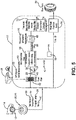
- the system 10 estimates the tread wear on each tire 12 supporting a vehicle 14. While the vehicle 14 is depicted as a passenger car, the invention is not to be so restricted. The principles of the invention find application in other vehicle categories, such as commercial trucks, in which vehicles may be supported by more or fewer tires than those shown in Figure 1 .
- the tires 12 are of conventional construction, and each tire is mounted on a respective wheel 16 as known to those skilled in the art.
- Each tire 12 includes a pair of sidewalls 18 (only one shown) that extend to a circumferential tread 20, which wears with age from road abrasion.
- An innerliner 22 is disposed on the inner surface of the tire 12, and when the tire is mounted on the wheel 16, an internal cavity 24 is formed, which is filled with a pressurized fluid, such as air.
- a first sensor unit 26 is attached to the innerliner 22 of each tire 12 by means such as an adhesive and measures certain parameters or conditions of the tire as will be described in greater detail below.
- the first sensor unit 26 is attached to the innerliner 22 at an equatorial centerplane 92 of the tire 12.
- the first sensor unit 26 may be attached to other components of the tire 12, such as on or in one of the sidewalls 18, on or in the tread 20, on the wheel 16, and/or a combination thereof.
- reference herein shall be made to mounting of the first sensor unit 26 on the tire 12, with the understanding that such mounting includes all such attachment.
- the first sensor unit 26 is mounted on each tire 12 for the purpose of detecting certain real-time tire parameters, such as tire pressure 38 ( Figure 4 ) and temperature 40. For this reason, the first sensor unit 26 preferably includes a pressure sensor and a temperature sensor and may be of any known configuration.
- the first sensor unit 26 preferably also includes electronic memory capacity for storing identification (ID) information for each tire 12, known as tire ID information and indicated at 42 ( Figure 4 ).
- tire ID information 42 may be included in another sensor unit, or in a separate tire ID storage medium, such as a tire ID tag, which is in electronic communication with the first sensor unit 26.
- the tire ID information 42 may include tire parameter and/or manufacturing information, which will be described in greater detail below.
- the first sensor unit 26 ( Figure 1 ) preferably also measures a length 28 of a centerline 30 of a footprint 32 of the tire 12. More particularly, as the tire 12 contacts the ground, the area of contact created by the tread 20 with the ground is known as the footprint 32.
- the centerline 30 of the footprint 32 corresponds to the equatorial centerplane of the tire 12, which is the plane that is perpendicular to the axis of rotation of the tire and which passes through the center of the tread 20.
- the first sensor unit 26 thus measures the length 28 of the centerline 30 of the tire footprint 32, which is referred to herein as the footprint centerline length 28.
- the first sensor unit 26 may include a strain sensor or piezoelectric sensor that measures deformation of the tread 20 and thus indicates the centerline length 28.
- the centerline length 28 decreases.
- the footprint 32 shown in Figure 2 corresponds to a tire 12 in a new condition without tire wear.
- Figure 3 shows the footprint of the same tire 12 in a worn state or condition after traveling about 21,000 kilometers (km). After such travel, the tire 12 experienced about a 30 percent (%) reduction of tread depth, as shown by the footprint after wear, indicated at 32w, and a decrease of about 6% in the centerline length, indicated by 28w, when compared to the new condition shown in Figure 2 .
- centerline length 28 a reduction of centerline length 28 corresponding to wear of the tire 12, including up to a 20% decrease in the centerline length when the tread depth was reduced by 100%, or completely reduced to a legal limit.
- the first sensor unit 26 measures the centerline length 28, 28w of the tire 12 at a certain point in time, and for the purpose of convenience, any such measurement shall be referred to as the centerline length 28.
- the pressure sensor, the temperature sensor, the tire ID capacity and/or the centerline length sensor may be incorporated into the first sensor unit 26 as a single unit, or may be incorporated into multiple units.
- reference herein shall be made to the first sensor unit 26 as a single unit.
- the first sensor unit 26 includes transmission means 34 for sending the measured parameters of tire pressure 38, tire temperature 40 and centerline length 28, as well as tire ID information 42, to a processor 36.
- the transmission means 34 may include an antenna for wireless transmission or wires for wired transmission.
- the processor 36 may be integrated into the first sensor unit 26, or may be a remote processor, which may be mounted on the vehicle 14 or be cloud-based. For the purpose of convenience, the processor 36 will be described as a remote processor mounted on the vehicle 14, with the understanding that the processor may alternatively be cloud-based or integrated into the first sensor unit 26.
- aspects of the tire wear state estimation system 10 preferably are executed on the processor 36, which enables input of data from the first sensor unit 26 and execution of specific analysis techniques and algorithms, to be described below, which are stored in a suitable storage medium and are also in electronic communication with the processor.
- the first sensor unit 26 measures the tire pressure 38, tire temperature 40 and centerline length 28, and transmits these measured parameters to the processor 36 with the tire ID information 42.
- the tire ID information 42 enables a tire construction database 44 to be electronically accessed 46.
- the tire construction database 44 stores tire construction data 50, which will be described in greater detail below.
- the database 44 is in electronic communication with the processor 36 and may be stored on the processor, enabling transmission 48 of the tire construction data 50 to the processor 36.
- the tire ID information 42 may be correlated to specific construction data 50 for each tire 12, including: the tire type; tire model; size information, such as rim size, width, and outer diameter; manufacturing location; manufacturing date; a treadcap code that includes or correlates to a compound identification; a mold code that includes or correlates to a tread structure identification; a tire footprint shape factor (FSF), a mold design drop; a tire belt/breaker angle; and an overlay material.
- the tire ID information 42 may also correlate to a service history or other information to identify specific features and parameters of each tire 12, as well as mechanical characteristics of the tire, such as cornering parameters, spring rate, load-inflation relationship, and the like.
- An analysis module 52 is stored on the processor 36, and receives the tire pressure 38, tire temperature 40, tire centerline length 28, tire ID information 42, and tire construction data 50. The analysis module 52 analyzes these inputs to generate an estimate of the tire wear state, indicated at 54, as will be described in greater detail below.
- the analysis module 52 receives the tire-based data inputs of tire pressure 38, tire temperature 40, centerline length 28 and tire ID information 42.
- the analysis module 52 preferably also receives data from a vehicle-mounted collection unit 56.
- the data from the vehicle-mounted collection unit 56 includes vehicle speed 58 as calculated from global positioning system (GPS) data, and inertial measurements 60 for the vehicle 14 from an accelerometer.
- GPS global positioning system
- An event filter 62 is applied to the data received from the vehicle-mounted collection unit 56. More particularly, vehicle conditions are reviewed in the event filter 62, including the measured vehicle speed 58 from GPS data and the inertial measurements 60. These measured values are compared to threshold values, including upper and lower limits. If the measured values are outside of the threshold values, the system 10 does not proceed, as the vehicle 14 is likely to be operating outside of normal or predictable conditions. If the measured values are within the threshold values, the measured data of tire pressure 38, tire temperature 40, centerline length 28 and vehicle speed 58 are sent to a denormalization filter 64.
- the denormalization filter 64 is employed to account for and eliminate the effect of inflation pressure 38, temperature 40 and vehicle speed 58 on the centerline length 28 of the tire 12.
- a pre-trained regression model is used to account for the effects of inflation pressure 38, temperature 40 and vehicle speed 58.
- the centerline length 28 is regressed to a pre-defined nominal condition, that is, a pre-defined inflation pressure 38, temperature 40 and vehicle speed 58.
- the denormalization filter 64 yields a normalized footprint length 66.
- the fastest wearing portion of the tire 12 may not always be at the centerline 30 ( Figure 2 ).
- the fastest wear may be at a shoulder 88.
- the difference between the wear rate of the tire 12 at the centerline 30 and at the shoulder 88 typically is dependent upon the tire construction data 50, including the tire footprint shape factor (FSF), mold design drop, tire belt/breaker angle and/or the overlay material.
- the tire construction data 50 from the tire construction database 44 thus is input into the denormalization filter 64, and is used in conjunction with the centerline length measurement 28 from the first sensor unit 26 to estimate a length 90 at the shoulder 88, which may be the fastest-wearing portion of the tread 20.
- the technique for employing the tire footprint shape factor is described in greater detail below.
- the denormalization filter 64 generates a normalized footprint length 66. Because the centerline length 28 of the tire 12 may also be affected by the vehicle load, the effect of load on the normalized footprint length 66 must be accounted for and eliminated. To eliminate the effect of load on the normalized footprint length 66, a historical footprint measurement database 68 is accessed.
- the historical footprint measurement database 68 is in electronic communication with the processor 36 and may be stored on the processor and contains a historical log of footprint measurements 70.
- the normalized footprint length 66 is correlated to the historical log 70 and an average of the values is taken.
- the average of the values is applied to a time filter 72.
- the time filter 72 accounts for time-scale decomposition of the tire 12. More particularly, the time filter 72 accounts for and eliminates bias due to factors or parameters that may affect the tire 12 over time, and which are not among the above-described measured parameters.
- the resulting value from the time filter 72 is processed by a footprint shape factor calculator 94.
- the fastest wearing portion of the tire 12 may be at a shoulder 88. This point is supported by the graphs shown in Figure 7 , in which observational data indicates that a larger percentage of tires 12 typically incur a greater degree of wear at a shoulder 88 ( Figure 2 ) rather than at the centerline 30.
- testing has shown a linear correlation between a footprint shape factor (FSF) 98 of the tire 12 and a remaining tread depth 100 of the tire, which is the tire wear state.
- FSF footprint shape factor
- the wear state estimation system 10 specifically accounts for the footprint shape factor 98 in the footprint shape factor calculator 94.
- the length 90 of the shoulder 88 may be at either an inside shoulder or an outside shoulder of the footprint 32, or it may be an average of the length at both the inside shoulder and the outside shoulder.
- the first sensor unit 26 is attached to the innerliner 22 at an equatorial centerplane 92 of the tire 12 to measure the footprint centerline length 28, as described above.
- a second sensor unit 96 is also mounted to the tire 12.
- the second sensor unit 96 is spaced laterally apart from the first sensor unit 26 and is also attached to the innerliner 22.
- the second sensor unit 96 is disposed at or near a selected one of the shoulders 88 ( Figure 2 ) to measure the shoulder length 90.
- Any suitable technique for measuring the shoulder length 90 may be employed by the second sensor unit 96.
- the second sensor unit 96 may include a strain sensor or piezoelectric sensor that measures deformation of the tread 20 and thus indicates the shoulder length 90. It is to be understood that either one or both of the first sensor unit 26 and the second sensor unit 96 may include the above-described pressor sensor, temperature sensor, and tire ID capacity.
- the first sensor unit 26 measures the footprint centerline length 28 and the second sensor unit 96 measures the footprint shoulder length 90.
- the second sensor unit includes transmission means, which may include an antenna for wireless transmission or wires for wired transmission, for sending the measured shoulder length 90 to the processor 36.
- the measurement of the centerline length 28 and the measurement of the shoulder length 90 are both electronically communicated from the respective first sensor unit 26 and the second sensor unit 96 to the analysis module 52 in the processor 36.
- the footprint shape factor calculator 94 receives these measurements, calculates the footprint shape factor 98, and yields a regularized footprint length 74 for the tire 12.
- the regularized footprint length 74 is input into a prediction model 76 to generate the estimated wear state 54 for the tire 12.
- the prediction model 76 preferably is a non-linear regression model.
- non-linear regression models are a form of regression analysis in which observational data are modeled by a function that is a nonlinear combination of the model parameters and depends on one or more independent variables. Examples of non-linear regression models that may be employed in the prediction model 76 include a Random Forest Regressor, an XgBoost Regressor, and a CatBoost Regressor.
- the tire-based measured values of centerline length 28, shoulder length 90, pressure 38 and temperature 40 are input into the analysis module 52, along with the tire ID information 42 and the vehicle-based measured values of speed 58 and inertia 60.
- the normalized footprint length 66 is generated after the denormalization filter 64 is applied, and the regularized footprint length 74 is generated after the normalized footprint length is correlated to the historical log 70, an average of the values is applied to the time filter 72, and that result is processed by the footprint shape factor calculator 94.
- the prediction model 76 employs the regularized footprint length 74 to estimate the wear state 54 of the tire 12.
- the data may be wirelessly transmitted 78 from the processor 36 on the vehicle 14 to a remote processor, such as a processor in a cloud-based server 80.
- the wear state estimation 54 may be stored and/or remotely analyzed and may also be wirelessly transmitted 82 to a display device 84 for a display that is accessible to a user of the vehicle 14, such as a smartphone.
- the wear state estimation 54 may be wirelessly transmitted 86 from the processor 36 directly to the display device 84.
- the tire wear state estimation 54 may be compared in the processor 36 to a predetermined wear limit. If the wear state estimation 54 is below the limit of acceptable remaining depth of the tread 20, a notice may be transmitted to the display device 84.
- the tire wear state estimation system 10 thus may provide notice or a recommendation to a vehicle operator that one or more tires 12 are worn and should be replaced.
- the tire wear state estimation system 10 may also transmit or communicate the tire wear state estimation 54 to a service center or a fleet manager. Moreover, the tire wear state estimation system 10 may transmit or communicate the tire wear state estimation 54 to an electronic control unit of the vehicle 14 and/or a vehicle control system, such as the braking system and/or the suspension system, to increase the performance of such systems.
- a vehicle control system such as the braking system and/or the suspension system
- the tire wear state estimation system 10 of the present invention estimates the wear state of the tire 12 by measuring the tire-based parameters of footprint centerline length 28, footprint shoulder length 90, pressure 38 and temperature 40, measuring the vehicle-based parameters of speed 58 and inertia 60, and incorporating tire ID information 42.
- the system 10 inputs these parameters and information into an analysis module 52, which provides an accurate and reliable estimation of the tire wear state 54.
- the tire wear state estimation system 10 of the present invention thus provides an independent, standalone system that does not need to be integrated into the electronic systems of the vehicle, including the CAN bus system.
- the present invention also includes a method of estimating the wear state of a tire 12.
- the method includes steps in accordance with the description that is presented above and shown in Figures 1 through 9 .
- tire wear state estimation system may be altered or rearranged, or components or steps known to those skilled in the art omitted or added, without affecting the overall concept or operation of the invention.
- electronic communication may be through a wired connection or wireless communication without affecting the overall concept or operation of the invention.
- wireless communications include radio frequency (RF) and Bluetooth® communications.
Landscapes
- Engineering & Computer Science (AREA)
- Mechanical Engineering (AREA)
- Physics & Mathematics (AREA)
- General Physics & Mathematics (AREA)
- Computer Networks & Wireless Communication (AREA)
- Signal Processing (AREA)
- Arrangements For Transmission Of Measured Signals (AREA)
- Tires In General (AREA)
Applications Claiming Priority (1)
| Application Number | Priority Date | Filing Date | Title |
|---|---|---|---|
| US201962893860P | 2019-08-30 | 2019-08-30 |
Publications (2)
| Publication Number | Publication Date |
|---|---|
| EP3785944A1 true EP3785944A1 (de) | 2021-03-03 |
| EP3785944B1 EP3785944B1 (de) | 2022-08-03 |
Family
ID=72234766
Family Applications (1)
| Application Number | Title | Priority Date | Filing Date |
|---|---|---|---|
| EP20192484.2A Active EP3785944B1 (de) | 2019-08-30 | 2020-08-24 | System und verfahren zur schätzung des verschleisszustandes eines reifens unter verwendung des formfaktors der aufstandsfläche |
Country Status (2)
| Country | Link |
|---|---|
| US (1) | US11981163B2 (de) |
| EP (1) | EP3785944B1 (de) |
Cited By (2)
| Publication number | Priority date | Publication date | Assignee | Title |
|---|---|---|---|---|
| EP4140777A1 (de) * | 2021-08-30 | 2023-03-01 | The Goodyear Tire & Rubber Company | System und verfahren zur schätzung der reifenlast |
| EP4190596A1 (de) * | 2021-12-06 | 2023-06-07 | The Goodyear Tire & Rubber Company | System und verfahren zur erkennung von unregelmässigem reifenverschleiss |
Families Citing this family (1)
| Publication number | Priority date | Publication date | Assignee | Title |
|---|---|---|---|---|
| KR20220090651A (ko) * | 2020-12-22 | 2022-06-30 | 현대자동차주식회사 | 자율 주행 제어 장치, 그를 포함하는 차량 시스템, 및 그 방법 |
Citations (3)
| Publication number | Priority date | Publication date | Assignee | Title |
|---|---|---|---|---|
| WO2014016195A1 (de) * | 2012-07-24 | 2014-01-30 | Continental Automotive Gmbh | Verfahren und vorrichtung zum schätzen einer profiltiefe eines reifens |
| DE102013220882A1 (de) * | 2013-10-15 | 2015-04-16 | Continental Automotive Gmbh | Verfahren, Steuergerät und System zum Ermitteln einer Profiltiefe eines Profils zumindest eines Reifens |
| DE102017221142A1 (de) * | 2017-11-27 | 2019-05-29 | Continental Automotive Gmbh | Verfahren, Steuereinrichtung und System zum Ermitteln einer Profiltiefe eines Profils eines Reifens |
Family Cites Families (81)
| Publication number | Priority date | Publication date | Assignee | Title |
|---|---|---|---|---|
| US5864056A (en) | 1998-02-17 | 1999-01-26 | Bell; Larry D. | Method and apparatus for monitoring the coefficient of friction between a tire and rolling surface, particularly to provide the vehicle operator with coefficient of friction, tire tread wear out and skid warning indications |
| US6083268A (en) | 1998-04-27 | 2000-07-04 | Bridgestone/Firestone, Inc. | Method for designing pneumatic tires for rolling conditions |
| EP1489532A3 (de) | 1998-09-07 | 2006-03-08 | Bridgestone Corporation | Verfahren zur Schätzung der Leistungsfähigkeit eines Reifens |
| US7267148B2 (en) | 1999-08-10 | 2007-09-11 | Michelin Recherche Et Technique S.A. | Measurement of adherence between a vehicle wheel and the roadway |
| JP4357074B2 (ja) | 2000-03-17 | 2009-11-04 | 株式会社ブリヂストン | タイヤの摩耗予測方法及びタイヤの摩耗予測装置 |
| US6532812B2 (en) | 2001-04-23 | 2003-03-18 | Ambient, Inc. | Method for improving vehicle tire tread wear |
| DE10218781A1 (de) | 2002-04-26 | 2003-11-13 | Tuev Automotive Gmbh | Auf einer Felge montierbarer Luftreifen, Sensornetz, Umdrehungsmesseinheit und Fahrzeugüberwachungssystem |
| EP1657082A4 (de) | 2003-08-19 | 2010-07-21 | Bridgestone Corp | Reifen mit eingebautem sensor und reifenzustandsbewertungsverfahren |
| US7577532B2 (en) | 2004-06-23 | 2009-08-18 | Bridgestone Corporation | Tire wear detection system and pneumatic tire |
| GB0415258D0 (en) | 2004-07-07 | 2004-08-11 | Wheelright Ltd | Vehicle tyre checking system |
| US7114383B2 (en) | 2005-01-07 | 2006-10-03 | Bridgestone Firestone North American Tire, Llc | Method and apparatus for monitoring tire performance |
| JP3853344B2 (ja) | 2005-02-23 | 2006-12-06 | 横浜ゴム株式会社 | タイヤの摩耗予測方法、タイヤの設計方法、タイヤの製造方法、タイヤの摩耗予測システム及びプログラム |
| EP2172759B1 (de) | 2007-07-11 | 2013-11-13 | Kabushiki Kaisha Bridgestone | Reifenabnutzungs-schätzverfahren |
| US7543491B2 (en) | 2007-09-19 | 2009-06-09 | Infineon Technologies Ag | Capacitive measurement of tire deformation |
| US7523656B1 (en) | 2007-11-01 | 2009-04-28 | Infineon Technologies Ag | Tire sensor system and monitoring method |
| DE102008006566A1 (de) | 2008-01-29 | 2009-07-30 | Robert Bosch Gmbh | Verfahren zur Bestimmung einer Fahrzeugreifenprofiltiefe |
| US7755367B2 (en) | 2008-06-02 | 2010-07-13 | Infineon Technologies, Ag | Silicon MEMS resonators |
| US8096172B2 (en) | 2008-06-03 | 2012-01-17 | Infineon Technologies Ag | Wireless communication apparatuses, systems and methods |
| US8483976B2 (en) | 2008-06-25 | 2013-07-09 | Kabushiki Kaisha Bridgestone | Method for estimating tire wear and apparatus for estimating tire wear |
| US7673505B2 (en) | 2008-08-01 | 2010-03-09 | Infineon Technologies Ag | Tire footprint determination apparatuses, systems and methods |
| DE102008049047A1 (de) | 2008-09-26 | 2010-04-15 | Continental Automotive Gmbh | Verfahren und Überwachungseinheit zur Überwachung eines Reifens eines Fahrzeuges |
| IT1393071B1 (it) | 2008-10-24 | 2012-04-11 | Pirelli | Metodo e sistema per il controllo dell'usura degli pneumatici di un veicolo |
| FR2937902B1 (fr) | 2008-11-06 | 2011-12-09 | Michelin Rech Tech | Pneumatique muni de temoins d'usure sonores |
| FR2940190B1 (fr) | 2008-12-23 | 2012-05-18 | Michelin Soc Tech | Procede d'alerte concernant l'usure d'un pneumatique muni d'un sillon |
| DE102009006458A1 (de) | 2009-01-28 | 2010-08-05 | Continental Automotive Gmbh | Vorrichtung und Verfahren zum Messen der Profiltiefe eines Kraftfahrzeugreifens |
| JP5261321B2 (ja) | 2009-08-25 | 2013-08-14 | 株式会社ブリヂストン | タイヤのゴムインデックス算出方法、装置、及びプログラム |
| FR2953164B1 (fr) | 2009-12-02 | 2012-01-06 | Michelin Soc Tech | Procede de detection de l'usure d'un pneumatique |
| DE102009057596A1 (de) | 2009-12-09 | 2011-06-16 | Continental Aktiengesellschaft | Vorrichtung zum Ermitteln einer Latschlänge eines Fahrzeugreifens |
| FR2954225B1 (fr) | 2009-12-18 | 2012-05-11 | Michelin Soc Tech | Pneumatique munis de temoins d'usure sonores multiniveaux |
| JP5534588B2 (ja) | 2010-02-24 | 2014-07-02 | 株式会社ブリヂストン | タイヤのゴムインデックス算出方法、装置及びプログラム |
| EP2655104B1 (de) | 2010-12-23 | 2015-02-18 | Pirelli Tyre S.p.A. | Verfahren und system zur schätzung der auf einen reifen wirkenden last |
| US10000100B2 (en) | 2010-12-30 | 2018-06-19 | Compagnie Generale Des Etablissements Michelin | Piezoelectric based system and method for determining tire load |
| US8555698B2 (en) | 2011-01-26 | 2013-10-15 | Bridgestone Americas Tire Operations, Llc | Engineered surfaces for laboratory tread wear testing of tires |
| FR2981009B1 (fr) | 2011-10-06 | 2013-12-20 | Michelin Soc Tech | Procede perfectionne de detection de l'usure d'un pneumatique |
| CN104245362B (zh) | 2012-03-29 | 2016-10-26 | 米其林企业总公司 | 充气轮胎胎面 |
| EP2734388B1 (de) | 2012-04-11 | 2016-03-23 | Huf Hülsbeck & Fürst GmbH & Co. KG | Reifenmodul mit piezoelektrischem wandler und damit ausgestatteter reifen |
| DE102012217901B3 (de) | 2012-10-01 | 2014-05-28 | Continental Automotive Gmbh | Verfahren, Steuergerät und System zum Ermitteln einer Profiltiefe eines Profils eines Reifens |
| US10024765B2 (en) | 2012-10-31 | 2018-07-17 | Compagnie Generale Des Etablissements Michelin | System and method for analyzing tire tread parameters |
| JP6227385B2 (ja) | 2013-11-21 | 2017-11-08 | Ntn株式会社 | 自動車用タイヤの摩耗量検知装置 |
| JP5806278B2 (ja) | 2013-11-26 | 2015-11-10 | 株式会社ブリヂストン | タイヤ偏摩耗推定方法及びタイヤ偏摩耗推定装置 |
| FR3014366B1 (fr) | 2013-12-05 | 2016-01-08 | Continental Automotive France | Procede de determination de l'empreinte d'un pneumatique de roue sur le sol |
| FR3020019B1 (fr) | 2014-04-18 | 2017-12-08 | Continental Automotive France | Procede et equipement de suivi d'usure de pneumatique, ainsi que systeme de suivi d'usure embarque sur vehicule |
| FR3020680B1 (fr) | 2014-05-02 | 2017-11-24 | Michelin & Cie | Systeme d'evaluation de l'etat d'un pneumatique |
| US10636227B2 (en) | 2014-06-19 | 2020-04-28 | The Goodyear Tire & Rubber Company | System and method for multiple feature detection and analysis of a rotating tire |
| JP6291366B2 (ja) | 2014-06-25 | 2018-03-14 | 住友ゴム工業株式会社 | タイヤのシミュレーション方法及びシミュレーション装置 |
| DE102014110183A1 (de) | 2014-07-18 | 2016-01-21 | Infineon Technologies Ag | Druckempfindliche Folie, Reifendruck-Sensormodul, Reifen, Verfahren und Computerprogramm zum Erhalten von auf die Deformationen eines Reifens bezogenen Informationen |
| US9921134B2 (en) | 2014-08-04 | 2018-03-20 | Dr. Ing. H.C. F. Porsche Aktiengesellschaft | System and method for determining tire wear |
| US10245906B2 (en) | 2014-11-11 | 2019-04-02 | The Goodyear Tire & Rubber Company | Tire wear compensated load estimation system and method |
| US9963146B2 (en) * | 2014-12-03 | 2018-05-08 | The Goodyear Tire & Rubber Company | Tire lift-off propensity predictive system and method |
| FR3030373B1 (fr) | 2014-12-17 | 2018-03-23 | Continental Automotive France | Procede d'estimation de la fiabilite de mesures de capteurs de roue d'un vehicule et systeme de mise en oeuvre |
| DE102014226783B4 (de) | 2014-12-22 | 2020-01-02 | Continental Automotive Gmbh | System und Verfahren zur Ermittlung wenigstens eines, eine Abmessung eines Reifenlatsches an einem Reifen eines Rades eines Fahrzeuges charakterisierenden Reifenlatschparameters |
| JP6650680B2 (ja) | 2015-03-31 | 2020-02-19 | 株式会社ブリヂストン | タイヤ摩耗量推定方法及びタイヤ摩耗量推定装置 |
| US10082381B2 (en) | 2015-04-30 | 2018-09-25 | Bebop Sensors, Inc. | Sensor systems integrated with vehicle tires |
| IN2015CH02899A (de) | 2015-06-10 | 2015-06-19 | Tymtix Technologies Pvt Ltd | |
| US9994082B2 (en) | 2015-07-31 | 2018-06-12 | Texas Instruments Deutschland, Gmbh | Tire monitoring based on inductive sensing |
| KR102626289B1 (ko) | 2015-08-14 | 2024-02-02 | 코다 이노베이션스 | 타이어 상태 또는 차량 모니터링 시스템 및 방법 |
| DE102015216210A1 (de) | 2015-08-25 | 2017-03-02 | Continental Reifen Deutschland Gmbh | Verfahren zum Bestimmen von reifencharakteristischen Einflussgrößen, sowie Steuergerät hierfür |
| DE102015216212A1 (de) | 2015-08-25 | 2017-03-02 | Continental Reifen Deutschland Gmbh | Verfahren zum Bestimmen einer Profiltiefe eines Reifenprofils, sowie Steuergerät hierfür |
| US9821611B2 (en) * | 2015-10-21 | 2017-11-21 | The Goodyear Tire & Rubber Company | Indirect tire wear state estimation system |
| US9873293B2 (en) * | 2015-10-21 | 2018-01-23 | The Goodyear Tire & Rubber Company | Indirect tire wear state prediction system and method |
| US9878721B2 (en) * | 2015-11-11 | 2018-01-30 | The Goodyear Tire & Rubber Company | Tire sensor-based robust mileage tracking system and method |
| JP2017161477A (ja) | 2016-03-11 | 2017-09-14 | 株式会社ブリヂストン | タイヤ荷重推定方法及びタイヤ荷重推定装置 |
| DE102016116698B3 (de) | 2016-09-07 | 2017-12-07 | Infineon Technologies Ag | Eine Ausfallsicherungsvorrichtung, ein Reifendruckmesssystem, ein Fahrzeug, ein Verfahren zum Überwachen und ein Computerprogramm |
| DE102016116696A1 (de) | 2016-09-07 | 2018-03-08 | Infineon Technologies Ag | Eine Vorrichtung, ein Reifendruckmesssystem, ein Reifen, ein Fahrzeug, ein Verfahren und ein Computerprogramm zum Bestimmen einer Information, die eine Länge einer Reifenaufstandsfläche eines Reifens anzeigt |
| US10809742B2 (en) | 2017-03-06 | 2020-10-20 | The Goodyear Tire & Rubber Company | System and method for tire sensor-based autonomous vehicle fleet management |
| DE102017204648A1 (de) | 2017-03-21 | 2018-09-27 | Continental Automotive Gmbh | Verfahren, Steuereinrichtung und System zum Ermitteln einer Profiltiefe eines Profils eines Reifens |
| FR3067137A1 (fr) | 2017-06-02 | 2018-12-07 | Compagnie Generale Des Etablissements Michelin | Procede de fourniture d'un service lie a l'etat et/ou au comportement d'un vehicule et/ou d'un pneumatique |
| US10603962B2 (en) | 2017-06-29 | 2020-03-31 | The Goodyear Tire & Rubber Company | Tire wear state estimation system and method |
| US11090984B2 (en) | 2017-12-20 | 2021-08-17 | The Goodyear Tire & Rubber Company | Sensor system for monitoring tire wear |
| US20190193479A1 (en) | 2017-12-20 | 2019-06-27 | The Goodyear Tire & Rubber Company | Sensor system for monitoring tire wear |
| IT201800003994A1 (it) | 2018-03-27 | 2019-09-27 | Bridgestone Europe Nv Sa | Battistrada per pneumatico e pneumatico |
| US10997708B2 (en) | 2018-04-03 | 2021-05-04 | GM Global Technology Operations LLC | Quantifying tread rib edge locations |
| US20190382034A1 (en) | 2018-06-13 | 2019-12-19 | GM Global Technology Operations LLC | Systems and methods for active tire performance monitoring |
| IT201800006322A1 (it) | 2018-06-14 | 2019-12-14 | Sistema e metodo per monitorare il consumo di battistrada | |
| US10960712B2 (en) | 2018-06-28 | 2021-03-30 | Nissan North America, Inc. | Tire wear estimation using a hybrid machine learning system and method |
| CN110733299A (zh) | 2018-07-18 | 2020-01-31 | 住友橡胶工业株式会社 | 轮胎组装体、轮胎的监控系统和方法 |
| KR102127662B1 (ko) | 2018-07-25 | 2020-06-29 | 한국타이어앤테크놀로지 주식회사 | 다점 시스템화되어 구성된 타이어용 센서 및 이를 구비한 타이어 |
| US20200047571A1 (en) | 2018-08-10 | 2020-02-13 | GM Global Technology Operations LLC | Groove wander calculations from tire-road contact details |
| US10875539B2 (en) | 2018-08-22 | 2020-12-29 | Infineon Technologies Ag | Tire load estimation |
| US10960714B2 (en) | 2018-09-26 | 2021-03-30 | The Goodyear Tire & Rubber Company | Tire with printed shear sensors |
| EP3861288A1 (de) | 2018-10-02 | 2021-08-11 | Pirelli Tyre S.p.A. | Verfahren und system zur schätzung eines restbereichs eines fahrzeugs |
-
2020
- 2020-08-20 US US16/998,380 patent/US11981163B2/en active Active
- 2020-08-24 EP EP20192484.2A patent/EP3785944B1/de active Active
Patent Citations (3)
| Publication number | Priority date | Publication date | Assignee | Title |
|---|---|---|---|---|
| WO2014016195A1 (de) * | 2012-07-24 | 2014-01-30 | Continental Automotive Gmbh | Verfahren und vorrichtung zum schätzen einer profiltiefe eines reifens |
| DE102013220882A1 (de) * | 2013-10-15 | 2015-04-16 | Continental Automotive Gmbh | Verfahren, Steuergerät und System zum Ermitteln einer Profiltiefe eines Profils zumindest eines Reifens |
| DE102017221142A1 (de) * | 2017-11-27 | 2019-05-29 | Continental Automotive Gmbh | Verfahren, Steuereinrichtung und System zum Ermitteln einer Profiltiefe eines Profils eines Reifens |
Cited By (2)
| Publication number | Priority date | Publication date | Assignee | Title |
|---|---|---|---|---|
| EP4140777A1 (de) * | 2021-08-30 | 2023-03-01 | The Goodyear Tire & Rubber Company | System und verfahren zur schätzung der reifenlast |
| EP4190596A1 (de) * | 2021-12-06 | 2023-06-07 | The Goodyear Tire & Rubber Company | System und verfahren zur erkennung von unregelmässigem reifenverschleiss |
Also Published As
| Publication number | Publication date |
|---|---|
| US11981163B2 (en) | 2024-05-14 |
| US20210061020A1 (en) | 2021-03-04 |
| EP3785944B1 (de) | 2022-08-03 |
Similar Documents
| Publication | Publication Date | Title |
|---|---|---|
| US11548324B2 (en) | Tire wear state estimation system and method employing footprint length | |
| EP3378679B1 (de) | System und verfahren zur modellbasierten reifenverschleissschätzung | |
| US9878721B2 (en) | Tire sensor-based robust mileage tracking system and method | |
| EP3785944B1 (de) | System und verfahren zur schätzung des verschleisszustandes eines reifens unter verwendung des formfaktors der aufstandsfläche | |
| EP3838628B1 (de) | Verfahren zur festsellung von reifenzuständen | |
| EP3785942B1 (de) | Verfahren zur extraktion von änderungen der reifeneigenschaften | |
| US20230173852A1 (en) | Tire irregular wear detection system and method | |
| US11644386B2 (en) | Tire wear state estimation system and method | |
| AU2020286203A1 (en) | Method of estimating tire conditions | |
| EP3960505B1 (de) | System und methode zur reifenverschleissabschätzung | |
| EP4197822A1 (de) | Reifenwechselsystem und -verfahren | |
| US11987081B2 (en) | Tire pressure monitoring system | |
| EP4385762A1 (de) | System und verfahren zur schätzung der reifenlaufflächentiefe unter verwendung der raddrehzahl | |
| EP3957501A1 (de) | System und verfahren zur vorhersage hoher reifentemperaturen | |
| EP4101659B1 (de) | System und verfahren zur reifenwechselvorhersage | |
| EP4112335A1 (de) | Reifendrucküberwachungssystem und verfahren mit achskreuzvergleich | |
| EP4385763A1 (de) | System und verfahren zur schätzung der verbleibenden reifenkilometerstand | |
| EP4140783A1 (de) | Reifendrucküberwachungssystem und -verfahren | |
| CN118182018A (zh) | 利用车轮速度估计轮胎胎面深度的系统 | |
| CN118182019A (zh) | 轮胎剩余里程估计系统 | |
| CN116278523A (zh) | 轮胎更换系统 |
Legal Events
| Date | Code | Title | Description |
|---|---|---|---|
| PUAI | Public reference made under article 153(3) epc to a published international application that has entered the european phase |
Free format text: ORIGINAL CODE: 0009012 |
|
| STAA | Information on the status of an ep patent application or granted ep patent |
Free format text: STATUS: THE APPLICATION HAS BEEN PUBLISHED |
|
| AK | Designated contracting states |
Kind code of ref document: A1 Designated state(s): AL AT BE BG CH CY CZ DE DK EE ES FI FR GB GR HR HU IE IS IT LI LT LU LV MC MK MT NL NO PL PT RO RS SE SI SK SM TR |
|
| AX | Request for extension of the european patent |
Extension state: BA ME |
|
| STAA | Information on the status of an ep patent application or granted ep patent |
Free format text: STATUS: REQUEST FOR EXAMINATION WAS MADE |
|
| 17P | Request for examination filed |
Effective date: 20210903 |
|
| RBV | Designated contracting states (corrected) |
Designated state(s): AL AT BE BG CH CY CZ DE DK EE ES FI FR GB GR HR HU IE IS IT LI LT LU LV MC MK MT NL NO PL PT RO RS SE SI SK SM TR |
|
| RIC1 | Information provided on ipc code assigned before grant |
Ipc: B60C 19/00 20060101ALN20220104BHEP Ipc: B60C 11/24 20060101AFI20220104BHEP |
|
| GRAP | Despatch of communication of intention to grant a patent |
Free format text: ORIGINAL CODE: EPIDOSNIGR1 |
|
| STAA | Information on the status of an ep patent application or granted ep patent |
Free format text: STATUS: GRANT OF PATENT IS INTENDED |
|
| INTG | Intention to grant announced |
Effective date: 20220225 |
|
| GRAS | Grant fee paid |
Free format text: ORIGINAL CODE: EPIDOSNIGR3 |
|
| GRAA | (expected) grant |
Free format text: ORIGINAL CODE: 0009210 |
|
| STAA | Information on the status of an ep patent application or granted ep patent |
Free format text: STATUS: THE PATENT HAS BEEN GRANTED |
|
| AK | Designated contracting states |
Kind code of ref document: B1 Designated state(s): AL AT BE BG CH CY CZ DE DK EE ES FI FR GB GR HR HU IE IS IT LI LT LU LV MC MK MT NL NO PL PT RO RS SE SI SK SM TR |
|
| REG | Reference to a national code |
Ref country code: AT Ref legal event code: REF Ref document number: 1508455 Country of ref document: AT Kind code of ref document: T Effective date: 20220815 Ref country code: CH Ref legal event code: EP |
|
| REG | Reference to a national code |
Ref country code: DE Ref legal event code: R096 Ref document number: 602020004318 Country of ref document: DE |
|
| REG | Reference to a national code |
Ref country code: IE Ref legal event code: FG4D |
|
| REG | Reference to a national code |
Ref country code: LT Ref legal event code: MG9D |
|
| REG | Reference to a national code |
Ref country code: NL Ref legal event code: MP Effective date: 20220803 |
|
| PG25 | Lapsed in a contracting state [announced via postgrant information from national office to epo] |
Ref country code: SE Free format text: LAPSE BECAUSE OF FAILURE TO SUBMIT A TRANSLATION OF THE DESCRIPTION OR TO PAY THE FEE WITHIN THE PRESCRIBED TIME-LIMIT Effective date: 20220803 Ref country code: RS Free format text: LAPSE BECAUSE OF FAILURE TO SUBMIT A TRANSLATION OF THE DESCRIPTION OR TO PAY THE FEE WITHIN THE PRESCRIBED TIME-LIMIT Effective date: 20220803 Ref country code: PT Free format text: LAPSE BECAUSE OF FAILURE TO SUBMIT A TRANSLATION OF THE DESCRIPTION OR TO PAY THE FEE WITHIN THE PRESCRIBED TIME-LIMIT Effective date: 20221205 Ref country code: NO Free format text: LAPSE BECAUSE OF FAILURE TO SUBMIT A TRANSLATION OF THE DESCRIPTION OR TO PAY THE FEE WITHIN THE PRESCRIBED TIME-LIMIT Effective date: 20221103 Ref country code: NL Free format text: LAPSE BECAUSE OF FAILURE TO SUBMIT A TRANSLATION OF THE DESCRIPTION OR TO PAY THE FEE WITHIN THE PRESCRIBED TIME-LIMIT Effective date: 20220803 Ref country code: LV Free format text: LAPSE BECAUSE OF FAILURE TO SUBMIT A TRANSLATION OF THE DESCRIPTION OR TO PAY THE FEE WITHIN THE PRESCRIBED TIME-LIMIT Effective date: 20220803 Ref country code: LT Free format text: LAPSE BECAUSE OF FAILURE TO SUBMIT A TRANSLATION OF THE DESCRIPTION OR TO PAY THE FEE WITHIN THE PRESCRIBED TIME-LIMIT Effective date: 20220803 Ref country code: FI Free format text: LAPSE BECAUSE OF FAILURE TO SUBMIT A TRANSLATION OF THE DESCRIPTION OR TO PAY THE FEE WITHIN THE PRESCRIBED TIME-LIMIT Effective date: 20220803 Ref country code: ES Free format text: LAPSE BECAUSE OF FAILURE TO SUBMIT A TRANSLATION OF THE DESCRIPTION OR TO PAY THE FEE WITHIN THE PRESCRIBED TIME-LIMIT Effective date: 20220803 |
|
| REG | Reference to a national code |
Ref country code: AT Ref legal event code: MK05 Ref document number: 1508455 Country of ref document: AT Kind code of ref document: T Effective date: 20220803 |
|
| PG25 | Lapsed in a contracting state [announced via postgrant information from national office to epo] |
Ref country code: PL Free format text: LAPSE BECAUSE OF FAILURE TO SUBMIT A TRANSLATION OF THE DESCRIPTION OR TO PAY THE FEE WITHIN THE PRESCRIBED TIME-LIMIT Effective date: 20220803 Ref country code: IS Free format text: LAPSE BECAUSE OF FAILURE TO SUBMIT A TRANSLATION OF THE DESCRIPTION OR TO PAY THE FEE WITHIN THE PRESCRIBED TIME-LIMIT Effective date: 20221203 Ref country code: HR Free format text: LAPSE BECAUSE OF FAILURE TO SUBMIT A TRANSLATION OF THE DESCRIPTION OR TO PAY THE FEE WITHIN THE PRESCRIBED TIME-LIMIT Effective date: 20220803 Ref country code: GR Free format text: LAPSE BECAUSE OF FAILURE TO SUBMIT A TRANSLATION OF THE DESCRIPTION OR TO PAY THE FEE WITHIN THE PRESCRIBED TIME-LIMIT Effective date: 20221104 |
|
| PG25 | Lapsed in a contracting state [announced via postgrant information from national office to epo] |
Ref country code: SM Free format text: LAPSE BECAUSE OF FAILURE TO SUBMIT A TRANSLATION OF THE DESCRIPTION OR TO PAY THE FEE WITHIN THE PRESCRIBED TIME-LIMIT Effective date: 20220803 Ref country code: RO Free format text: LAPSE BECAUSE OF FAILURE TO SUBMIT A TRANSLATION OF THE DESCRIPTION OR TO PAY THE FEE WITHIN THE PRESCRIBED TIME-LIMIT Effective date: 20220803 Ref country code: LU Free format text: LAPSE BECAUSE OF NON-PAYMENT OF DUE FEES Effective date: 20220824 Ref country code: DK Free format text: LAPSE BECAUSE OF FAILURE TO SUBMIT A TRANSLATION OF THE DESCRIPTION OR TO PAY THE FEE WITHIN THE PRESCRIBED TIME-LIMIT Effective date: 20220803 Ref country code: CZ Free format text: LAPSE BECAUSE OF FAILURE TO SUBMIT A TRANSLATION OF THE DESCRIPTION OR TO PAY THE FEE WITHIN THE PRESCRIBED TIME-LIMIT Effective date: 20220803 Ref country code: AT Free format text: LAPSE BECAUSE OF FAILURE TO SUBMIT A TRANSLATION OF THE DESCRIPTION OR TO PAY THE FEE WITHIN THE PRESCRIBED TIME-LIMIT Effective date: 20220803 |
|
| REG | Reference to a national code |
Ref country code: BE Ref legal event code: MM Effective date: 20220831 |
|
| REG | Reference to a national code |
Ref country code: DE Ref legal event code: R097 Ref document number: 602020004318 Country of ref document: DE |
|
| PG25 | Lapsed in a contracting state [announced via postgrant information from national office to epo] |
Ref country code: SK Free format text: LAPSE BECAUSE OF FAILURE TO SUBMIT A TRANSLATION OF THE DESCRIPTION OR TO PAY THE FEE WITHIN THE PRESCRIBED TIME-LIMIT Effective date: 20220803 Ref country code: MC Free format text: LAPSE BECAUSE OF FAILURE TO SUBMIT A TRANSLATION OF THE DESCRIPTION OR TO PAY THE FEE WITHIN THE PRESCRIBED TIME-LIMIT Effective date: 20220803 Ref country code: EE Free format text: LAPSE BECAUSE OF FAILURE TO SUBMIT A TRANSLATION OF THE DESCRIPTION OR TO PAY THE FEE WITHIN THE PRESCRIBED TIME-LIMIT Effective date: 20220803 |
|
| PLBE | No opposition filed within time limit |
Free format text: ORIGINAL CODE: 0009261 |
|
| STAA | Information on the status of an ep patent application or granted ep patent |
Free format text: STATUS: NO OPPOSITION FILED WITHIN TIME LIMIT |
|
| PG25 | Lapsed in a contracting state [announced via postgrant information from national office to epo] |
Ref country code: AL Free format text: LAPSE BECAUSE OF FAILURE TO SUBMIT A TRANSLATION OF THE DESCRIPTION OR TO PAY THE FEE WITHIN THE PRESCRIBED TIME-LIMIT Effective date: 20220803 |
|
| 26N | No opposition filed |
Effective date: 20230504 |
|
| PG25 | Lapsed in a contracting state [announced via postgrant information from national office to epo] |
Ref country code: IE Free format text: LAPSE BECAUSE OF NON-PAYMENT OF DUE FEES Effective date: 20220824 |
|
| PG25 | Lapsed in a contracting state [announced via postgrant information from national office to epo] |
Ref country code: SI Free format text: LAPSE BECAUSE OF FAILURE TO SUBMIT A TRANSLATION OF THE DESCRIPTION OR TO PAY THE FEE WITHIN THE PRESCRIBED TIME-LIMIT Effective date: 20220803 |
|
| PG25 | Lapsed in a contracting state [announced via postgrant information from national office to epo] |
Ref country code: BE Free format text: LAPSE BECAUSE OF NON-PAYMENT OF DUE FEES Effective date: 20220831 |
|
| REG | Reference to a national code |
Ref country code: CH Ref legal event code: PL |
|
| PG25 | Lapsed in a contracting state [announced via postgrant information from national office to epo] |
Ref country code: CY Free format text: LAPSE BECAUSE OF FAILURE TO SUBMIT A TRANSLATION OF THE DESCRIPTION OR TO PAY THE FEE WITHIN THE PRESCRIBED TIME-LIMIT Effective date: 20220803 Ref country code: CH Free format text: LAPSE BECAUSE OF NON-PAYMENT OF DUE FEES Effective date: 20230831 |
|
| PG25 | Lapsed in a contracting state [announced via postgrant information from national office to epo] |
Ref country code: MK Free format text: LAPSE BECAUSE OF FAILURE TO SUBMIT A TRANSLATION OF THE DESCRIPTION OR TO PAY THE FEE WITHIN THE PRESCRIBED TIME-LIMIT Effective date: 20220803 Ref country code: HU Free format text: LAPSE BECAUSE OF FAILURE TO SUBMIT A TRANSLATION OF THE DESCRIPTION OR TO PAY THE FEE WITHIN THE PRESCRIBED TIME-LIMIT; INVALID AB INITIO Effective date: 20200824 |
|
| PG25 | Lapsed in a contracting state [announced via postgrant information from national office to epo] |
Ref country code: TR Free format text: LAPSE BECAUSE OF FAILURE TO SUBMIT A TRANSLATION OF THE DESCRIPTION OR TO PAY THE FEE WITHIN THE PRESCRIBED TIME-LIMIT Effective date: 20220803 |
|
| PG25 | Lapsed in a contracting state [announced via postgrant information from national office to epo] |
Ref country code: BG Free format text: LAPSE BECAUSE OF FAILURE TO SUBMIT A TRANSLATION OF THE DESCRIPTION OR TO PAY THE FEE WITHIN THE PRESCRIBED TIME-LIMIT Effective date: 20220803 |
|
| PG25 | Lapsed in a contracting state [announced via postgrant information from national office to epo] |
Ref country code: MT Free format text: LAPSE BECAUSE OF FAILURE TO SUBMIT A TRANSLATION OF THE DESCRIPTION OR TO PAY THE FEE WITHIN THE PRESCRIBED TIME-LIMIT Effective date: 20220803 |
|
| PGFP | Annual fee paid to national office [announced via postgrant information from national office to epo] |
Ref country code: DE Payment date: 20240702 Year of fee payment: 5 |
|
| PGFP | Annual fee paid to national office [announced via postgrant information from national office to epo] |
Ref country code: GB Payment date: 20240701 Year of fee payment: 5 |
|
| PGFP | Annual fee paid to national office [announced via postgrant information from national office to epo] |
Ref country code: FR Payment date: 20240702 Year of fee payment: 5 |
|
| PGFP | Annual fee paid to national office [announced via postgrant information from national office to epo] |
Ref country code: IT Payment date: 20240710 Year of fee payment: 5 |