EP3785809B1 - System und verfahren zur verringerung des eindringens von luft in dichtungsrohre - Google Patents
System und verfahren zur verringerung des eindringens von luft in dichtungsrohre Download PDFInfo
- Publication number
- EP3785809B1 EP3785809B1 EP20200493.3A EP20200493A EP3785809B1 EP 3785809 B1 EP3785809 B1 EP 3785809B1 EP 20200493 A EP20200493 A EP 20200493A EP 3785809 B1 EP3785809 B1 EP 3785809B1
- Authority
- EP
- European Patent Office
- Prior art keywords
- sealant
- tube
- tube body
- opening
- gun
- Prior art date
- Legal status (The legal status is an assumption and is not a legal conclusion. Google has not performed a legal analysis and makes no representation as to the accuracy of the status listed.)
- Active
Links
Images

Classifications
-
- B—PERFORMING OPERATIONS; TRANSPORTING
- B05—SPRAYING OR ATOMISING IN GENERAL; APPLYING FLUENT MATERIALS TO SURFACES, IN GENERAL
- B05C—APPARATUS FOR APPLYING FLUENT MATERIALS TO SURFACES, IN GENERAL
- B05C17/00—Hand tools or apparatus using hand held tools, for applying liquids or other fluent materials to, for spreading applied liquids or other fluent materials on, or for partially removing applied liquids or other fluent materials from, surfaces
- B05C17/005—Hand tools or apparatus using hand held tools, for applying liquids or other fluent materials to, for spreading applied liquids or other fluent materials on, or for partially removing applied liquids or other fluent materials from, surfaces for discharging material from a reservoir or container located in or on the hand tool through an outlet orifice by pressure without using surface contacting members like pads or brushes
- B05C17/015—Hand tools or apparatus using hand held tools, for applying liquids or other fluent materials to, for spreading applied liquids or other fluent materials on, or for partially removing applied liquids or other fluent materials from, surfaces for discharging material from a reservoir or container located in or on the hand tool through an outlet orifice by pressure without using surface contacting members like pads or brushes with pneumatically or hydraulically actuated piston or the like
-
- B—PERFORMING OPERATIONS; TRANSPORTING
- B05—SPRAYING OR ATOMISING IN GENERAL; APPLYING FLUENT MATERIALS TO SURFACES, IN GENERAL
- B05C—APPARATUS FOR APPLYING FLUENT MATERIALS TO SURFACES, IN GENERAL
- B05C17/00—Hand tools or apparatus using hand held tools, for applying liquids or other fluent materials to, for spreading applied liquids or other fluent materials on, or for partially removing applied liquids or other fluent materials from, surfaces
- B05C17/005—Hand tools or apparatus using hand held tools, for applying liquids or other fluent materials to, for spreading applied liquids or other fluent materials on, or for partially removing applied liquids or other fluent materials from, surfaces for discharging material from a reservoir or container located in or on the hand tool through an outlet orifice by pressure without using surface contacting members like pads or brushes
- B05C17/00503—Details of the outlet element
- B05C17/00506—Means for connecting the outlet element to, or for disconnecting it from, the hand tool or its container
- B05C17/00513—Means for connecting the outlet element to, or for disconnecting it from, the hand tool or its container of the thread type
-
- B—PERFORMING OPERATIONS; TRANSPORTING
- B27—WORKING OR PRESERVING WOOD OR SIMILAR MATERIAL; NAILING OR STAPLING MACHINES IN GENERAL
- B27G—ACCESSORY MACHINES OR APPARATUS FOR WORKING WOOD OR SIMILAR MATERIALS; TOOLS FOR WORKING WOOD OR SIMILAR MATERIALS; SAFETY DEVICES FOR WOOD WORKING MACHINES OR TOOLS
- B27G11/00—Applying adhesives or glue to surfaces of wood to be joined
-
- B—PERFORMING OPERATIONS; TRANSPORTING
- B05—SPRAYING OR ATOMISING IN GENERAL; APPLYING FLUENT MATERIALS TO SURFACES, IN GENERAL
- B05C—APPARATUS FOR APPLYING FLUENT MATERIALS TO SURFACES, IN GENERAL
- B05C17/00—Hand tools or apparatus using hand held tools, for applying liquids or other fluent materials to, for spreading applied liquids or other fluent materials on, or for partially removing applied liquids or other fluent materials from, surfaces
- B05C17/005—Hand tools or apparatus using hand held tools, for applying liquids or other fluent materials to, for spreading applied liquids or other fluent materials on, or for partially removing applied liquids or other fluent materials from, surfaces for discharging material from a reservoir or container located in or on the hand tool through an outlet orifice by pressure without using surface contacting members like pads or brushes
- B05C17/00576—Hand tools or apparatus using hand held tools, for applying liquids or other fluent materials to, for spreading applied liquids or other fluent materials on, or for partially removing applied liquids or other fluent materials from, surfaces for discharging material from a reservoir or container located in or on the hand tool through an outlet orifice by pressure without using surface contacting members like pads or brushes characterised by the construction of a piston as pressure exerting means, or of the co-operating container
- B05C17/00579—Hand tools or apparatus using hand held tools, for applying liquids or other fluent materials to, for spreading applied liquids or other fluent materials on, or for partially removing applied liquids or other fluent materials from, surfaces for discharging material from a reservoir or container located in or on the hand tool through an outlet orifice by pressure without using surface contacting members like pads or brushes characterised by the construction of a piston as pressure exerting means, or of the co-operating container comprising means for allowing entrapped air to escape to the atmosphere
-
- B—PERFORMING OPERATIONS; TRANSPORTING
- B65—CONVEYING; PACKING; STORING; HANDLING THIN OR FILAMENTARY MATERIAL
- B65D—CONTAINERS FOR STORAGE OR TRANSPORT OF ARTICLES OR MATERIALS, e.g. BAGS, BARRELS, BOTTLES, BOXES, CANS, CARTONS, CRATES, DRUMS, JARS, TANKS, HOPPERS, FORWARDING CONTAINERS; ACCESSORIES, CLOSURES, OR FITTINGS THEREFOR; PACKAGING ELEMENTS; PACKAGES
- B65D83/00—Containers or packages with special means for dispensing contents
- B65D83/76—Containers or packages with special means for dispensing contents for dispensing fluent contents by means of a piston
- B65D83/763—Containers or packages with special means for dispensing contents for dispensing fluent contents by means of a piston the piston being actuated by a reciprocating axial motion of a shaft which engages the piston, e.g. using a ratchet mechanism
Definitions
- the sealant tube is disposed within a rigid sleeve of the sealant gun, but there is a small clearance gap between the sealant tube and the sleeve in which the sealant tube can expand.
- This allows pressurized air from the pneumatic sealant gun to seep between the plunger and an inner surface of the sealant tube, causing pockets of air to form in the sealant.
- pockets of air are eventually pushed toward the dispensing opening of the tube and are extruded out of the tube.
- the air pockets cause air bubbles or other related deformities to form in the sealant extruded from the sealant gun.
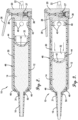
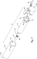
- a portion of the tube body 30 may extend outward from the hollow sleeve's second opening 26 and screw threads 31 or other attachment features may be molded into or otherwise included on an outer surface of the tube body 30 proximate to the second opening 36 thereof, such that the dispensing nozzle 16 may screw onto or otherwise attach to the tube body 30, as later described herein.
- the tube body 30 includes an engagement surface 38 proximate the first opening 34, configured to be sandwiched between the sealant gun valve body 20 and the hollow sleeve 18, creating an air-tight seal therewith.
- the engagement surface 38 is a flange extending radially outward from the tube body 30 relative to a center axis of the tube body 30.
- the dispensing nozzle 16 may be a hollow nozzle, such as a substantially cylindrical-shaped nozzle with two openings at opposing ends thereof and having a tapered portion at one of the opposing ends.
- the dispensing nozzle 16 may have screw threads 50 molded therein or other attachment features for attachment to the sealant tube 12, as later described herein.
- any dispensing nozzle may be used without departing from the scope of the invention.
- the dispensing nozzle 16 may be omitted or integrally formed into the sealant tube 12 without departing from the scope of the invention.
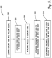
- Activation of the pneumatic sealant gun 10 may be performed by opening a portion of the sealant gun valve body 20 manually or electronically and/or turning on a pressurized air source or compressed air source.
Landscapes
- Engineering & Computer Science (AREA)
- Mechanical Engineering (AREA)
- Life Sciences & Earth Sciences (AREA)
- Wood Science & Technology (AREA)
- Forests & Forestry (AREA)
- Coating Apparatus (AREA)
- Application Of Or Painting With Fluid Materials (AREA)
- Lining Or Joining Of Plastics Or The Like (AREA)
Claims (14)
- Dichtungsrohr (12), das zur Verwendung in einer pneumatischen Dichtmittelpistole konfiguriert ist, um Dichtmittel pneumatisch aus dem Dichtungsrohr abzugeben, wobei die Dichtmittelpistole einen Ventilkörper (20) umfasst, der konfiguriert ist, um fluidisch mit einer komprimierten oder unter Druck stehenden Quelle an Gas oder Luft (22) zu koppeln, und einen Ventilsteuermechanismus (28) aufweist, der zum selektiven Blockieren oder Durchlassen des Gases oder der Luft aus dem Dichtmittelpistolenventilkörper konfiguriert ist, eine hohle Hülse (18), die eine erste Öffnung (24) und eine zweite Öffnung (26) gegenüber der ersten Öffnung aufweist, wobei die hohle Hülse mit dem Dichtmittelpistolenventilkörper über die erste Öffnung der hohlen Hülse fluidisch gekoppelt ist;
wobei das Dichtungsrohr Folgendes umfasst:einen hohlen zylindrischen Rohrkörper (30), der konfiguriert ist, um in die hohle Hülse (18) zu passen und um Dichtungsmittel (14) darin zu enthalten, wobei der Rohrkörper eine Innenfläche, eine Außenfläche gegenüber der Innenfläche, eine erste Öffnung (34), eine zweite Öffnung (36) gegenüber der ersten Öffnung und eine oder mehrere Druckentlastungsöffnungen (40), die durch den Rohrkörper gebildet sind, aufweist, die ermöglichen, dass ein Gas oder Luft zwischen dem Rohrkörper und einem Raum zwischen dem Rohrkörper und der hohlen Hülse während Verwendung der pneumatischen Dichtungsmittelpistole strömt, wodurch Druck auf der Innenfläche und der Außenfläche des Rohrkörpers ausgeglichen und Aufblasen des Rohrkörpers verhindert oder begrenzt wird, wenn er Druckluft aus der Dichtungsmittelpistole ausgesetzt ist;wobei der Rohrkörper einen Flansch (38), der sich radial nach außen davon nahe der ersten Öffnung erstreckt, wobei der Flansch (38) konfiguriert ist, um zwischen dem Ventilkörper (20) und der hohlen Hülse (18) der pneumatischen Dichtmittelpistole eingefügt zu sein, wodurch eine luftdichte Dichtung damit erzeugt wird, und einen verjüngten Abschnitt an der zweiten Öffnung beinhaltet;einen Kolben (32), der in gleitendem Kontakt mit dem Rohrkörper (30) und konfiguriert ist, um zu der zweiten Öffnung des Rohrkörpers gedrückt zu werden, wenn das Gas oder die Luft aus der pneumatischen Dichtmittelpistole abgegeben wird, wobei sich die Druckentlastungsöffnungen zwischen der ersten Öffnung des Rohrkörpers und dem Kolben befinden. - Dichtungsrohr nach Anspruch 1, wobei das Dichtungsrohr entsorgbar ist.
- Dichtungsrohr (12) nach Anspruch 1 oder 2, ferner umfassend eine Dichtung oder einen Dichtungsring (46) nahe der zweiten Öffnung (36) des Rohrkörpers (30), die/der konfiguriert ist, um eine luftdichte Dichtung zwischen der hohlen Hülse (18) und dem Rohrkörper zu bilden.
- Dichtungsrohr (12) nach Anspruch 3, wobei die Dichtung oder der Dichtungsring (46) einstückig mit dem Rohrkörper (30) ist.
- Dichtungsrohr (12) nach einem vorhergehenden Anspruch, wobei der Rohrkörper (30) aus einem halbflexiblen Material besteht.
- Dichtungsrohr (12) nach Anspruch 5, wobei der Rohrkörper (30) aus einem Kunststoffmaterial besteht.
- Dichtungsrohr (12) nach Anspruch 6, wobei der Rohrkörper (30) aus Polyethylen besteht.
- Dichtungsrohr (12) nach einem der Ansprüche 5 bis 7, wobei der Kolben (36) aus dem gleichen Material wie der Rohrkörper (30) besteht.
- Dichtungsrohr (12) nach Anspruch 1, wobei der Rohrkörper darin eingeformte Schraubgewinde (31) an der Außen- oder Innenfläche des Rohrkörpers aufweist.
- Dichtungsrohr (12) nach Anspruch 9, wobei das Dichtungsrohr (12) ferner eine Düse (16) mit Schraubgewinden (50) aufweist, die darauf zur Anbringung mit den Schraubgewinden des Rohrkörpers konfiguriert sind.
- Dichtungsrohr (12) nach einem vorhergehenden Anspruch, wobei der Kolben (32) einen Dichtungskontaktabschnitt (42), der konfiguriert ist, um Dichtmittel (14) in dem Rohr zu kontaktieren und dagegen zu drücken, und einen Rohrkontaktabschnitt (44), der konfiguriert ist, um eine Innenfläche des Rohrkörpers (30) zu kontaktieren, wenn sich der Kolben (32) durch den Rohrkörper (30) bewegt, beinhaltet.
- Dichtungsrohr (12) nach Anspruch 11, wobei sich der Rohrkontaktabschnitt (44) in einem Winkel von dem Dichtungskontaktabschnitt (42) in einer Richtung zu der ersten Öffnung (34) des Rohrkörpers (30) erstreckt.
- Dichtungsrohr (12) nach einem vorhergehenden Anspruch, wobei die eine oder mehreren Druckentlastungsöffnungen (40) ein oder mehrere Löcher, kreisförmige Öffnungen, rechteckige Öffnungen oder quadratische Öffnungen oder eine Vielzahl von Löchern umfassen.
- Dichtungsrohr (12) nach einem vorhergehenden Anspruch, umfassend mehr als eine Druckentlastungsöffnungen (40), wobei die Druckentlastungsöffnungen Löcher oder Schlitze mit einer versetzten Konfiguration umfassen.
Applications Claiming Priority (4)
| Application Number | Priority Date | Filing Date | Title |
|---|---|---|---|
| US201562264123P | 2015-12-07 | 2015-12-07 | |
| US15/292,329 US9987656B2 (en) | 2015-12-07 | 2016-10-13 | System and method for reducing air ingression into sealant tubes |
| EP16873520.7A EP3386644B1 (de) | 2015-12-07 | 2016-10-14 | System und verfahren zur verringerung von lufteindringung in dichtungsrohre |
| PCT/US2016/056961 WO2017099884A1 (en) | 2015-12-07 | 2016-10-14 | System and method for reducing air ingression into sealant tubes |
Related Parent Applications (2)
| Application Number | Title | Priority Date | Filing Date |
|---|---|---|---|
| EP16873520.7A Division EP3386644B1 (de) | 2015-12-07 | 2016-10-14 | System und verfahren zur verringerung von lufteindringung in dichtungsrohre |
| EP16873520.7A Division-Into EP3386644B1 (de) | 2015-12-07 | 2016-10-14 | System und verfahren zur verringerung von lufteindringung in dichtungsrohre |
Publications (3)
| Publication Number | Publication Date |
|---|---|
| EP3785809A1 EP3785809A1 (de) | 2021-03-03 |
| EP3785809B1 true EP3785809B1 (de) | 2024-07-10 |
| EP3785809C0 EP3785809C0 (de) | 2024-07-10 |
Family
ID=58800524
Family Applications (2)
| Application Number | Title | Priority Date | Filing Date |
|---|---|---|---|
| EP20200493.3A Active EP3785809B1 (de) | 2015-12-07 | 2016-10-14 | System und verfahren zur verringerung des eindringens von luft in dichtungsrohre |
| EP16873520.7A Active EP3386644B1 (de) | 2015-12-07 | 2016-10-14 | System und verfahren zur verringerung von lufteindringung in dichtungsrohre |
Family Applications After (1)
| Application Number | Title | Priority Date | Filing Date |
|---|---|---|---|
| EP16873520.7A Active EP3386644B1 (de) | 2015-12-07 | 2016-10-14 | System und verfahren zur verringerung von lufteindringung in dichtungsrohre |
Country Status (7)
| Country | Link |
|---|---|
| US (1) | US9987656B2 (de) |
| EP (2) | EP3785809B1 (de) |
| JP (1) | JP6775583B2 (de) |
| BR (1) | BR112018011371B1 (de) |
| CA (1) | CA3007274C (de) |
| ES (1) | ES2992535T3 (de) |
| WO (1) | WO2017099884A1 (de) |
Families Citing this family (3)
| Publication number | Priority date | Publication date | Assignee | Title |
|---|---|---|---|---|
| DE202016103241U1 (de) * | 2016-06-20 | 2017-09-21 | Marco Roth | Ummantelung zur Aufnahme und Adaption einer Kartusche an einer Ausstoßvorrichtung sowie Ausstoßvorrichtung |
| DE102018120875B4 (de) * | 2017-08-28 | 2025-05-22 | Djevair Aslani | Kartuschenpresse und deren Verwendung zur Applikation pastöser und/oder hochviskoser Massen |
| JP2020059518A (ja) * | 2018-10-09 | 2020-04-16 | 株式会社 アイセコ | チューブ絞り器 |
Family Cites Families (10)
| Publication number | Priority date | Publication date | Assignee | Title |
|---|---|---|---|---|
| GB1371662A (en) * | 1971-11-01 | 1974-10-23 | Spotnails | Pneumatically powered dispensing tool |
| US3813012A (en) * | 1973-03-12 | 1974-05-28 | Prod Res & Chem Corp | Air powered sealant dispenser, including flexible tubular conduits as valve means |
| EP0028070A1 (de) * | 1979-10-11 | 1981-05-06 | Thomas John Wood | Pistole zum Auftragen von Kittmasse |
| US7163130B2 (en) * | 2002-10-18 | 2007-01-16 | Luc Marcel Lafond | Portable gas powered fluid dispenser |
| US6892904B2 (en) * | 2003-04-22 | 2005-05-17 | Karen Osborn | Grouting gun apparatus and method |
| US7261220B2 (en) * | 2004-08-27 | 2007-08-28 | Black & Decker Inc. | Cordless DC caulk gun |
| US20100213217A1 (en) * | 2009-02-23 | 2010-08-26 | Nordson Corporation | Liquid dispensing assembly |
| EP2468414B1 (de) * | 2010-12-23 | 2015-12-23 | P C Cox Limited | Druckluftbetätigte Spender |
| JP5101743B1 (ja) * | 2012-04-02 | 2012-12-19 | 加賀ワークス株式会社 | 空圧ディスペンサ用プランジャ |
| EP3854705B1 (de) * | 2014-07-28 | 2025-09-03 | Cryovac, LLC | Verpackung |
-
2016
- 2016-10-13 US US15/292,329 patent/US9987656B2/en active Active
- 2016-10-14 CA CA3007274A patent/CA3007274C/en active Active
- 2016-10-14 JP JP2018529055A patent/JP6775583B2/ja active Active
- 2016-10-14 BR BR112018011371-9A patent/BR112018011371B1/pt not_active IP Right Cessation
- 2016-10-14 WO PCT/US2016/056961 patent/WO2017099884A1/en not_active Ceased
- 2016-10-14 EP EP20200493.3A patent/EP3785809B1/de active Active
- 2016-10-14 ES ES20200493T patent/ES2992535T3/es active Active
- 2016-10-14 EP EP16873520.7A patent/EP3386644B1/de active Active
Also Published As
| Publication number | Publication date |
|---|---|
| EP3386644B1 (de) | 2021-05-19 |
| BR112018011371A2 (pt) | 2018-12-04 |
| EP3785809C0 (de) | 2024-07-10 |
| EP3386644A4 (de) | 2019-08-07 |
| JP2018537282A (ja) | 2018-12-20 |
| US20170157639A1 (en) | 2017-06-08 |
| EP3386644A1 (de) | 2018-10-17 |
| EP3785809A1 (de) | 2021-03-03 |
| JP6775583B2 (ja) | 2020-10-28 |
| WO2017099884A1 (en) | 2017-06-15 |
| US9987656B2 (en) | 2018-06-05 |
| CA3007274A1 (en) | 2017-06-15 |
| BR112018011371B1 (pt) | 2021-12-14 |
| CA3007274C (en) | 2023-05-16 |
| ES2992535T3 (es) | 2024-12-13 |
Similar Documents
| Publication | Publication Date | Title |
|---|---|---|
| EP3785809B1 (de) | System und verfahren zur verringerung des eindringens von luft in dichtungsrohre | |
| JP5912137B2 (ja) | 内部シール付き圧縮流体分配装置 | |
| US20140367409A1 (en) | Liquid dispensing syringe and method for reducing piston bounce | |
| US9822838B2 (en) | Interference arrangement for spring | |
| JP2004532123A (ja) | 互いに同心的に配置された2つの室を備えたカートリッジのための押出装置 | |
| US9469061B2 (en) | One-piece ventable piston for a dispensing apparatus, a dispensing apparatus with same, and method of making same | |
| US20150069091A1 (en) | Plunger for pneumatic dispenser | |
| US10968031B2 (en) | Piston for a collapsible cartridge | |
| CA2657589A1 (en) | Viscous material pouring dispenser | |
| US6119903A (en) | Caulking gun and cartridge with afterflow prevention | |
| US9162275B2 (en) | Flaring device for a tubular member | |
| CN109964048A (zh) | 气动或液压机构 | |
| CN114929401A (zh) | 用于在粘性材料放置期间的改进分配控制的设备和方法 | |
| KR20130101509A (ko) | 기계적 피스 특히 기계적 프로세싱 등을 받는 피스를 위한 록킹 장치 | |
| US2717107A (en) | Gun for viscous material | |
| JP6615993B2 (ja) | ガス注入ホース | |
| US20180298889A1 (en) | Manual pump | |
| JP4902245B2 (ja) | シリンジ | |
| US20250332610A1 (en) | Applicator | |
| US20240115839A1 (en) | High pressure inflation device | |
| US814078A (en) | Pneumatic gun. | |
| EP2303470B1 (de) | Ausgabevorrichtung | |
| CN110371496A (zh) | 具有用于分配糊状或粘性材料的剂量分配器的系统 | |
| CN111263668A (zh) | 带有一次性流体主体的分配阀 |
Legal Events
| Date | Code | Title | Description |
|---|---|---|---|
| PUAI | Public reference made under article 153(3) epc to a published international application that has entered the european phase |
Free format text: ORIGINAL CODE: 0009012 |
|
| STAA | Information on the status of an ep patent application or granted ep patent |
Free format text: STATUS: THE APPLICATION HAS BEEN PUBLISHED |
|
| AC | Divisional application: reference to earlier application |
Ref document number: 3386644 Country of ref document: EP Kind code of ref document: P |
|
| AK | Designated contracting states |
Kind code of ref document: A1 Designated state(s): AL AT BE BG CH CY CZ DE DK EE ES FI FR GB GR HR HU IE IS IT LI LT LU LV MC MK MT NL NO PL PT RO RS SE SI SK SM TR |
|
| STAA | Information on the status of an ep patent application or granted ep patent |
Free format text: STATUS: REQUEST FOR EXAMINATION WAS MADE |
|
| 17P | Request for examination filed |
Effective date: 20210820 |
|
| RBV | Designated contracting states (corrected) |
Designated state(s): AL AT BE BG CH CY CZ DE DK EE ES FI FR GB GR HR HU IE IS IT LI LT LU LV MC MK MT NL NO PL PT RO RS SE SI SK SM TR |
|
| STAA | Information on the status of an ep patent application or granted ep patent |
Free format text: STATUS: EXAMINATION IS IN PROGRESS |
|
| 17Q | First examination report despatched |
Effective date: 20230316 |
|
| GRAP | Despatch of communication of intention to grant a patent |
Free format text: ORIGINAL CODE: EPIDOSNIGR1 |
|
| STAA | Information on the status of an ep patent application or granted ep patent |
Free format text: STATUS: GRANT OF PATENT IS INTENDED |
|
| INTG | Intention to grant announced |
Effective date: 20240416 |
|
| GRAS | Grant fee paid |
Free format text: ORIGINAL CODE: EPIDOSNIGR3 |
|
| GRAA | (expected) grant |
Free format text: ORIGINAL CODE: 0009210 |
|
| STAA | Information on the status of an ep patent application or granted ep patent |
Free format text: STATUS: THE PATENT HAS BEEN GRANTED |
|
| AC | Divisional application: reference to earlier application |
Ref document number: 3386644 Country of ref document: EP Kind code of ref document: P |
|
| AK | Designated contracting states |
Kind code of ref document: B1 Designated state(s): AL AT BE BG CH CY CZ DE DK EE ES FI FR GB GR HR HU IE IS IT LI LT LU LV MC MK MT NL NO PL PT RO RS SE SI SK SM TR |
|
| REG | Reference to a national code |
Ref country code: CH Ref legal event code: EP |
|
| REG | Reference to a national code |
Ref country code: DE Ref legal event code: R096 Ref document number: 602016088405 Country of ref document: DE |
|
| U01 | Request for unitary effect filed |
Effective date: 20240723 |
|
| U07 | Unitary effect registered |
Designated state(s): AT BE BG DE DK EE FI FR IT LT LU LV MT NL PT SE SI Effective date: 20240805 |
|
| U20 | Renewal fee for the european patent with unitary effect paid |
Year of fee payment: 9 Effective date: 20240925 |
|
| REG | Reference to a national code |
Ref country code: ES Ref legal event code: FG2A Ref document number: 2992535 Country of ref document: ES Kind code of ref document: T3 Effective date: 20241213 |
|
| PG25 | Lapsed in a contracting state [announced via postgrant information from national office to epo] |
Ref country code: NO Free format text: LAPSE BECAUSE OF FAILURE TO SUBMIT A TRANSLATION OF THE DESCRIPTION OR TO PAY THE FEE WITHIN THE PRESCRIBED TIME-LIMIT Effective date: 20241010 |
|
| PG25 | Lapsed in a contracting state [announced via postgrant information from national office to epo] |
Ref country code: GR Free format text: LAPSE BECAUSE OF FAILURE TO SUBMIT A TRANSLATION OF THE DESCRIPTION OR TO PAY THE FEE WITHIN THE PRESCRIBED TIME-LIMIT Effective date: 20241011 Ref country code: PL Free format text: LAPSE BECAUSE OF FAILURE TO SUBMIT A TRANSLATION OF THE DESCRIPTION OR TO PAY THE FEE WITHIN THE PRESCRIBED TIME-LIMIT Effective date: 20240710 |
|
| PG25 | Lapsed in a contracting state [announced via postgrant information from national office to epo] |
Ref country code: IS Free format text: LAPSE BECAUSE OF FAILURE TO SUBMIT A TRANSLATION OF THE DESCRIPTION OR TO PAY THE FEE WITHIN THE PRESCRIBED TIME-LIMIT Effective date: 20241110 |
|
| PG25 | Lapsed in a contracting state [announced via postgrant information from national office to epo] |
Ref country code: HR Free format text: LAPSE BECAUSE OF FAILURE TO SUBMIT A TRANSLATION OF THE DESCRIPTION OR TO PAY THE FEE WITHIN THE PRESCRIBED TIME-LIMIT Effective date: 20240710 |
|
| PG25 | Lapsed in a contracting state [announced via postgrant information from national office to epo] |
Ref country code: RS Free format text: LAPSE BECAUSE OF FAILURE TO SUBMIT A TRANSLATION OF THE DESCRIPTION OR TO PAY THE FEE WITHIN THE PRESCRIBED TIME-LIMIT Effective date: 20241010 |
|
| PGFP | Annual fee paid to national office [announced via postgrant information from national office to epo] |
Ref country code: ES Payment date: 20241111 Year of fee payment: 9 |
|
| PG25 | Lapsed in a contracting state [announced via postgrant information from national office to epo] |
Ref country code: RS Free format text: LAPSE BECAUSE OF FAILURE TO SUBMIT A TRANSLATION OF THE DESCRIPTION OR TO PAY THE FEE WITHIN THE PRESCRIBED TIME-LIMIT Effective date: 20241010 Ref country code: PL Free format text: LAPSE BECAUSE OF FAILURE TO SUBMIT A TRANSLATION OF THE DESCRIPTION OR TO PAY THE FEE WITHIN THE PRESCRIBED TIME-LIMIT Effective date: 20240710 Ref country code: NO Free format text: LAPSE BECAUSE OF FAILURE TO SUBMIT A TRANSLATION OF THE DESCRIPTION OR TO PAY THE FEE WITHIN THE PRESCRIBED TIME-LIMIT Effective date: 20241010 Ref country code: IS Free format text: LAPSE BECAUSE OF FAILURE TO SUBMIT A TRANSLATION OF THE DESCRIPTION OR TO PAY THE FEE WITHIN THE PRESCRIBED TIME-LIMIT Effective date: 20241110 Ref country code: HR Free format text: LAPSE BECAUSE OF FAILURE TO SUBMIT A TRANSLATION OF THE DESCRIPTION OR TO PAY THE FEE WITHIN THE PRESCRIBED TIME-LIMIT Effective date: 20240710 Ref country code: GR Free format text: LAPSE BECAUSE OF FAILURE TO SUBMIT A TRANSLATION OF THE DESCRIPTION OR TO PAY THE FEE WITHIN THE PRESCRIBED TIME-LIMIT Effective date: 20241011 |
|
| PG25 | Lapsed in a contracting state [announced via postgrant information from national office to epo] |
Ref country code: SM Free format text: LAPSE BECAUSE OF FAILURE TO SUBMIT A TRANSLATION OF THE DESCRIPTION OR TO PAY THE FEE WITHIN THE PRESCRIBED TIME-LIMIT Effective date: 20240710 |
|
| PG25 | Lapsed in a contracting state [announced via postgrant information from national office to epo] |
Ref country code: CZ Free format text: LAPSE BECAUSE OF FAILURE TO SUBMIT A TRANSLATION OF THE DESCRIPTION OR TO PAY THE FEE WITHIN THE PRESCRIBED TIME-LIMIT Effective date: 20240710 |
|
| PG25 | Lapsed in a contracting state [announced via postgrant information from national office to epo] |
Ref country code: SK Free format text: LAPSE BECAUSE OF FAILURE TO SUBMIT A TRANSLATION OF THE DESCRIPTION OR TO PAY THE FEE WITHIN THE PRESCRIBED TIME-LIMIT Effective date: 20240710 |
|
| PLBE | No opposition filed within time limit |
Free format text: ORIGINAL CODE: 0009261 |
|
| STAA | Information on the status of an ep patent application or granted ep patent |
Free format text: STATUS: NO OPPOSITION FILED WITHIN TIME LIMIT |
|
| REG | Reference to a national code |
Ref country code: CH Ref legal event code: PL |
|
| 26N | No opposition filed |
Effective date: 20250411 |
|
| PG25 | Lapsed in a contracting state [announced via postgrant information from national office to epo] |
Ref country code: MC Free format text: LAPSE BECAUSE OF FAILURE TO SUBMIT A TRANSLATION OF THE DESCRIPTION OR TO PAY THE FEE WITHIN THE PRESCRIBED TIME-LIMIT Effective date: 20240710 |
|
| PG25 | Lapsed in a contracting state [announced via postgrant information from national office to epo] |
Ref country code: CH Free format text: LAPSE BECAUSE OF NON-PAYMENT OF DUE FEES Effective date: 20241031 |
|
| PGFP | Annual fee paid to national office [announced via postgrant information from national office to epo] |
Ref country code: GB Payment date: 20250916 Year of fee payment: 10 |
|
| PG25 | Lapsed in a contracting state [announced via postgrant information from national office to epo] |
Ref country code: IE Free format text: LAPSE BECAUSE OF NON-PAYMENT OF DUE FEES Effective date: 20241014 |
|
| U20 | Renewal fee for the european patent with unitary effect paid |
Year of fee payment: 10 Effective date: 20250917 |
|
| PG25 | Lapsed in a contracting state [announced via postgrant information from national office to epo] |
Ref country code: RO Free format text: LAPSE BECAUSE OF FAILURE TO SUBMIT A TRANSLATION OF THE DESCRIPTION OR TO PAY THE FEE WITHIN THE PRESCRIBED TIME-LIMIT Effective date: 20240710 |