EP3785491B1 - Treiberanordnung für eine led-beleuchtungsvorrichtung, beleuchtungsvorrichtung damit und antriebsverfahren - Google Patents
Treiberanordnung für eine led-beleuchtungsvorrichtung, beleuchtungsvorrichtung damit und antriebsverfahren Download PDFInfo
- Publication number
- EP3785491B1 EP3785491B1 EP19717332.1A EP19717332A EP3785491B1 EP 3785491 B1 EP3785491 B1 EP 3785491B1 EP 19717332 A EP19717332 A EP 19717332A EP 3785491 B1 EP3785491 B1 EP 3785491B1
- Authority
- EP
- European Patent Office
- Prior art keywords
- power
- driver
- auxiliary
- light source
- led light
- Prior art date
- Legal status (The legal status is an assumption and is not a legal conclusion. Google has not performed a legal analysis and makes no representation as to the accuracy of the status listed.)
- Active
Links
Images


Classifications
-
- H—ELECTRICITY
- H05—ELECTRIC TECHNIQUES NOT OTHERWISE PROVIDED FOR
- H05B—ELECTRIC HEATING; ELECTRIC LIGHT SOURCES NOT OTHERWISE PROVIDED FOR; CIRCUIT ARRANGEMENTS FOR ELECTRIC LIGHT SOURCES, IN GENERAL
- H05B45/00—Circuit arrangements for operating light-emitting diodes [LED]
- H05B45/10—Controlling the intensity of the light
-
- H—ELECTRICITY
- H05—ELECTRIC TECHNIQUES NOT OTHERWISE PROVIDED FOR
- H05B—ELECTRIC HEATING; ELECTRIC LIGHT SOURCES NOT OTHERWISE PROVIDED FOR; CIRCUIT ARRANGEMENTS FOR ELECTRIC LIGHT SOURCES, IN GENERAL
- H05B45/00—Circuit arrangements for operating light-emitting diodes [LED]
- H05B45/30—Driver circuits
- H05B45/34—Voltage stabilisation; Maintaining constant voltage
-
- H—ELECTRICITY
- H05—ELECTRIC TECHNIQUES NOT OTHERWISE PROVIDED FOR
- H05B—ELECTRIC HEATING; ELECTRIC LIGHT SOURCES NOT OTHERWISE PROVIDED FOR; CIRCUIT ARRANGEMENTS FOR ELECTRIC LIGHT SOURCES, IN GENERAL
- H05B45/00—Circuit arrangements for operating light-emitting diodes [LED]
- H05B45/30—Driver circuits
- H05B45/357—Driver circuits specially adapted for retrofit LED light sources
-
- H—ELECTRICITY
- H05—ELECTRIC TECHNIQUES NOT OTHERWISE PROVIDED FOR
- H05B—ELECTRIC HEATING; ELECTRIC LIGHT SOURCES NOT OTHERWISE PROVIDED FOR; CIRCUIT ARRANGEMENTS FOR ELECTRIC LIGHT SOURCES, IN GENERAL
- H05B45/00—Circuit arrangements for operating light-emitting diodes [LED]
- H05B45/30—Driver circuits
- H05B45/37—Converter circuits
- H05B45/3725—Switched mode power supply [SMPS]
-
- H—ELECTRICITY
- H05—ELECTRIC TECHNIQUES NOT OTHERWISE PROVIDED FOR
- H05B—ELECTRIC HEATING; ELECTRIC LIGHT SOURCES NOT OTHERWISE PROVIDED FOR; CIRCUIT ARRANGEMENTS FOR ELECTRIC LIGHT SOURCES, IN GENERAL
- H05B47/00—Circuit arrangements for operating light sources in general, i.e. where the type of light source is not relevant
- H05B47/10—Controlling the light source
- H05B47/105—Controlling the light source in response to determined parameters
- H05B47/11—Controlling the light source in response to determined parameters by determining the brightness or colour temperature of ambient light
-
- H—ELECTRICITY
- H05—ELECTRIC TECHNIQUES NOT OTHERWISE PROVIDED FOR
- H05B—ELECTRIC HEATING; ELECTRIC LIGHT SOURCES NOT OTHERWISE PROVIDED FOR; CIRCUIT ARRANGEMENTS FOR ELECTRIC LIGHT SOURCES, IN GENERAL
- H05B45/00—Circuit arrangements for operating light-emitting diodes [LED]
- H05B45/30—Driver circuits
- H05B45/37—Converter circuits
- H05B45/3725—Switched mode power supply [SMPS]
- H05B45/375—Switched mode power supply [SMPS] using buck topology
-
- H—ELECTRICITY
- H05—ELECTRIC TECHNIQUES NOT OTHERWISE PROVIDED FOR
- H05B—ELECTRIC HEATING; ELECTRIC LIGHT SOURCES NOT OTHERWISE PROVIDED FOR; CIRCUIT ARRANGEMENTS FOR ELECTRIC LIGHT SOURCES, IN GENERAL
- H05B45/00—Circuit arrangements for operating light-emitting diodes [LED]
- H05B45/30—Driver circuits
- H05B45/37—Converter circuits
- H05B45/3725—Switched mode power supply [SMPS]
- H05B45/38—Switched mode power supply [SMPS] using boost topology
-
- H—ELECTRICITY
- H05—ELECTRIC TECHNIQUES NOT OTHERWISE PROVIDED FOR
- H05B—ELECTRIC HEATING; ELECTRIC LIGHT SOURCES NOT OTHERWISE PROVIDED FOR; CIRCUIT ARRANGEMENTS FOR ELECTRIC LIGHT SOURCES, IN GENERAL
- H05B45/00—Circuit arrangements for operating light-emitting diodes [LED]
- H05B45/30—Driver circuits
- H05B45/37—Converter circuits
- H05B45/3725—Switched mode power supply [SMPS]
- H05B45/385—Switched mode power supply [SMPS] using flyback topology
-
- H—ELECTRICITY
- H05—ELECTRIC TECHNIQUES NOT OTHERWISE PROVIDED FOR
- H05B—ELECTRIC HEATING; ELECTRIC LIGHT SOURCES NOT OTHERWISE PROVIDED FOR; CIRCUIT ARRANGEMENTS FOR ELECTRIC LIGHT SOURCES, IN GENERAL
- H05B47/00—Circuit arrangements for operating light sources in general, i.e. where the type of light source is not relevant
- H05B47/10—Controlling the light source
- H05B47/175—Controlling the light source by remote control
- H05B47/19—Controlling the light source by remote control via wireless transmission
Definitions
- This invention relates to LED lighting systems and drivers, and relates in particular to lighting systems in which additional functionality is integrated into the luminaires of the lighting system, for example for sensing or communication purposes.
- a power supply is needed which generates multiple outputs.
- An auxiliary supply is needed, in addition to the main supply for the lighting load, for supplying master control units, logic circuits, gate drivers sensors and/or communications modules etc.
- a standalone auxiliary power supply is widely adopted in an LED driver. There is then a standby power supply separate to the main LED driver, which functions as the power supply for the lighting load.
- a dimming function is a common feature provided by a LED driver.
- the efficiency is very important in order to provide energy savings.
- the LED driver must be designed according to the maximum power requirements, so large current rating components are used in the design which means the high -efficiency region is at the average to high power/load and the efficiency of LED driver at a light load is low.
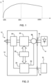
- the typical efficiency is as shown in Figure 1 , which plots the efficiency (E, y-axis) versus the loading as a percentage of the rated load. There is a particular efficiency issue at low load conditions.
- WO2015128388A1 discloses a two-driver architecture wherein a switched mode power supply's input current can be regulated according to whether a capacitor of a linear driver is being charged at the peak of the mains, so as to provide good power factor and less flicker, meanwhile obtain a homogenous light output.
- WO2015185570A1 discloses an emergency lamp with a LED driver to power the LED, and a DC-DC converter to power the LED from a battery when there is emergency, power cut on the supply.
- US9826583B1 discloses an auxiliary power supply, in an LED driver, that powers an external controller which is for controlling a controller in the LED driver.
- auxiliary driver to deliver power to a LED lighting load, instead of a main LED driver, when the LED power demand is sufficiently low that it can be met by the auxiliary driver.
- the auxiliary driver is generally still a low power driver when supplied by the AC mains and is originally only intended for auxiliary modules, such as sensors and communications circuits, and has a power delivery capability which is lower than the peak power demand of the LED lighting load.
- a driver arrangement for a LED lighting device with a LED light source and at least one additional auxiliary module comprising:
- the controller for example controls the delivery of power from the auxiliary driver to the auxiliary power output or to both the main power output and the auxiliary power output.
- This driver arrangement has separate drivers for an LED lighting device and for one or more auxiliary modules. In this way, each driver can be optimized for the load it is required to drive. This means that the device may be more efficient in a low power lighting mode, by using a driver suited for such low power operation.
- the output of the auxiliary driver is able to be used to power the LED light source. This may for example be appropriate when the power demand of the LED light source is low, for example during periods of deep dimming. By using the auxiliary driver for this time, the overall efficiency of the driver arrangement may be improved.
- the auxiliary driver may be used to deliver the required power more efficiently that the main LED driver.
- the command connection is different from the AC mains
- the main LED driver and the auxiliary driver are both adapted to power the LED from the AC mains
- the rate maximum power of the auxiliary driver is lower than the rate maximum power of the main LED driver
- the auxiliary driver has a high efficiency than that of the main LED driver at the set output power lower than the threshold value.
- the command connection is a wireless connection.
- the controller may comprise a power control loop comprising a sensor for sensing a power delivery to the LED light source from the auxiliary driver and to control a power delivery to the LED light source from the main driver accordingly.
- the power control loop is for the main LED driver and comprises a sensor for sensing a power delivery to the LED light source from the auxiliary driver or from both of the main LED driver and the auxiliary driver.
- the power control loop is adapted to control a power delivery to the LED light source from the main power conversion circuit such that the power delivery to the LED light source matches an output power demand of the LED light source.
- the controller is adapted to control the delivery of power in dependence on the power demand of the LED light source and of the at least one additional auxiliary module.
- auxiliary driver either for the auxiliary module (or modules) or additionally for the LED light source thus takes account of both power demands. If both can be met by the auxiliary driver, then it will be used as the sole power supply. If both cannot be met by the auxiliary driver, then the auxiliary driver should not be overloaded and preferably the two drivers will both be used.
- the controller is for example adapted to retrieve the power demand of the at least one additional auxiliary module by:
- the controller may be adapted to set the power output of the auxiliary driver to be the smaller of:
- the output power of the auxiliary driver is set to a sum of the power demand of the at least one additional auxiliary module and the output power demand of the LED light source. If this sum exceeds the peak power output capability of the auxiliary driver, then it is set to the peak power. This means that the auxiliary driver alone is used whenever possible. Whenever the total power demand cannot be met only by the auxiliary driver, then the auxiliary driver is driven to its full power, and the surplus additional power requirement is delivered by the main LED driver. This means the efficiency is improved, because the auxiliary driver is always responsible for the lowest tranche of power demand.
- the auxiliary driver for example comprises a constant voltage driver for the additional modules.
- the additional modules for example then comprise input/output power control capability so that they can function properly from a constant voltage power supply.
- the controller is adapted to maintain a peak current corresponding to the peak output power of the auxiliary driver, meanwhile regulating the voltage on the auxiliary power output.
- the controller is adapted to maintain a current corresponding to the output power demand of the LED light source meanwhile regulating the voltage on the auxiliary power output.
- This preferred embodiment defines the feedback control loop for the auxiliary driver.
- the auxiliary driver may comprise a main power inductor and a first secondary inductor magnetically coupled to the main power inductor and adapted to connect to the at least one additional auxiliary module. This provides an isolated supply to the auxiliary module. Further, there may be a second secondary inductor for providing a second isolated supply to a different type of auxiliary module.
- the two secondary inductors may give rise to different transformer ratios so that the outputs voltage can be different and are adapted to the different types of auxiliary loads to be supplied, such as 5V loads and 12V loads etc..
- the main power inductor is for example adapted to connect to the LED light source, in an electrically direct manner.
- the auxiliary driver comprises a further secondary inductor magnetically coupled to the main power inductor and adapted to connect to the LED light source. This means that both supplies are isolated.
- This provides a lighting device which incorporates the driver arrangement described above.
- the at least one additional auxiliary module may comprise:
- auxiliary modules There may be a single module or multiple modules. They are used to form a network of devices. Typically, the modules add functionality to the light system, such as based on presence detection, ambient light sensing etc. However, the modules may be provided for other purposes, for example as part of an intruder detection system, or sensors for controlling a heating, ventilation and air conditioning system (HVAC).
- HVAC heating, ventilation and air conditioning system
- the invention also provides a method of controlling the supply of power from a driver arrangement to a LED lighting device with a LED light source and to at least one additional auxiliary module, the method comprising:
- the selective control of power delivery enables efficiency improvements to be obtained, by avoiding operating a high power driver at very low power demand levels.
- a power delivery to the LED light source from the auxiliary driver may be sensed so that a power delivery to the LED light source is then controlled from the main LED driver accordingly.
- Selectively controlling the delivery of power is for example in dependence on the power demand of the LED light source and of the at least one additional auxiliary module.
- the method may comprise setting the power output of the auxiliary driver to be the smaller of:
- the auxiliary driver is used preferentially for low power demands.
- the invention provides a driver arrangement for a LED lighting device, in which the lighting device has a LED light source and at least one additional auxiliary module.
- the driver arrangement comprises separate main and auxiliary drivers.
- the delivery of power from the auxiliary driver is controlled to either an auxiliary power output or to both a main power output and the auxiliary power output.
- Each driver can be optimized for the load it is required to drive.
- the device may overall be more efficient in a low power mode, by using a driver suited for such low power operation.
- the auxiliary driver may be used.
- Figure 2 shows a driver arrangement 10 for a LED lighting device 12 with a LED light source 14 and at least one additional auxiliary module 16.
- the lighting device is defined as the overall system, including the light source, the driver arrangement and the auxiliary modules.
- the driver arrangement 10 has a main power output 18 for providing power to the LED light source 14.
- a main LED driver 20 is connected to the main power output 18. It comprises a switch mode power supply, having a main power conversion circuit. Alternatively the main LED driver could also be a linear power supply or other type of power supply instead of the switch mode power supply.
- An auxiliary power output 22 is provided for providing power to the at least one additional auxiliary module 16.
- An auxiliary driver 24 is connected to the auxiliary power output 22.
- the auxiliary driver 24 also comprises a switch mode power supply, having an auxiliary power conversion circuit independent from the main LED driver 20. Alternatively the auxiliary driver 24 could also be other types of power supply.
- the main LED driver and the auxiliary driver 24 usually are connected in parallel and both to the input like AC or DC grid.
- a controller 26 is used to control the two drivers.
- the power from the auxiliary driver may be controlled to be provided only to the auxiliary power output or to both the main power output and the auxiliary power output.
- the ratio of power from the auxiliary driver to the LED and the additional modules is adjustable.
- the auxiliary driver 24 has an output 25 which is combined with the output of the main driver at combiner 26 before delivery to the LED light source 14.
- This driver arrangement has separate drivers for the LED lighting source and for auxiliary modules. In this way, each driver can be optimized for the load it is required to drive. This means that the device may be more efficient in a low power lighting mode, by using a driver suited for such low power operation.
- the auxiliary driver is for example used to power the LED light source when the power demand of the LED light source is low, for example during periods of deep dimming. By using the auxiliary driver for this time, the overall efficiency of the driver arrangement may be improved.
- the auxiliary power supply is thus used to replace the low-efficiency main LED driver during light load conditions thereby to achieve more efficient LED driver operation over the full load range.
- the main LED driver 20 may be designed to operate at a maximum load of 100W whereas the auxiliary driver may be designed to operate with a maximum load of 10W. More generally, the peak power delivery of the main driver is more than 3 times, preferably more than 5 times, and preferably more than 8 times the peak power delivery of the auxiliary driver.
- the auxiliary power supply can then be used to supply the LED light source. This results in a more efficient operation than if the main LED driver is used.
- the load of the auxiliary power supply is typically variable over time (sensors are for example activated periodically or communications are intermittent) so the auxiliary driver is not always operated at a full load condition, and part of the load capacity is often available for use in supplying the LED light source.
- FIG. 3 shows one example of the circuit in more detail.
- the main driver 20 has a main power conversion circuit 32 and a rectifier 33.
- the main power conversion circuit is a switch mode power converter, which is shown as a buck converter in this example.
- a current sense resistor 15 enables sensing of the LED current, for example for providing feedback control.
- the controller 26 is shown as two separate control units, one 26a for the main driver power supply and one 26b for the auxiliary driver power supply.
- the auxiliary driver 24 has an auxiliary power conversion circuit 34. It also comprises a buck-boost converter architecture with a main inductor 42. The auxiliary power conversion circuit is supplied by the rectified signal from the main converter rectifier 33, and it generates an output suitable for the LED light source 14.
- the auxiliary driver 24 shown has a dual switch topology, with two switching transistors Q1 and Q2 controlled with same driver signal sequence and two diodes D1 and D2.
- the output is switchable to the LED light source 14 by controlling the output voltage.
- the output of the auxiliary driver 24 is provided to the LED light source 14 through an output diode 50.
- an output current from the auxiliary driver can be prevented from reaching the LED light source if the output voltage is kept below the LED string voltage.
- the current provided is sensed by sensor 52 and this sensing information is provided to the controller 26b.
- the node 53 shown in Figure 3 may be considered to correspond to the combiner 26 of Figure 2 .
- the auxiliary driver further has a flyback topology for supplying the additional modules, and has a first secondary side power output circuit having a first secondary side inductor 44, and a second secondary side power output circuit having a second secondary side inductor 46.
- Those two first secondary side inductors are magnetically coupled to the main inductor 42 in a flyback manner so as to freewheel power when the switches Q1 and Q2 are off.
- These two power output circuits provide different output power supplies for different types of auxiliary circuit 16.
- FIG 4 shows the auxiliary driver 24 in more detail.
- a first current sense resistor Rpk is provided for measuring the peak primary side current Ipk in the boost charging phase
- a second current sense resistor Rs' is provided for measuring the output current to the LED light source.
- the second current sense resistor can be represented schematically in Figure 3 as the sensor 52.
- both switches Q1 and Q2 are on, the power is accumulated in the main inductor 42; in the freewheeling phase, the main inductor 42 discharges to the buffer capacitor C B , in turn to the LEDs, via the diode D2, and also the secondary inductor 44 discharges via the diode D3 and to the additional modules.
- the power supply for the auxiliary modules is for example a fixed voltage Vo
- the auxiliary load 16 for example comprises a low drop out regulator or switch mode power supply 16a followed by a master control unit or sensor 16b.
- the consumed power Po depends on the power consumption of the controller or sensor and the preceding converter/regulator.
- the parameters of current in the charging phase, the current though to the LEDs, and the voltage Vo may be used in the feedback control loop of the auxiliary driver, which will be described later.
- FIG. 5 shows one example of the control method implemented by the controllers 26a, 26b.
- step 60 the power demand of the LED light source is obtained.
- This in particular relates to the dimming setting.
- This dimming setting is for example communicated to the controller 26a over a wireless connection (and the wireless communications circuitry is one of the auxiliary modules, powered by the auxiliary driver).
- step 62 it is determined if the LED load is greater than 10W (for the example of a 100W main driver and 10W auxiliary driver). Thus, the current setting is at a level higher than 10% of the maximum. If the LED load demand is greater than 10W, then the main driver is used to supply the LED load in step 64.
- the main driver and the auxiliary driver operate separately. This can be achieved by tuning the output of the auxiliary driver to be slightly lower than the LED string voltage drop, so that the auxiliary driver will not provide power to LED load.
- step 66 it is determined if the total load demand, namely the LED load demand and the power demand of the auxiliary modules, is greater than 10W.
- the controller 26a For determining the LED load demand, the controller 26a is aware of it since the dimming level is already known.
- the auxiliary load demand can be obtained by detecting the primary winding current and current sense resistor voltage for the sense resistor Rpk, in particular when no power is being delivered to the LED load.
- the controller can request the additional modules to inform its power demand.
- Ipk is the peak primary side current
- fs is the switching frequency
- Lk is the inductance
- the auxiliary power is thus given by subtracting the load contribution of the LED light source as provided by the auxiliary driver:
- P auxiliary load 1 / 2 Lk * Ipk * Ipk * fs ⁇ Vled * V Rs ′ / Rs ′
- the auxiliary load information can be directly given by the auxiliary load itself which include a microcontroller.
- the controller 26b can then make a judgement of whether the needed LED driver load and auxiliary load is larger than the set threshold (10W in this example).
- the auxiliary driver operates at full rated power (i.e. it operates at 10W).
- This 10W comprises the auxiliary power (e.g. the power P SB ) and the balance (10-P SB ) is provided by the auxiliary driver to the LED light source. The remaining power is delivered by the main driver. This is step 68.
- the additional module can regulate its input power as P SB , so that the remaining power (10-P SB ) is automatically supplied to LED light source by setting the output voltage slightly higher than the LED string voltage.
- the main driver and the auxiliary driver then supply the LED load in parallel.
- the sensing resistor Rs is placed before the current return path (ground) to the auxiliary driver, the total LED current from both the main LED driver and the auxiliary driver is sensed by current sensing resistor Rs.
- the closed loop control then maintains the main LED driver at a setting to provide the required additional current output.
- the main driver will provide power corresponding to the dimming level power level minus (10-P SB ).
- the peak current of the primary winding is set to: ⁇ 10 * 2 / Lk / fs .
- step 70 If the total demand is not greater than 10W, then the main driver can be turned off and the auxiliary driver operates this total demand level, providing both the auxiliary power requirement and the LED load requirement. This is step 70.
- Figure 6 shows the efficiency improvement achieved by adopting the architecture explained above.
- the low power operation shows improved efficiency, since the auxiliary driver is used by default for lower power operation.
- Figure 7 shows an example of a control scheme for controlling the main driver in response to the sensed voltage Vs across the current sense resistor Rs as long as it is involved, when the auxiliary driver does not provide power to the LED, or when the auxiliary driver provides power to the LED and the power is not enough (total power demand on the LED is more than the threshold (10W)).
- the voltage Vs is compared with a reference voltage Ref which corresponds to the desired dimming level.
- a first amplifier circuit 80 generates an output signal based on a comparison between Vs and VLED and this is compared with a sawtooth reference waveform in a comparator 82 thereby generating a PWM gate control signal for the main driver.
- Figure 8 shows an example of a control scheme for controlling the auxiliary driver in response to the sensed voltage Vspk across the sense resistor Rpk when the auxiliary driver is outputting its peak power such as 10W.
- the voltage Vspk on the sensing resistor Rpk is compared with a reference voltage VIpk which corresponds to the peak primary current in order to provide the peak (10W) output power.
- a first amplifier circuit 90 generates an output signal based on a comparison between VIpk and Vspk. This means if the real current at the charging phase is less than a peak charging current corresponding to 10W, the duty cycle of the driver will be increased to increase the real current.
- a second amplifier circuit 90 generates an output signal based on a comparison between the auxiliary driver output voltage Vo (shown in Figure 4 ) and a desired output voltage setting Vo_ref. This means if the real output voltage Vo is less than the voltage reference, the duty cycle of the driver will be increased to increase the real output voltage.
- a summing unit 94 performs a sum operation.
- the output of the unit 94 is provided to a comparator 96 whose other input is a saw tooth signal, thereby generating a PWM gate control signal for the auxiliary driver. More specifically, if the value Vo is much less than Vo_ref, or the real current is much less than the current corresponding to 10W operation, the amplifier circuit will output a high value to the comparator 96, the high value is compared with the saw tooth wave giving rise to a high duty cycle. The comparator thus outputs longer high state period, thereby to increase the on time of the switches Q1 and Q2 to increase power charging, thereby increasing the power of the driver in order to increase the value of Vo or the real current. An opposite function takes place when the value Vo is high or the current is high, leading to a low duty cycle and reduced on time of the switches Q1 and Q2.
- the main LED driver will be turned off and the auxiliary driver will provide the combined power.
- the auxiliary driver only needs to obtain the dimming command of LED driver and detect the additional module's load (or receive load information from a load controller), and it can adjust the on time of the auxiliary driver switch to make sure the total output power matches the needed LED power and auxiliary load based on closed loop control.
- Figure 9 shows a control scheme for use when the total power requirement is less than the threshold (10W).
- a further amplifier 100 is provided for generating the reference for the amplifier 90.
- the further amplifier 100 compares the voltage Vs across the main driver current sense resistor Rs which corresponds to the output current to the LED, with the reference voltage Ref' which corresponds to a current matching the desired dimming level. This then generates the reference VIpk of the amplifier 90 to compare with the Vspk of the charging phase current, which reference VIpk is below the maximum power setting used as a static reference in Figure 8 .
- the feedback control loop also comprises a comparison of the output voltage Vo with a reference, and comparison with a saw tooth wave to generate the signal to control the duty cycle of the switches Q1 and Q2. Those two portions are similar to those in Figure 8 , and thus will not be described again.
- FIG. 10 shows an alternative implementation of the auxiliary driver circuit 24.
- the auxiliary modules are supplied by a power output circuit with a first secondary winding 44 and the LED lighting device is supplied by a further power output circuit with a further secondary winding 102. In this way, an isolated output is provided to the LED lighting device as well as to the auxiliary circuits.
- the auxiliary driver sensing signal Vs' (based on the current sense resistor Rs') can be transmitted to controller through signal isolators such as an opto-coupler 104 after signal processing in a signal processor 106.
- this sensing information enables auxiliary load information calculation.
- the controller 26b is powered by supply voltage Vcc generated by a primary side power supply circuit 108.
- the controller 26b receives the primary side peak current measurement as well as the LED current measurement based on the current through current sense resistor Rs'.
- the auxiliary modules may take various forms. Typically, they may comprise an RF communication device for receiving wireless control commands, or a sensor device such as for presence detection, ambient light sensing etc.
- 10W and 100W are of course just examples, and the peak lighting power and auxiliary module powers may take any suitable value.
- the 10% differences is also just an example - it may typically anywhere in the range 5% to 25%.
- the auxiliary driver has a peak power (e.g. 10W) sufficient to operate the auxiliary modules, and a standby power (e.g. 0.2W) sufficient to meet to the standby power requirements.
- a peak power e.g. 10W
- a standby power e.g. 0.2W
- driver architecture has been given for the main driver and the auxiliary driver.
- different power supply circuits may be used. Different switch mode power supply circuits may be used (buck, boost, buck-boost), or the power supply circuits may not be based on switch mode power supplies at all. In all cases, the (at least) two different drivers will have different efficiency performance, so that efficiency gains are possible by preferentially using one driver over the other for low power operation.
Landscapes
- Circuit Arrangement For Electric Light Sources In General (AREA)
Claims (12)
- Treiberanordnung (10) für eine LED-Beleuchtungsvorrichtung (12) mit einer LED-Lichtquelle (14) und mindestens einem zusätzlichen Hilfsmodul (16), wobei die Treiberanordnung umfasst:einen Hauptleistungsausgang (18) zum Bereitstellen von Leistung an die LED-Lichtquelle (14);einen Haupt-LED-Treiber (20), der eine Hauptleistungsumwandlungsschaltung (32) aufweist, wobei der Haupt-LED-Treiber mit dem Hauptleistungsausgang (18) verbunden ist;einen Hilfsleistungsausgang (22) zum Bereitstellen von Leistung an das mindestens eine zusätzliche Hilfsmodul (16);einen Hilfstreiber (24), der mit dem Hauptleistungsausgang (18) und dem Hilfsleistungsausgang (22) gekoppelt ist, wobei der Hilfstreiber (24) eine Hilfsleistungsumwandlungsschaltung (34) aufweist, die von dem Haupt-LED-Treiber unabhängig ist; undeine Steuerung (26) zum Steuern eines Verhältnisses der Leistungsabgabe von dem Hilfstreiber (24) an den Hauptleistungsausgang und den Hilfsleistungsausgang;wobei der Haupt-LED-Treiber (20) und der Hilfstreiber (24) beide geeignet sind, um die LED-Lichtquelle (14) über das Wechselstromnetz mit Leistung zu versorgen,dadurch gekennzeichnet, dass die Steuerung (26) geeignet ist zum:Kommunizieren über eine Befehlsverbindung, um einen Dimmbefehl für die Treiberanordnung (10) zu empfangen; undErhalten eines Ausgangsleistungsbedarfs der LED-Lichtquelle (14) gemäß dem Dimmbefehl;Erhalten eines Leistungsbedarfs des mindestens einen zusätzlichen Hilfsmoduls (16);Steuern der Leistungsabgabe in Abhängigkeit von dem Leistungsbedarf der LED-Lichtquelle (14) und dem mindestens einen zusätzlichen Hilfsmodul (16), wobeiwenn der Ausgangsleistungsbedarf der LED-Lichtquelle größer als ein Schwellenwert ist, Steuern des Hilfstreibers (24), um keine Leistung an die LED-Lichtquelle (14) bereitzustellen, wobei der Haupt-LED-Treiber (20) Leistung an die LED-Lichtquelle (14) bereitstellt;wenn der Ausgangsleistungsbedarf der LED-Lichtquelle kleiner als der Schwellenwert ist und wenn die Summe aus dem Leistungsbedarf des mindestens einen zusätzlichen Hilfsmoduls und dem Ausgangsleistungsbedarf der LED-Lichtquelle kleiner als der Schwellenwert ist,Steuern des Hilfstreibers (24), um Leistung an die LED-Lichtquelle (14) und an das mindestens eine zusätzliche Hilfsmodul bereitzustellen und den Haupt-LED-Treiber (20) auszuschalten,wobei eine maximale Nennleistung des Hilfstreibers (24) niedriger ist als eine maximale Nennleistung des Haupt-LED-Treibers (20), undwobei der Hilfstreiber (24) bei der eingestellten Ausgangsleistung unterhalb des Schwellenwerts einen höheren Wirkungsgrad als der Haupt-LED-Treiber (20) aufweist.
- Treiberanordnung nach Anspruch 1, wobei die Befehlsverbindung eine drahtlose Verbindung ist und die Steuerung (26) ferner eine Leistungssteuerschleife (26a) für den Haupt-LED-Treiber (20) umfasst, wobei die Leistungssteuerschleife umfasst:
einen Sensor (52, 15) zum Erfassen einer Leistungsabgabe an die LED-Lichtquelle von dem Hilfstreiber oder sowohl von dem Haupt-LED-Treiber (20) als auch dem Hilfstreiber. - Treiberanordnung nach Anspruch 1, wobei die Steuerung (26) geeignet ist, um den Leistungsbedarf des mindestens einen zusätzlichen Hilfsmoduls zu erhalten durch:Empfangen von Signalen von dem mindestens einen zusätzlichen Hilfsmodul; oderErkennen der Ausgangsleistung des Hilfstreibers, wenn dieser keine Leistung an die LED-Lichtquelle abgibt.
- Treiberanordnung nach einem der Ansprüche 1 bis 3, wobei die Steuerung (26) geeignet ist, um die Leistungsabgabe des Hilfstreibers (24) auf den kleineren der folgenden Werte einzustellen:eine Spitzenausgangsleistung des Hilfstreibers; unddie Summe aus dem Leistungsbedarf des mindestens einen zusätzlichen Hilfsmoduls und dem Ausgangsleistungsbedarf der LED-Lichtquelle,wobei der Schwellenwert gleich der Spitzenausgangsleistung des Hilfstreibers (24) ist.
- Treiberanordnung nach Anspruch 4, wobei die Steuerung geeignet ist zum:Aufrechterhalten eines Spitzenstroms einer Primärwicklung in dem Hilfstreiber, der der Spitzenausgangsleistung des Hilfstreibers entspricht, während die Spannung an dem Hilfsleistungsausgang (22) geregelt wird, wenn die Summe aus dem Leistungsbedarf des mindestens einen zusätzlichen Hilfsmoduls und dem Ausgangsleistungsbedarf der LED-Lichtquelle höher ist als die Spitzenausgangsleistung des Hilfstreibers; undAufrechterhalten eines Stroms, der der Summe aus dem Leistungsbedarf des mindestens einen zusätzlichen Hilfsmoduls und dem Ausgangsstrombedarf der LED-Lichtquelle entspricht, während die Spannung an dem Hilfsleistungsausgang (22) geregelt wird, wenn die Summe aus dem Leistungsbedarf des mindestens einen zusätzlichen Hilfsmoduls und dem Ausgangsleistungsbedarf der LED-Lichtquelle niedriger ist als die Spitzenausgangsleistung des Hilfstreibers.
- Treiberanordnung nach einem der Ansprüche 1 bis 5, wobei der Hilfstreiber (24) eine Hauptleistungsinduktivität (42) und eine erste Sekundärinduktivität (44) umfasst, die magnetisch mit der Hauptleistungsinduktivität (42) gekoppelt ist und zum Verbinden mit dem mindestens einen zusätzlichen Hilfsmodul (16) geeignet ist.
- Treiberanordnung nach Anspruch 6, wobei:die Hauptleistungsinduktivität (42) geeignet ist, um in einer nicht isolierten Weise mit der LED-Lichtquelle (14) verbunden zu werden; oderder Hilfstreiber (24) eine zweite Sekundärinduktivität (102) umfasst, die magnetisch mit der Hauptleistungsinduktivität (42) gekoppelt ist und zum Verbinden mit der LED-Lichtquelle (14) geeignet ist.
- LED-Beleuchtungsvorrichtung, umfassend:eine LED-Lichtquelle (14);mindestens ein zusätzliches Hilfsmodul (16); undeine Treiberanordnung (10) nach einem der Ansprüche 1 bis 7;wobei das mindestens eine zusätzliche Hilfsmodul (16) geeignet ist, seine Eingangsleistung von dem Hilfstreiber (24) an dem Hilfsleistungsausgang (22) zu regeln.
- LED-Beleuchtungsvorrichtung nach Anspruch 8, wobei das mindestens eine zusätzliche Hilfsmodul (16) umfasst:eine HF-Kommunikationsvorrichtung; odereine Sensorvorrichtung.
- Verfahren zum Steuern der Leistungsversorgung von einer Treiberanordnung (10) an eine LED-Beleuchtungsvorrichtung (12) mit einer LED-Lichtquelle (14) und an mindestens ein zusätzliches Hilfsmodul (16), wobei das Verfahren umfasst:Bereitstellen von Leistung an die LED-Lichtquelle (14) unter Verwendung eines Haupt-LED-Treibers (20), der mit einem Hauptleistungsausgang verbunden ist und eine Hauptleistungsumwandlungsschaltung (32) aufweist;Bereitstellen von Leistung an das mindestens eine zusätzliche Hilfsmodul (16) unter Verwendung eines Hilfstreibers (24), der mit dem Hauptleistungsausgang und einem Hilfsleistungsausgang gekoppelt ist, wobei der Hilfstreiber eine Hilfsleistungsumwandlungsschaltung (34) aufweist, die von dem Haupt-LED-Treiber unabhängig ist;wobei der Haupt-LED-Treiber (20) und der Hilfstreiber (24) beide geeignet sind, um die LED-Lichtquelle (14) über das Wechselstromnetz mit Leistung zu versorgen,wobei eine maximale Nennleistung des Hilfstreibers (24) niedriger ist als eine maximale Nennleistung des Haupt-LED-Treibers (20), undwobei der Hilfstreiber (24) bei der eingestellten Ausgangsleistung unterhalb des Schwellenwerts einen höheren Wirkungsgrad als der Haupt-LED-Treiber (20) aufweist;Kommunizieren über eine Befehlsverbindung, um einen Dimmbefehl für die Treiberanordnung zu empfangen; undselektives Steuern des Verhältnisses der Leistungsabgabe von dem Hilfstreiber an das mindestens eine zusätzliche Hilfsmodul (16) und die LED-Lichtquelle (14) durchErhalten eines Ausgangsleistungsbedarfs der LED-Lichtquelle (14) gemäß dem Dimmbefehl;Erhalten eines Leistungsbedarfs des mindestens einen zusätzlichen Hilfsmoduls (16);Steuern der Leistungsabgabe in Abhängigkeit von dem Leistungsbedarf der LED-Lichtquelle (14) und dem mindestens einen zusätzlichen Hilfsmodul (16), wobeiwenn der Ausgangsleistungsbedarf der LED-Lichtquelle größer als ein erster Schwellenwert ist, Steuern des Hilfstreibers (24), um keine Leistung an die LED-Lichtquelle (14) bereitzustellen, wobei der Haupt-LED-Treiber (20) Leistung an die LED-Lichtquelle (14) bereitstellt;wenn der Ausgangsleistungsbedarf der LED-Lichtquelle kleiner als ein Schwellenwert ist und wenn die Summe aus dem Leistungsbedarf des mindestens einen zusätzlichen Hilfsmoduls und dem Ausgangsleistungsbedarf der LED-Lichtquelle kleiner als der Schwellenwert ist,Steuern des Hilfstreibers (24), um Leistung an die LED-Lichtquelle (14) und an das mindestens eine zusätzliche Hilfsmodul bereitzustellen und den Haupt-LED-Treiber (20) auszuschalten.
- Verfahren nach Anspruch 10, umfassend das Erfassen einer Leistungsabgabe an die LED-Lichtquelle von dem Hilfstreiber oder sowohl von dem Hilfstreiber als auch dem Haupt-LED-Treiber.
- Verfahren nach einem der Ansprüche 10 bis 11,
umfassend das Einstellen der Leistungsabgabe des Hilfstreibers (24) auf den kleineren der folgenden Werte:eine Spitzenausgangsleistung des Hilfstreibers; unddie Summe aus dem Leistungsbedarf des mindestens einen zusätzlichen Hilfsmoduls und dem Ausgangsleistungsbedarf der LED-Lichtquelle,wobei der Schwellenwert gleich der Spitzenausgangsleistung des Hilfstreibers ist.
Applications Claiming Priority (3)
| Application Number | Priority Date | Filing Date | Title |
|---|---|---|---|
| CN2018084066 | 2018-04-23 | ||
| EP18181200.9A EP3592111A1 (de) | 2018-07-02 | 2018-07-02 | Treiberanordnung für eine led-beleuchtungsvorrichtung, beleuchtungsvorrichtung damit und antriebsverfahren |
| PCT/EP2019/059963 WO2019206771A1 (en) | 2018-04-23 | 2019-04-17 | A driver arrangement for a led lighting device, a lighting device using the same and a drive method |
Publications (3)
| Publication Number | Publication Date |
|---|---|
| EP3785491A1 EP3785491A1 (de) | 2021-03-03 |
| EP3785491B1 true EP3785491B1 (de) | 2025-06-11 |
| EP3785491C0 EP3785491C0 (de) | 2025-06-11 |
Family
ID=66165985
Family Applications (1)
| Application Number | Title | Priority Date | Filing Date |
|---|---|---|---|
| EP19717332.1A Active EP3785491B1 (de) | 2018-04-23 | 2019-04-17 | Treiberanordnung für eine led-beleuchtungsvorrichtung, beleuchtungsvorrichtung damit und antriebsverfahren |
Country Status (6)
| Country | Link |
|---|---|
| US (1) | US11457516B2 (de) |
| EP (1) | EP3785491B1 (de) |
| JP (1) | JP7348205B2 (de) |
| CN (1) | CN112042278B (de) |
| ES (1) | ES3034495T3 (de) |
| WO (1) | WO2019206771A1 (de) |
Families Citing this family (5)
| Publication number | Priority date | Publication date | Assignee | Title |
|---|---|---|---|---|
| NL2026052B1 (en) * | 2020-07-13 | 2022-03-15 | Eldolab Holding Bv | Auxiliary battery circuit for an LED driver |
| WO2024194118A1 (en) * | 2023-03-21 | 2024-09-26 | Signify Holding B.V. | High efficiency dimming with multiple sub-drivers for a single load |
| CN120937500A (zh) * | 2023-04-11 | 2025-11-11 | 昕诺飞控股有限公司 | 超高效可调光led驱动器 |
| CN118278870B (zh) * | 2024-06-04 | 2024-08-27 | 索菲亚家居股份有限公司 | 一种灯具配件的计算方法、装置、电子设备及存储介质 |
| WO2026041536A1 (en) * | 2024-08-22 | 2026-02-26 | Signify Holding B.V. | Optimal loading of multiple drivers in high-efficiency luminaires |
Family Cites Families (17)
| Publication number | Priority date | Publication date | Assignee | Title |
|---|---|---|---|---|
| US6157177A (en) * | 1999-01-19 | 2000-12-05 | Infineon Technologies Ag | Switched mode power supply for supplying a main and an auxiliary electrical circuit |
| TWI320257B (en) * | 2005-11-21 | 2010-02-01 | Power adapter | |
| CN104429159A (zh) * | 2011-12-16 | 2015-03-18 | 替代照明科技公司 | 近似单位功率因数、寿命长、成本低的led灯改进系统及方法 |
| TW201345317A (zh) * | 2012-04-17 | 2013-11-01 | Lextar Electronics Corp | 照明系統 |
| JP2015179562A (ja) * | 2012-07-20 | 2015-10-08 | パナソニック株式会社 | 調光装置 |
| CN102843841B (zh) * | 2012-09-25 | 2015-07-29 | 深圳市奇脉电子技术有限公司 | 一种智能led驱动电源 |
| JP2014226026A (ja) * | 2013-04-15 | 2014-12-04 | ローム株式会社 | Dc/dcコンバータおよびそれを用いた電子機器 |
| DE102013107770A1 (de) | 2013-07-22 | 2015-01-22 | Minebea Co., Ltd. | Leistungswandler mit Digitalcontroller |
| JP6063853B2 (ja) * | 2013-11-29 | 2017-01-18 | ミネベア株式会社 | Led駆動装置及び照明器具 |
| CN106063375B (zh) * | 2014-02-26 | 2019-02-19 | 飞利浦照明控股有限公司 | 驱动器装置 |
| US9161401B1 (en) * | 2014-03-20 | 2015-10-13 | Cirrus Logic, Inc. | LED (light-emitting diode) string derived controller power supply |
| NL2012930B1 (en) | 2014-06-02 | 2016-06-09 | Eldolab Holding Bv | Light unit driver system. |
| JP2016012423A (ja) * | 2014-06-27 | 2016-01-21 | ローム株式会社 | 発光素子駆動回路及びこれを用いた照明機器 |
| WO2016193101A1 (en) * | 2015-06-01 | 2016-12-08 | Philips Lighting Holding B.V. | Led driver and driving method |
| US9826583B1 (en) * | 2015-12-17 | 2017-11-21 | Universal Lighting Technologies, Inc. | Auxiliary power supply with dynamically adjustable output |
| JP6855168B2 (ja) * | 2016-02-25 | 2021-04-07 | 株式会社Tmリンク | Led照明装置 |
| CN105916241B (zh) * | 2016-05-18 | 2018-01-19 | 湖州绿明微电子有限公司 | 辅助电源电路、led驱动电路、led驱动器 |
-
2019
- 2019-04-17 ES ES19717332T patent/ES3034495T3/es active Active
- 2019-04-17 EP EP19717332.1A patent/EP3785491B1/de active Active
- 2019-04-17 JP JP2020558919A patent/JP7348205B2/ja active Active
- 2019-04-17 CN CN201980027869.6A patent/CN112042278B/zh active Active
- 2019-04-17 WO PCT/EP2019/059963 patent/WO2019206771A1/en not_active Ceased
- 2019-04-17 US US17/047,633 patent/US11457516B2/en active Active
Also Published As
| Publication number | Publication date |
|---|---|
| US11457516B2 (en) | 2022-09-27 |
| US20210378067A1 (en) | 2021-12-02 |
| CN112042278A (zh) | 2020-12-04 |
| JP7348205B2 (ja) | 2023-09-20 |
| EP3785491A1 (de) | 2021-03-03 |
| ES3034495T3 (en) | 2025-08-19 |
| WO2019206771A1 (en) | 2019-10-31 |
| CN112042278B (zh) | 2024-01-05 |
| JP2021522654A (ja) | 2021-08-30 |
| EP3785491C0 (de) | 2025-06-11 |
Similar Documents
| Publication | Publication Date | Title |
|---|---|---|
| EP3785491B1 (de) | Treiberanordnung für eine led-beleuchtungsvorrichtung, beleuchtungsvorrichtung damit und antriebsverfahren | |
| US20220386432A1 (en) | Load Control Device for a Light-Emitting Diode Light Source | |
| JP6430665B2 (ja) | Ledドライバ及び駆動方法 | |
| EP1871144B1 (de) | LED-Ansteuereinrichtung | |
| RU2554080C2 (ru) | Устройство освещения | |
| CN102907173B (zh) | 带有以时钟信号工作的恒流源的led操控部 | |
| EP2315497A1 (de) | Treiberschaltung mit Leistungsfaktorkorrektur und Steuerung von Aussteuerungsreserverpannung | |
| US10051704B2 (en) | LED dimmer circuit and method | |
| US10141740B2 (en) | Auxiliary supply generation for power converters | |
| JP4199201B2 (ja) | 電源装置及び照明装置 | |
| US10271391B2 (en) | Light emitting diode driver | |
| EP3592111A1 (de) | Treiberanordnung für eine led-beleuchtungsvorrichtung, beleuchtungsvorrichtung damit und antriebsverfahren | |
| KR101472824B1 (ko) | 엘이디 조명기구용 전원공급장치 | |
| US20180343719A1 (en) | Lighting controller, a lighting system and a method for controlling lighting | |
| NL2033052B1 (en) | LED driver for controlling a LED fixture and a method of controlling a LED fixture |
Legal Events
| Date | Code | Title | Description |
|---|---|---|---|
| STAA | Information on the status of an ep patent application or granted ep patent |
Free format text: STATUS: UNKNOWN |
|
| STAA | Information on the status of an ep patent application or granted ep patent |
Free format text: STATUS: THE INTERNATIONAL PUBLICATION HAS BEEN MADE |
|
| PUAI | Public reference made under article 153(3) epc to a published international application that has entered the european phase |
Free format text: ORIGINAL CODE: 0009012 |
|
| STAA | Information on the status of an ep patent application or granted ep patent |
Free format text: STATUS: REQUEST FOR EXAMINATION WAS MADE |
|
| 17P | Request for examination filed |
Effective date: 20201123 |
|
| AK | Designated contracting states |
Kind code of ref document: A1 Designated state(s): AL AT BE BG CH CY CZ DE DK EE ES FI FR GB GR HR HU IE IS IT LI LT LU LV MC MK MT NL NO PL PT RO RS SE SI SK SM TR |
|
| AX | Request for extension of the european patent |
Extension state: BA ME |
|
| DAV | Request for validation of the european patent (deleted) | ||
| DAX | Request for extension of the european patent (deleted) | ||
| STAA | Information on the status of an ep patent application or granted ep patent |
Free format text: STATUS: EXAMINATION IS IN PROGRESS |
|
| 17Q | First examination report despatched |
Effective date: 20230109 |
|
| REG | Reference to a national code |
Ref legal event code: R079 Ipc: H05B0045100000 Ref country code: DE Ref legal event code: R079 Ref document number: 602019071009 Country of ref document: DE Free format text: PREVIOUS MAIN CLASS: H05B0033080000 Ipc: H05B0045100000 |
|
| RIC1 | Information provided on ipc code assigned before grant |
Ipc: H05B 47/19 20200101ALN20241006BHEP Ipc: H05B 45/385 20200101ALN20241006BHEP Ipc: H05B 45/38 20200101ALN20241006BHEP Ipc: H05B 45/375 20200101ALN20241006BHEP Ipc: H05B 45/3725 20200101ALI20241006BHEP Ipc: H05B 45/10 20200101AFI20241006BHEP |
|
| RIC1 | Information provided on ipc code assigned before grant |
Ipc: H05B 47/19 20200101ALN20241112BHEP Ipc: H05B 45/385 20200101ALN20241112BHEP Ipc: H05B 45/38 20200101ALN20241112BHEP Ipc: H05B 45/375 20200101ALN20241112BHEP Ipc: H05B 45/3725 20200101ALI20241112BHEP Ipc: H05B 45/10 20200101AFI20241112BHEP |
|
| RIC1 | Information provided on ipc code assigned before grant |
Ipc: H05B 47/19 20200101ALN20241128BHEP Ipc: H05B 45/385 20200101ALN20241128BHEP Ipc: H05B 45/38 20200101ALN20241128BHEP Ipc: H05B 45/375 20200101ALN20241128BHEP Ipc: H05B 45/3725 20200101ALI20241128BHEP Ipc: H05B 45/10 20200101AFI20241128BHEP |
|
| GRAP | Despatch of communication of intention to grant a patent |
Free format text: ORIGINAL CODE: EPIDOSNIGR1 |
|
| STAA | Information on the status of an ep patent application or granted ep patent |
Free format text: STATUS: GRANT OF PATENT IS INTENDED |
|
| GRAC | Information related to communication of intention to grant a patent modified |
Free format text: ORIGINAL CODE: EPIDOSCIGR1 |
|
| RIC1 | Information provided on ipc code assigned before grant |
Ipc: H05B 47/19 20200101ALN20241206BHEP Ipc: H05B 45/385 20200101ALN20241206BHEP Ipc: H05B 45/38 20200101ALN20241206BHEP Ipc: H05B 45/375 20200101ALN20241206BHEP Ipc: H05B 45/3725 20200101ALI20241206BHEP Ipc: H05B 45/10 20200101AFI20241206BHEP |
|
| INTG | Intention to grant announced |
Effective date: 20250108 |
|
| INTG | Intention to grant announced |
Effective date: 20250110 |
|
| GRAS | Grant fee paid |
Free format text: ORIGINAL CODE: EPIDOSNIGR3 |
|
| GRAA | (expected) grant |
Free format text: ORIGINAL CODE: 0009210 |
|
| STAA | Information on the status of an ep patent application or granted ep patent |
Free format text: STATUS: THE PATENT HAS BEEN GRANTED |
|
| AK | Designated contracting states |
Kind code of ref document: B1 Designated state(s): AL AT BE BG CH CY CZ DE DK EE ES FI FR GB GR HR HU IE IS IT LI LT LU LV MC MK MT NL NO PL PT RO RS SE SI SK SM TR |
|
| REG | Reference to a national code |
Ref country code: GB Ref legal event code: FG4D |
|
| REG | Reference to a national code |
Ref country code: CH Ref legal event code: EP |
|
| REG | Reference to a national code |
Ref country code: IE Ref legal event code: FG4D |
|
| REG | Reference to a national code |
Ref country code: DE Ref legal event code: R096 Ref document number: 602019071009 Country of ref document: DE |
|
| U01 | Request for unitary effect filed |
Effective date: 20250703 |
|
| U07 | Unitary effect registered |
Designated state(s): AT BE BG DE DK EE FI FR IT LT LU LV MT NL PT RO SE SI Effective date: 20250710 |
|
| REG | Reference to a national code |
Ref country code: ES Ref legal event code: FG2A Ref document number: 3034495 Country of ref document: ES Kind code of ref document: T3 Effective date: 20250819 |
|
| PG25 | Lapsed in a contracting state [announced via postgrant information from national office to epo] |
Ref country code: GR Free format text: LAPSE BECAUSE OF FAILURE TO SUBMIT A TRANSLATION OF THE DESCRIPTION OR TO PAY THE FEE WITHIN THE PRESCRIBED TIME-LIMIT Effective date: 20250912 Ref country code: NO Free format text: LAPSE BECAUSE OF FAILURE TO SUBMIT A TRANSLATION OF THE DESCRIPTION OR TO PAY THE FEE WITHIN THE PRESCRIBED TIME-LIMIT Effective date: 20250911 |
|
| PG25 | Lapsed in a contracting state [announced via postgrant information from national office to epo] |
Ref country code: HR Free format text: LAPSE BECAUSE OF FAILURE TO SUBMIT A TRANSLATION OF THE DESCRIPTION OR TO PAY THE FEE WITHIN THE PRESCRIBED TIME-LIMIT Effective date: 20250611 |
|
| PG25 | Lapsed in a contracting state [announced via postgrant information from national office to epo] |
Ref country code: RS Free format text: LAPSE BECAUSE OF FAILURE TO SUBMIT A TRANSLATION OF THE DESCRIPTION OR TO PAY THE FEE WITHIN THE PRESCRIBED TIME-LIMIT Effective date: 20250911 |
|
| PG25 | Lapsed in a contracting state [announced via postgrant information from national office to epo] |
Ref country code: IS Free format text: LAPSE BECAUSE OF FAILURE TO SUBMIT A TRANSLATION OF THE DESCRIPTION OR TO PAY THE FEE WITHIN THE PRESCRIBED TIME-LIMIT Effective date: 20251011 |
|
| PG25 | Lapsed in a contracting state [announced via postgrant information from national office to epo] |
Ref country code: SM Free format text: LAPSE BECAUSE OF FAILURE TO SUBMIT A TRANSLATION OF THE DESCRIPTION OR TO PAY THE FEE WITHIN THE PRESCRIBED TIME-LIMIT Effective date: 20250611 |
|
| PG25 | Lapsed in a contracting state [announced via postgrant information from national office to epo] |
Ref country code: CZ Free format text: LAPSE BECAUSE OF FAILURE TO SUBMIT A TRANSLATION OF THE DESCRIPTION OR TO PAY THE FEE WITHIN THE PRESCRIBED TIME-LIMIT Effective date: 20250611 |
|
| PG25 | Lapsed in a contracting state [announced via postgrant information from national office to epo] |
Ref country code: PL Free format text: LAPSE BECAUSE OF FAILURE TO SUBMIT A TRANSLATION OF THE DESCRIPTION OR TO PAY THE FEE WITHIN THE PRESCRIBED TIME-LIMIT Effective date: 20250611 |
|
| PG25 | Lapsed in a contracting state [announced via postgrant information from national office to epo] |
Ref country code: SK Free format text: LAPSE BECAUSE OF FAILURE TO SUBMIT A TRANSLATION OF THE DESCRIPTION OR TO PAY THE FEE WITHIN THE PRESCRIBED TIME-LIMIT Effective date: 20250611 |