EP3784604B1 - Automatisiertes regalbedienungssystem mit einer ladestation zum laden einer austauschbaren stromversorgung eines containerhandhabungsfahrzeugs - Google Patents
Automatisiertes regalbedienungssystem mit einer ladestation zum laden einer austauschbaren stromversorgung eines containerhandhabungsfahrzeugs Download PDFInfo
- Publication number
- EP3784604B1 EP3784604B1 EP19705963.7A EP19705963A EP3784604B1 EP 3784604 B1 EP3784604 B1 EP 3784604B1 EP 19705963 A EP19705963 A EP 19705963A EP 3784604 B1 EP3784604 B1 EP 3784604B1
- Authority
- EP
- European Patent Office
- Prior art keywords
- power supply
- storage
- charging
- compartment
- support
- Prior art date
- Legal status (The legal status is an assumption and is not a legal conclusion. Google has not performed a legal analysis and makes no representation as to the accuracy of the status listed.)
- Active
Links
Images


Classifications
-
- B—PERFORMING OPERATIONS; TRANSPORTING
- B65—CONVEYING; PACKING; STORING; HANDLING THIN OR FILAMENTARY MATERIAL
- B65G—TRANSPORT OR STORAGE DEVICES, e.g. CONVEYORS FOR LOADING OR TIPPING, SHOP CONVEYOR SYSTEMS OR PNEUMATIC TUBE CONVEYORS
- B65G1/00—Storing articles, individually or in orderly arrangement, in warehouses or magazines
- B65G1/02—Storage devices
- B65G1/04—Storage devices mechanical
- B65G1/0464—Storage devices mechanical with access from above
-
- B—PERFORMING OPERATIONS; TRANSPORTING
- B65—CONVEYING; PACKING; STORING; HANDLING THIN OR FILAMENTARY MATERIAL
- B65G—TRANSPORT OR STORAGE DEVICES, e.g. CONVEYORS FOR LOADING OR TIPPING, SHOP CONVEYOR SYSTEMS OR PNEUMATIC TUBE CONVEYORS
- B65G1/00—Storing articles, individually or in orderly arrangement, in warehouses or magazines
- B65G1/02—Storage devices
- B65G1/04—Storage devices mechanical
- B65G1/0492—Storage devices mechanical with cars adapted to travel in storage aisles
-
- B—PERFORMING OPERATIONS; TRANSPORTING
- B60—VEHICLES IN GENERAL
- B60L—PROPULSION OF ELECTRICALLY-PROPELLED VEHICLES; SUPPLYING ELECTRIC POWER FOR AUXILIARY EQUIPMENT OF ELECTRICALLY-PROPELLED VEHICLES; ELECTRODYNAMIC BRAKE SYSTEMS FOR VEHICLES IN GENERAL; MAGNETIC SUSPENSION OR LEVITATION FOR VEHICLES; MONITORING OPERATING VARIABLES OF ELECTRICALLY-PROPELLED VEHICLES; ELECTRIC SAFETY DEVICES FOR ELECTRICALLY-PROPELLED VEHICLES
- B60L53/00—Methods of charging batteries, specially adapted for electric vehicles; Charging stations or on-board charging equipment therefor; Exchange of energy storage elements in electric vehicles
- B60L53/10—Methods of charging batteries, specially adapted for electric vehicles; Charging stations or on-board charging equipment therefor; Exchange of energy storage elements in electric vehicles characterised by the energy transfer between the charging station and the vehicle
- B60L53/14—Conductive energy transfer
- B60L53/16—Connectors, e.g. plugs or sockets, specially adapted for charging electric vehicles
-
- B—PERFORMING OPERATIONS; TRANSPORTING
- B60—VEHICLES IN GENERAL
- B60L—PROPULSION OF ELECTRICALLY-PROPELLED VEHICLES; SUPPLYING ELECTRIC POWER FOR AUXILIARY EQUIPMENT OF ELECTRICALLY-PROPELLED VEHICLES; ELECTRODYNAMIC BRAKE SYSTEMS FOR VEHICLES IN GENERAL; MAGNETIC SUSPENSION OR LEVITATION FOR VEHICLES; MONITORING OPERATING VARIABLES OF ELECTRICALLY-PROPELLED VEHICLES; ELECTRIC SAFETY DEVICES FOR ELECTRICALLY-PROPELLED VEHICLES
- B60L53/00—Methods of charging batteries, specially adapted for electric vehicles; Charging stations or on-board charging equipment therefor; Exchange of energy storage elements in electric vehicles
- B60L53/30—Constructional details of charging stations
- B60L53/35—Means for automatic or assisted adjustment of the relative position of charging devices and vehicles
- B60L53/36—Means for automatic or assisted adjustment of the relative position of charging devices and vehicles by positioning the vehicle
-
- B—PERFORMING OPERATIONS; TRANSPORTING
- B60—VEHICLES IN GENERAL
- B60L—PROPULSION OF ELECTRICALLY-PROPELLED VEHICLES; SUPPLYING ELECTRIC POWER FOR AUXILIARY EQUIPMENT OF ELECTRICALLY-PROPELLED VEHICLES; ELECTRODYNAMIC BRAKE SYSTEMS FOR VEHICLES IN GENERAL; MAGNETIC SUSPENSION OR LEVITATION FOR VEHICLES; MONITORING OPERATING VARIABLES OF ELECTRICALLY-PROPELLED VEHICLES; ELECTRIC SAFETY DEVICES FOR ELECTRICALLY-PROPELLED VEHICLES
- B60L53/00—Methods of charging batteries, specially adapted for electric vehicles; Charging stations or on-board charging equipment therefor; Exchange of energy storage elements in electric vehicles
- B60L53/80—Exchanging energy storage elements, e.g. removable batteries
-
- B—PERFORMING OPERATIONS; TRANSPORTING
- B60—VEHICLES IN GENERAL
- B60S—SERVICING, CLEANING, REPAIRING, SUPPORTING, LIFTING, OR MANOEUVRING OF VEHICLES, NOT OTHERWISE PROVIDED FOR
- B60S5/00—Servicing, maintaining, repairing, or refitting of vehicles
- B60S5/06—Supplying batteries to, or removing batteries from, vehicles
-
- B—PERFORMING OPERATIONS; TRANSPORTING
- B65—CONVEYING; PACKING; STORING; HANDLING THIN OR FILAMENTARY MATERIAL
- B65G—TRANSPORT OR STORAGE DEVICES, e.g. CONVEYORS FOR LOADING OR TIPPING, SHOP CONVEYOR SYSTEMS OR PNEUMATIC TUBE CONVEYORS
- B65G1/00—Storing articles, individually or in orderly arrangement, in warehouses or magazines
- B65G1/02—Storage devices
- B65G1/04—Storage devices mechanical
- B65G1/0478—Storage devices mechanical for matrix-arrangements
-
- B—PERFORMING OPERATIONS; TRANSPORTING
- B65—CONVEYING; PACKING; STORING; HANDLING THIN OR FILAMENTARY MATERIAL
- B65G—TRANSPORT OR STORAGE DEVICES, e.g. CONVEYORS FOR LOADING OR TIPPING, SHOP CONVEYOR SYSTEMS OR PNEUMATIC TUBE CONVEYORS
- B65G1/00—Storing articles, individually or in orderly arrangement, in warehouses or magazines
- B65G1/02—Storage devices
- B65G1/04—Storage devices mechanical
- B65G1/06—Storage devices mechanical with means for presenting articles for removal at predetermined position or level
- B65G1/065—Storage devices mechanical with means for presenting articles for removal at predetermined position or level with self propelled cars
-
- B—PERFORMING OPERATIONS; TRANSPORTING
- B65—CONVEYING; PACKING; STORING; HANDLING THIN OR FILAMENTARY MATERIAL
- B65G—TRANSPORT OR STORAGE DEVICES, e.g. CONVEYORS FOR LOADING OR TIPPING, SHOP CONVEYOR SYSTEMS OR PNEUMATIC TUBE CONVEYORS
- B65G1/00—Storing articles, individually or in orderly arrangement, in warehouses or magazines
- B65G1/02—Storage devices
- B65G1/04—Storage devices mechanical
- B65G1/137—Storage devices mechanical with arrangements or automatic control means for selecting which articles are to be removed
- B65G1/1373—Storage devices mechanical with arrangements or automatic control means for selecting which articles are to be removed for fulfilling orders in warehouses
- B65G1/1378—Storage devices mechanical with arrangements or automatic control means for selecting which articles are to be removed for fulfilling orders in warehouses the orders being assembled on fixed commissioning areas remote from the storage areas
-
- B—PERFORMING OPERATIONS; TRANSPORTING
- B60—VEHICLES IN GENERAL
- B60L—PROPULSION OF ELECTRICALLY-PROPELLED VEHICLES; SUPPLYING ELECTRIC POWER FOR AUXILIARY EQUIPMENT OF ELECTRICALLY-PROPELLED VEHICLES; ELECTRODYNAMIC BRAKE SYSTEMS FOR VEHICLES IN GENERAL; MAGNETIC SUSPENSION OR LEVITATION FOR VEHICLES; MONITORING OPERATING VARIABLES OF ELECTRICALLY-PROPELLED VEHICLES; ELECTRIC SAFETY DEVICES FOR ELECTRICALLY-PROPELLED VEHICLES
- B60L2200/00—Type of vehicles
- B60L2200/40—Working vehicles
- B60L2200/44—Industrial trucks or floor conveyors
-
- B—PERFORMING OPERATIONS; TRANSPORTING
- B60—VEHICLES IN GENERAL
- B60L—PROPULSION OF ELECTRICALLY-PROPELLED VEHICLES; SUPPLYING ELECTRIC POWER FOR AUXILIARY EQUIPMENT OF ELECTRICALLY-PROPELLED VEHICLES; ELECTRODYNAMIC BRAKE SYSTEMS FOR VEHICLES IN GENERAL; MAGNETIC SUSPENSION OR LEVITATION FOR VEHICLES; MONITORING OPERATING VARIABLES OF ELECTRICALLY-PROPELLED VEHICLES; ELECTRIC SAFETY DEVICES FOR ELECTRICALLY-PROPELLED VEHICLES
- B60L2260/00—Operating Modes
- B60L2260/20—Drive modes; Transition between modes
- B60L2260/32—Auto pilot mode
-
- B—PERFORMING OPERATIONS; TRANSPORTING
- B60—VEHICLES IN GENERAL
- B60Y—INDEXING SCHEME RELATING TO ASPECTS CROSS-CUTTING VEHICLE TECHNOLOGY
- B60Y2200/00—Type of vehicle
- B60Y2200/60—Industrial applications, e.g. pipe inspection vehicles
- B60Y2200/62—Conveyors, floor conveyors
-
- B—PERFORMING OPERATIONS; TRANSPORTING
- B65—CONVEYING; PACKING; STORING; HANDLING THIN OR FILAMENTARY MATERIAL
- B65G—TRANSPORT OR STORAGE DEVICES, e.g. CONVEYORS FOR LOADING OR TIPPING, SHOP CONVEYOR SYSTEMS OR PNEUMATIC TUBE CONVEYORS
- B65G2201/00—Indexing codes relating to handling devices, e.g. conveyors, characterised by the type of product or load being conveyed or handled
- B65G2201/02—Articles
- B65G2201/0235—Containers
- B65G2201/0258—Trays, totes or bins
-
- Y—GENERAL TAGGING OF NEW TECHNOLOGICAL DEVELOPMENTS; GENERAL TAGGING OF CROSS-SECTIONAL TECHNOLOGIES SPANNING OVER SEVERAL SECTIONS OF THE IPC; TECHNICAL SUBJECTS COVERED BY FORMER USPC CROSS-REFERENCE ART COLLECTIONS [XRACs] AND DIGESTS
- Y02—TECHNOLOGIES OR APPLICATIONS FOR MITIGATION OR ADAPTATION AGAINST CLIMATE CHANGE
- Y02P—CLIMATE CHANGE MITIGATION TECHNOLOGIES IN THE PRODUCTION OR PROCESSING OF GOODS
- Y02P90/00—Enabling technologies with a potential contribution to greenhouse gas [GHG] emissions mitigation
- Y02P90/60—Electric or hybrid propulsion means for production processes
-
- Y—GENERAL TAGGING OF NEW TECHNOLOGICAL DEVELOPMENTS; GENERAL TAGGING OF CROSS-SECTIONAL TECHNOLOGIES SPANNING OVER SEVERAL SECTIONS OF THE IPC; TECHNICAL SUBJECTS COVERED BY FORMER USPC CROSS-REFERENCE ART COLLECTIONS [XRACs] AND DIGESTS
- Y02—TECHNOLOGIES OR APPLICATIONS FOR MITIGATION OR ADAPTATION AGAINST CLIMATE CHANGE
- Y02T—CLIMATE CHANGE MITIGATION TECHNOLOGIES RELATED TO TRANSPORTATION
- Y02T10/00—Road transport of goods or passengers
- Y02T10/60—Other road transportation technologies with climate change mitigation effect
- Y02T10/70—Energy storage systems for electromobility, e.g. batteries
-
- Y—GENERAL TAGGING OF NEW TECHNOLOGICAL DEVELOPMENTS; GENERAL TAGGING OF CROSS-SECTIONAL TECHNOLOGIES SPANNING OVER SEVERAL SECTIONS OF THE IPC; TECHNICAL SUBJECTS COVERED BY FORMER USPC CROSS-REFERENCE ART COLLECTIONS [XRACs] AND DIGESTS
- Y02—TECHNOLOGIES OR APPLICATIONS FOR MITIGATION OR ADAPTATION AGAINST CLIMATE CHANGE
- Y02T—CLIMATE CHANGE MITIGATION TECHNOLOGIES RELATED TO TRANSPORTATION
- Y02T10/00—Road transport of goods or passengers
- Y02T10/60—Other road transportation technologies with climate change mitigation effect
- Y02T10/7072—Electromobility specific charging systems or methods for batteries, ultracapacitors, supercapacitors or double-layer capacitors
-
- Y—GENERAL TAGGING OF NEW TECHNOLOGICAL DEVELOPMENTS; GENERAL TAGGING OF CROSS-SECTIONAL TECHNOLOGIES SPANNING OVER SEVERAL SECTIONS OF THE IPC; TECHNICAL SUBJECTS COVERED BY FORMER USPC CROSS-REFERENCE ART COLLECTIONS [XRACs] AND DIGESTS
- Y02—TECHNOLOGIES OR APPLICATIONS FOR MITIGATION OR ADAPTATION AGAINST CLIMATE CHANGE
- Y02T—CLIMATE CHANGE MITIGATION TECHNOLOGIES RELATED TO TRANSPORTATION
- Y02T90/00—Enabling technologies or technologies with a potential or indirect contribution to GHG emissions mitigation
- Y02T90/10—Technologies relating to charging of electric vehicles
- Y02T90/12—Electric charging stations
-
- Y—GENERAL TAGGING OF NEW TECHNOLOGICAL DEVELOPMENTS; GENERAL TAGGING OF CROSS-SECTIONAL TECHNOLOGIES SPANNING OVER SEVERAL SECTIONS OF THE IPC; TECHNICAL SUBJECTS COVERED BY FORMER USPC CROSS-REFERENCE ART COLLECTIONS [XRACs] AND DIGESTS
- Y02—TECHNOLOGIES OR APPLICATIONS FOR MITIGATION OR ADAPTATION AGAINST CLIMATE CHANGE
- Y02T—CLIMATE CHANGE MITIGATION TECHNOLOGIES RELATED TO TRANSPORTATION
- Y02T90/00—Enabling technologies or technologies with a potential or indirect contribution to GHG emissions mitigation
- Y02T90/10—Technologies relating to charging of electric vehicles
- Y02T90/14—Plug-in electric vehicles
Definitions
- the present invention relates to an automated storage and retrieval system for storage and retrieval of containers and a method of charging a power supply of a container handling vehicle in the automated storage and retrieval system.
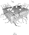
- Fig. 1 discloses a typical prior art automated storage and retrieval system 1 with a framework structure 100 and Fig. 2 and 3 discloses two different prior art container handling vehicles 201,301 suitable for operating on such a system 1.
- the framework structure 100 comprises a number of upright members 102 and a number of horizontal members 103 which are supported by the upright members 102.
- the members 102, 103 may typically be made of metal, e.g. extruded aluminum profiles.
- the framework structure 100 defines a storage grid 104 comprising storage columns 105 arranged in rows, in which storage columns 105 storage containers 106, also known as bins, are stacked one on top of another to form stacks 107.
- the storage grid 104 guards against horizontal movement of the stacks 107 of storage containers 106, and guides vertical movement of the containers 106, but does normally not otherwise support the storage containers 106 when stacked.
- the automated storage and retrieval system 1 comprises a rail system 108 arranged in a grid pattern across the top of the storage 104, on which rail system 108 a plurality of container handling vehicles 201,301 are operated to raise storage containers 106 from, and lower storage containers 106 into, the storage columns 105, and also to transport the storage containers 106 above the storage columns 105.
- the rail system 108 comprises a first set of parallel rails 110 arranged to guide movement of the container handling vehicles 201,301 in a first direction X across the top of the frame structure 100, and a second set of parallel rails 111 arranged perpendicular to the first set of rails 110 to guide movement of the container handling vehicles 201,301 in a second direction Y which is perpendicular to the first direction X.
- the rail system 108 defines grid columns 112 above which the container handling vehicles 201,301 can move laterally above the storage columns 105, i.e. in a plane which is parallel to the horizontal X-Y plane.
- Each prior art container handling vehicle 201,301 comprises a vehicle body 201a,301a, and first and second sets of wheels 201b,301b,201c,301c which enable the lateral movement of the container handling vehicles 201,301 in the X direction and in the Y direction, respectively.
- first and second sets of wheels 201b,301b,201c,301c which enable the lateral movement of the container handling vehicles 201,301 in the X direction and in the Y direction, respectively.
- the first set of wheels 201b,301b is arranged to engage with two adjacent rails of the first set 110 of rails
- the second set of wheels 201c,301c is arranged to engage with two adjacent rails of the second set 111 of rails.
- Each set of wheels 201b,301b 201c,301c can be lifted and lowered, so that the first set of wheels 201b,301b and/or the second set of wheels 201c,301c can be engaged with the respective set of rails 110, 111 at any one time.
- Each prior art container handling vehicle 201,301 also comprises a lifting device (not shown) for vertical transportation of storage containers 106, e.g. raising a storage container 106 from, and lowering a storage container 106 into, a storage column 105.
- the lifting device comprises one or more gripping / engaging devices (not shown) which are adapted to engage a storage container 106, and which gripping / engaging devices can be lowered from the vehicle 201,301 so that the position of the gripping / engaging devices with respect to the vehicle 201,301 can be adjusted in a third direction Z which is orthogonal the first direction X and the second direction Y.
- Each prior art container handling vehicle 201,301 comprises a storage compartment or space for receiving and stowing a storage container 106 when transporting the storage container 106 across the rail system 108.
- the storage space may comprise a cavity arranged centrally within the vehicle body 201a as shown in Fig. 2 and as described in e.g. WO2015/193278A1 .
- Fig. 3 shows an alternative configuration of a container handling vehicles 301 with a cantilever construction. Such a vehicle is described in detail in e.g. NO317366.
- the central cavity container handling vehicles 201 shown in Fig. 2 may have a footprint that covers an area with dimensions in the X and Y directions which is generally equal to the lateral extent of a grid column 112, i.e. the extent of a grid column 112 in the X and Y directions, e.g. as is described in WO2015/193278A1 .
- the term 'lateral' used herein may mean 'horizontal'.
- the central cavity container handling vehicles 101 may have a footprint which is larger than the lateral area defined by a grid column 112, e.g. as is disclosed in WO2014/090684A1 .
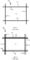
- the rail system 108 may be a single rail system, as is shown in Fig. 4 .
- the rail system 108 may be a double rail system, as is shown in Fig. 5 , thus allowing a container handling vehicle 201 having a footprint generally corresponding to the lateral area defined by a grid column 112 to travel along a row of grid columns even if another container handling vehicle 201 is positioned above a grid column neighboring that row.
- Both the single and double rail system, or a combination comprising a single and double rail arrangement in a single rail system 108 forms a grid pattern in the horizontal plane P comprising a plurality of rectangular and uniform grid locations or grid cells 122, where each grid cell 122 comprises a grid opening 115 being delimited by a pair of tracks 110a,110b of the first tracks 110 and a pair of tracks 111a, 111b of the second set of tracks 111.
- the grid cell 122 is indicated by a dashed box.
- tracks 110a and 110b form pairs of tracks defining parallel rows of grid cells running in the X direction
- tracks 111a and 111b form pairs of tracks defining parallel rows of grid cells running in the Y direction.
- each grid cell 122 has a width W c which is typically within the interval of 30 to 150 cm, and a length L c which is typically within the interval of 50 to 200 cm.
- Each grid opening 115 has a width W o and a length L o which is typically 2 to 10 cm less than the width W c and the length L c of the grid cell 122.
- neighbouring grid cells are arranged in contact with each other such that there is no space there-between.
- a majority of the grid columns 112 are storage columns 105, i.e. grid columns 105 where storage containers 106 are stored in stacks 107.
- a grid 104 normally has at least one grid column 112 which is used not for storing storage containers 106, but which comprises a location where the container handling vehicles 201,301 can drop off and/or pick up storage containers 106 so that they can be transported to an access station (not shown) where the storage containers 106 can be accessed from outside of the grid 104 or transferred out of or into the grid 104.
- such a location is normally referred to as a 'port' and the grid column 112 in which the port is located may be referred to as a 'port column' 119,120.
- the transportation to the access station may be in any direction, that is horizontal, tilted and/or vertical.
- the storage containers 106 may be placed in a random or dedicated grid column 112 within the storage grid 104, then picked up by any container handling vehicle and transported to a port 119,120 for further transportation to an access station.
- the term 'tilted' means transportation of storage containers 106 having a general transportation orientation somewhere between horizontal and vertical.
- the grid 104 in Fig. 1 comprises two port columns 119 and 120.
- the first port column 119 may for example be a dedicated drop-off port column where the container handling vehicles 201,301 can drop off storage containers 106 to be transported to an access or a transfer station
- the second port column 120 may be a dedicated pick-up port column where the container handling vehicles 201,301 can pick up storage containers 106 that have been transported to the grid 104 from an access or a transfer station.
- the access station may typically be a picking or a stocking station where product items are removed from or positioned into the storage containers 106.
- the storage containers 106 are normally never removed from the automated storage and retrieval system 1, but are returned into the grid 104 once accessed.
- a port can also be used for transferring storage containers out of or into the grid 104, e.g. for transferring storage containers 106 to another storage facility (e.g. to another grid or to another automated storage and retrieval system), to a transport vehicle (e.g. a train or a lorry), or to a production facility.
- a conveyor system comprising conveyors is normally employed to transport the storage containers between the ports 119,120 and the access station.
- the conveyor system may comprise a lift device with a vertical component for transporting the storage containers 106 vertically between the port 119,120 and the access station.
- the conveyor system may be arranged to transfer storage containers 106 between different grids, e.g. as is described in WO2014/075937A1 .
- a storage container 106 stored in the grid 104 disclosed in Fig. 1 When a storage container 106 stored in the grid 104 disclosed in Fig. 1 is to be accessed, one of the container handling vehicles 201,301 is instructed to retrieve the target storage container 106 from its position in the grid 104 and transport it to the drop-off port 119.
- This operation involves moving the container handling vehicle 201,301 to a grid location above the storage column 105 in which the target storage container 106 is positioned, retrieving the storage container 106 from the storage column 105 using the container handling vehicle's 201,301 lifting device (not shown), and transporting the storage container 106 to the drop-off port 119. If the target storage container 106 is located deep within a stack 107, i.e.
- the operation also involves temporarily moving the above-positioned storage containers prior to lifting the target storage container 106 from the storage column 105.
- This step which is sometimes referred to as "digging" within the art, may be performed with the same container handling vehicle that is subsequently used for transporting the target storage container to the drop-off port 119, or with one or a plurality of other cooperating container handling vehicles.
- the automated storage and retrieval system 1 may have container handling vehicles specifically dedicated to the task of temporarily removing storage containers from a storage column 105. Once the target storage container 106 has been removed from the storage column 105, the temporarily removed storage containers can be repositioned into the original storage column 105. However, the removed storage containers may alternatively be relocated to other storage columns.
- the container handling vehicles 201,301 When a storage container 106 is to be stored in the grid 104, one of the container handling vehicles 201,301 is instructed to pick up the storage container 106 from the pick-up port 120 and transport it to a grid location above the storage column 105 where it is to be stored. After any storage containers positioned at or above the target position within the storage column stack 107 have been removed, the container handling vehicle 201,301 positions the storage container 106 at the desired position. The removed storage containers may then be lowered back into the storage column 105 or relocated to other storage columns.
- the automated storage and retrieval system 1 For monitoring and controlling the automated storage and retrieval system 1, e.g. monitoring and controlling the location of respective storage containers 106 within the grid 104, the content of each storage container 106; and the movement of the container handling vehicles 201,301 so that a desired storage container 106 can be delivered to the desired location at the desired time without the container handling vehicles 201,301 colliding with each other, the automated storage and retrieval system 1 comprises a control system which typically is computerized and which typically comprises a database for keeping track of the storage containers 106.
- WO2015/104263A2 a storage system is described solving the undesired standstill by arranging a number of charging stations at the perimeter of the storage grid. Each charging station has the capability of charging a power storage source on each vehicle.
- the solution disclosed in WO 2015/104263A2 have disadvantages in that the power supply arrangement reduces both the available space for the storage containers and the overall stability of the vehicles.
- the hook system used to connect the power storage source to the charging station is quite complex and thus more service intensive and prone to failure.
- the prior art hook system limits the potential lateral extent of a connected power storage source due to limited support of the power storage source in the lateral direction.
- WO 2017/220627 A1 discloses a storage system comprising a container handling vehicle having a chargeable power source, and a charging station for charging a plurality of power sources.
- EP 0698530 A1 discloses a plug/socket connection for charging a battery.
- inventive solutions described herein may be considered as representing a further development of the storage system as disclosed in WO2015/104263A2 , where the above-mentioned disadvantages concerning space and stability are mitigated.
- the present invention provides an automated storage and retrieval system comprising:
- the power supply compartment is arranged at a level above the level of the at least one storage compartment.
- the power supply compartment may extend directly above the at least one storage compartment.
- the power supply support is arranged to extend into the power supply compartment to retrieve a discharged power supply or insert a charged power supply.
- the power supply support is arranged such that the supported power supply may only be released in an upwards direction relative the power supply support.
- the power supply support By having the power supply support arranged to extend into the power supply compartment, the power supply may be introduced to a position within the vehicle being laterally separate from a side (or the horizontal circumference) of the container handling vehicle while at the same time being kept sufficiently stable for reliable coupling of the power supply to a connector of the vehicle
- the power supply compartment comprises a power supply locking assembly arranged to hold the power supply in place within the power supply compartment.
- the power supply assembly is arranged to prevent an accommodated power supply from moving relative to the power supply compartment.
- the power supply locking assembly prevents the power supply from moving laterally/horizontally relative the power supply compartment.
- the power supply locking assembly is moveable between a first position, in which the power supply locking assembly may hold the power supply in place, and a second position, wherein the power supply may be moved.
- the power supply locking assembly is locked in the first position by a releasable locking mechanism.
- the power supply support is arranged to interact with the releasable locking mechanism and/or the power supply locking assembly, such that the power supply locking assembly may move into the second position when the power supply support is extended into the power supply compartment to retrieve a discharged power supply or insert a charged power supply.
- the releasable locking mechanism may comprise at least one pivot arm arranged to interact with the power supply support, such that the locking mechanism is released.
- the power supply locking assembly is pivotably connected to the upper part of the container handling vehicle, such that the power supply locking assembly may pivot between the first and second position.
- the power supply support comprises two laterally extending guide arms between which the replaceable power supply may be supported.
- each guide arm may be arranged to extend into the power supply compartment and/or at least an end section of at least one guide arm may be arranged to extend into the power supply compartment and/or at least the section of the guide arms between which the power supply may be supported is arranged to extend into the power supply compartment
- At least one of the guide arms comprises an end for interaction with the releasable locking mechanism and/or the power supply locking assembly.
- At least one of the guide arms may comprise an end for interaction with the releasable locking mechanism and/or the power supply locking assembly, such that the power supply locking assembly may move into the second position.
- the end of at least one of the guide arms may be wedge-shaped.
- the replaceable power supply comprises a support rib arranged on each of two opposite sides of the power supply, each support rib arranged to interact with a corresponding guide arm of the power supply support.
- the support ribs may extend laterally/horizontally at opposite sidewalls of the power supply.
- each support rib comprises a recess or protrusion for interaction with a corresponding protrusion or recess, respectively, arranged on the guide arms.
- the interacting recesses and protrusions are arranged such that the power supply is prevented from lateral movement when supported by the power supply support.
- the power supply locking assembly comprises locking elements, the locking elements arranged to interact with the power supply, optionally via support ribs arranged on each of two opposite sides of the power supply, when the power supply is arranged in the power supply compartment and the power supply locking assembly is in the first position, such that the power supply is prevented from moving in at least a lateral direction.
- the locking elements are arranged on two longitudinal sidewalls interconnected by a structural element, such that the sidewalls are fixed relative to each other.
- the structural element is a power supply cover arranged to at least partly cover the power supply when the power supply is arranged in the power supply compartment and the power supply locking assembly is in the first position.
- the power supply locking assembly is pivotably connected to the upper part of the container handling vehicle via the two longitudinal sidewalls, the structural element or the power supply cover.
- the first set of wheels is moveable between an upper and lower position relative the upper part of the container handling vehicle, such that the level of the power supply compartment relative the first and second set of tracks is moveable between a lower and an upper level, respectively.
- the power supply locking assembly is arranged to be in the first position when the power supply support extends into the power supply compartment and the first set of wheels is in the lower wheel position.
- the power supply locking assembly is arranged to be in the second position when the power supply support extends into the power supply compartment and the first set of wheels is in the upper wheel position.
- the power supply is arranged to be supported by the power supply support, when the power supply support extends into the power supply compartment and the first set of wheels is in the upper wheel position.
- the power supply is arranged to be separate from the power supply support and supported by at least one support surface arranged inside the power supply compartment, when the power supply support extends into the power supply compartment and the first set of wheels is in the lower wheel position.
- the at least one support surface may be an upwards facing surface.
- the charging connection may also be defined as being movable between the lower connection position and the upper connection position relative the power supply support.
- the charging connection may be biased towards the upper connection position by any suitable resilient element, such as a spring.
- the charging connection and the power supply charging connection is a plug/socket connection.
- the charging connection may be a charging socket and the power supply charging connection may be a corresponding power supply charging plug, or vice versa.
- the present invention provides a method of charging a power supply of a container handling vehicle in a storage system according to the first aspect, the method comprises the following steps:
- the power supply compartment is in an upper position relative to the track system during step a).
- the container handling vehicle comprises a lower part displaying at least one storage compartment for storing a storage container and an upper part arranged vertically above the lower part, wherein the power supply compartment is located in the upper part of the container handling vehicle.
- the container handling vehicle and the charging station may comprise any of the features defined in the embodiments of the first aspect.
- the first set of wheels is moved to the upper wheel position in step b), and in the lower wheel position during step a).
- the framework 100 of the automated storage and retrieval system 1 is constructed in accordance with the prior art framework 100 described above in connection with Figs. 1-6 , i.e. a number of upright members 102 and a number of horizontal members 103, which are supported by the upright members 102, and further that the framework 100 comprises a track system 108 of parallel tracks 110,111 in X direction and Y direction arranged across the top of storage columns 105 / grid columns 112.
- the horizontal area of a grid column 112, i.e. the area along the X and Y directions, may be defined by the distance between adjacent rails 110 and 111, respectively (see Figs. 4-6 ).
- the grid 104 is shown with a height of eight cells. It is understood, however, that the grid 104 in principle can be of any size. In particular it is understood that grid 104 can be considerably wider and/or longer and/or deeper than disclosed in Fig. 1 .
- the grid 104 may have a horizontal extent of more than 700x700 grid cells and a depth of more than twelve grid cells.
- all vehicles 3 of of the automated storage and retrieval system 1 comprise a vehicle body 17 and a wheel assembly 18 (or any other rolling means / rolling device) arranged in a lower section or part 17a (see Fig. 12 ) of the vehicle body 17 to enable the lateral movement of the container handling vehicle 3, i.e. the movement of the vehicle 3 in the X and Y directions (see Figs. 7-8 ).
- the wheel assembly / rolling device 18 comprises a first set of wheels 19, which is arranged to engage with a pair of tracks 110a, 110b of the first set of tracks 110, and a second set of wheels 20, which is arranged to engage with a pair of tracks 111a, 111b of the second set of tracks 111 (see Fig. 8 ). At least one of the set of wheels 19, 20 can be lifted and lowered, so that the first set of wheels 19 and/or the second set of wheels 20 can be brought to engage with the respective set of tracks 110, 111 at any one time.
- the lifting / lowering procedure can for example be performed by lifting side plates 25 (see Fig. 12 ) attached to the respective wheels 19,20 by use of a lifting motor arranged in the upper part 17b of the vehicle 3.
- Each set of wheels 19, 20 comprises four wheels 19a, 19b, 19c, 19d; 20a, 20b, 20c, 20d arranged along the sides of the vehicle 3.
- the wheels 19a and 19b are arranged in a first vertical plane, and the wheels 19c and 19d are arranged in a second vertical plane which is parallel to the first vertical plane and arranged at a distance from the first vertical plane which corresponds to the distance between rails 110a and 110b (see e.g. Fig. 8 ).
- the wheels 20a and 20b are arranged in a third vertical plane, which is orthogonal to the vertical planes in which the wheels 19a, 19b, 19c and 19d are arranged, and the wheels 20c and 20d are arranged in a fourth vertical plane which is parallel to the third vertical plane and arranged at a distance from the third vertical plane which corresponds to the distance between the rails 111a and 111b.
- At least one of the wheels in each set 19, 20 is motorized in order to propel the vehicle 3 along the track system 108.
- the at least one motorized wheel in each set 19, 20 comprises a hub motor, i.e. an electric motor that is coupled to, or incorporated into, the hub of a wheel and drives the wheel directly.
- a hub motor i.e. an electric motor that is coupled to, or incorporated into, the hub of a wheel and drives the wheel directly.
- Each container handling vehicle 3 comprises a storage compartment or bin storage space 24 arranged within the lower part 17a of the vehicle body 17 (see Fig. 12 ) for receiving and holding a storage container 106 when transporting the storage container 106 across the track system 108 (see Fig. 8 ).
- the bin storage space 24 can be accessed from below, i.e. from an opening at the bottom of the container handling vehicle 3.
- the bin storage space 24 is arranged centrally or substantially centrally within the vehicle body 17.
- Each container handling vehicle 3 also comprises a lifting device 21 (see Fig. 10 and 12 ) for vertical transportation of a storage container 106, e.g. lifting a storage container 106 from a storage column 105 and bringing it into the bin storage space 24, and also for lowering a storage container 106 from the storage space 24 into a storage column 105.
- the lifting device 21 comprises a gripping device 22 which is arranged to releasably engage with a storage container 106.
- the lifting device 21 also comprises a motorized lifting mechanism 23 for lowering and raising the gripping device 22 so that the position of the gripping device 22 with respect to the vehicle body 17 can be adjusted in a third direction Z, i.e. orthogonal the first direction X and the second direction Y (see also Fig.
- the gripping device 22 comprises remotely operated claws 22a attached underneath a lifting plate 22b.
- the lifting plate 22b may be connected to a plurality belts (not shown) constituting part of the motorized lifting mechanism 23.
- the motorized lifting mechanism 23 is arranged in the upper part 17b of the vehicle body 17 (see Fig. 12 ), below a battery cover or house 27 for mounting of a chargeable battery 28 (see Fig. 10 ) and above the lower part 17a with the bin storage space 24.
- one of the container handling vehicles 3 When a storage container 106 stored in the storage grid 104 is to be accessed, one of the container handling vehicles 3 is instructed to retrieve the target storage container 106 from its position in the storage grid 104 and to transport the target storage container 106 to an access station (not shown) where it can be access from outside of the storage grid 104 or transferred out of the storage grid 104.
- This operation involves moving the container handling vehicle 3 to the grid cell 122 above the storage column 105 in which the target storage container 106 is positioned and retrieving the storage container 106 from the storage column 105 using the container handling vehicle's lifting device 21.
- the lifting device 21 lifts the storage container 106 from the storage column 105 through the grid opening 115 of the grid cell 122 and into the storage space 24 of the vehicle 3.
- the operation also involves temporarily moving the above-positioned storage containers prior to lifting the target storage container 106 from the storage column 105.
- This step which is sometimes referred to as "digging" within the art, may be performed with the same container handling vehicle 3 that is subsequently used for transporting the target storage container 106 to the access station, or with one or a plurality of other cooperating container handling vehicles 3.
- the automated storage and retrieval system 1 may have container handling vehicles specifically dedicated to the task of temporarily removing storage containers from a storage column 105, for example the multi-container handling vehicle 5 shown in Fig. 19 .
- container handling vehicles specifically dedicated to the task of temporarily removing storage containers from a storage column 105, for example the multi-container handling vehicle 5 shown in Fig. 19 .
- the temporarily removed storage containers can be repositioned into the original storage column 105.
- the removed storage containers may alternatively, or in addition, be relocated to other storage columns.
- the access station may typically comprise a grid location at the periphery of the storage grid 104 where the storage container 106 can be accessed manually or transported further using a suitable conveyor system (not shown).
- one of the container handling vehicles 3 When a storage container 106 is to be stored in the storage grid 104, one of the container handling vehicles 3 is instructed to pick up the storage container 106 from a pick-up station (not shown), which may also double as an access station, and transport it to a grid cell 122 above the storage column 105 where it is to be stored. After any storage containers positioned at or above the target position within the storage column stack 107 have been removed, the container handling vehicle 3 positions the storage container 106 at the desired position. The removed storage containers may then be lowered back into the storage column 105 or relocated to other storage columns within the storage grid 104.
- a pick-up station not shown
- the container handling vehicle 3 positions the storage container 106 at the desired position. The removed storage containers may then be lowered back into the storage column 105 or relocated to other storage columns within the storage grid 104.
- the automated storage and retrieval system 1 For monitoring and controlling the automated storage and retrieval system 1 so that a desired storage container 106 can be delivered to the desired location at the desired time without the container handling vehicles 3 colliding with each other, the automated storage and retrieval system 1 comprises a control system, which typically is computerised and comprises a database for monitoring and controlling e.g. the location of the respective storage containers 106 within the storage grid 104, the content of each storage container 106 and the movement of the container handling vehicles 3.
- Each vehicle 3 should thus be equipped with onboard control and communication system 35 comprising suitable transmission and receiving means (i.e. a transmitter - receiver system) to enable transmission and receival of signals from and to the remotely situated control system.
- the container handling vehicles 3 typically communicates with the control system via wireless communication means, e.g. via a WLAN operating under an IEEE 802.11 (WiFi) standard and/or utilising a mobile telecommunication technology such as 4G or higher.
- WiFi IEEE 802.11
- Each container handling vehicle 3 comprises a battery 28 (i.e. a replaceable power supply) which provides power to onboard equipment, including the motorised rolling device 18, the motorised lifting mechanism 23 and the onboard control and communications systems 35.
- a battery 28 i.e. a replaceable power supply
- onboard equipment including the motorised rolling device 18, the motorised lifting mechanism 23 and the onboard control and communications systems 35.
- Each of the container handling vehicles 3 shown in Figs. 7-12 and Figs. 14-16 has a footprint, i.e. a contact area against the track system 108, which has a horizontal extension or area which is equal to or less than the horizontal area of a grid cell 122.
- a footprint i.e. a contact area against the track system 108
- the footprint of the vehicle 3 will not extend beyond the grid cell 122 into a neighbouring grid cell 122.
- the wheels 19a-19d, 20a-20d are arranged around the periphery of the bin storage space 24, and the footprint of the vehicle 3 is larger than the storage space 24 only enough to accommodate the wheels 19a-19d, 20a-20d. In this way, the footprint of the vehicle 3 takes up the minimum possible amount of space in the X-Y plane. Since the bin storage space 24 is positioned between the pair of wheels, i.e. the pairs 19a and 19b, 19c and 19d, 20a and 20b and 20c and20d, the centre of gravity of the vehicle 3 will be located within the footprint 30 also when a storage bin 106 is raised into the storage space 24.
- the vehicle 3 comprises generally vertical side walls 26a-26d (see Figs. 7 , 9-11 and 14-16 ), which are co-planar to the vertical planes in which the wheels 19a-19d; 20a-20d are arranged. Consequently, the lower part of the container handling vehicle 3 has a generally cuboid shape.
- the upper part 17b of the vehicle 3 includes a battery cover 27 which may protrude horizontally in the X direction beyond the otherwise generally vertical side walls 26c and 26d (see e.g. fig. 7 , 9 and 10 ).
- This protruding battery cover 27 is configured to house the battery 28 of the vehicle 3 (see Fig. 10 ).
- any kind of power storage source may be covered by the battery cover 27 or positioned within the battery compartment 27a, such as one or more replaceable batteries, one or more fixed batteries, one or more capacitors, or a combination thereof.
- Positioning the battery 28 (or any other power storage source) in this manner, that is protruding from the vehicles' side walls, may be advantageous since it allows charging and/or battery exchange stations 40 easy access to the battery 28 for charging or battery replacement.
- the protruding battery cover 27 covers a battery compartment or slot 27a (e.g. see Fig. 12 )
- the protruding character of the battery cover 27 may provide advantageous guiding for the battery 28 during battery exchange operation.
- the battery cover 27 is not in any way required to protrude from a side wall of the vehicle to provide a highly advantageous system for charging and replacing batteries.
- the battery cover may also be spaced from a side wall of the vehicle.
- the battery 28 may be placed deeper into the vehicle 3 without causing a significant reduction in the available storage space for the bin 106.
- a deeper arrangement of the batteries compared to the prior art solutions where the batteries are arranged at the vehicles' side walls, increases the overall stability conditions for the vehicle 3.
- the term 'deeper is herein defined relative to the outermost perimeter of the vehicle 3 in the X-Y directions, that is, in a lateral direction towards the vertical axis going through the vehicle's 3 centre of gravity.
- the protruding battery cover 27 may hold downward-looking sensors (not shown), which may be used to establish the position of the vehicle on the track system 108, e.g. the alignment of the vehicle vis-à-vis a grid cell 122, or to establish the position of the vehicle vis-à-vis other vehicles on the track system 108, e.g. when operating the vehicles as a train of vehicles, e.g. as is disclosed in the international patent publication WO 2017/037095 A1 .
- the battery cover 27 When the vehicle 3 is positioned above a grid cell 122, e.g. to access a container 106 in the storage column 105 located vertically below the grid cell 122, the battery cover 27 will in this particular embodiment extend over a neighbouring grid cell 122. In other words, even though the vehicle 3 has a contact area against the rail system 108 which does not extend beyond the horizontal extension of one grid cell 122, it has a vertical projection which occupies more than one grid cell 122.
- Such a configuration would normally prevent a second vehicle 3 from travelling over the neighbouring grid cell 122, i.e. the grid cell into which the protruding battery cover 27 of the first vehicle 3 extends. This could be a problem since it could reduce the overall capacity of the automated storage and retrieval system 1.
- the container handling vehicle 3 comprises a recessed section 29 which is arranged in the upper part 17b opposite to the protruding battery cover 27 (see fig. 12 ).
- the protruding battery cover 27 and the recessed section 29 are arranged at opposite sides of the container handling vehicle 3.
- the recessed section 29 is capable of accommodating the protruding battery cover 27 of other vehicles when they pass over a neighbouring grid cell 122.
- the recessed section 29 has a shape which is complementary to the shape of the protruding battery cover 27 and extends across the whole width of the container handling vehicle 3 in the Y direction, thus allowing vehicles 3 to pass each other over adjacent grid cells 122.
- Figs. 7 - 9 show a first vehicle 3a moving in to operate over a grid cell 122, while a second vehicle 3b is positioned over a neighbouring grid cell 122.
- the protruding battery cover 27a of the first vehicle 3a is accommodated in the recessed section 29 of the second vehicle 3b, thereby allowing the vehicles 3a,3b to pass unhindered.
- the protruding battery cover 27 of each container handling vehicle 3 extends in the X direction and the recessed section 29 extends across the whole width of the vehicle 3 in the Y direction.
- the protruding section may alternatively extend in the Y direction and the recessed section may extend across the whole width of the vehicle 3 in the X direction.
- the vehicle may comprise a protruding battery cover 27 as disclosed above, but where the complementary recessed section 29 is absent.
- each horizontal member making up the track system comprises two tracks. Consequently, each horizontal member is capable of accommodating two or more wheels in parallel.
- the borders between neighbouring grid cells 122 run along the centre-line of the horizontal members, as is indicated in Fig. 5 .
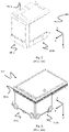
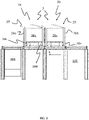
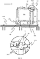
- FIG. 13 An example of a charging and/or battery exchange station 40, hereinafter referred to as a charging station, is shown in Fig. 13 , both in a perspective view ( Fig. 13 A) and in side views along X direction ( Fig. 13 B) and along Y direction ( Fig. 13 C) .
- the charging station 40 is mounted on a charging station base plate 41, which again is fixed (directly or indirectly) to neighbouring rails 110a, 110b, 111a, 111b of the track system 108 above a grid column 112 (see Fig. 8 ) at or near the perimeter of the framework structure 100.
- the particular grid column 112 containing the charging station 40 will hereinafter be referred to as a charging station cell.
- the charging station 40 shown in Fig. 13-16 includes a vertical charging station column 42 fixed at a lower end 42a to the based plate 41.
- a charging socket 45 is arranged at or near an upper end 42b of the column 42, i.e. opposite to the lower end 42a, and electrically connected to a power supply 44, possibly via a power transformer transforming the charging power to the desired power level.
- the charging socket 45 is further configured to receive a charging plug 46 on the battery 28 installed on each vehicle 3 (see. Fig. 17 ), thereby allowing flow of electric power when the charging plug 46 is electrically coupled to the charging socket 45.
- the charging socket 45 is resiliently attached to the charging station 42, such that the position of the charging socket 45 is fixed in an upper (unloaded) position when no external force act on the charging socket 45 and in a lower (loaded) position when the charging socket is exposed to the weight of the electrically connected battery 28.
- This feature ensures that the charging socket 45 and the charging plug 46 is at the same level relative to each other during connection and disconnection. Having the charging socket biased towards the upper position and able to move into a lower position due to the weight of the battery is a highly advantageous feature since it allows for the use of standard plug/socket charging connectors. Without the feature of having a biased charging socket, a plug and socket would have to be able to move vertically relative to each other while being fully connected (i.e. move relative to each other in a direction being perpendicular to the direction in which they move during connection). Although such plug/socket connectors may be envisioned, they would likely be unable to provide a secure connection having a required charging capacity and reliability.
- the charging socket 45 and the charging plug 46 may of course be interchanged.
- any kind of disconnectable electrical connections between the charging station 40 and the battery 28 is possible.
- An automated storage and retrieval system 1 as described herein may comprise a plurality of such charging stations 40, typically arranged along the perimeter of the track system 108. However, one or more charging stations 40 may alternatively or additionally be placed further into the track system 108 and/or fully outside. In the latter configuration, the charging station(s) 40 should be connected to the track system 108 by additional rails in order to allow the vehicles 3 to travel to their respective charging station 40.
- the first set of wheels 19a-d should contact the underlying track system 108 (see Fig. 15 A-D ) and the second set of wheels 20a-d closest to the charging station 30 should be sufficiently high above the track system 108 in order not to interfere with the tracks 111 along the Y direction.
- the vehicle 3 is again lowered towards the track system 108.
- the re-lowering is performed to allow correct alignments with the main battery 28 during the battery exchange process since weight of the battery 28 forces the charging socket 45 down to its lower (loaded) position as explained above.
- a lowering of the vehicle 3 also increases the overall stability of the exchange procedure.
- Typical vertical displacement of the vehicle 3 is 5-15 mm, for example 10 mm.
- the charging station 40 should thus be configured such that the height of the main battery 28 under charge, relative to the track system 108, is approximately equal to the corresponding height of the battery compartment 27a on the vehicle 3 when the vehicle 3 is in a lowered position.
- an auxiliary battery may be installed, for example in the same or similar way as disclosed in the patent publication WO 2015/104263 A1 .
- Other solutions may also be envisaged, for example use of external power sources such as live rails, manual interference, etc.
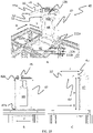
- the available charged battery 28 on the second charging station 40 is mounted onto a battery support 43, which in the example shown in Figs. 13-15 is in form of two guiding pins 43a,43b (i.e. guiding arms) extending laterally into the track system 108 from each side of the charging station column's 42 upper end 42b.
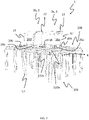
- a release mechanism 50 i.e. a releasable locking mechanism
- a release mechanism 50 is activated, allowing the battery cover 27 to be tilted around a rotational Y axis.
- the release mechanism 50 comprises a pivot arm 51 arranged at each side of the opening of the battery compartment 27a into which the battery 28 should enter.
- each of the protruding ends of the guiding pins 43a,43b displays a tapered section 52 (see Fig. 13 A and C ).
- a pivot arm contact element 51a of each pivot arm 51 is pushed towards the tapered section 52, thereby enforcing an upward directed pivoting movement of the pivot arm 51 (see Fig. 14 A, Fig. 15 D and Fig. 16 ).
- This pivot movements releases a security lock 51b (see Figs. 14 and 18 ) allowing the above-mentioned tilt of the battery cover 27.
- the operation of the release mechanism 50 is illustrated in each of the sequence drawings in Fig. 14 and in Fig. 16 .
- enlarged area drawings of the release mechanism 50 is added in Fig. 14 A-C and Fig. 14 F .
- the enlarged area drawings clearly show the activation of the pivot arm movement upon contact with the tapered section 52 moving the security lock 51b away from the battery cover 27 and the subsequent entry of the battery 28.
- the guiding pins 43 with the attached battery 28 When the guiding pins 43 with the attached battery 28 has entered a certain distance into the battery compartment 27a (see Figs. 14 B and C ), the guiding pins 43 releases a battery lock 27b, 27c that allows further entry until the battery 28 is fully in its end position within the battery compartment 27a.
- the battery lock 27b,c (i.e. a power supply locking assembly) comprises a battery lock activator in the form of a wheel 27b and one or more blocking teeth 27c extending from the inner walls of the battery cover 27 (i.e. from the sidewalls 36 of the power supply locking assembly) and into the battery compartment 27a.
- the battery cover 27 is tilted upwards, thereby displacing the one or more teeth 27c such that the battery 28 and the guiding pins 43a,b may continue the movement deeper into the battery compartment 27a.
- the main function of the battery cover 27 is to act as a constructional element of the battery lock, providing rigidity to the two side walls on which the blocking teeth and the wheel is arranged.
- the battery cover may be any element able to provide adequate support/rigidity to the two side walls (or longitudinal elements) on which the blocking teeth and the wheel is arranged.
- the battery 28 can be electrically connected two both the charging station 40 and i.e. the drive motors for the wheels 19a-d,20a-d.
- the battery cover 27 tilts back to its initial position such that the teeth 27c physically locks or holds the battery 28 within the battery compartment 27a.
- the teeth 27c may enter dedicated recesses 49a within support rails 49 arranged at both sides of the battery 28 (see Fig. 17 ).
- the battery lock 27b,c may be any physical hindrance within the battery compartment 27a.
- the battery lock may comprise one or more protruding wedges that the battery 28 may surpass in one direction, but not in the other. In this configuration, the wedge shape would act as the battery lock activator 27b.
- the second set of wheels 20a-d of the vehicle 3 is lifted from the track system 108 (typically between 5-15 mm), thereby lifting the overall height of the vehicle 3.
- This operation causes the battery 28 to be released from the battery support 43, for example from dedicated pockets or tracks within the first and second guiding pins 43a,b (see Fig. 13A ).
- the blocking of the battery 28 into the battery compartment 27a has the advantage that the battery 28 cannot be unintentionally displaced within the battery cover 27 during operation.
- the steps for transferring the battery 28 from the vehicle 3 to the charging station 40 are essentially equal or similar to the opposite sequence and direction of the above-mentioned steps of transferring the battery 28 from the charging station 40 to the vehicle 3.
- the vehicle 3 is first raised to both allow the vehicle to enter the charging station storage cell without interference of the second set of wheels 20 with the tracks 111 in the second direction (Y) and to align the operative battery 28 with the charging socket 45 of the charging station 40.
- the charging socket 45 is in the exemplary configuration of Figs. 13-16 in an upper, unloaded position.
- the wedged ends 52 of the first and second guiding pins 43a,b first activate the tilt of the battery house 27 via the release mechanism 51, then active the battery lock 27b,c causing the battery cover 27 to tilt upwards, thereby removing the blocking teeth 27c from the corresponding recesses 49a in the support rail 49.
- both the battery cover 27 and the optional release mechanism 50 may be arranged so that they protrude horizontally in the X direction beyond the otherwise generally vertical side walls 26c and 26d. In this way, the overall capacity of each vehicle 3 in the system 1 may be increased significantly without necessitating making the tracks 110,111 wider.
- a configuration with a protruding release mechanism 50 has an additional advantage in that it allows easy manual unlocking of the battery 28. That is, the protruding arrangement allows for exertion of sufficient manual force on the release mechanism 50, an operation that would be difficult if for example the release mechanism 50 was arranged deep within the battery cover 27.
- the protruding configuration described above is also beneficial for ensuring early engagement in the charging station 40.
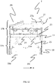
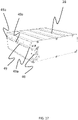
- FIG. 17 An example of a battery 28 is shown in perspective in Fig. 17 .
- One of two support rails 49 is shown protruding from a side wall of the battery 28.
- identical support rail is protruding from the opposite side wall.
- the purpose of the support rails 49 is to both ensure a stable support of the battery 28 on the battery support / guiding pins 43 and to ensure an accurate guiding of the battery 28 into and out of the battery compartment 27a during exchange.
- Fig. 18 shows the battery 28 with support rails 49 being inserted fully within the battery compartment 27a. In the particular configuration shown in Fig. 18 , the battery 28 is approximately half the maximum allowable volume of a battery.
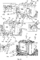
- Figs. 19 and 20 show perspective views of a vehicle 4,5 on a framework structure 100 according a second and third embodiment, respectively.
- the battery supply cover(s) 27 enclosing the battery compartment(s) 27a is for the second and third embodiments arranged above the bin storage space 24.
- Fig. 20 A and B shows an example of a vehicle 5 comprising two battery covers 27 arranged adjacent to another.
- the outer walls and lid of the vehicle 5 have been removed.
- Any exchange of batteries 28 may for this exemplary vehicle 5 use two charging station 40, either one at the time, or simultaneously.
- the vehicle 5 comprises six wheels for each wheel set.
- Figs. 21 and 22 show a second embodiment of a charging station for use with the automated storage and retrieval system.
- the protrusion 32 on the guiding pins 43a,43b are more extended in the lateral direction.
- the charging socket 45 is displaceable in a vertical direction, relative the guiding pins 43a,43b (or alternatively relative the charging station column 42), between an upper position and a lower position.
- the charging socket is shown in the upper position.
- the charging socket 45 is biased towards the upper position by a spring 33.
- the biasing is obtained by having the charging socket 45 slidably connected via a bracket 34a to a column connecting element 34b, and by having the spring arranged between the bracket 34a and the column connecting element 34b, such that the bracket 34a is biased into the upper position.
Landscapes
- Engineering & Computer Science (AREA)
- Mechanical Engineering (AREA)
- Power Engineering (AREA)
- Transportation (AREA)
- Physics & Mathematics (AREA)
- Mathematical Physics (AREA)
- Charge And Discharge Circuits For Batteries Or The Like (AREA)
- Warehouses Or Storage Devices (AREA)
- Electric Propulsion And Braking For Vehicles (AREA)
- Battery Mounting, Suspending (AREA)
Claims (11)
- Automatisiertes Regalbedienungssystem (1), umfassend:ein Schienensystem (108), umfassend einen ersten Satz von parallelen Schienen (110), der auf einer horizontalen Ebene (P) angeordnet ist und sich in einer ersten Richtung (X) erstreckt, und einen zweiten Satz von parallelen Schienen (111), der auf der horizontalen Ebene (P) angeordnet ist und sich in einer zweiten Richtung (Y) erstreckt, die senkrecht zur ersten Richtung (X) ist, wobei der erste und der zweite Satz von Schienen (110, 110) ein Gittermuster auf der horizontalen Ebene (P) bildet, umfassend eine Vielzahl von benachbarten Gitterzellen (122), wobei jede Gitterzelle eine Gitteröffnung (115) umfasst, die durch ein Paar von benachbarten Schienen (110a, 110b) des ersten Satzes von Schienen (110) und ein Paar von benachbarten Schienen (111a, 111b) des zweiten Satzes von Schienen (111) definiert ist;eine Vielzahl von Lagersäulen (105), die sich unter dem Schienensystem (108) befindet, wobei sich jede Lagersäule (105) vertikal unterhalb einer Gitteröffnung (115) befindet und angeordnet ist, um einen Stapel (107) von Lagercontainern (106) zu lagern;ein Containerhandhabungsfahrzeug (3-5) zum Anheben mindestens eines Lagercontainers (106), der in den Stapeln (107) gestapelt ist, wobei das Containerhandhabungsfahrzeug (3-5) dazu konfiguriert ist, sich seitlich auf dem Schienensystem (108) über den Lagersäulen (105) zu bewegen, um durch die Gitteröffnungen (115) auf die Lagercontainer (106) zuzugreifen, wobei das Containerhandhabungsfahrzeug (3-5) einen unteren Teil (17a), der mindestens ein Lagerfach (24) zum Lagern eines Lagercontainers (106), einen oberen Teil (17b), der vertikal über dem unteren Teil (17a) angeordnet ist, eine Radbaugruppe (18) zum Leiten des Containerhandhabungsfahrzeugs (3-5) entlang des Schienensystems (108) und ein Stromversorgungsfach (27a) zum Unterbringen einer austauschbaren Stromversorgung (28) umfasst;eine austauschbare Stromversorgung (28) zur Unterbringung in dem Stromversorgungsfach mit einer Stromversorgungsladeverbindung (46); undeine Ladestation (40) zum Laden der austauschbaren Stromversorgung (28), wobei die Ladestation (40) eine Ladestationsladeverbindung (45), die dazu konfiguriert ist, eine elektrische Verbindung mit der Stromversorgungsladeverbindung (46) herzustellen, wobei die Ladestationsladeverbindung und die Stromversorgungsladeverbindung eine Stecker-Buchse-Verbindung ist, und einen Stromversorgungsträger (43) zum lösbaren Stützen der Stromversorgung (28) während des Ladens umfasst; wobeidas Stromversorgungsfach (27a) in dem oberen Teil (17b) des Containerhandhabungsfahrzeugs (3-5) angeordnet und dazu konfiguriert ist, die austauschbare Stromversorgung (28) über eine Öffnung aufzunehmen, die in die erste Richtung (X) oder die zweite Richtung (Y) gerichtet ist;die Radbaugruppe (18) einen ersten Satz von Rädern (19), der angeordnet ist, um mit dem ersten Satz von Schienen (110) in Eingriff zu treten, und einen zweiten Satz von Rädern (20) umfasst, der angeordnet ist, um mit dem zweiten Satz von Schienen (111) in Eingriff zu treten, wobei der erste Satz von Rädern (19) zwischen einer oberen und einer unteren Radposition bewegbar ist, sodass der erste Satz von Rädern (19) mit dem ersten Satz von Schienen (110) in der unteren Radposition in Eingriff tritt und der zweite Satz von Rädern (20) mit dem zweiten Satz von Schienen (111) in der oberen Radposition in Eingriff tritt;die Stromversorgungsstütze (43) auf einer festen Höhe in Bezug auf das Schienensystem (108) angeordnet ist und die Ladestationsladeverbindung (45) zwischen einer unteren Verbindungsposition und einer oberen Verbindungsposition in Bezug auf das Schienensystem (108) bewegbar ist;- in der unteren Verbindungsposition ist die Ladestationsladeverbindung (45) auf einer Höhe angeordnet, die der Höhe der Stromversorgungsladeverbindung (46) entspricht, wenn die Stromversorgung (28) von der Stromversorgungsstütze (43) gestützt wird; und- in der oberen Verbindungsposition ist die Ladestationsladeverbindung (45) auf einer Höhe angeordnet, die der Höhe der Stromversorgungsladeverbindung (46) entspricht, wenn die Stromversorgung (28) in dem Stromversorgungsfach untergebracht ist und der erste Satz von Rädern (19) in der unteren Radposition ist;wobei die Ladestationsladeverbindung (45) durch ein elastisches Element in Richtung der oberen Verbindungsposition vorgespannt ist.
- System nach Anspruch 1, wobei die Stromversorgungsstütze (43) angeordnet ist, um sich in das Stromversorgungsfach (27a) zu erstrecken, um eine entladene Stromversorgung (28) zu entnehmen oder eine geladene Stromversorgung (28) einzusetzen, und das Stromversorgungsfach (27a) eine Stromversorgungsverriegelungsbaugruppe (27, 27b, 27c) umfasst, die angeordnet ist, um die Stromversorgung (28) an Ort und Stelle innerhalb des Stromversorgungsfachs (27a) zu halten, und die Stromversorgungsverriegelungsbaugruppe (27, 27b, 27c) zwischen einer ersten Position, in der die Stromversorgungsverriegelungsbaugruppe die Stromversorgung an Ort und Stelle halten kann, und einer zweiten Position, in der die Stromversorgung bewegt werden kann, bewegbar ist, und die Stromversorgungsverriegelungsbaugruppe (27, 27b, 27c) durch einen lösbaren Verriegelungsmechanismus (50) in der ersten Position verriegelt ist.
- System nach Anspruch 2, wobei die Stromversorgungsstütze (43) angeordnet ist, um mit dem lösbaren Verriegelungsmechanismus (50) und/oder der Stromversorgungsverriegelungsbaugruppe (27, 27b, 27c) zu interagieren, sodass sich die Stromversorgungsverriegelungsbaugruppe in die zweite Position bewegen kann, wenn sich die Stromversorgungsstütze (43) in das Stromversorgungsfach (27a) erstreckt, um eine entladene Stromversorgung zu entnehmen oder eine geladene Stromversorgung einzusetzen.
- System nach Anspruch 2 oder 3, wobei die Stromversorgungsverriegelungsbaugruppe schwenkbar mit dem oberen Teil (17b) des Containerhandhabungsfahrzeugs (3-5) verbunden ist, sodass die Stromversorgungsverriegelungsbaugruppe zwischen der ersten und der zweiten Position schwenken kann.
- System nach Anspruch 2, wobei die Stromversorgungsstütze (43) zwei sich seitlich erstreckende Führungsarme (43a, 43b) umfasst, zwischen denen die austauschbare Stromversorgung (28) gestützt werden kann, und mindestens einer der Führungsarme (43a, 43b) ein Ende (52) zur Interaktion mit dem lösbaren Verriegelungsmechanismus (50) und/oder der Stromversorgungsverriegelungsbaugruppe umfasst.
- System nach Anspruch 5, wobei die austauschbare Stromversorgung (28) eine Stützrippe (49) umfasst, die auf jeder der zwei gegenüberliegenden Seiten der Stromversorgung angeordnet ist, wobei jede Stützrippe (49) angeordnet ist, um mit einem entsprechenden Führungsarm (43a, 43b) der Stromversorgungsstütze zu interagieren, wobei jede Stützrippe (49) eine Aussparung (49a) oder einen Vorsprung zur Interaktion mit einem entsprechenden Vorsprung (32) bzw. einer entsprechenden Aussparung umfasst, die/der auf den Führungsarmen (43a, 43b) angeordnet ist, und die interagierenden Aussparungen (49a) und Vorsprünge (32) derart angeordnet sind, dass verhindert wird, dass die Stromversorgung (28) sich seitlich bewegt, wenn sie von der Stromversorgungsstütze gestützt wird.
- System nach Anspruch 2, wobei die Stromversorgungsverriegelungsbaugruppe (27, 27a, 27b) Verriegelungselemente (27c) umfasst, wobei die Verriegelungselemente angeordnet sind, um mit der Stromversorgung (28) zu interagieren, optional über Stützrippen (49), die auf jeder der zwei gegenüberliegenden Seiten der Stromversorgung angeordnet sind, wenn die Stromversorgung in dem Stromversorgungsfach angeordnet ist und die Stromversorgungsverriegelungsbaugruppe (27, 27b, 27c) in der ersten Position ist, sodass verhindert wird, dass sich die Stromversorgung in mindestens eine seitliche Richtung bewegt.
- System nach Anspruch 2, wobei die Stromversorgungsverriegelungsbaugruppe (27, 27b, 27c) angeordnet ist, um in der ersten Position zu sein, wenn sich die Stromversorgungsstütze (43) in das Stromversorgungsfach erstreckt und der erste Satz von Rädern (19) in der unteren Radposition ist, und die Stromversorgungsverriegelungsbaugruppe (27, 27b, 27c) angeordnet ist, um in der zweiten Position zu sein, wenn sich die Stromversorgungsstütze (43) in das Stromversorgungsfach erstreckt und der erste Satz von Rädern (19) in der oberen Radposition ist.
- System nach Anspruch 8, wobei die Stromversorgung (28) angeordnet ist, um von der Stromversorgungsstütze (43) gestützt zu werden, wenn sich die Stromversorgungsstütze (43) in das Stromversorgungsfach (27a) erstreckt und der erste Satz von Rädern (19) in der oberen Radposition ist.
- System nach Anspruch 8 oder 9, wobei die Stromversorgung (28) angeordnet ist, um von der Stromversorgungsstütze (43) getrennt zu sein und von mindestens einer Stützfläche (31) gestützt zu werden, die innerhalb des Stromversorgungsfachs angeordnet ist, wenn sich die Stromversorgungsstütze (43) in das Stromversorgungsfach erstreckt und der erste Satz von Rädern (19) in der unteren Radposition ist.
- Verfahren zum Laden einer Stromversorgung (28) eines Containerhandhabungsfahrzeugs (3-5) in einem Lagersystem nach einem der Ansprüche 1-10, wobei das Verfahren die folgenden Schritte umfasst:a) Bewegen des Containerhandhabungsfahrzeugs (3-5) zu einer Position, in der die Stromversorgungsstütze (43) der Ladestation (40) zumindest teilweise in das Stromversorgungsfach (27a) eintritt, das die Stromversorgung (28) enthält, und in der mindestens eine Ladestationsladeverbindung (45) der Ladestation (40) in elektrischen Kontakt mit mindestens einer Stromversorgungsladeverbindung (46) der Stromversorgung (28) gebracht wird, wobei das Stromversorgungsfach (27a) in einer oberen Position in Bezug auf das Schienensystem (108) ist;b) Übertragen der Stromversorgung (28) von dem Stromversorgungsfach (27a) des Containerhandhabungsfahrzeugs (3-5) an die Stromversorgungsstütze (43) durch Einstellen der Höhe des Stromversorgungsfachs (27a) in Bezug auf das zugrundeliegende Schienensystem (108); undc) Umkehren des Containerhandhabungsfahrzeugs (3-5), wobei die Stromversorgung (28) auf der Ladestation (40) geladen werden kann.
Priority Applications (3)
| Application Number | Priority Date | Filing Date | Title |
|---|---|---|---|
| EP24183533.9A EP4410590B1 (de) | 2018-04-25 | 2019-02-15 | Automatisiertes lager- und entnahmesystem |
| EP25201480.8A EP4640591A1 (de) | 2018-04-25 | 2019-02-15 | Automatisiertes lager- und entnahmesystem |
| EP22201412.8A EP4151558B1 (de) | 2018-04-25 | 2019-02-15 | Automatisiertes lager- und entnahmesystem |
Applications Claiming Priority (2)
| Application Number | Priority Date | Filing Date | Title |
|---|---|---|---|
| NO20180586A NO20180586A1 (en) | 2018-04-25 | 2018-04-25 | Charging system for container handling vehicles and method of charging a power supply |
| PCT/EP2019/053875 WO2019206490A1 (en) | 2018-04-25 | 2019-02-15 | An automated storage and retrieval system with a charging station for charging of a replaceable power supply of a container handling vehicle |
Related Child Applications (4)
| Application Number | Title | Priority Date | Filing Date |
|---|---|---|---|
| EP24183533.9A Division EP4410590B1 (de) | 2018-04-25 | 2019-02-15 | Automatisiertes lager- und entnahmesystem |
| EP22201412.8A Division EP4151558B1 (de) | 2018-04-25 | 2019-02-15 | Automatisiertes lager- und entnahmesystem |
| EP22201412.8A Division-Into EP4151558B1 (de) | 2018-04-25 | 2019-02-15 | Automatisiertes lager- und entnahmesystem |
| EP25201480.8A Division EP4640591A1 (de) | 2018-04-25 | 2019-02-15 | Automatisiertes lager- und entnahmesystem |
Publications (2)
| Publication Number | Publication Date |
|---|---|
| EP3784604A1 EP3784604A1 (de) | 2021-03-03 |
| EP3784604B1 true EP3784604B1 (de) | 2022-11-23 |
Family
ID=65494123
Family Applications (4)
| Application Number | Title | Priority Date | Filing Date |
|---|---|---|---|
| EP24183533.9A Active EP4410590B1 (de) | 2018-04-25 | 2019-02-15 | Automatisiertes lager- und entnahmesystem |
| EP19705963.7A Active EP3784604B1 (de) | 2018-04-25 | 2019-02-15 | Automatisiertes regalbedienungssystem mit einer ladestation zum laden einer austauschbaren stromversorgung eines containerhandhabungsfahrzeugs |
| EP25201480.8A Pending EP4640591A1 (de) | 2018-04-25 | 2019-02-15 | Automatisiertes lager- und entnahmesystem |
| EP22201412.8A Active EP4151558B1 (de) | 2018-04-25 | 2019-02-15 | Automatisiertes lager- und entnahmesystem |
Family Applications Before (1)
| Application Number | Title | Priority Date | Filing Date |
|---|---|---|---|
| EP24183533.9A Active EP4410590B1 (de) | 2018-04-25 | 2019-02-15 | Automatisiertes lager- und entnahmesystem |
Family Applications After (2)
| Application Number | Title | Priority Date | Filing Date |
|---|---|---|---|
| EP25201480.8A Pending EP4640591A1 (de) | 2018-04-25 | 2019-02-15 | Automatisiertes lager- und entnahmesystem |
| EP22201412.8A Active EP4151558B1 (de) | 2018-04-25 | 2019-02-15 | Automatisiertes lager- und entnahmesystem |
Country Status (10)
| Country | Link |
|---|---|
| US (3) | US12059966B2 (de) |
| EP (4) | EP4410590B1 (de) |
| JP (3) | JP7339964B2 (de) |
| CN (2) | CN112041246B (de) |
| CA (1) | CA3092272A1 (de) |
| DK (1) | DK3784604T3 (de) |
| ES (2) | ES2938032T3 (de) |
| NO (1) | NO20180586A1 (de) |
| PL (2) | PL4151558T3 (de) |
| WO (1) | WO2019206490A1 (de) |
Families Citing this family (28)
| Publication number | Priority date | Publication date | Assignee | Title |
|---|---|---|---|---|
| NO20180586A1 (en) * | 2018-04-25 | 2019-10-28 | Autostore Tech As | Charging system for container handling vehicles and method of charging a power supply |
| GB201807562D0 (en) | 2018-05-09 | 2018-06-20 | Ocado Innovation Ltd | Apparatus and method for charging a robotic load handling device |
| US11567511B1 (en) * | 2019-06-12 | 2023-01-31 | Amazon Technologies, Inc. | After hours package pick up from a robot |
| NO345918B1 (en) * | 2019-09-16 | 2021-10-18 | Autostore Tech As | Automated storage and retrieval system using an automated loader and methods of replacing power supplies |
| GB202001012D0 (en) * | 2020-01-24 | 2020-03-11 | Ocado Innovation Ltd | Raising and lowering containers |
| CN119348453A (zh) * | 2020-04-03 | 2025-01-24 | 奥动新能源汽车科技有限公司 | 自动对接充电装置、充电总成以及换电站 |
| CN111540260B (zh) * | 2020-04-30 | 2022-05-27 | 东莞市名贝电子科技有限公司 | 一种新能源汽车蓄电池续航能力对比装置 |
| CN111483347B (zh) * | 2020-05-04 | 2021-08-31 | 李龙德 | 带有防坠保护性能的新能源汽车电池更换机器人 |
| CN113650999B (zh) * | 2020-05-12 | 2022-09-27 | 深圳市海柔创新科技有限公司 | 搬运机器人换电方法 |
| NO346054B1 (en) | 2020-06-08 | 2022-01-24 | Autostore Tech As | System and method of determining status of a charging station |
| CN111907351A (zh) * | 2020-08-18 | 2020-11-10 | 幻电科技发展有限公司 | 一种轻小型纯电动汽车快换电基站 |
| NO20201054A1 (en) * | 2020-09-28 | 2022-03-29 | Autostore Tech As | Storage system, container vehicle for a storage system, charging station for a storage system and method of charging a container handling vehicle in a storage system |
| KR102779632B1 (ko) * | 2020-11-13 | 2025-03-12 | 무라다기카이가부시끼가이샤 | 주행차 시스템 |
| EP4251545A1 (de) * | 2020-11-30 | 2023-10-04 | Autostore Technology AS | Ferngesteuertes fahrzeug zur handhabung eines lagerbehälters auf einem schienensystem eines automatisierten regalbedienungssystems |
| NO346543B1 (en) * | 2021-03-09 | 2022-09-26 | Autostore Tech As | A storage system featuring covers arrangeable in storage columns |
| US20230219438A1 (en) * | 2021-05-24 | 2023-07-13 | Mark Ogram | Electric vehicle refueling |
| WO2023041743A1 (en) * | 2021-09-16 | 2023-03-23 | Ocado Innovation Limited | An energy storage system for a load handling device |
| GB2612895B (en) * | 2021-09-16 | 2023-11-29 | Ocado Innovation Ltd | An energy storage system for a load handling device |
| CN113752895B (zh) * | 2021-09-18 | 2023-04-25 | 三一重工股份有限公司 | 换电机器人、换电系统及其工作方法 |
| KR102514054B1 (ko) * | 2022-02-23 | 2023-03-24 | 신함인 | 이동형 전기 자동차용 충전 장치 |
| CN114873236B (zh) * | 2022-03-31 | 2023-12-12 | 苏州博众仪器科技有限公司 | 一种电池入柜系统及电池入柜方法 |
| GB2618072B (en) * | 2022-04-21 | 2024-12-18 | Ocado Innovation Ltd | Load handling device with assigned code |
| US20230398898A1 (en) * | 2022-06-08 | 2023-12-14 | Nimble Robotics, Inc. | Robot Having Interchangeable Batteries |
| KR102790219B1 (ko) * | 2022-07-12 | 2025-04-03 | 신함인 | 이동형 전기 자동차용 충전 장치 |
| NO348519B1 (en) * | 2023-03-27 | 2025-02-24 | Autostore Tech As | Charging station service/inspection tool |
| GB2629584A (en) * | 2023-05-02 | 2024-11-06 | Ocado Innovation Ltd | Load handling device |
| FR3152342A1 (fr) | 2023-08-24 | 2025-02-28 | Exotec | Borne électrique |
| CN118722303B (zh) * | 2024-05-29 | 2024-12-20 | 江阴市富仁高科股份有限公司 | 移动式轨道型充电机器人 |
Family Cites Families (29)
| Publication number | Priority date | Publication date | Assignee | Title |
|---|---|---|---|---|
| US4088232A (en) * | 1974-04-01 | 1978-05-09 | Clark Equipment Co. | Apparatus with storage cells disposed adjacent vertical shafts having covers and a lift means movable thereabove |
| JPH05207611A (ja) | 1992-01-27 | 1993-08-13 | Murata Mach Ltd | 天井走行車のバッテリ自動交換装置 |
| DE9412219U1 (de) * | 1994-07-29 | 1995-11-23 | Varta Batterie Ag, 30419 Hannover | Automatisches Kupplungssystem für Fahrzeugbatterien |
| NO317366B1 (no) | 1999-07-01 | 2004-10-18 | Autostore As | Lagringsanlegg med fjernstyrte vogner med to hjulsett og heisinnretning for drift på skinner anlagt i kryss over kolonner av lagringsenheter som er adskilt med vertikale profilstolper |
| JP3907166B2 (ja) | 2001-08-09 | 2007-04-18 | 本田技研工業株式会社 | 電動小型車両の充電システム |
| US7735996B2 (en) | 2005-05-24 | 2010-06-15 | Varibel B.V. | Connector assembly for connecting an earpiece of a hearing aid to glasses temple |
| AU2008200543B8 (en) * | 2008-02-01 | 2011-01-20 | Smith, Errol John Dr | Light-weight, Mass-producible, Combined Chassis, Battery Housing, Cooling System Structure for Solar Electric Vehicle |
| NL2007566C2 (en) * | 2011-10-11 | 2013-04-15 | Lely Patent Nv | Vehicle system. |
| GB201205807D0 (en) * | 2012-03-30 | 2012-05-16 | Tomtom Int Bv | Mobile device docking station |
| NO334806B1 (no) | 2012-11-13 | 2014-06-02 | Jakob Hatteland Logistics As | Lagringssystem |
| NO335839B1 (no) * | 2012-12-10 | 2015-03-02 | Jakob Hatteland Logistics As | Robot for transport av lagringsbeholdere |
| GB201314313D0 (en) | 2013-08-09 | 2013-09-25 | Ocado Ltd | Apparatus for retrieving units from a storage system |
| GB201404870D0 (en) * | 2014-03-18 | 2014-04-30 | Ocado Ltd | Robotic service device and handling method |
| US9358895B2 (en) * | 2013-10-28 | 2016-06-07 | Meir Avganim | Quick loading and unloading battery system for vehicles |
| NO340313B1 (no) * | 2014-01-08 | 2017-03-27 | Jakob Hatteland Logistics As | Fjernstyrt kjøretøy for å plukke opp lagringsbeholdere fra et lagringssystem, lagringssystem for lagring av beholdere og fremgangsmåte for å bytte en strømkilde |
| NO337544B1 (no) * | 2014-06-19 | 2016-05-02 | Jakob Hatteland Logistics As | Fjernstyrt kjøretøysammenstilling for å plukke opp lagringsbeholdere fra et lagringssystem |
| EP3050824B1 (de) | 2015-01-28 | 2019-10-09 | Autostore Technology AS | Roboter zum Transport von Lagerbehältern |
| NO340577B1 (en) | 2015-09-04 | 2017-05-15 | Jakob Hatteland Logistics As | Method for fetching a target bin stored in a storage system and a storage system which includes a control device operating in accordance with the method |
| PL3374291T3 (pl) * | 2015-11-11 | 2023-07-03 | Ocado Innovation Limited | Systemy i sposoby pobierania |
| GB201521488D0 (en) * | 2015-12-06 | 2016-01-20 | Ocado Innovation Ltd | Sequencing systems and methods |
| NO20160075A1 (en) * | 2016-01-14 | 2017-04-03 | Autostore Tech As | Method for retrieving items from a storage system and storage system for storing and retrieving bins |
| NO20160118A1 (en) * | 2016-01-26 | 2017-07-27 | Autostore Tech As | Remotely operated vehicle |
| GB201603520D0 (en) * | 2016-02-29 | 2016-04-13 | Ocado Innovation Ltd | Robotic service device and handling method |
| CN108698757B (zh) * | 2016-03-03 | 2020-11-24 | 村田机械株式会社 | 输送系统 |
| NO344308B1 (en) | 2016-06-21 | 2019-10-28 | Autostore Tech As | Storage system comprising a charging station assembly and method of replacing the power source of a remotely operated vehicle |
| NO20180586A1 (en) * | 2018-04-25 | 2019-10-28 | Autostore Tech As | Charging system for container handling vehicles and method of charging a power supply |
| US11360465B2 (en) * | 2017-05-16 | 2022-06-14 | Autostore Technology AS | Automated storage and retrieval system |
| NO346327B1 (en) | 2017-05-16 | 2022-06-07 | Autostore Tech As | Automated storage and retrieval system |
| CN107878248A (zh) | 2017-12-01 | 2018-04-06 | 郭春林 | 一种用于为电动汽车提供应急充电的方法及系统 |
-
2018
- 2018-04-25 NO NO20180586A patent/NO20180586A1/en not_active Application Discontinuation
-
2019
- 2019-02-15 CA CA3092272A patent/CA3092272A1/en active Pending
- 2019-02-15 EP EP24183533.9A patent/EP4410590B1/de active Active
- 2019-02-15 ES ES19705963T patent/ES2938032T3/es active Active
- 2019-02-15 JP JP2020558876A patent/JP7339964B2/ja active Active
- 2019-02-15 EP EP19705963.7A patent/EP3784604B1/de active Active
- 2019-02-15 PL PL22201412.8T patent/PL4151558T3/pl unknown
- 2019-02-15 US US16/981,465 patent/US12059966B2/en active Active
- 2019-02-15 ES ES22201412T patent/ES2989213T3/es active Active
- 2019-02-15 EP EP25201480.8A patent/EP4640591A1/de active Pending
- 2019-02-15 CN CN201980028081.7A patent/CN112041246B/zh active Active
- 2019-02-15 PL PL19705963.7T patent/PL3784604T3/pl unknown
- 2019-02-15 CN CN202211233425.8A patent/CN115417052A/zh active Pending
- 2019-02-15 EP EP22201412.8A patent/EP4151558B1/de active Active
- 2019-02-15 WO PCT/EP2019/053875 patent/WO2019206490A1/en not_active Ceased
- 2019-02-15 DK DK19705963.7T patent/DK3784604T3/da active
-
2023
- 2023-08-25 JP JP2023136868A patent/JP7576136B2/ja active Active
-
2024
- 2024-05-16 US US18/666,455 patent/US12319165B2/en active Active
- 2024-10-18 JP JP2024182362A patent/JP2025011283A/ja active Pending
-
2025
- 2025-04-30 US US19/194,056 patent/US20250256601A1/en active Pending
Also Published As
| Publication number | Publication date |
|---|---|
| CN112041246B (zh) | 2022-09-27 |
| ES2989213T3 (es) | 2024-11-25 |
| US20210032036A1 (en) | 2021-02-04 |
| EP4151558A2 (de) | 2023-03-22 |
| CN112041246A (zh) | 2020-12-04 |
| EP4151558B1 (de) | 2024-07-31 |
| JP7339964B2 (ja) | 2023-09-06 |
| EP4151558C0 (de) | 2024-07-31 |
| CN115417052A (zh) | 2022-12-02 |
| US20250256601A1 (en) | 2025-08-14 |
| EP4151558A3 (de) | 2023-05-31 |
| EP4410590A2 (de) | 2024-08-07 |
| PL3784604T3 (pl) | 2023-03-06 |
| DK3784604T3 (da) | 2023-02-13 |
| US20240300356A1 (en) | 2024-09-12 |
| US12059966B2 (en) | 2024-08-13 |
| US12319165B2 (en) | 2025-06-03 |
| JP2021522130A (ja) | 2021-08-30 |
| JP2023159362A (ja) | 2023-10-31 |
| JP2025011283A (ja) | 2025-01-23 |
| JP7576136B2 (ja) | 2024-10-30 |
| PL4151558T3 (pl) | 2024-12-16 |
| EP3784604A1 (de) | 2021-03-03 |
| EP4410590B1 (de) | 2025-10-22 |
| CA3092272A1 (en) | 2019-10-31 |
| EP4410590A3 (de) | 2024-10-09 |
| WO2019206490A1 (en) | 2019-10-31 |
| ES2938032T3 (es) | 2023-04-04 |
| NO20180586A1 (en) | 2019-10-28 |
| EP4640591A1 (de) | 2025-10-29 |
Similar Documents
| Publication | Publication Date | Title |
|---|---|---|
| EP3784604B1 (de) | Automatisiertes regalbedienungssystem mit einer ladestation zum laden einer austauschbaren stromversorgung eines containerhandhabungsfahrzeugs | |
| US12227356B2 (en) | Automated storage and retrieval system | |
| EP4031406B1 (de) | Automatisches lager- und wiederauffindungssystem mit automatischer ladevorrichtung und verfahren zum ersatz von stromversorgungen | |
| EP3634885B1 (de) | Automatisiertes speicherung- und abrufsystem | |
| HK40113321A (en) | Automated storage and retrieval system | |
| HK40077462A (zh) | 自动存储和取回系统、充电站、容器装卸车辆和相关方法 | |
| HK40039597A (en) | An automated storage and retrieval system with a charging station for charging of a replaceable power supply of a container handling vehicle | |
| HK40039597B (en) | An automated storage and retrieval system with a charging station for charging of a replaceable power supply of a container handling vehicle |
Legal Events
| Date | Code | Title | Description |
|---|---|---|---|
| STAA | Information on the status of an ep patent application or granted ep patent |
Free format text: STATUS: UNKNOWN |
|
| STAA | Information on the status of an ep patent application or granted ep patent |
Free format text: STATUS: THE INTERNATIONAL PUBLICATION HAS BEEN MADE |
|
| PUAI | Public reference made under article 153(3) epc to a published international application that has entered the european phase |
Free format text: ORIGINAL CODE: 0009012 |
|
| STAA | Information on the status of an ep patent application or granted ep patent |
Free format text: STATUS: REQUEST FOR EXAMINATION WAS MADE |
|
| 17P | Request for examination filed |
Effective date: 20201026 |
|
| AK | Designated contracting states |
Kind code of ref document: A1 Designated state(s): AL AT BE BG CH CY CZ DE DK EE ES FI FR GB GR HR HU IE IS IT LI LT LU LV MC MK MT NL NO PL PT RO RS SE SI SK SM TR |
|
| AX | Request for extension of the european patent |
Extension state: BA ME |
|
| DAV | Request for validation of the european patent (deleted) | ||
| DAX | Request for extension of the european patent (deleted) | ||
| STAA | Information on the status of an ep patent application or granted ep patent |
Free format text: STATUS: EXAMINATION IS IN PROGRESS |
|
| 17Q | First examination report despatched |
Effective date: 20220223 |
|
| GRAP | Despatch of communication of intention to grant a patent |
Free format text: ORIGINAL CODE: EPIDOSNIGR1 |
|
| STAA | Information on the status of an ep patent application or granted ep patent |
Free format text: STATUS: GRANT OF PATENT IS INTENDED |
|
| INTG | Intention to grant announced |
Effective date: 20220615 |
|
| GRAS | Grant fee paid |
Free format text: ORIGINAL CODE: EPIDOSNIGR3 |
|
| GRAA | (expected) grant |
Free format text: ORIGINAL CODE: 0009210 |
|
| STAA | Information on the status of an ep patent application or granted ep patent |
Free format text: STATUS: THE PATENT HAS BEEN GRANTED |
|
| AK | Designated contracting states |
Kind code of ref document: B1 Designated state(s): AL AT BE BG CH CY CZ DE DK EE ES FI FR GB GR HR HU IE IS IT LI LT LU LV MC MK MT NL NO PL PT RO RS SE SI SK SM TR |
|
| REG | Reference to a national code |
Ref country code: GB Ref legal event code: FG4D |
|
| REG | Reference to a national code |
Ref country code: CH Ref legal event code: EP |
|
| REG | Reference to a national code |
Ref country code: DE Ref legal event code: R096 Ref document number: 602019022199 Country of ref document: DE |
|
| REG | Reference to a national code |
Ref country code: AT Ref legal event code: REF Ref document number: 1533028 Country of ref document: AT Kind code of ref document: T Effective date: 20221215 |
|
| REG | Reference to a national code |
Ref country code: IE Ref legal event code: FG4D |
|
| REG | Reference to a national code |
Ref country code: NL Ref legal event code: FP |
|
| REG | Reference to a national code |
Ref country code: DK Ref legal event code: T3 Effective date: 20230209 |
|
| REG | Reference to a national code |
Ref country code: SE Ref legal event code: TRGR |
|
| REG | Reference to a national code |
Ref country code: LT Ref legal event code: MG9D |
|
| REG | Reference to a national code |
Ref country code: NO Ref legal event code: T2 Effective date: 20221123 |
|
| REG | Reference to a national code |
Ref country code: ES Ref legal event code: FG2A Ref document number: 2938032 Country of ref document: ES Kind code of ref document: T3 Effective date: 20230404 |
|
| REG | Reference to a national code |
Ref country code: AT Ref legal event code: MK05 Ref document number: 1533028 Country of ref document: AT Kind code of ref document: T Effective date: 20221123 |
|
| PG25 | Lapsed in a contracting state [announced via postgrant information from national office to epo] |
Ref country code: PT Free format text: LAPSE BECAUSE OF FAILURE TO SUBMIT A TRANSLATION OF THE DESCRIPTION OR TO PAY THE FEE WITHIN THE PRESCRIBED TIME-LIMIT Effective date: 20230323 Ref country code: LT Free format text: LAPSE BECAUSE OF FAILURE TO SUBMIT A TRANSLATION OF THE DESCRIPTION OR TO PAY THE FEE WITHIN THE PRESCRIBED TIME-LIMIT Effective date: 20221123 Ref country code: FI Free format text: LAPSE BECAUSE OF FAILURE TO SUBMIT A TRANSLATION OF THE DESCRIPTION OR TO PAY THE FEE WITHIN THE PRESCRIBED TIME-LIMIT Effective date: 20221123 Ref country code: AT Free format text: LAPSE BECAUSE OF FAILURE TO SUBMIT A TRANSLATION OF THE DESCRIPTION OR TO PAY THE FEE WITHIN THE PRESCRIBED TIME-LIMIT Effective date: 20221123 |
|
| PG25 | Lapsed in a contracting state [announced via postgrant information from national office to epo] |
Ref country code: RS Free format text: LAPSE BECAUSE OF FAILURE TO SUBMIT A TRANSLATION OF THE DESCRIPTION OR TO PAY THE FEE WITHIN THE PRESCRIBED TIME-LIMIT Effective date: 20221123 Ref country code: LV Free format text: LAPSE BECAUSE OF FAILURE TO SUBMIT A TRANSLATION OF THE DESCRIPTION OR TO PAY THE FEE WITHIN THE PRESCRIBED TIME-LIMIT Effective date: 20221123 Ref country code: IS Free format text: LAPSE BECAUSE OF FAILURE TO SUBMIT A TRANSLATION OF THE DESCRIPTION OR TO PAY THE FEE WITHIN THE PRESCRIBED TIME-LIMIT Effective date: 20230323 Ref country code: HR Free format text: LAPSE BECAUSE OF FAILURE TO SUBMIT A TRANSLATION OF THE DESCRIPTION OR TO PAY THE FEE WITHIN THE PRESCRIBED TIME-LIMIT Effective date: 20221123 Ref country code: GR Free format text: LAPSE BECAUSE OF FAILURE TO SUBMIT A TRANSLATION OF THE DESCRIPTION OR TO PAY THE FEE WITHIN THE PRESCRIBED TIME-LIMIT Effective date: 20230224 |
|
| P01 | Opt-out of the competence of the unified patent court (upc) registered |
Effective date: 20230524 |
|
| PG25 | Lapsed in a contracting state [announced via postgrant information from national office to epo] |
Ref country code: SM Free format text: LAPSE BECAUSE OF FAILURE TO SUBMIT A TRANSLATION OF THE DESCRIPTION OR TO PAY THE FEE WITHIN THE PRESCRIBED TIME-LIMIT Effective date: 20221123 Ref country code: RO Free format text: LAPSE BECAUSE OF FAILURE TO SUBMIT A TRANSLATION OF THE DESCRIPTION OR TO PAY THE FEE WITHIN THE PRESCRIBED TIME-LIMIT Effective date: 20221123 Ref country code: EE Free format text: LAPSE BECAUSE OF FAILURE TO SUBMIT A TRANSLATION OF THE DESCRIPTION OR TO PAY THE FEE WITHIN THE PRESCRIBED TIME-LIMIT Effective date: 20221123 |
|
| REG | Reference to a national code |
Ref country code: DE Ref legal event code: R097 Ref document number: 602019022199 Country of ref document: DE |
|
| PG25 | Lapsed in a contracting state [announced via postgrant information from national office to epo] |
Ref country code: SK Free format text: LAPSE BECAUSE OF FAILURE TO SUBMIT A TRANSLATION OF THE DESCRIPTION OR TO PAY THE FEE WITHIN THE PRESCRIBED TIME-LIMIT Effective date: 20221123 Ref country code: AL Free format text: LAPSE BECAUSE OF FAILURE TO SUBMIT A TRANSLATION OF THE DESCRIPTION OR TO PAY THE FEE WITHIN THE PRESCRIBED TIME-LIMIT Effective date: 20221123 |
|
| PG25 | Lapsed in a contracting state [announced via postgrant information from national office to epo] |
Ref country code: MC Free format text: LAPSE BECAUSE OF FAILURE TO SUBMIT A TRANSLATION OF THE DESCRIPTION OR TO PAY THE FEE WITHIN THE PRESCRIBED TIME-LIMIT Effective date: 20221123 |
|
| PLBE | No opposition filed within time limit |
Free format text: ORIGINAL CODE: 0009261 |
|
| STAA | Information on the status of an ep patent application or granted ep patent |
Free format text: STATUS: NO OPPOSITION FILED WITHIN TIME LIMIT |
|
| PG25 | Lapsed in a contracting state [announced via postgrant information from national office to epo] |
Ref country code: LU Free format text: LAPSE BECAUSE OF NON-PAYMENT OF DUE FEES Effective date: 20230215 |
|
| 26N | No opposition filed |
Effective date: 20230824 |
|
| REG | Reference to a national code |
Ref country code: GB Ref legal event code: 732E Free format text: REGISTERED BETWEEN 20231019 AND 20231025 |
|
| PG25 | Lapsed in a contracting state [announced via postgrant information from national office to epo] |
Ref country code: SI Free format text: LAPSE BECAUSE OF FAILURE TO SUBMIT A TRANSLATION OF THE DESCRIPTION OR TO PAY THE FEE WITHIN THE PRESCRIBED TIME-LIMIT Effective date: 20221123 |
|
| REG | Reference to a national code |
Ref country code: IE Ref legal event code: MM4A |
|
| PG25 | Lapsed in a contracting state [announced via postgrant information from national office to epo] |
Ref country code: IE Free format text: LAPSE BECAUSE OF NON-PAYMENT OF DUE FEES Effective date: 20230215 |
|
| PG25 | Lapsed in a contracting state [announced via postgrant information from national office to epo] |
Ref country code: BG Free format text: LAPSE BECAUSE OF FAILURE TO SUBMIT A TRANSLATION OF THE DESCRIPTION OR TO PAY THE FEE WITHIN THE PRESCRIBED TIME-LIMIT Effective date: 20221123 |
|
| PG25 | Lapsed in a contracting state [announced via postgrant information from national office to epo] |
Ref country code: BG Free format text: LAPSE BECAUSE OF FAILURE TO SUBMIT A TRANSLATION OF THE DESCRIPTION OR TO PAY THE FEE WITHIN THE PRESCRIBED TIME-LIMIT Effective date: 20221123 |
|
| PGFP | Annual fee paid to national office [announced via postgrant information from national office to epo] |
Ref country code: NL Payment date: 20250214 Year of fee payment: 7 |
|
| PGFP | Annual fee paid to national office [announced via postgrant information from national office to epo] |
Ref country code: DE Payment date: 20250219 Year of fee payment: 7 |
|
| PGFP | Annual fee paid to national office [announced via postgrant information from national office to epo] |
Ref country code: DK Payment date: 20250213 Year of fee payment: 7 |
|
| PGFP | Annual fee paid to national office [announced via postgrant information from national office to epo] |
Ref country code: ES Payment date: 20250307 Year of fee payment: 7 |
|
| PGFP | Annual fee paid to national office [announced via postgrant information from national office to epo] |
Ref country code: SE Payment date: 20250214 Year of fee payment: 7 |
|
| PGFP | Annual fee paid to national office [announced via postgrant information from national office to epo] |
Ref country code: NO Payment date: 20250211 Year of fee payment: 7 |
|
| PGFP | Annual fee paid to national office [announced via postgrant information from national office to epo] |
Ref country code: BE Payment date: 20250214 Year of fee payment: 7 Ref country code: CH Payment date: 20250301 Year of fee payment: 7 |
|
| PGFP | Annual fee paid to national office [announced via postgrant information from national office to epo] |
Ref country code: PL Payment date: 20250210 Year of fee payment: 7 Ref country code: FR Payment date: 20250212 Year of fee payment: 7 Ref country code: CZ Payment date: 20250210 Year of fee payment: 7 |
|
| PGFP | Annual fee paid to national office [announced via postgrant information from national office to epo] |
Ref country code: IT Payment date: 20250221 Year of fee payment: 7 Ref country code: GB Payment date: 20250123 Year of fee payment: 7 |
|
| PG25 | Lapsed in a contracting state [announced via postgrant information from national office to epo] |
Ref country code: CY Free format text: LAPSE BECAUSE OF FAILURE TO SUBMIT A TRANSLATION OF THE DESCRIPTION OR TO PAY THE FEE WITHIN THE PRESCRIBED TIME-LIMIT; INVALID AB INITIO Effective date: 20190215 |
|
| PG25 | Lapsed in a contracting state [announced via postgrant information from national office to epo] |
Ref country code: HU Free format text: LAPSE BECAUSE OF FAILURE TO SUBMIT A TRANSLATION OF THE DESCRIPTION OR TO PAY THE FEE WITHIN THE PRESCRIBED TIME-LIMIT; INVALID AB INITIO Effective date: 20190215 |