EP3784592B1 - System und schutzvorrichtung zum schützen eines rohrendes - Google Patents
System und schutzvorrichtung zum schützen eines rohrendes Download PDFInfo
- Publication number
- EP3784592B1 EP3784592B1 EP19708235.7A EP19708235A EP3784592B1 EP 3784592 B1 EP3784592 B1 EP 3784592B1 EP 19708235 A EP19708235 A EP 19708235A EP 3784592 B1 EP3784592 B1 EP 3784592B1
- Authority
- EP
- European Patent Office
- Prior art keywords
- protector
- engaging portion
- pipe
- bumper
- engaging
- Prior art date
- Legal status (The legal status is an assumption and is not a legal conclusion. Google has not performed a legal analysis and makes no representation as to the accuracy of the status listed.)
- Active
Links
Images


Classifications
-
- B—PERFORMING OPERATIONS; TRANSPORTING
- B65—CONVEYING; PACKING; STORING; HANDLING THIN OR FILAMENTARY MATERIAL
- B65D—CONTAINERS FOR STORAGE OR TRANSPORT OF ARTICLES OR MATERIALS, e.g. BAGS, BARRELS, BOTTLES, BOXES, CANS, CARTONS, CRATES, DRUMS, JARS, TANKS, HOPPERS, FORWARDING CONTAINERS; ACCESSORIES, CLOSURES, OR FITTINGS THEREFOR; PACKAGING ELEMENTS; PACKAGES
- B65D59/00—Plugs, sleeves, caps, or like rigid or semi-rigid elements for protecting parts of articles or for bundling articles, e.g. protectors for screw-threads, end caps for tubes or for bundling rod-shaped articles
-
- E—FIXED CONSTRUCTIONS
- E21—EARTH OR ROCK DRILLING; MINING
- E21B—EARTH OR ROCK DRILLING; OBTAINING OIL, GAS, WATER, SOLUBLE OR MELTABLE MATERIALS OR A SLURRY OF MINERALS FROM WELLS
- E21B17/00—Drilling rods or pipes; Flexible drill strings; Kellies; Drill collars; Sucker rods; Cables; Casings; Tubings
- E21B17/006—Accessories for drilling pipes, e.g. cleaners
-
- F—MECHANICAL ENGINEERING; LIGHTING; HEATING; WEAPONS; BLASTING
- F16—ENGINEERING ELEMENTS AND UNITS; GENERAL MEASURES FOR PRODUCING AND MAINTAINING EFFECTIVE FUNCTIONING OF MACHINES OR INSTALLATIONS; THERMAL INSULATION IN GENERAL
- F16L—PIPES; JOINTS OR FITTINGS FOR PIPES; SUPPORTS FOR PIPES, CABLES OR PROTECTIVE TUBING; MEANS FOR THERMAL INSULATION IN GENERAL
- F16L57/00—Protection of pipes or objects of similar shape against external or internal damage or wear
- F16L57/005—Protection of pipes or objects of similar shape against external or internal damage or wear specially adapted for the ends of pipes
-
- B—PERFORMING OPERATIONS; TRANSPORTING
- B65—CONVEYING; PACKING; STORING; HANDLING THIN OR FILAMENTARY MATERIAL
- B65D—CONTAINERS FOR STORAGE OR TRANSPORT OF ARTICLES OR MATERIALS, e.g. BAGS, BARRELS, BOTTLES, BOXES, CANS, CARTONS, CRATES, DRUMS, JARS, TANKS, HOPPERS, FORWARDING CONTAINERS; ACCESSORIES, CLOSURES, OR FITTINGS THEREFOR; PACKAGING ELEMENTS; PACKAGES
- B65D59/00—Plugs, sleeves, caps, or like rigid or semi-rigid elements for protecting parts of articles or for bundling articles, e.g. protectors for screw-threads, end caps for tubes or for bundling rod-shaped articles
- B65D59/06—Caps
Definitions
- the present invention relates to a protector for protecting an end of a pipe (pipe end protector) and a system comprising a pipe and a protector.
- the present invention in particular relates to thread protectors and/or thread protector assemblies and, more particularly, thread protectors and/or assemblies for oilfield tubulars such as surface casing, casing, tubing, and other threaded connections.
- Pipe end protectors for industrial pipes are preferably used during handling, transport and storage of pipes.
- pipe end protectors are adapted to protect pipes, in particular the pipe ends, from damages which might occur during handling, transport and/or storage of the pipes.
- pipe or “pipes” shall be construed broadly to encompass any in particular metallic tubular members including, but not limited to, oilfield tubulars, pipes, tubes, connectors, conduits, fittings, and the like.
- pipe preferably refers to a preferably elongated device for the transportation of an in particular liquid and/or gaseous medium, such as oil or gas, and/or for the fluidic connection between two sites.
- a pipe is a hollow cylinder and/or comprises a circular cross-section.
- Industrial pipes preferably for the use in oilfield applications, are typically produced in sections, each having a length of more than one meter, e.g. 1.8 to 12.2 m.
- the pipes are connectable to one another and/or to other devices using various designs and methods at the (finished) ends of the sections.
- pipes in particular oilfield tubulars having a length of pipe, comprise a box end (box), also referred to as the female portion/end, having internal threads and/or a pin end (pin), also referred to as the male portion/end, having external threads.
- box also referred to as the female portion/end
- pin also referred to as the male portion/end
- non-threaded or "plain" pipes might be used and/or connected to one another, e.g. by means of a slip-joint connection and/or welding.
- each of these preferably threaded ends requires a different (thread) protector.
- (thread) protectors for the box of a pipe hereinafter also referred to as box protectors, preferably comprise a tubular (body) portion which can have a frustoconical outer surface which is externally threaded to form a tapered threaded portion, in case the box threads are tapered, or a cylindrical outer surface with straight threads in the event the box threads are straight.
- Box (thread) protectors also might have a radially outwardly extending annular flange attached to one end of the body portion and which preferably has an outside diameter which is equal to or greater than the outside diameter of the pipe such that when the (thread) protector is inserted or screwed into the box of the pipe, the flange engages the end of the pipe on which the box is formed, and can also extend radially outwardly beyond the outside diameter of the pipe.
- tubular (body) portion which is optionally internally threaded with threads to match the threads on the pin, e.g. they can be straight or tapered, depending upon the threads of the pin.
- Pin end (thread) protectors also preferably include an annular flange connected to the body which overlies the end of the pipe wherein the outside diameter of the flange is larger than the outside diameter of the pipe.
- the surface casing In the drilling of an oil/gas well, initially large diameter pipe known as surface casing is preferably placed in the borehole.
- the surface casing can range in diameter from 0.47 to 1.22 m outside diameter.
- this large diameter surface casing preferably lies horizontally on a barge or the like adjacent the platform.
- the surface casing is preferably either grasped in the middle or on opposing ends, depending on the type of pipe handling equipment on the rig, and then preferably raised by the pipe handling apparatus to the floor of the platform.
- the surface casing While it is being raised from the barge to the platform, the surface casing is preferably horizontally oriented. Accordingly, it can rotate to some extent about an axis transverse to the pipe meaning that the ends of the pipe can strike structural portions of the platform, which can damage the ends/threads, or in more severe cases, bend the end(s) of the pipe out of its generally circular cross-sectional form.
- Conventional protectors are made out of plastic or metal.
- US 3,485,271 A discloses a protector comprising an outer portion and an inner portion wherein the outer portion is fabricated from a relatively harder resilient or elastomeric material and the inner portion is fabricated from a relatively softer resilient material.
- the inner portion permits the threads of a pipe to dig into the softer resilient material when loads are applied to the thread protector.
- the known plastic protectors are very expensive and have an insufficient resistance to impacts due to the high pipe body weight.
- the known metal protectors are subjected to electrolytic corrosion due to dissimilarities between the metal of the protector and the pipe body.
- the task of the present invention is to avoid or at least to reduce the aforementioned disadvantages and/or to provide an improved protector for an end of a pipe, preferably wherein a simple, cost-effective, light, robust and/or shock resistant construction is possible or facilitated.
- the protector comprises an engaging portion and a bumper portion, preferably wherein the engaging portion and the bumper portion are in particular directly and/or radially connected to one another, preferably by glueing, welding and/or screwing.
- the engaging portion is preferably at least partially, mostly preferred completely, made out of a polymeric material, preferably plastic material, in particular (pure) polypropylene and/or (pure) polyethylene.
- the bumper portion is preferably softer, i.e. less hard, than the engaging portion or vice versa and/or has a shore D hardness that is lower than the shore D hardness of the engaging portion or vice versa.
- hardness is a material property and preferably refers to the resistance of a material, in particular the engaging portion and/or the bumper portion, to (localized) plastic deformation used by either mechanical indentation or abrasion.
- the hardness may depend on ductility, elastic stiffness, plasticity, strain, strength, toughness, viscoelasticity and viscosity.
- the hardness of a material is preferably be measured by three main types of hardness measurements: scratch hardness, indentation hardness and rebound hardness. Common indentation hardness scales are Rockwell, Vickers, Shore and Brinell, among others.
- the hardness is preferably determined by means of an indentation hardness test and/or a durometer and/or according to DIN EN ISO 868:2003-10 and/or DIN ISO 7619-1:2012-02.
- the depth of an indentation in the material created by a predefined force is preferably measured.
- the shore scale is used, in particular the shore D scale.
- the protector is designed to protect the pipe end in particular during storage, transportation or handling.
- the engaging portion is adapted to - directly and/or radially - interact with the pipe and/or connect the protector to the pipe.
- the protector is attached to the pipe by means of the engaging portion.
- the engaging portion preferably has a sufficient hardness to engage the pipe and/or to connect/disconnect the protector to/from the pipe, in particular by means of screwing/unscrewing. Further, due to the hardness of the engaging portion, the protector resists axial pull-off or stripping during handling practices.
- the bumper portion is preferably adapted to protect the pipe, in particular its end, and/or the engaging portion, mostly preferred against mechanical impacts.
- the bumper portion serves as a damper and/or shock absorber.
- the bumper portion at least partially absorbs vibrations and/or (mechanical) impacts on the protector, in particular its engaging portion, and the pipe.
- the bumper portion might be equipped with air pockets and/or is spongelike, in particular in order to provide the sufficient softness.
- the protector due to the combination of the engaging portion and the bumber portion and/or the different hardness of the protector, it is possible to rigidly and/or detachably connect the protector to the pipe and, further, to effectively protect the pipe against impacts.
- the bumper portion and/or the engaging portion is at least partially, mostly preferred completely, made out of an elastomer, in particular a thermoplastic elastomer (TPE).
- TPE thermoplastic elastomer
- the material of the bumper portion differs from the material of the engaging portion.
- the engaging portion is at least partially, preferably completely, made out of thermoplastic, e.g. (pure) polypropylene and/or (pure) polyethylene
- the bumber portion is at least partially, preferably completely, made out of an in particular thermoplastic elastomer.
- the bumper portion is at least partially, preferably completely, made out of thermoplastic, e.g. (pure) polypropylene and/or (pure) polyethylene
- the engaging portion is at least partially, preferably completely, made out of an in particular thermoplastic elastomer.
- Thermoplastics in particular polypropylene as well as polyethylene, are plastics which can provide the needed hardness and/or strength of the engaging portion, whereas elastomers are plastics which can provide the needed softness, elasticity and/or ductility of the bumper portion.
- the engaging portion and the bumper portion comprise and/or are at least partially made out of an elastomer, in particular a thermoplastic elastomer, or a thermoplastic, preferably wherein the bumper portion is softer than the engaging portion and/or has a shore D hardness that is lower than the shore D hardness of the engaging portion.
- its material might include additives and/or fillers, wherein the additives and/or fillers may be any material suitable for absorbing the impact force transmitted to the engaging portion and/or the pipe ends and/or for decreasing the hardness of the bumper portion.
- its material may include additives and/or fillers, wherein the additives and/or fillers may be any material suitable for increasing the hardness and/or strength of the engaging portion.
- the engaging portion in particular its material, is - in particular not only harder but also - more brittle and/or stiffer than the bumper portion, in particular its material.
- the bumper portion is - in particular not only softer but also - tougher and/or more ductile and/or more elastic than the engaging portion.
- brittleness is a material property and preferably refers to the tendency of a material to fracture with very little or no detectable plastic deformation beforehand. The opposite of brittleness is ductility.
- stiffness preferably defines the extent to which an object - or here the engaging portion - resists deformation in response to an applied force.
- toughness is a material property and/or preferably the ability of a material to absorb energy and/or plastically deform without fracturing.
- toughness is defined as the material's resistance to fracture when stressed.
- elasticity is a material property and/or preferably the ability of a material to elastically deform in response to an applied force and/or to return to its original size/shape/form when the applied force is removed.
- the material is preferably both, strong and ductile.
- the toughness can be determined by integrating the stress-strain curve and is the energy of mechanical deformation per unit volume prior to fracture.
- the toughness of a material is preferably determined by performing an impact test, e.g. Charpy impact test or Izod impact test, mostly preferred according to DIN EN ISO 179-1:2010-11.
- an impact test e.g. Charpy impact test or Izod impact test, mostly preferred according to DIN EN ISO 179-1:2010-11.
- brittle materials that are strong but have a limited ductility are mostly not tough.
- the toughness and/or the brittleness of a material preferably varies with a temperature variation.
- the toughness decreases and/or the brittleness of a material increases with a decreasing temperature.
- the toughness and/or ductility of the bumper portion is higher than the toughness and/or ductility of the engaging portion even at low temperatures, preferably below 273.15 K, in particular below 253.15 K or 223.15 K.
- the protector Due to the bumper portion, in particular its toughness and/or ductility, it is possible to use the protector in extreme weather conditions, in particular in very cold regions, and/or at a temperature below 273.15 K, preferably below 253.15 K or 223.15 K.
- the bumper portion preferably serves as a splinter/burst protection or a splinter/burst guard and/or ensures or increases the operational capability and/or the usability of the protector, in particular of the engaging portion, mostly preferred at the aforementioned temperature.
- the bumper portion preferably provides the dimensional/structural/form stability of the protector.
- the engaging portion is held together by the bumper portion, even in case the engaging portion comprises one or several ruptures.
- the protector can be embodied as a pin protector or a box protector.
- a protector that is embodied as a pin protector might be at least partially attached/plugged on the pipe, in particular its end that is embodied as a pin end.
- a protector that is embodied as a box protector might be at least partially inserted/plugged in the pipe, in particular its end that is embodied as a box end.
- the bumper portion preferably covers the engaging portion and/or an axial end thereof on a side facing away from the pipe, to the outside and/or radially.
- the bumper portion preferably surrounds the engaging portion radially and/or covers the engaging portion to the outside.
- the engaging portion is preferably - at least partially - arranged within the bumper portion and/or the inner diameter of bumper portion is preferably larger than the outer diameter of the engaging portion.
- the engaging portion preferably surrounds the bumper portion radially and/or the bumper portion covers the engaging portion to the inside.
- bumper portion is preferably - at least partially - arranged within the engaging portion and/or the outer diameter of bumper portion is preferably smaller than the inner diameter of the engaging portion.
- the protector is embodied as a thread protector and/or adapted to protect a threaded end of a pipe. Therefore, the engaging portion may comprise a thread for the threaded pipe.
- the thread of the protector can be an external thread or an internal thread depending on the thread of the pipe.
- the proposed system comprises at least one pipe and at least one protector, wherein the protector is (directly) attached to the pipe, in particular its axial end.
- the protector is (directly) attached to the pipe, in particular its axial end.
- the coefficient of thermal expansion of the engaging portion corresponds to and/or matches the coefficient of thermal expansion of the pipe, in particular such that the protector does not disengage from the threads due to temperature variations and/or such that thermal stresses are reduced.
- the coefficient of thermal expansion is a material property and/or a value of a material indicating its tendency to change in shape, area and/or volume in response to a temperature change, preferably wherein the coefficient of thermal expansion is a substance-specific value in the unit K -1 .
- a high coefficient of thermal expansion indicates a high change in shape, area and/or volume in response to a change in temperature and a low coefficient of thermal expansion indicates a low change in shape, area and/or volume in response to a change in temperature.
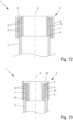
- the system comprises a plurality of pipes and at least one support in order to space the pipes apart from one another and/or to hold the pipe spaced apart from one another. In this way, a collision of pipes, e.g. during transportation, can be avoided.
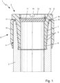
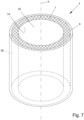
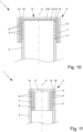
- Fig. 1 is a schematic section of a proposed system 1 comprising a pipe 2 and a proposed protector 3 for protecting the pipe 2, in particular an axial end 4 thereof.
- the protector 3 is preferably adapted to protect the pipe 2, in particular its end 4, against damages, e.g. that might occur during transportation, as already mentioned.
- the protector 3 is preferably embodied as a cover, cap and/or insert, in particular depending on the pipe 2 to be protected, as will be explained in the following.
- the protector 3 is embodied as an insert and/or adapted to be at least partially inserted/placed into the pipe 2, in particular its end 4.
- the protector 3 is adapted to protect the interior and/or the inner side of the pipe 2, in particular its end 4.
- Fig. 1 shows a box protector 3.
- the protector 3 is at least partially plugged/pushed/placed on the pipe 2, in particular its end 4.
- the protector 3 can also be adapted to protect the exterior and/or the outer side of the pipe 2, in particular its end 4.
- the protector 3 is preferably adapted to cover the pipe 2, in particular its end 4, to the outside and to the inside and/or to protect the interior and the exterior of the pipe 2, in particular its end 4, as will be explained in the following in detail.
- the pipe 2 in particular its end 4, might be equipped with a thread 5.
- the protector 3 is embodied as a thread protector and/or comprises a thread 6, preferably wherein the thread 6 of the protector 3 corresponds to and/or matches the thread 5 of the pipe 2.
- the protector 3 is embodied to protect the pipe thread 5 against damages, in particular during transportation, as already mentioned.
- the pipe 2 comprises an internal thread 5 and the protector 3 comprises an external thread 6.
- the pipe 2, in particular its end 4, is embodied as a box and/or adapted to receive another pipe (not shown).
- the protector 3 is embodied as a box protector and/or adapted to protect the internal thread 5 of the pipe 2.
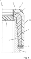
- the (thread) protectors 3 of the present invention be they for pin connections or box connections, preferably have a (first) portion 7 which is preferably threaded to correspond to the threads 5 of the pin or box, respectively (thread engaging portion).
- the (thread) protectors 3 have a shore D hardness of from about 60 - 70.
- the (thread) protector 3 comprises a bumper portion 8, in particular at the axial end of the protector 3.
- the bumper portion 8 (bumper) preferably does not engage the threads 5 of the pin or box, respectively, and/or is softer (than the thread engaging portion 7), preferably having a shore D hardness of less than about 50, preferably about 40 - 50.
- the (thread) engaging portion 7 is in particular characterized by having a coefficient of thermal expansion (COE) which is sufficiently similar to the COE of the metal forming the threads 5, in particular such that the (thread) protectors 3 do not become disengaged from the threads 5 when the threaded connections are subjected to wide temperature swings.
- COE coefficient of thermal expansion
- the (thread) protectors 3 can include additives and fillers to tailor their properties, as already mentioned.
- the fillers used, particularly in the (thread) engaging portion 7, can include a wide variety of materials, such as calcium carbonate, talc, silica, wollastonite, clay, calcium sulfate fibers, mics, glass beads, alumina trihydrate, carbon fiber, fibers of thermosetting resins, etc.
- the tubular members/pipe 2 to which the (thread) protectors 3 are attached can readily formulate the (thread) engaging portion 7 from a composition comprised for example of polypropylene and suitable fillers to accommodate the expected expansion / contraction of the metal forming the threads 5 of the tubular member/pipe 2.
- the bumper portion 8 can preferably be made of and/or comprise a polymeric material.
- the flange 9 is covered/protected by means of the bumper portion 8, preferably radially and/or axially.
Landscapes
- Engineering & Computer Science (AREA)
- Mechanical Engineering (AREA)
- Life Sciences & Earth Sciences (AREA)
- Geology (AREA)
- Mining & Mineral Resources (AREA)
- General Engineering & Computer Science (AREA)
- Physics & Mathematics (AREA)
- Environmental & Geological Engineering (AREA)
- Fluid Mechanics (AREA)
- General Life Sciences & Earth Sciences (AREA)
- Geochemistry & Mineralogy (AREA)
- Protection Of Pipes Against Damage, Friction, And Corrosion (AREA)
Claims (15)
- Protektor (3) zum Schutz von Gewinden (5) an Rohren (2), wobei der Protektor (3) einen Eingriffsabschnitt (7) und einen Stoßdämpferabschnitt (8) aufweist, der den Eingriffsabschnitt (7) radial abdeckt, wobei der Eingriffsabschnitt (7) aus einem Polymermaterial besteht undwobei der Eingriffsabschnitt (7) ein Innengewinde aufweist,dadurch gekennzeichnetdass der Protektor (3) einen Boden (11) aufweist, der den Protektor (3) axial verschließt, wobei der Boden (11) und der Eingriffsabschnitt (7) einstückig ausgebildet sind,wobei der Stoßdämpferabschnitt (8) weicher ist als der Eingriffsabschnitt (7) und eine Shore-D-Härte aufweist, die niedriger ist als die Shore-D-Härte des Eingriffsabschnitts (7).
- Protektor nach Anspruch 1, wobei der Eingriffsabschnitt (7) eine Shore-D-Härte von etwa 60 bis 70 aufweist und/oder wobei der Stoßdämpferabschnitt (8) eine Shore-D-Härte von weniger als 50, vorzugsweise etwa 40 bis 50, aufweist.
- Protektor nach Anspruch 1 oder 2, wobei der Eingriffsabschnitt (7) aus Polypropylen und/oder Polyethylen besteht.
- Protektor nach einem der voranstehenden Ansprüche, wobei der Stoßdämpferabschnitt (8) zumindest teilweise aus einem Elastomer, insbesondere einem thermoplastischen Elastomer, besteht.
- Protektor nach einem der voranstehenden Ansprüche, wobei der Eingriffsabschnitt (7) härter und/oder spröder ist als der Stoßdämpferabschnitt (8) und/oder wobei der Stoßdämpferabschnitt (8) duktiler, elastischer und/oder zäher ist als der Eingriffsabschnitt (7).
- Protektor nach einem der voranstehenden Ansprüche, wobei der Protektor (3), insbesondere der Eingriffsabschnitt (7) und/oder der Stoßdämpferabschnitt (8), als Hohlzylinder, Kappe und/oder Ring ausgebildet ist/sind.
- Protektor nach einem der voranstehenden Ansprüche, wobei der Eingriffsabschnitt (7) dicker ist als der Stoßdämpferabschnitt (8), vorzugsweise um einen Faktor von mindestens 1,2 oder 2 und/oder höchstens 10 oder 8.
- Protektor nach einem der voranstehenden Ansprüche, wobei der Protektor (3) einen Flanschabschnitt (9, 16, 18) aufweist, vorzugsweise wobei der Flanschabschnitt (9, 16, 18) und/oder der Boden (11) ein axiales Ende und/oder einen radialen Vorsprung und/oder eine Ausbuchtung des Protektors (3) umfasst oder bildet und/oder wobei der Flanschabschnitt (9, 16, 18) den Boden (11) des Protektors (3) bildet und/oder den Protektor (3) axial verschließt und/oder den Protektor (3) radial vergrößert.
- Protektor nach Anspruch 8, wobei der Flanschabschnitt (9, 16, 18) durch den Stoßdämpferabschnitt (8) gebildet wird.
- Protektor nach Anspruch 8 oder 9, wobei der Stoßdämpferabschnitt (8) und der Flanschabschnitt (9, 16, 18) einstückig ausgebildet sind.
- Protektor nach einem der voranstehenden Ansprüche, wobei der Protektor (3) eine vorzugsweise zylindrische und/oder ringartige Aufnahme (20) zur Aufnahme eines Rohrs (2) aufweist, vorzugsweise wobei die Aufnahme (20) durch den Eingriffsabschnitt (7) radial und/oder durch den Flanschabschnitt (9, 16, 18) axial begrenzt ist.
- Protektor nach einem der voranstehenden Ansprüche, wobei der Protektor (3) einen rohrförmigen Abschnitt (15) aufweist, wobei der rohrförmige Abschnitt (15) radial von dem Eingriffsabschnitt (7) beabstandet ist und/oder wobei die Aufnahme (20) durch den rohrförmigen Abschnitt (15) und durch den Eingriffsabschnitt (7) radial begrenzt ist.
- Protektor nach einem der voranstehenden Ansprüche, wobei der Außendurchmesser des Eingriffsabschnitts (7) kleiner ist als der Innendurchmesser des Stoßdämpferabschnitts (8).
- System (1), das ein Rohr (2) und mindestens einen Protektor (3) zum Schutz eines axialen Endes (4) des Rohrs (2) aufweist,
wobei der Protektor (3) nach einem der voranstehenden Ansprüche ausgebildet ist. - System nach Anspruch 14, wobei das System (1) mehrere Rohre (2) und mindestens eine Halterung (21) aufweist, um die Rohre (2) voneinander zu beabstanden und/oder die Rohre (2) voneinander beabstandet zu halten, vorzugsweise wobei die Halterung (21) als Rahmen (22) oder als insbesondere spiralförmiger Ring (23) ausgebildet ist.
Applications Claiming Priority (2)
| Application Number | Priority Date | Filing Date | Title |
|---|---|---|---|
| US201862662525P | 2018-04-25 | 2018-04-25 | |
| PCT/EP2019/053296 WO2019206484A1 (en) | 2018-04-25 | 2019-02-11 | System and protector for protecting an end of a pipe |
Publications (3)
| Publication Number | Publication Date |
|---|---|
| EP3784592A1 EP3784592A1 (de) | 2021-03-03 |
| EP3784592B1 true EP3784592B1 (de) | 2025-04-02 |
| EP3784592C0 EP3784592C0 (de) | 2025-04-02 |
Family
ID=65628729
Family Applications (1)
| Application Number | Title | Priority Date | Filing Date |
|---|---|---|---|
| EP19708235.7A Active EP3784592B1 (de) | 2018-04-25 | 2019-02-11 | System und schutzvorrichtung zum schützen eines rohrendes |
Country Status (3)
| Country | Link |
|---|---|
| US (1) | US11320085B2 (de) |
| EP (1) | EP3784592B1 (de) |
| WO (1) | WO2019206484A1 (de) |
Families Citing this family (5)
| Publication number | Priority date | Publication date | Assignee | Title |
|---|---|---|---|---|
| WO2018203877A1 (en) * | 2017-05-01 | 2018-11-08 | Fmc Technologies, Inc. | Sealing profile protector |
| EP3819458B1 (de) * | 2019-11-08 | 2022-10-19 | Sandvik Mining and Construction Tools AB | Verstärkte buchsenkopplung für schlagbohrgestänge |
| CN111805943A (zh) * | 2020-07-16 | 2020-10-23 | 吉尔博建筑科技(上海)有限公司 | 一种新型复合材料脚手架架杆及制作工艺 |
| US12104739B1 (en) * | 2021-10-13 | 2024-10-01 | Uniarmour Llc | Thread protector assembly for threads of a tubular |
| CN120958268A (zh) * | 2023-04-19 | 2025-11-14 | 臼井国际产业株式会社 | 细管径厚壁配管用保护盖 |
Family Cites Families (13)
| Publication number | Priority date | Publication date | Assignee | Title |
|---|---|---|---|---|
| GB845128A (en) * | 1956-10-29 | 1960-08-17 | Edward Francis Higgins | Method of protecting and protectors for pipe ends |
| US3485271A (en) | 1966-09-30 | 1969-12-23 | Mccreary Tire & Rubber Co | Protector for casings,pipes and other cylindrical objects |
| US4099626A (en) * | 1977-02-15 | 1978-07-11 | Magnussen Jr Robert O | Modular rack |
| US4099617A (en) * | 1977-02-17 | 1978-07-11 | Seattle Box Co. | Shipping bundle for numerous pipe lengths |
| US4487228A (en) * | 1983-12-19 | 1984-12-11 | Shell Oil Company | Weather-resistant and self-draining thread protector |
| US4796668A (en) * | 1984-01-09 | 1989-01-10 | Vallourec | Device for protecting threadings and butt-type joint bearing surfaces of metallic tubes |
| US5570723A (en) * | 1994-08-26 | 1996-11-05 | Air Products And Chemicals, Inc. | Support system and method for jacketed multiple cryogenic pipes for cyrogenic fluid transfer |
| US6196270B1 (en) * | 1998-05-22 | 2001-03-06 | Drilltec Patents & Technologies Company, Inc. | Thread protector |
| US20040201131A1 (en) * | 2003-04-11 | 2004-10-14 | Goodson H. Dean | Thread protection system and article of manufacture |
| AR051775A1 (es) * | 2005-11-22 | 2007-02-07 | Siderca Sa Ind & Com | Un conjunto protector par el extremo roscado de un tubo y de su interior que comprende un protector roscado abierto y una tapa ciega encastrable al mismo |
| AR062440A1 (es) * | 2007-08-21 | 2008-11-05 | Siderca Sa Ind & Com | Un dispositivo protector para los extremos de elementos tubulares (t) , preferentemente tubos para la industria del petroleo , octg , "line pipes" y lo similar". |
| US20130105028A1 (en) * | 2011-10-28 | 2013-05-02 | Gary Lockard | High Strength Pipe Thread Protector |
| US20140053908A1 (en) * | 2012-08-27 | 2014-02-27 | E I Du Pont De Nemours And Company | Thermoplastic polyurethane multilayer protective liner |
-
2019
- 2019-02-11 US US17/049,626 patent/US11320085B2/en active Active
- 2019-02-11 EP EP19708235.7A patent/EP3784592B1/de active Active
- 2019-02-11 WO PCT/EP2019/053296 patent/WO2019206484A1/en not_active Ceased
Also Published As
| Publication number | Publication date |
|---|---|
| WO2019206484A1 (en) | 2019-10-31 |
| EP3784592C0 (de) | 2025-04-02 |
| US20210239254A1 (en) | 2021-08-05 |
| EP3784592A1 (de) | 2021-03-03 |
| US11320085B2 (en) | 2022-05-03 |
Similar Documents
| Publication | Publication Date | Title |
|---|---|---|
| EP3784592B1 (de) | System und schutzvorrichtung zum schützen eines rohrendes | |
| CN101412452B (zh) | 用于管材的端部保护装置 | |
| EP1078197B1 (de) | Gewindeschutz | |
| US9851188B2 (en) | Decoupling assembly for a plumbing network | |
| US10107047B2 (en) | Connection protector with a flexible gasket for a tubular component | |
| US10487593B2 (en) | Protector with a flexible gasket for the male or female end of a component of a threaded tubular connection | |
| CA1083052A (en) | Tubular element end protectors | |
| US7404419B2 (en) | Tubular element end protector and tubular element comprising same | |
| EP2923136A1 (de) | Vorrichtung zum schutz des steckerendes einer komponente einer flexiblen rohrverbindung mit einem schraubgewinde | |
| JP2002542443A (ja) | 容器の保護装置及びその装置を備えた容器 | |
| MX2011001069A (es) | Dispositivo de proteccion de un componente tubular roscado y componente tubular provisto del dispositivo. | |
| EP2283266B1 (de) | Rohrkupplungsanordnung sowie verfahren für beschichtete und unbeschichtete rohre | |
| CN1321231A (zh) | 防振动插接头 | |
| GB1597711A (en) | Protectors for the ends of tubular elements | |
| CN100529501C (zh) | 用于波形管的连接件 | |
| KR100866173B1 (ko) | 방진용 신축 이음구 | |
| US20080169617A1 (en) | Method of forming a sealing element for a blow out preventer | |
| KR100603985B1 (ko) | 맨홀용 관연결구 | |
| US20240337345A1 (en) | Protector for a threaded end of a tubular component | |
| RU65869U1 (ru) | Устройство для защиты резьбы | |
| CZ20004340A3 (cs) | Chránič závitů | |
| EP0021815A1 (de) | Schutzvorrichtungen für die Enden rohrförmiger und/oder stabförmiger Elemente | |
| JP6576731B2 (ja) | 管継手 | |
| HK1040273A (en) | Thread protector | |
| HK1150647B (en) | Pipe coupling assembly and method for lined and unlined pipe |
Legal Events
| Date | Code | Title | Description |
|---|---|---|---|
| STAA | Information on the status of an ep patent application or granted ep patent |
Free format text: STATUS: UNKNOWN |
|
| STAA | Information on the status of an ep patent application or granted ep patent |
Free format text: STATUS: THE INTERNATIONAL PUBLICATION HAS BEEN MADE |
|
| PUAI | Public reference made under article 153(3) epc to a published international application that has entered the european phase |
Free format text: ORIGINAL CODE: 0009012 |
|
| STAA | Information on the status of an ep patent application or granted ep patent |
Free format text: STATUS: REQUEST FOR EXAMINATION WAS MADE |
|
| 17P | Request for examination filed |
Effective date: 20201016 |
|
| AK | Designated contracting states |
Kind code of ref document: A1 Designated state(s): AL AT BE BG CH CY CZ DE DK EE ES FI FR GB GR HR HU IE IS IT LI LT LU LV MC MK MT NL NO PL PT RO RS SE SI SK SM TR |
|
| AX | Request for extension of the european patent |
Extension state: BA ME |
|
| DAV | Request for validation of the european patent (deleted) | ||
| DAX | Request for extension of the european patent (deleted) | ||
| STAA | Information on the status of an ep patent application or granted ep patent |
Free format text: STATUS: EXAMINATION IS IN PROGRESS |
|
| 17Q | First examination report despatched |
Effective date: 20220503 |
|
| GRAP | Despatch of communication of intention to grant a patent |
Free format text: ORIGINAL CODE: EPIDOSNIGR1 |
|
| STAA | Information on the status of an ep patent application or granted ep patent |
Free format text: STATUS: GRANT OF PATENT IS INTENDED |
|
| INTG | Intention to grant announced |
Effective date: 20240920 |
|
| GRAS | Grant fee paid |
Free format text: ORIGINAL CODE: EPIDOSNIGR3 |
|
| GRAA | (expected) grant |
Free format text: ORIGINAL CODE: 0009210 |
|
| STAA | Information on the status of an ep patent application or granted ep patent |
Free format text: STATUS: THE PATENT HAS BEEN GRANTED |
|
| AK | Designated contracting states |
Kind code of ref document: B1 Designated state(s): AL AT BE BG CH CY CZ DE DK EE ES FI FR GB GR HR HU IE IS IT LI LT LU LV MC MK MT NL NO PL PT RO RS SE SI SK SM TR |
|
| REG | Reference to a national code |
Ref country code: GB Ref legal event code: FG4D |
|
| REG | Reference to a national code |
Ref country code: CH Ref legal event code: EP |
|
| REG | Reference to a national code |
Ref country code: IE Ref legal event code: FG4D |
|
| U01 | Request for unitary effect filed |
Effective date: 20250402 |
|
| U07 | Unitary effect registered |
Designated state(s): AT BE BG DE DK EE FI FR IT LT LU LV MT NL PT RO SE SI Effective date: 20250408 |
|
| PG25 | Lapsed in a contracting state [announced via postgrant information from national office to epo] |
Ref country code: ES Free format text: LAPSE BECAUSE OF FAILURE TO SUBMIT A TRANSLATION OF THE DESCRIPTION OR TO PAY THE FEE WITHIN THE PRESCRIBED TIME-LIMIT Effective date: 20250402 |
|
| PG25 | Lapsed in a contracting state [announced via postgrant information from national office to epo] |
Ref country code: GR Free format text: LAPSE BECAUSE OF FAILURE TO SUBMIT A TRANSLATION OF THE DESCRIPTION OR TO PAY THE FEE WITHIN THE PRESCRIBED TIME-LIMIT Effective date: 20250703 |
|
| PG25 | Lapsed in a contracting state [announced via postgrant information from national office to epo] |
Ref country code: PL Free format text: LAPSE BECAUSE OF FAILURE TO SUBMIT A TRANSLATION OF THE DESCRIPTION OR TO PAY THE FEE WITHIN THE PRESCRIBED TIME-LIMIT Effective date: 20250402 |
|
| PG25 | Lapsed in a contracting state [announced via postgrant information from national office to epo] |
Ref country code: HR Free format text: LAPSE BECAUSE OF FAILURE TO SUBMIT A TRANSLATION OF THE DESCRIPTION OR TO PAY THE FEE WITHIN THE PRESCRIBED TIME-LIMIT Effective date: 20250402 |
|
| PG25 | Lapsed in a contracting state [announced via postgrant information from national office to epo] |
Ref country code: RS Free format text: LAPSE BECAUSE OF FAILURE TO SUBMIT A TRANSLATION OF THE DESCRIPTION OR TO PAY THE FEE WITHIN THE PRESCRIBED TIME-LIMIT Effective date: 20250702 |
|
| PG25 | Lapsed in a contracting state [announced via postgrant information from national office to epo] |
Ref country code: IS Free format text: LAPSE BECAUSE OF FAILURE TO SUBMIT A TRANSLATION OF THE DESCRIPTION OR TO PAY THE FEE WITHIN THE PRESCRIBED TIME-LIMIT Effective date: 20250802 |