EP3783290B1 - Led chain electronics for a domestic appliance, domestic appliance and method - Google Patents
Led chain electronics for a domestic appliance, domestic appliance and method Download PDFInfo
- Publication number
- EP3783290B1 EP3783290B1 EP20186975.7A EP20186975A EP3783290B1 EP 3783290 B1 EP3783290 B1 EP 3783290B1 EP 20186975 A EP20186975 A EP 20186975A EP 3783290 B1 EP3783290 B1 EP 3783290B1
- Authority
- EP
- European Patent Office
- Prior art keywords
- fields
- led chain
- chain electronics
- setting
- selection
- Prior art date
- Legal status (The legal status is an assumption and is not a legal conclusion. Google has not performed a legal analysis and makes no representation as to the accuracy of the status listed.)
- Active
Links
- 238000000034 method Methods 0.000 title claims description 10
- 230000009471 action Effects 0.000 claims description 18
- 230000001960 triggered effect Effects 0.000 claims description 8
- 238000005057 refrigeration Methods 0.000 claims description 4
- 238000001816 cooling Methods 0.000 description 26
- 230000008901 benefit Effects 0.000 description 6
- 230000000875 corresponding effect Effects 0.000 description 3
- 230000008569 process Effects 0.000 description 3
- 230000008859 change Effects 0.000 description 2
- 230000001276 controlling effect Effects 0.000 description 2
- 238000010411 cooking Methods 0.000 description 2
- 230000009467 reduction Effects 0.000 description 2
- 230000004913 activation Effects 0.000 description 1
- 238000001994 activation Methods 0.000 description 1
- 230000001419 dependent effect Effects 0.000 description 1
- 238000004851 dishwashing Methods 0.000 description 1
- 230000000694 effects Effects 0.000 description 1
- 230000001939 inductive effect Effects 0.000 description 1
- 238000009413 insulation Methods 0.000 description 1
- 230000000873 masking effect Effects 0.000 description 1
- 230000003287 optical effect Effects 0.000 description 1
- 230000003313 weakening effect Effects 0.000 description 1
Images


Classifications
-
- F—MECHANICAL ENGINEERING; LIGHTING; HEATING; WEAPONS; BLASTING
- F25—REFRIGERATION OR COOLING; COMBINED HEATING AND REFRIGERATION SYSTEMS; HEAT PUMP SYSTEMS; MANUFACTURE OR STORAGE OF ICE; LIQUEFACTION SOLIDIFICATION OF GASES
- F25D—REFRIGERATORS; COLD ROOMS; ICE-BOXES; COOLING OR FREEZING APPARATUS NOT OTHERWISE PROVIDED FOR
- F25D29/00—Arrangement or mounting of control or safety devices
-
- G—PHYSICS
- G06—COMPUTING; CALCULATING OR COUNTING
- G06F—ELECTRIC DIGITAL DATA PROCESSING
- G06F3/00—Input arrangements for transferring data to be processed into a form capable of being handled by the computer; Output arrangements for transferring data from processing unit to output unit, e.g. interface arrangements
- G06F3/01—Input arrangements or combined input and output arrangements for interaction between user and computer
- G06F3/03—Arrangements for converting the position or the displacement of a member into a coded form
- G06F3/033—Pointing devices displaced or positioned by the user, e.g. mice, trackballs, pens or joysticks; Accessories therefor
- G06F3/0354—Pointing devices displaced or positioned by the user, e.g. mice, trackballs, pens or joysticks; Accessories therefor with detection of 2D relative movements between the device, or an operating part thereof, and a plane or surface, e.g. 2D mice, trackballs, pens or pucks
- G06F3/03547—Touch pads, in which fingers can move on a surface
-
- F—MECHANICAL ENGINEERING; LIGHTING; HEATING; WEAPONS; BLASTING
- F25—REFRIGERATION OR COOLING; COMBINED HEATING AND REFRIGERATION SYSTEMS; HEAT PUMP SYSTEMS; MANUFACTURE OR STORAGE OF ICE; LIQUEFACTION SOLIDIFICATION OF GASES
- F25D—REFRIGERATORS; COLD ROOMS; ICE-BOXES; COOLING OR FREEZING APPARATUS NOT OTHERWISE PROVIDED FOR
- F25D2400/00—General features of, or devices for refrigerators, cold rooms, ice-boxes, or for cooling or freezing apparatus not covered by any other subclass
- F25D2400/36—Visual displays
- F25D2400/361—Interactive visual displays
Definitions
- the invention relates to LED chain electronics for a household appliance, with a plurality of touch-sensitive control panels arranged in a row.
- the invention also relates to a household appliance with at least one such LED electronic chain.
- the invention also relates to a method for operating LED chain electronics.
- the invention is applicable to household refrigeration appliances, especially with a refrigerator part and a freezer part.
- Control panels arranged on the outside of a refrigerator door are known for operating refrigerators. In this case, it is desirable to keep the associated area small without reducing user-friendliness.
- This can be implemented, for example, by touch-sensitive TFT displays, in which the information displayed on the control panels can be variably adjusted.
- TFT displays have the disadvantage that they are still very expensive.
- So-called LED chain electronics are also known for use as control panels. These are typically elongate or strip-shaped strips with touch-sensitive control panels (also referred to as “touch panels” or “direct touch” control panels) arranged in a row in the longitudinal direction.
- the control panels can be designed as touch-sensitive layers or layer stacks that act, for example, as inductive proximity switches, capacitive proximity switches or electrical contact switches.
- the control panels can be individually backlit using at least one LED and, for example, are provided with a mask in order to allocate fixed lighting information to each control panel, e.g. in the form of letters, numbers, symbols, etc.
- an LED chain display can be used each position can only be occupied by a specific display field.
- a - rigid or flexible - printed circuit board or circuit board serves as the carrier of an LED chain electronics, on which, in addition to the touch-sensitive control panels and LEDs, a circuit or electronics for evaluating the control panels for touch, controlling the LEDs and, if necessary, triggering at least one action when touching the control panels is present.
- the WO 2017/071725 A1 discloses a touch switch for an operating device of an electrical household appliance.
- the EP 2 043 407 A1 discloses a control device for a household appliance with chain electronics in the form of a strip arranged one behind the other.
- the EP 3 330 617 A1 discloses a hob with a hob plate with touch sensors arranged below a longitudinal strip area and below a control panel, which are arranged next to one another in the longitudinal direction of the longitudinal strip area.
- the DE 10 2010 062485 B3 discloses a method for controlling a device with a control device with a control surface.
- the EP 2 392 859 A1 discloses a hob with control panels that can be individually backlit.
- a sufficiently large distance between the individual control panels is typical for LED chain electronics in order to ensure ergonomic operability.
- a separate LED chain electronics has been provided for each adjustable operating parameter, which still requires a large amount of space when there are several adjustable operating parameters, either by creating an operating device as a long line with several LED chain electronics arranged one behind the other or as a display field with several next to each other arranged LED chain electronics. It is the object of the present invention to at least partially overcome the disadvantages of the prior art and in particular to provide a particularly compact and yet easy to use and inexpensive LED chain electronics, especially for a household appliance.
- This LED chain electronics has the advantage that, with a particularly compact external shape, it provides a large number of control panels that can be reliably identified and operated, and can still be implemented inexpensively. In comparison to several separately arranged LED chain electronics with the same functionality, there can be a noticeable reduction of the base area can be achieved. It can also be specifically positioned in places where there is little space. In addition, a contemporary design with a subtle presence is achieved. In addition, such LED chain electronics are robust.
- a distance between the next but one adjacent setting fields of the same operating line is equal to or greater than a typical finger contact width and a distance between adjacent setting fields of the same operating line is smaller than the typical finger contact width.
- the above condition can also be formulated in such a way that a distance from the center of the setting field to the edge of the neighboring setting field in the same control column corresponds to at least half a finger contact width.
- a particularly compact arrangement is achieved because the distance between adjacent setting fields of the same operating line is smaller than the typical finger contact width.
- a "typical finger contact width” is understood to mean an extension of a contact surface with the LED chain electronics, which is typical for a finger of an adult, along its longitudinal extent when a control panel is actuated.
- the typical finger contact width is between 15 mm and 20 mm.
- a respective touch field is assigned to each control panel, or the same touch field is assigned to adjacent setting fields of different operating lines.
- the same or a common touch field is assigned to several selection fields and at least one of the selection fields can be selected by actuating the touch field several times. A user can then switch through or “toggle” one after the other between the displayed selection fields by repeatedly actuating the touch field.
- the currently selected selection field is indicated to a user by a brighter glow.
- several selection fields are provided as control panels that can be toggled through or selected one after the other.
- the LED chain electronics are set up in such a way that certain user-selectable control panels are visible or highlighted for a user and an associated, in particular fixed, function or action can be triggered by directly actuating (e.g. touching or pressing) a user-selectable control panel.
- the LED chain electronics and thus also its user interface is in particular in the form of a strip, in particular in a straight line, but in principle also e.g. curved, circular or free-form.
- the control panels are accordingly arranged in a row along the longitudinal extension of the LED chain electronics, in particular not overlapping.
- control panels include at least two selection fields, which, when activated, can be used exclusively by a user to select setting fields belonging to the same operating line, means in particular that further control panels of the LED chain electronics (which themselves are not selection fields) can only be selected by pressing a specific selection field be activated for a user. Because the control panels include at least two selection fields, the LED chain electronics also includes at least two control lines.
- a “service line” is understood to mean a set of control panels comprising a selection field and the control panels that can be selected by the user when this selection field is actuated and that do not themselves represent any selection fields.
- a service line includes at least one setting field that can be selected exclusively and can also include at least one combo box, as described in more detail below.
- the control panels of a control line represent a real subset of all control panels of the LED chain electronics. Different control lines differ in at least one control panel, in particular in their setting fields. In a further development, each of the operating lines has a number of setting fields.
- a setting field is used to set an associated device, in particular a household appliance.
- the fact that the setting fields of different operating lines are arranged alternately next to one another includes, in particular, that setting fields of different operating lines alternate along the strip-shaped longitudinal extension of the LED chain electronics. If there are more than two operating lines, the setting fields can always alternate in the same order.
- each control panel of the LED chain electronics can be individually backlit, the respective brightness can be set individually.
- the brightness comprises at least three different brightness levels: a lowest brightness, by means of which control fields that are not currently user-selectable are backlit, a medium brightness, by means of which control fields which are currently user-selectable but not selected are backlit, and a maximum brightness, by means of which control fields which are currently selected are backlit.
- control panels that are not currently user-selectable are not illuminated. This further increases usability for a user. In this case, only the brightness levels “dark”, “weak” and “bright” or similar exist.
- the circuitry or electronics of the LED chain electronics is set up to monitor the control panels for actuation and is set up to trigger an action associated with this control panel when a user-selectable control panel is actuated.
- the triggered action can include, for example, changing a brightness level of the operated and/or other control panels and/or can include sending a message that a specific control panel has been operated to an external unit (eg to a control device of a household appliance).
- At least one typical finger contact width is assigned to the selection fields, independently of the selection. This ensures that the selection fields are always assigned to a typical finger contact width, i.e. even if another selection field is currently selected. This assignment can be achieved in that a distance to adjacent selection fields is correspondingly large and/or the selection field itself is correspondingly wide. This can also be expressed in such a way that a distance from the center of the selection field to the edge of an adjacent selection field corresponds to at least half a finger contact width.
- the selection fields are always at least weakly backlit, ie are always backlit in normal operation or are never switched off.
- the setting fields of at least one of the same operating line are set up to select different values of a specific operating parameter.
- Possible operating parameters can include a temperature, a humidity, a power level, etc., for example.
- the fact that the setting fields are set up accordingly can include, for example, that their masks and thus the light information recognizable by a user when backlit is designed accordingly.
- the light information can be shaped as temperature values "2°C", “4°C", "6°C” and "8°C".
- the selection fields have or emit light information when they are backlit, which indicates the operating parameters that can be set using the setting fields of this operating line.
- the light information of the associated selection field can be displayed as "refrigerator part", "cooler”, etc.
- the LED chain electronics additionally have at least one control panel in the form of a combo box, which can be selected by the user for a number of selected control lines or is assigned to a number of control lines. Through this the same control panels occurring in several control lines need only be displayed once, which results in a further reduction in space and costs.
- the combo box can remain backlit or, alternatively, be deactivated briefly and then activated again.
- the LED chain electronics are provided or set up as an operating device for a household appliance.
- the object is also achieved by a household appliance that has at least one LED electronic chain as described above.
- the household appliance can be designed analogously to the LED chain electronics and has the same advantages.
- the household appliance is a cooling appliance. This achieves the advantage that due to the small size of the LED chain electronics, there is little weakening of the insulation.
- the operating parameters assigned to the operating lines include a temperature in the refrigerator part and a temperature in the freezer part.
- the LED chain electronics has at least one combo box that can be selected for setting corresponding functions or values for both parts, e.g. at least one "Super”, "Eco”, etc. combo box.
- the household appliance can also be any other household appliance, for example a cooking appliance, a dishwasher, a laundry treatment appliance or another large household appliance.
- the household appliance can also be a small household appliance such as a coffee machine, etc.
- the household appliance is in particular a kitchen appliance.
- the household appliance has at least one treatment room (e.g. a cold room, freezer room, cooking room, dishwashing room, laundry drum, etc.) and the LED chain electronics are arranged in a door closing the treatment room, in particular in or on an outside of the door.
- the LED chain electronics can be aligned horizontally or vertically, for example.
- the method can be designed analogously to the LED chain electronics and/or the household appliance and has the same advantages.
- setting fields associated with a selection field are brightly activated for selection (or simply "activated") means that these setting fields are backlit in a way that is recognizable to a user and an action can be triggered for them when the user presses them.
- the activated setting fields can glow dimly if the operation of the household appliance is changed or varied by the respective associated action, and glow brightly if the household appliance is currently already being operated according to the associated action.
- the associated cooling temperature can be set for a refrigerator when a selection field belonging to a refrigerator part or a freezer part is activated. To do this, the setting field that corresponds to the currently set cooling temperature lights up brightly, while the other setting fields only light up dimly.
- a selection field when actuated, it is set to be brightly lit, while the at least one other selection field is set to be faintly lit.
- the household appliance is set up as such to trigger a corresponding action or function by pressing a selectable setting field or - if available - combo box, e.g. changing a setpoint temperature, starting a quick cooling process, etc Controller of the household appliance have received a message from the LED chain electronics that a specific selectable setting field or - if available - combo box has been pressed and based on it adjust a control of the household appliance.
- Fig.6 shows a sketch of two linear LED chain electronics LK-1 and LK-2 arranged one behind the other in a plan view of their user interfaces for a refrigerator with a refrigerator part or “refrigerator compartment” and a freezer part or “freezer compartment”.
- the LED chain electronics LK-1 and LK-2 are arranged on the outside in a door of the refrigerator compartment.
- a first electronic chain of LEDs LK-1 is provided for setting a target cooling temperature of the refrigerator compartment and has a display panel 102 arranged one behind the other in the longitudinal extension L, four setting panels E1-1 to E1-4 for setting the associated target values and one setting panel E1-5 for Setting a special function to cool down the refrigerator compartment particularly quickly.
- the fields 101, E1-1 to E1-4 and E1-5 are backlit and then display lighting information through appropriate masking, e.g. the display field 101 the lighting information "cooler" to inform a user that this LED chain electronics LK-1 is used to set the target cooling temperature of the refrigerator compartment, the setting fields E1-1 to E1-4 the assigned target temperature values and the setting field E1-5 the illuminated information "super".
- At least the setting fields E1-1 to E1-5 are designed as "direct touch" fields, so that when they are actuated, the associated function or action is triggered.
- fields 101, E1-1 through E1-4, and E1-5 may always be dimly backlit or dimly lit if the operation of the chiller is modified or varied by the associated action, and brightly lit if the chiller is currently already doing so the associated action is operated. If, for example, the cooling device is already set so that its target cooling temperature is set to 4°, only the associated setting field E1-2 lights up brightly, as shown , the target cooling temperature would be changed to 6°, etc.
- a second electronic chain of LEDs LK-2 is set up analogously for setting a target cooling temperature of the freezer compartment, specifically with a display field 102 (“freezer”), four setting fields E2-1 to E2-4 for setting associated set values and one setting field E2-5 for setting a special function for cooling the freezer compartment particularly quickly.
- the two LED chain electronics LK-1 and LK2 take up a large width on the door in the arrangement shown.
- Fig.7 shows a sketch of two LED chain electronics LK-1, LK-2 now arranged next to one another in a top view of their top view of their user interfaces.
- the two LED chain electronics LK-1, LK-2 are now different in comparison to the arrangement Fig.6 at the door a smaller width but twice the height.
- the setting fields E1-1 to E1-5 and E2-1 to E2-5 are so far apart that within a typical finger contact width B (from in particular between 15 mm and 20 mm) when actuating the LED chain electronics LK-1 or LK-2 only one of the setting fields E1-1 to E1-5 and E2-1 to E2-5 is actuated.
- This can also be expressed in such a way that a distance between the next but one adjacent adjustment fields of the same LED chain electronics LK-1 or LK-2 (e.g. the adjustment fields E1-1 and E1-3) is equal to or greater than the finger contact width B.
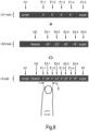
- Fig.8 shows a sketch of an already inventive thought process to achieve a particularly compact LED chain electronics LK-add.
- the LED chain electronics LK-1 and LK-2 are pulled apart slightly and the positions of the adjustment fields E2-1 to E2-5 of the LED chain electronics LK-2 are offset along the longitudinal extension L so that there is an imaginary combined, with respect to the adjustment fields E1-1 to E1-5 and E2-1 to E2-5 nested LED chain electronics LK-add results.
- the combined LED chain electronics LK-add has the same fields 101, 102, E1-1 to E1-4 and E2-1 to E2-4 as the LED chain electronics LK-1 and LK-2 and a combination of the LEDs -Chain electronics LK-1 and LK-2 identically designated setting fields E1-5 and E2-5 to a combination field KF.
- the setting fields E1-1 to E1-4 and E2-1 to E2-4 now alternate in the longitudinal direction.
- the combined LED chain electronics LK-add takes up noticeably less space than the two LED chain electronics LK-1 and LK-2.
- the setting fields E1-1 to E1-4 and E2-1 to E2-4 are now so close together that several of them are within the typical finger contact width B and therefore reliable operation according to the in Figures 6 and 7 described method is no longer available.
- the clarity is reduced due to the close and alternating position of the setting fields E1-1 to E1-4 and E2-1 to E2-4.
- Fig.1 shows a front view and thus also a top view of its operating surfaces, a sketch of a door 1 of a refrigerator 2 with an operating device arranged on the outside in the form of an LED chain electronics 3 according to a first exemplary embodiment.
- the LED chain electronics 3 have a user interface 4 and operating electronics 5 that are not visible to the user underneath.
- the backlit control panels SF1, SF2, E1-1 to E1-4, E2-1 to E2-4 and KF of the LED chain electronics 3 arranged in a row can largely correspond to the arrangement of the control panels of the LED chain electronics LK-add.
- the analogously positioned fields SF1 and SF2 are now touch-sensitive selection fields.
- the operating electronics 5 are set up for a different operation (eg programmed or wired) than in the case of the LED chain electronics LK-add.
- the LED chain electronics 3 here has two control lines BS-1 and BS-2, with the first control line BS-1 being assigned the control panels SF1, E1-1 to E1-4 and KF and the second control line BS-2 being assigned the SF2, E2-1 to E2-4 and KF are assigned.
- the two operating lines BS-1 and BS-2 thus differ in their selection fields SF1 and SF2 and in their exclusive setting fields E1-1 to E1-4 and E2-1 to E2-4. But they have one combo box KF in common.
- the setting fields E1-1 to E1-4 or E2-1 to E2-4 of the two operating lines are arranged alternately next to each other.
- the first control line BS-1 is provided for setting a target cooling temperature of a refrigerator compartment of the cooling device 2 and the second control line BS-2 with the control panels SF2, E2-1 to E2-4 and KF for setting a target cooling temperature of a freezer compartment .
- the control panels SF1, SF2, E1-1 to E1-4, E2-1 to E2-4 and KF are assigned respective physical touch fields 6, which are not visible to a user.
- Each of the control panels SF1, SF2, E1-1 to E1-4, E2-1 to E2-4 and KF is assigned a different optical mask through which the respective control panel SF1, SF2, E1-1 to E1-4, E2 -1 to E2-4 and KF light information about its function can be emitted.
- the touch fields 6 assigned to the selection fields SF1 and SF2 and the combination field KF along the longitudinal extension L are each as wide as the typical finger contact width B.
- the setting fields E1-1 to E1-4 and E2-1 to E2-4 are noticeably shorter.
- a distance dA between next-but-one adjacent setting fields E1-1 to E1-4 or E2-1 to E2-4 of the same operating line BS-1, BS-2 is equal to or greater than the typical finger contact width B, as shown here using setting fields E1 -1 and E1-3 shown.
- a distance dB between adjacent setting fields E1-1 to E1-4 or E2-1 to E2-4 of the same operating line BS-1, BS-2 is smaller than the typical finger contact width B, as shown here using the setting fields E2-1 and E2-2 shown.
- the associated setting fields E1-1 to E1-4 or E2-1 to E2-4 of the same operating line BS-1 or BS-2 are activated for selection by a user, while the setting fields E2- 1 to E2-4 or E1-1 to E1-4 of the respective other control line BS-2 or BS-1 can be deactivated, as explained in more detail below.
- the combination field KF belongs to both operating lines BS-1 and BS-2, it is or remains activated when both selection fields SF1, SF2 are actuated.
- Activations of the control panels SF1, SF2, E1-1 to E1-4, E2-1 to E2-4 and KF are recognized by means of the operating electronics 5.
- the operating electronics 5 are also set up to trigger at least one associated action if the associated control panel BS-1, BS-2 was selectable when operated by a user.
- Fig.2 shows a front view of a sketch of the LED chain electronics 3 in a first state, namely the waiting or standby state.
- the standby state is assumed, for example, when a user has not operated the LED chain electronics 3 for some time.
- the selection fields SF1 and SF2 are selectable for operation by a user and are dimly lit.
- the other control panels E1-1 to E1-4, E2-1 to E2-4 and KF are deactivated and therefore do not light up and cannot be actuated selectable. If a user presses on the non-user-selectable control panels E1-1 to E1-4, E2-1 to E2-4 and KF, the actuation is recognized by the operating electronics 5, but no associated or linked action is triggered.
- control panels that are not illuminated are not visible to a user compared to the background of the user interface 4 .
- the operating electronics 5 If a user presses his finger F on one of the selectable selection fields SF1 and SF2 (here for example on the selection field SF1, as indicated by the wide arrow), this is recognized by the operating electronics 5 . The operating electronics 5 then causes this selection field SF1 to be brightly backlit, as in Fig.3 shown. Since the other selection field SF2 remains user-selectable but is currently not selected, it remains dimly backlit. In particular, the state now exists in which the target temperature value in the cooling part can be set.
- the operating electronics 5 When the selection field SF1 is actuated, the operating electronics 5 also activate the control panels E1-1 to E1-4 and KF belonging to the same operating line BS-1, ie backlit and switched for selection by a user.
- the control panels E1-1, E1-3, E1-4 and KF are dimly backlit because the actions or functions/setting values linked to them are not currently set on cooling device 2.
- the setting field E1-2 is brightly backlit, since the setting value associated with it, namely the target temperature value of 4° C. in the cooling part, is currently set on the cooling device 2 .
- a user wants to change the target temperature value or effect rapid cooling, he can select one of the other control panels E1-1, E1-3, E1-4 or KF by actuation (touching, pressing, etc.).
- this control panel E1-1, E1-3, E1-4 or KF is switched on and the associated action (eg a change in the setpoint temperature value or a start of the rapid cooling) is triggered.
- the setting field E1-2 which was previously switched to being brightly lit, is switched to being dimly lit.
- the triggering of an action by the LED chain electronics 3 can include reporting a corresponding actuation to a central control device of the cooling device 2, which then changes over the cooling operation of the cooling part as an action.
- the other selection field SF2 is actuated within the specified period of time, it is brightly backlit, while the selection field SF1 is only weakly backlit, as in Fig.4 shown.
- the setting fields E1-1 to E1-4 assigned to the first operating line BS-1 are deactivated and the setting fields E1-1 to E1-4 assigned to the second operating line BS-2 are activated, the setting field E1-3 shining brightly here, for example, if the target temperature of the freezer compartment is currently set at -20°C.
- the combination field KF remains backlit. In particular, the state now exists in which the set temperature value in the freezer compartment can be set.
- non-selectable setting fields E-1 to E2-4 or E1-1 to E1-4 are not backlit, they do not appear optically either, so that the selectable setting fields E1-1 to E1-4 or E2 -1 to E2-4 are clearly arranged and are therefore easily distinguishable optically.
- Fig.5 shows a front view of a sketch of the door 2 of the refrigerator 1 with an LED chain electronics 7 according to a second embodiment of the invention instead of the LED chain electronics 3.
- the masks of the LED chain electronics 7 are arranged analogously to the masks of the LED chain electronics 3, and the associated control panels SF1, SF2, E1-1 to E1-4, E2-1 to E2-4 and KF are backlit as in the LED chain electronics 3.
- two adjacent setting fields E1-1, E2-1; E1-2, E2-2, etc. of different operating lines BS-1, BS-2 each have a common one Touch field 8 assigned. If one of the selection fields SF1 or SF2 is actuated, the control panels E1-1 to E1-4 or E2-1 to E2-4 assigned to the operating lines BS-1 or BS-2 light up, as in the case of the LED chain electronics 3 .
- the operating electronics 10 are set up to interpret the actuation of a touch field 8 as an actuation of the control panel E1-1 to E1-4 or E2-1 to E2-4 associated with the selected control line BS-1 or BS-2.
- both selection fields SF1 and SF2 have a common touch field 10 behind them. A user can toggle between these to select a desired selection field SF1 and SF2: for example, in the standby state, the lighting information “cooler” or “freezer” assigned to the selection fields SF1 and SF2 only lights up weakly.
- the selection field SF1 with the associated setting fields E1-1 to E1-4 and the combination field KF is activated for selection, analogously to the LED Chain electronics 3.
- the light information is also switched to "cooler” and brightly lit. The user can now select or activate the setting fields E1-1 to E1-4 and the combination field KF.
- the selection field SF2 with the associated setting fields E2-1 to E2-4 and the combination field KF is activated for selection, analogously to the LED chain electronics 3.
- the lighting information " freezer” is switched brightly lit, while the lighting information "cooler” is switched dimly lit.
- the user can now select or activate the setting fields E2-1 to E2-4 and the combination field KF.
- control line BS-1 is activated again, if it is pressed again, the control line BS-2 is activated again, etc.
- a user can then switch through or “toggle” between the selection fields one after the other by actuating the touch field several times.
- the currently selected selection field is indicated to a user by a brighter glow.
- several selection fields are provided as control panels that can be switched through one after the other.
- the invention can thus also be extended to three or more operating lines in an analogous manner.
- the number of setting fields for different operating lines can generally differ.
- the LED chain electronics can, for example, be attached horizontally or vertically to the household appliance. In the case of a vertical alignment, the light information is rotated by 90°, in contrast to the exemplary embodiments illustrated in the figures.
- toggleable selection fields as shown in the LED chain electronics 7 can be combined with setting fields as shown in the chain electronics 3 .
- "a”, “an” etc. can be understood as a singular or a plural number, in particular in the sense of “at least one” or “one or more” etc., as long as this is not explicitly excluded, e.g. by the expression “exactly a” etc.
- a numerical specification can also include exactly the specified number as well as a usual tolerance range, as long as this is not explicitly excluded.
Description
Die Erfindung betrifft eine LED-Kettenelektronik für ein Haushaltsgerät, mit mehreren berührungsempfindlichen, in einer Reihe angeordneten Bedienfeldern. Die Erfindung betrifft ferner ein Haushaltsgerät mit mindestens einer solchen LED-Kettenelektronik. Die Erfindung betrifft auch ein Verfahren zum Betreiben einer LED-Kettenelektronik. Die Erfindung ist anwendbar auf Haushaltskühlgeräte, speziell mit einem Kühlteil und einem Gefrierteil.The invention relates to LED chain electronics for a household appliance, with a plurality of touch-sensitive control panels arranged in a row. The invention also relates to a household appliance with at least one such LED electronic chain. The invention also relates to a method for operating LED chain electronics. The invention is applicable to household refrigeration appliances, especially with a refrigerator part and a freezer part.
Zur Bedienung von Kühlschränken sind an einer Außenseite einer Kühlschranktür angeordnete Bedienfelder bekannt. Dabei ist es gewünscht, die zugehörige Fläche gering zu halten, ohne eine Bedienerfreundlichkeit zu verringern. Dies kann beispielsweise durch berührungsempfindliche TFT-Displays umgesetzt werden, bei denen sich die zu den Bedienfeldern gehörige angezeigte Information variabel einstellen lässt. Jedoch haben TFT-Displays den Nachteil, dass sie nach wie vor sehr teuer sind.Control panels arranged on the outside of a refrigerator door are known for operating refrigerators. In this case, it is desirable to keep the associated area small without reducing user-friendliness. This can be implemented, for example, by touch-sensitive TFT displays, in which the information displayed on the control panels can be variably adjusted. However, TFT displays have the disadvantage that they are still very expensive.
Zur Nutzung als Bedienfelder sind auch sog. LED-Kettenelektroniken bekannt. Dabei handelt es sich typischerweise um längliche oder bandförmige Streifen mit in Längserstreckung in Reihe angeordneten berührungsempfindlichen Bedienfeldern (auch als "Touchfelder" oder "Direct Touch"-Bedienfelder bezeichnet). Die Bedienfelder können als berührungsempfindliche Schichten oder Schichtstapel ausgebildet sein, die beispielsweise als induktive Näherungsschalter, kapazitive Näherungsschalter oder elektrische Kontaktschalter wirken. Die Bedienfelder sind mittels mindestens einer LED individuell hinterleuchtbar und beispielsweise mit einer Maske versehen, um jedem Bedienfeld eine fest vorgegebene Leuchtinformation zuzuordnen, z.B. in Form von Buchstaben, Zahlen, Symbolen usw. Anders als bei einem TFT-Display kann also bei einer LED-Kettenanzeigen jede Position nur mit einem bestimmten Anzeigefeld belegt werden. Als Träger einer LED-Kettenelektronik dient eine - steife oder biegsame - Leiterplatte oder Platine, auf der zusätzlich zu den berührungsempfindlichen Bedienfeldern und LEDs eine Schaltung oder Elektronik zur Auswertung der Bedienfelder auf Berührung, Ansteuerung der LEDs und ggf. Auslösen mindestens einer Aktion bei Berührung der Bedienfelder vorhanden ist.So-called LED chain electronics are also known for use as control panels. These are typically elongate or strip-shaped strips with touch-sensitive control panels (also referred to as "touch panels" or "direct touch" control panels) arranged in a row in the longitudinal direction. The control panels can be designed as touch-sensitive layers or layer stacks that act, for example, as inductive proximity switches, capacitive proximity switches or electrical contact switches. The control panels can be individually backlit using at least one LED and, for example, are provided with a mask in order to allocate fixed lighting information to each control panel, e.g. in the form of letters, numbers, symbols, etc. In contrast to a TFT display, an LED chain display can be used each position can only be occupied by a specific display field. A - rigid or flexible - printed circuit board or circuit board serves as the carrier of an LED chain electronics, on which, in addition to the touch-sensitive control panels and LEDs, a circuit or electronics for evaluating the control panels for touch, controlling the LEDs and, if necessary, triggering at least one action when touching the control panels is present.
Die
Die
Die
Die
Die
Typisch für eine LED-Kettenelektronik ist ein ausreichend großer Abstand zwischen den einzelnen Bedienfeldern, um eine ergonomische Bedienbarkeit zu gewährleisten. Hierfür wird bisher pro einstellbarem Betriebsparameter eine eigene LED-Kettenelektronik bereitgestellt, was bei mehreren einstellbaren Betriebsparametern einen immer noch großen Flächenbedarf zur Folge hat, und zwar entweder durch Erzeugung einer Bedienvorrichtung als langer Zeile mit mehreren hintereinander angeordneten LED-Kettenelektroniken oder als Anzeigefeld mit mehreren nebeneinander angeordneten LED-Kettenelektroniken. Es ist die Aufgabe der vorliegenden Erfindung, die Nachteile des Standes der Technik zumindest teilweise zu überwinden und insbesondere eine besonders kompakte und dennoch gut bedienbare sowie preiswerte LED-Kettenelektronik bereitzustellen, speziell für ein Haushaltsgerät.A sufficiently large distance between the individual control panels is typical for LED chain electronics in order to ensure ergonomic operability. To date, a separate LED chain electronics has been provided for each adjustable operating parameter, which still requires a large amount of space when there are several adjustable operating parameters, either by creating an operating device as a long line with several LED chain electronics arranged one behind the other or as a display field with several next to each other arranged LED chain electronics. It is the object of the present invention to at least partially overcome the disadvantages of the prior art and in particular to provide a particularly compact and yet easy to use and inexpensive LED chain electronics, especially for a household appliance.
Diese Aufgabe wird gemäß den Merkmalen der unabhängigen Ansprüche gelöst. Vorteilhafte Ausführungsformen sind Gegenstand der abhängigen Ansprüche, der Beschreibung und der Zeichnungen.This object is solved according to the features of the independent claims. Advantageous embodiments are the subject matter of the dependent claims, the description and the drawings.
Die Aufgabe wird gemäß den Merkmalen des unabhängigen Anspruchs gelöst.The object is solved according to the features of the independent claim.
Diese LED-Kettenelektronik ergibt den Vorteil, dass sie bei besonders kompakter Außenform eine hohe Zahl von zuverlässig erkennbaren und betätigbaren Bedienfeldern bereitstellt und dennoch preiswert umsetzbar ist. So kann im Vergleich zu mehreren getrennt angeordneten LED-Kettenelektronik gleicher Funktionalität eine merkliche Verringerung der Grundfläche erreicht werden. Sie kann speziell auch an Stellen positioniert werden, an denen wenig Platz vorhanden ist. Zudem wird eine zeitgemäße Gestaltung mit dezenter Präsenz erreicht. Darüber hinaus ist eine solche LED-Kettenelektronik robust.This LED chain electronics has the advantage that, with a particularly compact external shape, it provides a large number of control panels that can be reliably identified and operated, and can still be implemented inexpensively. In comparison to several separately arranged LED chain electronics with the same functionality, there can be a noticeable reduction of the base area can be achieved. It can also be specifically positioned in places where there is little space. In addition, a contemporary design with a subtle presence is achieved. In addition, such LED chain electronics are robust.
Es ist vorgesehen, dass ein Abstand zwischen übernächst benachbarten Einstellfeldern des gleichen Bedienstrangs (entlang der Längserstreckung der LED-Kettenelektronik) gleich oder größer als eine typische Fingerkontaktbreite ist und ein Abstand zwischen benachbarten Einstellfeldern des gleichen Bedienstrangs kleiner ist als die typische Fingerkontaktbreite. Dadurch wird besonders zuverlässig erreicht, dass eine kompakte Anordnung mit nutzfreundlicher Bedienung bereitgestellt wird. Durch den Abstand zwischen übernächst benachbarten Einstellfeldern des gleichen Bedienstrangs gleich oder größer als eine typische Fingerkontaktbreite wird nämlich erreicht, dass bei aktiviertem Bedienstrang nicht auch dazu benachbarte Einstellfelder anderer Bedienstränge ungewollt betätigt werden. Ist nur in eine Richtung noch ein Einstellfeld des gleichen Bedienstrangs vorhanden, kann die obige Bedingung auch so formuliert werden, dass ein Abstand von der Mitte des Einstellfelds zu dem Rand des benachbarten Einstellfelds des gleichen Bedienstrangs mindestens einer halben Fingerkontaktbreite entspricht. Dadurch, dass ein Abstand zwischen benachbarten Einstellfeldern des gleichen Bedienstrangs kleiner ist als die typische Fingerkontaktbreite, wird eine besonders kompakte Anordnung erreicht. Unter einer "typischen Fingerkontaktbreite" wird eine für einen Finger einer erwachsenen Person typische Ausdehnung einer Kontaktfläche mit der LED-Kettenelektronik entlang deren Längserstreckung bei Betätigung eines Bedienfelds verstanden.It is envisaged that a distance between the next but one adjacent setting fields of the same operating line (along the longitudinal extent of the LED chain electronics) is equal to or greater than a typical finger contact width and a distance between adjacent setting fields of the same operating line is smaller than the typical finger contact width. As a result, it is achieved in a particularly reliable manner that a compact arrangement with user-friendly operation is provided. The distance between the next-but-one setting fields of the same operating line is equal to or greater than a typical finger contact width, which means that when the operating line is activated, adjacent setting fields of other operating lines are not also unintentionally actuated. If there is only one setting field in the same control column in one direction, the above condition can also be formulated in such a way that a distance from the center of the setting field to the edge of the neighboring setting field in the same control column corresponds to at least half a finger contact width. A particularly compact arrangement is achieved because the distance between adjacent setting fields of the same operating line is smaller than the typical finger contact width. A "typical finger contact width" is understood to mean an extension of a contact surface with the LED chain electronics, which is typical for a finger of an adult, along its longitudinal extent when a control panel is actuated.
Die typische Fingerkontaktbreite beträgt zwischen 15 mm und 20 mm.The typical finger contact width is between 15 mm and 20 mm.
Während eine Fingerkontaktbreite von 20 mm am oberen Ende einer mindestens benötigen Breite liegt, sind 15 mm eine untere Grenz der Bedienbarkeit für typische Finger einer erwachsenen Person.While a finger contact width of 20mm is at the high end of a minimum required width, 15mm is a lower limit of operability for typical adult fingers.
Erfindungsgemäß ist jedem Bedienfeld ein jeweiliges Touchfeld zugeordnet ist oder benachbarten Einstellfeldern unterschiedlicher Bedienstränge das gleiche Touchfeld zugeordnet.According to the invention, a respective touch field is assigned to each control panel, or the same touch field is assigned to adjacent setting fields of different operating lines.
Erfindungsgemäß sind mehreren Selektionsfeldern das gleiche oder ein gemeinsames Touchfeld zugeordnet ist und mindestens eines der Selektionsfelder ist durch mehrfaches Betätigen des Touchfelds auswählbar. Ein Nutzer kann dann zwischen den angezeigten Selektionsfeldern durch mehrfaches Betätigen des Touchfelds nacheinander durchschalten oder "toggeln". Dabei wird das aktuell ausgewählte Selektionsfeld einem Nutzer durch helleres Leuchten angezeigt. Im letzteren Fall werden also mehrere Selektionsfelder als nacheinander durchschaltbare oder auswählbare Bedienfelder bereitgestellt.According to the invention, the same or a common touch field is assigned to several selection fields and at least one of the selection fields can be selected by actuating the touch field several times. A user can then switch through or “toggle” one after the other between the displayed selection fields by repeatedly actuating the touch field. The currently selected selection field is indicated to a user by a brighter glow. In the latter case, several selection fields are provided as control panels that can be toggled through or selected one after the other.
Die LED-Kettenelektronik ist so eingerichtet, dass bestimmte nutzerauswählbare Bedienfelder für einen Nutzer sichtbar oder hervorgehoben sichtbar sind und durch direktes Betätigen (z.B. Berühren oder Drücken) eines nutzerauswählbaren Bedienfelds eine zugehörige, insbesondere fest vorgegebene, Funktion oder Aktion ausgelöst werden kann.The LED chain electronics are set up in such a way that certain user-selectable control panels are visible or highlighted for a user and an associated, in particular fixed, function or action can be triggered by directly actuating (e.g. touching or pressing) a user-selectable control panel.
Die LED-Kettenelektronik und damit auch deren Bedienoberfläche ist insbesondere bandförmig geformt, insbesondere geradlinig, aber grundsätzlich z.B. auch gekrümmt, kreisförmig oder freiförmig. Die Bedienfelder sind entsprechend in einer Reihe entlang der Längserstreckung der LED-Kettenelektronik angeordnet, insbesondere sich nicht überlappend.The LED chain electronics and thus also its user interface is in particular in the form of a strip, in particular in a straight line, but in principle also e.g. curved, circular or free-form. The control panels are accordingly arranged in a row along the longitudinal extension of the LED chain electronics, in particular not overlapping.
Dass die Bedienfelder mindestens zwei Selektionsfelder umfassen, bei dessen Betätigung zu einem gleichen Bedienstrang gehörige Einstellfeldern exklusiv durch einen Nutzer auswählbar werden, umfasst insbesondere, dass nur bei Betätigung eines bestimmten Selektionsfelds weitere Bedienfelder der LED-Kettenelektronik (die selbst keine Selektionsfelder sind) zur Auswahl durch einen Nutzer freigeschaltet werden. Dadurch, dass die Bedienfelder mindestens zwei Selektionsfelder umfassen, umfasst die LED-Kettenelektronik auch mindestens zwei Bedienstränge.The fact that the control panels include at least two selection fields, which, when activated, can be used exclusively by a user to select setting fields belonging to the same operating line, means in particular that further control panels of the LED chain electronics (which themselves are not selection fields) can only be selected by pressing a specific selection field be activated for a user. Because the control panels include at least two selection fields, the LED chain electronics also includes at least two control lines.
Dabei wird unter einen "Bedienstrang" ein Satz von Bedienfeldern umfassend ein Selektionsfeld und die bei Betätigung dieses Selektionsfelds nutzerauswählbaren Bedienfelder, die selbst keine Selektionsfelder darstellen, verstanden. Ein Bedienstrang umfasst mindestens ein exklusiv auswählbares Einstellfeld und kann auch mindestens ein wie weiter unten näher beschriebenes Kombinationsfeld umfassen. Die Bedienfelder eines Bedienstrangs stellen eine echte Teilmenge aller Bedienfelder der LED-Kettenelektronik dar. Unterschiedliche Bedienstränge unterscheiden sich in mindestens einem Bedienfeld, insbesondere in ihren Einstellfeldern. Es ist eine Weiterbildung, dass jeder der Bedienstränge mehrere Einstellfelder aufweist. Ein Einstellfeld dient zum Einstellen eines zugehörigen Geräts, insbesondere Haushaltsgeräts.A "service line" is understood to mean a set of control panels comprising a selection field and the control panels that can be selected by the user when this selection field is actuated and that do not themselves represent any selection fields. A service line includes at least one setting field that can be selected exclusively and can also include at least one combo box, as described in more detail below. The control panels of a control line represent a real subset of all control panels of the LED chain electronics. Different control lines differ in at least one control panel, in particular in their setting fields. In a further development, each of the operating lines has a number of setting fields. A setting field is used to set an associated device, in particular a household appliance.
Dass die Einstellfelder unterschiedlicher Bedienstränge wechselweise nebeneinander angeordnet sind, umfasst insbesondere, dass sich Einstellfelder unterschiedlicher Bedienstränge entlang der bandförmigen Längserstreckung der LED-Kettenelektronik abwechseln. Liegen mehr als zwei Bedienstränge vor, können sich die Einstellfelder in immer der gleichen Reihenfolge abwechseln.The fact that the setting fields of different operating lines are arranged alternately next to one another includes, in particular, that setting fields of different operating lines alternate along the strip-shaped longitudinal extension of the LED chain electronics. If there are more than two operating lines, the setting fields can always alternate in the same order.
Da jedes Bedienfeld der LED-Kettenelektronik individuell hinterleuchtbar ist, können die jeweiligen Helligkeiten individuell eingestellt werden. Die Helligkeit umfasst mindestes drei unterschiedliche Helligkeitsniveaus: eine geringste Helligkeit, mittels der aktuell nicht nutzerauswählbare Einstellfelder hinterleuchtet werden, eine mittlere Helligkeit, mittels der aktuell nutzerauswählbare, aber nicht ausgewählte Einstellfelder hinterleuchtet werden und eine höchste Helligkeit, mittels der aktuell ausgewählte Einstellfelder hinterleuchtet werden. Dadurch wird der Vorteil erreicht, dass nutzerauswählbare und nutzerausgewählte Einstellfelder optisch deutlich von nicht auswählbaren Einstellfeldern unterscheidbar sind und auch untereinander deutlich unterscheidbar sind. Dies wiederum erhöht eine Bedienbarkeit erheblich.Since each control panel of the LED chain electronics can be individually backlit, the respective brightness can be set individually. The brightness comprises at least three different brightness levels: a lowest brightness, by means of which control fields that are not currently user-selectable are backlit, a medium brightness, by means of which control fields which are currently user-selectable but not selected are backlit, and a maximum brightness, by means of which control fields which are currently selected are backlit. This achieves the advantage that user-selectable and user-selected setting fields are optically clearly distinguishable from non-selectable setting fields and are also clearly distinguishable from one another. This in turn increases operability considerably.
Es ist eine Ausgestaltung, dass aktuell nicht nutzerauswählbare Bedienfelder nicht leuchten. Dadurch wird eine Bedienbarkeit für einen Nutzer noch weiter erhöht. In diesem Fall existieren also nur die Helligkeitsniveaus "dunkel", "schwach" und "hell", o.ä.It is an embodiment that control panels that are not currently user-selectable are not illuminated. This further increases usability for a user. In this case, only the brightness levels "dark", "weak" and "bright" or similar exist.
Es ist eine Weiterbildung, dass die Schaltung oder Elektronik der LED-Kettenelektronik dazu eingerichtet ist, die Bedienfelder auf eine Betätigung zu überwachen, und dazu eingerichtet ist, bei Betätigung eines nutzerauswählbaren Bedienfelds eine diesem Bedienfeld zugehörige Aktion auszulösen. Die ausgelöste Aktion kann z.B. eine Änderung eines Helligkeitsniveaus des betätigten und/oder anderer Bedienfelder umfassen und/oder kann eine Aussendung einer Nachricht, dass ein bestimmtes Bedienfeld betätigt worden ist, an eine externe Einheit (z.B. an eine Steuereinrichtung eines Haushaltsgeräts) umfassen.In one development, the circuitry or electronics of the LED chain electronics is set up to monitor the control panels for actuation and is set up to trigger an action associated with this control panel when a user-selectable control panel is actuated. The triggered action can include, for example, changing a brightness level of the operated and/or other control panels and/or can include sending a message that a specific control panel has been operated to an external unit (eg to a control device of a household appliance).
Es ist eine Ausgestaltung, dass den Selektionsfeldern selektionsunabhängig jeweils mindestens eine typische Fingerkontaktbreite zugeordnet ist. Dadurch wird sichergestellt, dass sich die Selektionsfelder immer - d.h., auch wenn ein anderes Selektionsfeld aktuell ausgewählt ist - einer typischen Fingerkontaktbreite zugeordnet ist. Diese Zuordnung kann dadurch erreicht werden, dass ein Abstand zu benachbarten Selektionsfeldern entsprechend groß ist und/oder das Selektionsfeld selbst entsprechend breit ist. Dies kann auch so ausgedrückt werden, dass ein Abstand von der Mitte des Selektionsfelds zu dem Rand eines benachbarten Selektionsfelds mindestens einer halben Fingerkontaktbreite entspricht.In one embodiment, at least one typical finger contact width is assigned to the selection fields, independently of the selection. This ensures that the selection fields are always assigned to a typical finger contact width, i.e. even if another selection field is currently selected. This assignment can be achieved in that a distance to adjacent selection fields is correspondingly large and/or the selection field itself is correspondingly wide. This can also be expressed in such a way that a distance from the center of the selection field to the edge of an adjacent selection field corresponds to at least half a finger contact width.
Es ist eine Weiterbildung, dass die Selektionsfelder immer zumindest schwach hinterleuchtet sind, also im normalen Betrieb immer hinterleuchtet sind oder nie dunkelgeschaltet sind.It is a further development that the selection fields are always at least weakly backlit, ie are always backlit in normal operation or are never switched off.
Es ist eine Ausgestaltung, dass die Einstellfelder zumindest eines gleichen Bedienstrangs dazu eingerichtet sind, verschiedene Werte eines bestimmten Betriebsparameters auszuwählen. So lässt sich eine besonders einfache Benutzerführung und Bedienbarkeit erreichen. Mögliche Betriebsparameters können beispielsweise eine Temperatur, eine Feuchtigkeit, eine Leistungsstufe, usw. umfassen. Dass die Einstellfelder entsprechend eingerichtet sind, kann z.B. umfassen, dass deren Masken und damit die bei Hinterleuchtung durch einen Nutzer erkennbare Lichtinformation entsprechend ausgestaltet ist. So können im Fall eines Betriebsparameters in Form einer Kühltemperatur eines Kühlteils eines Kühlschranks die Lichtinformationen als Temperaturwerte "2°C", "4°C", "6°C" und "8°C" geformt sein.In one configuration, the setting fields of at least one of the same operating line are set up to select different values of a specific operating parameter. In this way, particularly simple user guidance and operability can be achieved. Possible operating parameters can include a temperature, a humidity, a power level, etc., for example. The fact that the setting fields are set up accordingly can include, for example, that their masks and thus the light information recognizable by a user when backlit is designed accordingly. Thus, in the case of an operating parameter in the form of a cooling temperature of a refrigerator part of a refrigerator, the light information can be shaped as temperature values "2°C", "4°C", "6°C" and "8°C".
Es ist eine Weiterbildung, dass die Selektionsfelder bei Hinterleuchtung eine Lichtinformation aufweisen oder abstrahlen, welche auf den durch die Einstellfelder dieses Bedienstrangs einstellbaren Betriebsparameter hinweist. So kann im Fall eines Betriebsparameters in Form einer Kühltemperatur eines Kühlteils eines Kühlschranks die Lichtinformation des zugehörigen Selektionsfelds als "Kühlteil", "Cooler", usw. dargestellt werden.In a further development, the selection fields have or emit light information when they are backlit, which indicates the operating parameters that can be set using the setting fields of this operating line. In the case of an operating parameter in the form of a cooling temperature of a refrigerator part of a refrigerator, the light information of the associated selection field can be displayed as "refrigerator part", "cooler", etc.
Es ist eine Ausgestaltung, dass die LED-Kettenelektronik zusätzlich mindestens ein Bedienfeld in Form eines Kombinationsfelds aufweist, das für mehrere ausgewählte Bedienstränge nutzerauswählbar ist oder mehreren Bediensträngen zugeordnet ist. Dadurch brauchen im mehreren Bediensträngen vorkommende gleiche Bedienfelder nur einmal dargestellt zu werden, wodurch sich eine weitere Platz- und Kostenreduktion ergibt. Beim Umschalten zwischen zwei Bediensträngen, die das gleiche Kombinationsfeld aufweisen, kann das Kombinationsfeld hinterleuchtet bleiben oder alternativ kurz deaktiviert und dann wieder aktiviert werden.In one embodiment, the LED chain electronics additionally have at least one control panel in the form of a combo box, which can be selected by the user for a number of selected control lines or is assigned to a number of control lines. Through this the same control panels occurring in several control lines need only be displayed once, which results in a further reduction in space and costs. When switching between two operating lines that have the same combo box, the combo box can remain backlit or, alternatively, be deactivated briefly and then activated again.
Es ist eine Weiterbildung, dass die LED-Kettenelektronik als eine Bedienvorrichtung für ein Haushaltsgerät vorgesehen oder eingerichtet ist.In one development, the LED chain electronics are provided or set up as an operating device for a household appliance.
Die Aufgabe wird auch gelöst durch ein Haushaltsgerät, das mindestens eine LED-Kettenelektronik wie oben beschrieben aufweist. Das Haushaltsgerät kann analog zu der LED-Kettenelektronik ausgebildet werden und weist die gleichen Vorteile auf.The object is also achieved by a household appliance that has at least one LED electronic chain as described above. The household appliance can be designed analogously to the LED chain electronics and has the same advantages.
Es ist eine Ausgestaltung, dass das Haushaltsgerät ein Kühlgerät ist. Dadurch wird der Vorteil erreicht, dass aufgrund er geringen Baugröße der LED-Kettenelektronik eine geringe Isolationsschwächung auftritt.In one configuration, the household appliance is a cooling appliance. This achieves the advantage that due to the small size of the LED chain electronics, there is little weakening of the insulation.
Es ist eine Ausgestaltung, dass für den Fall, dass das Haushaltsgerät ein Kühlgerät mit einem Kühlteil und einem Gefrierteil umfasst, die den Bediensträngen zugeordneten Betriebsparameter eine Temperatur in dem Kühlteil und eine Temperatur in dem Gefrierteil umfassen. Dadurch lassen sich die für einen Nutzer wichtigsten Einstellungen mittels einer einzigen LED-Kettenelektronik wie oben beschrieben vornehmen. Es ist eine Weiterbildung, dass die LED-Kettenelektronik mindestens ein Kombinationsfeld aufweist, das zur Einstellung entsprechender Funktionen oder Werte für beide Teile auswählbar ist, z.B. mindestens ein Kombinationsfeld "Super", "Eco", usw.In one embodiment, if the household appliance includes a refrigerator with a refrigerator part and a freezer part, the operating parameters assigned to the operating lines include a temperature in the refrigerator part and a temperature in the freezer part. As a result, the most important settings for a user can be made using a single LED chain electronics as described above. It is a further development that the LED chain electronics has at least one combo box that can be selected for setting corresponding functions or values for both parts, e.g. at least one "Super", "Eco", etc. combo box.
Jedoch kann das Haushaltsgerät auch ein beliebiges anderes Haushaltsgerät sein, beispielsweise ein Gargerät, ein Spülgerät, ein Wäschebehandlungsgerät oder ein anderes Haushalts-Großgerät. Das Haushaltsgerät kann aber auch ein Haushalts-Kleingerät wie eine Kaffeemaschine usw. sein. Das Haushaltsgerät ist insbesondere ein Küchengerät.However, the household appliance can also be any other household appliance, for example a cooking appliance, a dishwasher, a laundry treatment appliance or another large household appliance. However, the household appliance can also be a small household appliance such as a coffee machine, etc. The household appliance is in particular a kitchen appliance.
Es ist eine Weiterbildung, dass das Haushaltsgerät mindestens einen Behandlungsraum (z.B. einen Kühlraum, Gefrierraum, Garraum, Spülraum, Wäschetrommel usw.) aufweist und die LED-Kettenelektronik in einer den Behandlungsraum verschließenden Tür angeordnet ist, insbesondere in oder an einer Außenseite der Tür. Die LED-Kettenelektronik kann z.B. horizontal oder vertikal ausgerichtet sein.It is a further development that the household appliance has at least one treatment room (e.g. a cold room, freezer room, cooking room, dishwashing room, laundry drum, etc.) and the LED chain electronics are arranged in a door closing the treatment room, in particular in or on an outside of the door. The LED chain electronics can be aligned horizontally or vertically, for example.
Die Aufgabe wird außerdem gelöst durch ein Verfahren zum Betreiben einer LED-Kettenelektronik wie oben beschrieben, bei dem
- die Bedienfelder auf ihre Betätigung überwacht werden,
- falls eine Betätigung oder Auswahl eines Selektionsfelds erkannt wird, die zu dem gleichen Bedienstrang zugehörigen Einstellfelder leuchtend zur Auswahl aktiviert oder geschaltet werden und die übrigen Einstellfelder unter Dunkelschaltung deaktiviert werden und
- falls eine Betätigung eines auswählbaren oder aktiven Einstellfelds erkannt wird, dieses hell leuchtend eingestellt wird und eine diesem Einstellfeld zugeordnete Aktion ausgelöst wird.
- the control panels are monitored for their operation,
- if an actuation or selection of a selection field is detected, the setting fields associated with the same operating line are activated or switched for selection and the remaining setting fields are deactivated under dark switching and
- if an actuation of a selectable or active setting field is detected, this is set to be brightly lit and an action associated with this setting field is triggered.
Das Verfahren kann analog zu der LED-Kettenelektronik und/oder dem Haushaltsgerät ausgebildet werden und weist die gleichen Vorteile auf.The method can be designed analogously to the LED chain electronics and/or the household appliance and has the same advantages.
Dass zu einem Selektionsfeld zugehörige Einstellfelder leuchtend zur Auswahl aktiviert (oder auch nur einfach "aktiviert" werden), umfasst, dass diese Einstellfelder für einen Nutzer erkennbar hinterleuchtet werden und für sie bei Nutzerbetätigung eine Aktion ausgelöst werden kann. Die aktivierten Einstellfelder können in einer Variante schwach leuchten, falls der Betriebs des Haushaltsgeräts durch die jeweils zugehörige Aktion geändert oder variiert wird, und hell leuchten, falls das Haushaltsgerät aktuell bereits entsprechend der zugehörigen Aktion betrieben wird. Beispielsweise kann für einen Kühlschrank bei Aktivierung eines zu einem Kühlteil oder einem Gefrierteil gehörigen Selektionsfelds die zugehörige Kühltemperatur eingestellt werden. Dazu leuchtet dasjenige Einstellfeld, das der aktuell eingestellten Kühltemperatur entspricht, hell auf, während die anderen Einstellfelder nur schwach leuchten.The fact that setting fields associated with a selection field are brightly activated for selection (or simply "activated") means that these setting fields are backlit in a way that is recognizable to a user and an action can be triggered for them when the user presses them. In one variant, the activated setting fields can glow dimly if the operation of the household appliance is changed or varied by the respective associated action, and glow brightly if the household appliance is currently already being operated according to the associated action. For example, the associated cooling temperature can be set for a refrigerator when a selection field belonging to a refrigerator part or a freezer part is activated. To do this, the setting field that corresponds to the currently set cooling temperature lights up brightly, while the other setting fields only light up dimly.
Es ist eine Ausgestaltung, dass mit Betätigung eines Selektionsfelds dieses hell leuchtend eingestellt wird, während das mindestens eine andere Selektionsfeld schwach leuchtend eingestellt wird.In one configuration, when a selection field is actuated, it is set to be brightly lit, while the at least one other selection field is set to be faintly lit.
Auch ist es eine Weiterbildung, dass das Haushaltsgerät al solches dazu eingerichtet ist, mit Betätigung eines auswählbaren Einstellfelds oder - falls vorhanden - Kombinationsfelds eine entsprechende Aktion oder Funktion auszulösen, z.B. eine Solltemperatur zu ändern, einen Schnellkühlvorgang zu starten usw. Beispielsweise kann dazu von einer Steuereinrichtung des Haushaltsgeräts eine Nachricht von der LED-Kettenelektronik empfangen worden sein, dass ein bestimmtes auswählbares Einstellfeld oder- falls vorhanden - Kombinationsfeld betätigt worden ist und beruhend daraus eine Steuerung des Haushaltsgeräts anpassen.It is also a development that the household appliance is set up as such to trigger a corresponding action or function by pressing a selectable setting field or - if available - combo box, e.g. changing a setpoint temperature, starting a quick cooling process, etc Controller of the household appliance have received a message from the LED chain electronics that a specific selectable setting field or - if available - combo box has been pressed and based on it adjust a control of the household appliance.
Die oben beschriebenen Eigenschaften, Merkmale und Vorteile dieser Erfindung sowie die Art und Weise, wie diese erreicht werden, werden klarer und deutlicher verständlich im Zusammenhang mit der folgenden schematischen Beschreibung eines Ausführungsbeispiels, das im Zusammenhang mit den Zeichnungen näher erläutert wird.
- Fig.1
- zeigt in Frontansicht eine Skizze einer Tür eines Kühlschranks mit einer erfindungsgemäßen LED-Kettenelektronik gemäß einem ersten Ausführungsbeispiel;
- Fig.2
- zeigt in Frontansicht eine Skizze der LED-Kettenelektronik gemäß dem ersten Ausführungsbeispiel in einem ersten Zustand;
- Fig.3
- zeigt in Frontansicht eine Skizze der LED-Kettenelektronik gemäß dem ersten Ausführungsbeispiel in einem zweiten Zustand;
- Fig.4
- zeigt in Frontansicht eine Skizze der LED-Kettenelektronik gemäß dem ersten Ausführungsbeispiel in einem dritten Zustand;
- Fig.5
- zeigt in Frontansicht eine Skizze einer Tür eines Kühlschranks mit einer erfindungsgemäßen LED-Kettenelektronik gemäß einem zweiten Ausführungsbeispiel;
- Fig.6
- zeigt eine Skizze von zwei in Draufsicht auf eine Bedienoberfläche hintereinander angeordneten nicht erfindungsgemäßen LED-Kettenelektroniken;
- Fig.7
- zeigt eine Skizze von zwei in Draufsicht auf eine Bedienoberfläche nebeneinander angeordneten nicht erfindungsgemäßen LED-Kettenelektroniken; und
- Fig.8
- zeigt eine Skizze eines Gedankenablaufs zum Erlangen einer besonders kompakten LED-Kettenelektronik.
- Fig.1
- shows a front view of a sketch of a door of a refrigerator with an LED chain electronics according to the invention according to a first embodiment;
- Fig.2
- shows a sketch of the LED chain electronics according to the first exemplary embodiment in a first state in a front view;
- Fig.3
- shows a front view sketch of the LED chain electronics according to the first embodiment in a second state;
- Fig.4
- shows a sketch of the LED chain electronics according to the first exemplary embodiment in a third state in a front view;
- Fig.5
- shows a front view of a sketch of a door of a refrigerator with an LED chain electronics according to the invention according to a second embodiment;
- Fig.6
- shows a sketch of two LED chain electronics not according to the invention arranged one behind the other in a plan view of a user interface;
- Fig.7
- shows a sketch of two LED chain electronics not according to the invention arranged next to one another in a plan view of a user interface; and
- Fig.8
- shows a sketch of a thought process for achieving a particularly compact LED chain electronics.
Eine erste LED-Kettenelektronik LK-1 ist zur Einstellung einer Soll-Kühltemperatur des Kühlteils vorgesehen und weist dazu in Längserstreckung L hintereinander angeordnet ein Anzeigefeld 102, vier Einstellfelder E1-1 bis E1-4 zum Einstellen zugehöriger Sollwerte und ein Einstellfeld E1-5 zum Einstellen einer Sonderfunktion zum besonders schnellen Abkühlen des Kühlteils auf. Die Felder 101, E1-1 bis E1-4 und E1-5 sind hinterleuchtet und stellen dann durch entsprechende Maskierungen Leuchtinformation dar, z.B. das Anzeigefeld 101 die Leuchtinformation "cooler", um einen Nutzer darauf hinzuweisen, dass diese LED-Kettenelektronik LK-1 zum Einstellen der Soll-Kühltemperatur des Kühlteils dient, die Einstellfelder E1-1 bis E1-4 die zugeordneten Soll-Temperaturwerte und das Einstellfeld E1-5 die Leuchtinformation "super". Zumindest die Einstellfelder E1-1 bis E1-5 sind als "Direct Touch"-Felder ausgebildet, so dass bei deren Betätigung die damit verknüpfte Funktion oder Aktion ausgelöst wird.A first electronic chain of LEDs LK-1 is provided for setting a target cooling temperature of the refrigerator compartment and has a
Speziell können die Felder 101, E1-1 bis E1-4 und E1-5 immer schwach hinterleuchtet sein oder schwach leuchten, falls der Betrieb des Kühlgeräts durch die jeweils zugehörige Aktion geändert oder variiert wird, und hell leuchten, falls das Kühlgerät aktuell bereits entsprechend der zugehörigen Aktion betrieben wird. Ist das Kühlgerät beispielsweise bereits so eingestellt, dass seine Soll-Kühltemperatur auf 4° eingestellt ist, leuchtet wie gezeigt nur das zugehörige Einstellfeld E1-2 hell. Würde ein Nutzer nun z.B. das mit der Leuchtinformation "6°" versehene Einstellfeld E1-3 drücken, würde die Soll-Kühltemperatur auf 6° umgestellt werden, usw.Specifically, fields 101, E1-1 through E1-4, and E1-5 may always be dimly backlit or dimly lit if the operation of the chiller is modified or varied by the associated action, and brightly lit if the chiller is currently already doing so the associated action is operated. If, for example, the cooling device is already set so that its target cooling temperature is set to 4°, only the associated setting field E1-2 lights up brightly, as shown , the target cooling temperature would be changed to 6°, etc.
Eine zweite LED-Kettenelektronik LK-2 ist analog zur Einstellung einer Soll-Kühltemperatur des Gefrierteils eingerichtet, und zwar mit einem Anzeigefeld 102 ("freezer"), vier Einstellfeldern E2-1 bis E2-4 zum Einstellen zugehöriger Sollwerte und ein Einstellfeld E2-5 zum Einstellen einer Sonderfunktion zum besonders schnellen Abkühlen des Gefrierteils.A second electronic chain of LEDs LK-2 is set up analogously for setting a target cooling temperature of the freezer compartment, specifically with a display field 102 (“freezer”), four setting fields E2-1 to E2-4 for setting associated set values and one setting field E2-5 for setting a special function for cooling the freezer compartment particularly quickly.
Die beiden LED-Kettenelektroniken LK-1 und LK2 nehmen in der gezeigten Anordnung eine große Breite auf der Tür ein.The two LED chain electronics LK-1 and LK2 take up a large width on the door in the arrangement shown.
Für beide LED-Kettenelektroniken LK-1, LK-2 gilt unabhängig von deren Anordnung, dass die Einstellfelder E1-1 bis E1-5 und E2-1 bis E2-5 so weit voneinander entfernt sind, dass innerhalb einer typischen Fingerkontaktbreite B (von insbesondere zwischen 15 mm und 20 mm) bei Betätigung der LED-Kettenelektronik LK-1 oder LK-2 nur eines der Einstellfelder E1-1 bis E1-5 und E2-1 bis E2-5 betätigt wird. Dies kann auch so ausgedrückt werden, dass ein Abstand zwischen übernächst benachbarten Einstellfeldern der gleichen LED-Kettenelektronik LK-1 bzw. LK-2 (z.B. der Einstellfelder E1-1 und E1-3) gleich oder größer als die Fingerkontaktbreite B ist.For both LED chain electronics LK-1, LK-2, regardless of their arrangement, the setting fields E1-1 to E1-5 and E2-1 to E2-5 are so far apart that within a typical finger contact width B (from in particular between 15 mm and 20 mm) when actuating the LED chain electronics LK-1 or LK-2 only one of the setting fields E1-1 to E1-5 and E2-1 to E2-5 is actuated. This can also be expressed in such a way that a distance between the next but one adjacent adjustment fields of the same LED chain electronics LK-1 or LK-2 (e.g. the adjustment fields E1-1 and E1-3) is equal to or greater than the finger contact width B.
Die kombinierte LED-Kettenelektronik LK-add weist die gleichen Felder 101, 102, E1-1 bis E1-4 und E2-1 bis E2-4 wie die LED-Kettenelektroniken LK-1 und LK-2 sowie eine Zusammenlegung der in den LED-Kettenelektroniken LK-1 und LK-2 gleich bezeichneten Einstellfelder E1-5 und E2-5 zu einem Kombinationsfeld KF auf. Die Einstellfelder E1-1 bis E1-4 und E2-1 bis E2-4 wechseln sich nun in Längserstreckung ab.The combined LED chain electronics LK-add has the
Die kombinierte LED-Kettenelektronik LK-add nimmt merklich weniger Bauraum ein als die beiden LED-Kettenelektroniken LK-1 und LK-2. Jedoch sind die Einstellfelder E1-1 bis E1-4 und E2-1 bis E2-4 nun so eng zusammengerückt, dass mehrere von ihnen sich innerhalb der typischen Fingerkontaktbreite B befinden und deshalb eine zuverlässige Bedienung nach der in
Die LED-Kettenelektronik 3 weist hier zwei Bedienstränge BS-1 und BS-2 auf, wobei dem ersten Bedienstrang BS-1 die Bedienfelder SF1, E1-1 bis E1-4 und KF zugeordnet sind und dem zweiten Bedienstrang BS-2 die SF2, E2-1 bis E2-4 und KF zugeordnet sind. Die beiden Bedienstränge BS-1 und BS-2 unterscheiden sich somit in ihren Selektionsfeldern SF1 bzw. SF2 sowie in ihren exklusiven Einstellfeldern E1-1 bis E1-4 bzw. E2-1 bis E2-4. Sie haben aber ein Kombinationsfeld KF gemeinsam. Die Einstellfelder E1-1 bis E1-4 bzw. E2-1 bis E2-4 der beiden Bedienstränge sind wechselweise nebeneinander angeordnet. Im Einzelnen ist der erste Bedienstrang BS-1 zur Einstellung einer Soll-Kühltemperatur eines Kühlraums des Kühlgeräts 2 und der zweite Bedienstrang BS-2 mit den Bedienfeldern SF2, E2-1 bis E2-4 und KF zur Einstellung einer Soll-Kühltemperatur eines Gefrierteils vorgesehen.The
Den Bedienfeldern SF1, SF2, E1-1 bis E1-4, E2-1 bis E2-4 und KF sind jeweilige physikalische Touchfelder 6 zugeordnet, die für einen Nutzer nicht sichtbar sind. Jedem der Bedienfelder SF1, SF2, E1-1 bis E1-4, E2-1 bis E2-4 und KF ist eine unterschiedliche optische Maske zugeordnet, durch welche von dem jeweiligen Bedienfeld SF1, SF2, E1-1 bis E1-4, E2-1 bis E2-4 und KF Leuchtinformation über seine Funktion abstrahlbar ist. Die den Selektionsfeldern SF1 und SF2 sowie dem Kombinationsfeld KF zugeordneten Touchfelder 6 entlang der Längserstreckung L sind jeweils so breit wie die typische Fingerkontaktbreite B. Die den Einstellfeldern E1-1 bis E1-4 und E2-1 bis E2-4 sind hingegen merklich kürzer. Speziell ist ein Abstand dA zwischen übernächst benachbarten Einstellfeldern E1-1 bis E1-4 bzw. E2-1 bis E2-4 des gleichen Bedienstrangs BS-1, BS-2 gleich oder größer als die typische Fingerkontaktbreite B, wie hier anhand der Einstellfelder E1-1 und E1-3 gezeigt. Ein Abstand dB zwischen benachbarten Einstellfeldern E1-1 bis E1-4 bzw. E2-1 bis E2-4 des gleichen Bedienstrangs BS-1, BS-2 ist hingegen kleiner ist als die typische Fingerkontaktbreite B, wie hier anhand der Einstellfelder E2-1 und E2-2 gezeigt.The control panels SF1, SF2, E1-1 to E1-4, E2-1 to E2-4 and KF are assigned respective
Durch Betätigung eines der Selektionsfelder SF1, SF2 werden die zugehörigen Einstellfelder E1-1 bis E1-4 bzw. E2-1 bis E2-4 des gleichen Bedienstrangs BS-1 oder BS-2 zur Auswahl durch einen Nutzer aktiviert, während die Einstellfelder E2-1 bis E2-4 bzw. E1-1 bis E1-4 des jeweils anderen Bedienstrangs BS-2 bzw. BS-1 deaktiviert werden, wie im Folgenden genauer ausgeführt. Da das Kombinationsfeld KF zu beiden Bediensträngen BS-1 und BS-2 gehört, wird oder bleibt es mit Betätigung beider Selektionsfelder SF1, SF2 aktiviert.By actuating one of the selection fields SF1, SF2, the associated setting fields E1-1 to E1-4 or E2-1 to E2-4 of the same operating line BS-1 or BS-2 are activated for selection by a user, while the setting fields E2- 1 to E2-4 or E1-1 to E1-4 of the respective other control line BS-2 or BS-1 can be deactivated, as explained in more detail below. Since the combination field KF belongs to both operating lines BS-1 and BS-2, it is or remains activated when both selection fields SF1, SF2 are actuated.
Mittels der Betriebselektronik 5 werden Betätigungen der Bedienfelder SF1, SF2, E1-1 bis E1-4, E2-1 bis E2-4 und KF erkannt. Auch ist die Betriebselektronik 5 dazu eingerichtet, mindestens eine zugehörige Aktion auszulösen, falls das zugehörige Bedienfeld BS-1, BS-2 bei Betätigung durch einen Nutzer auswählbar war.Activations of the control panels SF1, SF2, E1-1 to E1-4, E2-1 to E2-4 and KF are recognized by means of the operating
Wenn ein Nutzer mit seinem Finger F auf eines der auswählbaren Selektionsfelder SF1 und SF2 drückt (hier beispielsweise auf das Selektionsfeld SF1, wie durch den breiten Pfeil angedeutet), wird dies durch die Betriebselektronik 5 erkannt. Die Betriebselektronik 5 bewirkt dann, dass dieses Selektionsfeld SF1 hell hinterleuchtet wird, wie in
Mit Betätigung des Selektionsfelds SF1 werden mittels der Betriebselektronik 5 auch die zu dem gleichen Bedienstrang BS-1 gehörigen Bedienfelder E1-1 bis E1-4 und KF aktiviert, also hinterleuchtet und zur Auswahl durch einen Nutzer geschaltet. Die Bedienfelder E1-1, E1-3, E1-4 und KF sind dabei schwach hinterleuchtet, da die mit ihnen verknüpften Aktionen oder Funktionen / Einstellwerte aktuell am Kühlgerät 2 nicht eingestellt sind. Hingegen ist das Einstellfeld E1-2 hell hinterleuchtet, da der damit verknüpfte Einstellwert, nämlich der Soll-Temperaturwert in dem Kühlteil von 4°C aktuell an dem Kühlgerät 2 eingestellt ist.When the selection field SF1 is actuated, the operating
Möchte ein Nutzer den Soll-Temperaturwert ändern oder eine Schnellkühlung bewirken, so kann er eines der anderen Bedienfelder E1-1, E1-3, E1-4 bzw. KF durch Betätigung (Berühren, Drücken usw.) auswählen. Mit Erkennen der Betätigung durch die Betriebselektronik 5 wird dieses Bedienfeld E1-1, E1-3, E1-4 oder KF hell geschaltet und die zugehörige Aktion (z.B. eine Umstellung des Soll-Temperaturwert oder ein Start der Schnellkühlung) ausgelöst. Das zuvor hell leuchtend geschaltete Einstellfeld E1-2 wird schwach leuchtend geschaltet. Das Auslösen einer Aktion durch die LED-Kettenelektronik 3 kann ein Melden einer entsprechenden Betätigung an eine zentrale Steuereinrichtung des Kühlgeräts 2 umfassen, die als Aktion dann den Kühlbetrieb des Kühlteils umstellt.If a user wants to change the target temperature value or effect rapid cooling, he can select one of the other control panels E1-1, E1-3, E1-4 or KF by actuation (touching, pressing, etc.). When the
Ist durch die Betriebselektronik 5 für eine vorgegebene Zeitdauer keine Betätigung eines der Bedienstränge BS-1 und/oder BS-2 festgestellt worden, wird zurück in den Standby-Zustand geschaltet.If no actuation of one of the operating lines BS-1 and/or BS-2 has been detected by the operating
Wird jedoch innerhalb der vorgegebenen Zeitdauer das andere Selektionsfelds SF2 betätigt, wird es hell hinterleuchtet, während das Selektionsfeld SF1 nur noch schwach hinterleuchtet wird, wie in
In beiden in
Im Gegensatz zu der LED-Kettenelektronik 3 ist zwei benachbarten Einstellfeldern E1-1, E2-1; E1-2, E2-2 usw. unterschiedlicher Bedienstränge BS-1, BS-2 jeweils ein gemeinsames Touchfeld 8 zugeordnet. Wird also eines der Selektionsfelder SF1 oder SF2 betätigt, leuchten wie bei der LED-Kettenelektronik 3 die den Bediensträngen BS-1 bzw. BS-2 zugeordneten Bedienfelder E1-1 bis E1-4 bzw. E2-1 bis E2-4 auf. Die Betriebselektronik 10 ist dazu eingerichtet, die Betätigung eines Touchfelds 8 als Betätigung des dem ausgewählten Bedienstrang BS-1 bzw. BS-2 zugehörigen Bedienfelds E1-1 bis E1-4 bzw. E2-1 bis E2-4 zu interpretieren.In contrast to the
Ein weiterer Unterschied zu der LED-Kettenelektronik 3 besteht darin, dass beiden Selektionsfelder SF1 und SF2 ein gemeinsames Touchfeld 10 hinterlegt ist. Ein Nutzer kann zur Auswahl eines gewünschten Selektionsfelds SF1 und SF2 zwischen diesen toggeln: Beispielsweise leuchten im Standby-Zustand die den Selektionsfeldern SF1 und SF2 zugeordneten Leuchtinformationen "cooler" bzw. "freezer" nur schwach.Another difference to the
Betätigt ein Nutzer das Touchfeld 10 an beliebiger Stelle (also an einem beliebigen der beiden Selektionsfelder), wird zuerst das Selektionsfeld SF1 mit den zugehörigen Einstellfeldern E1-1 bis E1-4 sowie dem Kombinationsfeld KF zur Auswahl aktiviert, und zwar analog zu der LED-Kettenelektronik 3. Dabei wird auch die Leuchtinformationen "cooler" hell leuchtend geschaltet. Der Nutzer kann nun die Einstellfelder E1-1 bis E1-4 und das Kombinationsfeld KF auswählen oder betätigen.If a user actuates the
Betätigt der Nutzer das Touchfeld 10 nochmals an beliebiger Stelle, wird dann das Selektionsfeld SF2 mit den zugehörigen Einstellfeldern E2-1 bis E2-4 sowie dem Kombinationsfeld KF zur Auswahl aktiviert, und zwar analog zu der LED-Kettenelektronik 3. Dabei wird die Leuchtinformationen "freezer" hell leuchtend geschaltet, während die Leuchtinformationen "cooler" schwach leuchtend geschaltet wird. Der Nutzer kann nun die Einstellfelder E2-1 bis E2-4 und das Kombinationsfeld KF auswählen oder betätigen.If the user actuates the
Betätigt der Nutzer das Touchfeld 10 nochmals, wird wieder der Bedienstrang BS-1 aktiviert, bei erneuter Betätigung wieder der Bedienstrang BS-2, usw.If the user presses the
Ein Nutzer kann dann zwischen den Selektionsfeldern durch mehrfaches Betätigen des Touchfelds nacheinander durchschalten oder "toggeln". Dabei wird das aktuell ausgewählte Selektionsfeld einem Nutzer durch helleres Leuchten angezeigt. Im letzteren Fall werden also mehrere Selektionsfelder als nacheinander durchschaltbare Bedienfelder bereitgestellt.A user can then switch through or “toggle” between the selection fields one after the other by actuating the touch field several times. The currently selected selection field is indicated to a user by a brighter glow. In the latter case several selection fields are provided as control panels that can be switched through one after the other.
Ist durch die Betriebselektronik 9 für eine vorgegebene Zeitdauer keine Betätigung eines der Bedienstränge BS-1 und/oder BS-2 festgestellt worden, wird zurück in den Standby-Zustand geschaltet.If no actuation of one of the operating lines BS-1 and/or BS-2 has been detected by the operating
Selbstverständlich ist die vorliegende Erfindung nicht auf das gezeigte Ausführungsbeispiel beschränkt.Of course, the present invention is not limited to the embodiment shown.
So kann die Erfindung in analoger Weise auch auf drei oder mehr Bedienstränge erweitert werden.The invention can thus also be extended to three or more operating lines in an analogous manner.
Auch können allgemein pro Bedienstrang mehr als vier Einstellfelder vorliegen.In general, there can also be more than four setting fields per operating line.
Zudem kann sich die Zahl der Einstellfelder für unterschiedliche Bedienstränge allgemein unterscheiden.In addition, the number of setting fields for different operating lines can generally differ.
Die LED-Kettenelektronik kann beispielsweise horizontal oder vertikal an dem Haushaltsgerät angebracht sein. Bei vertikaler Ausrichtung sind die Lichtinformationen im Gegensatz zu den in den Figuren dargestellten Ausführungsbeispielen um 90° gedreht.The LED chain electronics can, for example, be attached horizontally or vertically to the household appliance. In the case of a vertical alignment, the light information is rotated by 90°, in contrast to the exemplary embodiments illustrated in the figures.
Ferner kann können toggelbare Selektionsfelder wie in der LED-Kettenelektronik 7 gezeigt mit Einstellfeldern wie in der Kettenelektronik 3 gezeigt kombiniert werden. Allgemein kann unter "ein", "eine" usw. eine Einzahl oder eine Mehrzahl verstanden werden, insbesondere im Sinne von "mindestens ein" oder "ein oder mehrere" usw., solange dies nicht explizit ausgeschlossen ist, z.B. durch den Ausdruck "genau ein" usw.Furthermore, toggleable selection fields as shown in the
Auch kann eine Zahlenangabe genau die angegebene Zahl als auch einen üblichen Toleranzbereich umfassen, solange dies nicht explizit ausgeschlossen ist.A numerical specification can also include exactly the specified number as well as a usual tolerance range, as long as this is not explicitly excluded.
- 11
- Türdoor
- 22
- Kühlgerätcooling device
- 33
- LED-KettenelektronikLED chain electronics
- 44
- Bedienoberflächeuser interface
- 55
- Betriebselektronikoperating electronics
- 66
- Touchfeldtouch field
- 77
- LED-KettenelektronikLED chain electronics
- 88th
- Touchfeldtouch field
- 99
- Betriebselektronikoperating electronics
- 1010
- Touchfeldtouch field
- 101101
- Anzeigefelddisplay panel
- 102102
- Anzeigefelddisplay panel
- BB
- Fingerkontaktbreitefinger contact width
- BS-1BS-1
- Erster BedienstrangFirst line of service
- BS-2BS-2
- Zweiter BedienstrangSecond line of service
- E1-1 bis E1-5E1-1 to E1-5
- Einstellfeldersetting fields
- E2-1 bis E2-5E2-1 to E2-5
- Einstellfeldersetting fields
- KFKF
- Kombinationsfeldcombo box
- LL
- Längserstreckunglongitudinal extent
- LK1LK1
- Erste LED-KettenelektronikFirst LED chain electronics
- LK2LK2
- Zweite LED-KettenelektronikSecond LED chain electronics
- LK-addLK add
- Kombinierte LED-KettenelektronikCombined LED chain electronics
- SF1SF1
- Selektionsfeld des ersten BedienstrangsSelection field of the first control line
- SF2SF2
- Selektionsfeld des zweiten BedienstrangsSelection field of the second control line
Claims (10)
- LED chain electronics (3; 7) for a household appliance (2), having a number of touch-sensitive control panels (SF1, SF2, E1-1 - E1-4, E2-1 - E2-4, KF) arranged in series, wherein- the control panels (SF1, SF2, E1-1 - E1-4, E2-1 - E2-4, KF) comprise at least two selection fields (SF1, SF2), during the actuation of which control panels associated with an identical control string (BS-1, BS-2) can be selected exclusively by a user in the form of setting fields (E1-1 - E1-4, E2-1 - E2-4),- the setting fields (E1-1 - E1-4, E2-1 - E2-4) of different control strings (BS-1, BS-2) are arranged alternately next to one another,- user non-selectable setting fields (E1-1 - E1-4, E2-1 -E2-4) illuminate more weakly than user-selectable but non-selected setting fields (E1-1 - E1-4, E2-1 - E2-4),- user-selectable, but non-selected setting fields (E1 -1, E1-4, E2-1 - E2-4) illuminate more weakly than user-selected setting fields (E1-2, E2-3)- a distance (dA) between the next but one adjacent setting fields (E1-1 - E1-4, E2-1 - E2-4) of the same control string (BS-1, BS-2) is equal to or larger than a typical finger contact width (B) and a distance (dB) between adjacent setting fields (E1-1 - E1-4, E2-1 - E2-4) of the same control string (BS-1, BS-2) is smaller than the typical finger contact width (B), wherein the typical finger contact width (B) amounts to between 15 mm and 20 mm,- a respective touch panel (6) is assigned to each control panel (SF1, SF2, E1-1 to E1-4, E2-1 to E2-4 and KF) or the same touch panel (8) is assigned to adjacent setting fields (E1-1, E2-1; E1-2, E2-2) of different control strings (BS-1, BS-2), and- the same touch panel (10) is assigned to a number of selection fields (SF1, SF2) and at least one of the selection fields (SF1, SF2) can be selected by repeatedly actuating the touch panel (10).
- LED chain electronics (3; 7) according to one of the preceding claims, wherein at least one typical finger contact width (B) is assigned in a selection-independent manner in each case to the selection fields (SF1, SF2).
- LED chain electronics (3; 7) according to one of the preceding claims, wherein the setting fields (E1-1 - E1-4, E2-1 - E2-4) of at least one identical control string (BS-1, BS-2) are designed to select different values of a specific operating parameter.
- LED chain electronics (3; 7) according to one of the preceding claims, wherein the LED chain electronics (3) additionally has at least one control panel (SF1, SF2, E1-1 - E1-4, E2-1 - E2-4, KF) in the form of a combination field (KF), which can be user-selectable for a number of selected control strings (BS-1, BS-2).
- LED chain electronics (3; 7) according to one of the preceding claims, wherein not user-selectable control panels (E1-1 - E1-4, E2-1 - E2-4, KF) do not illuminate.
- LED chain electronics (7) according to one of the preceding claims, wherein the same touch panel (8) is assigned to adjacent setting fields (E1-1 - E1-4, E2-1 - E2-4) of different control strings (BS-1, BS-2).
- Household appliance (2), in particular refrigeration appliance, having at least one LED chain electronics (3) according to one of the preceding claims.
- Household appliance (2) according to claim 7 with an LED chain electronics (3) according to claim 6, wherein the household appliance (2) is a refrigeration appliance and the operating parameters assigned to the control strings (BS-1, BS-2) comprise a temperature in a refrigerator part and a temperature in a freezer part of a refrigeration appliance.
- Household appliance (2) according to one of claims 7 or 8, wherein the LED chain electronics (3; 7) is arranged on a door (1) of the household appliance (2).
- Method for operating an LED chain electronics (3) according to one of claims 1 to 6, in which- the control panels (SF1, SF2, E1-1 - E1-4, E2-1 - E2-4, KF) are monitored for their actuation,- if a selection of a selection field (SF-1, SF-2) is detected, the associated setting fields (E1-1 - E1-4, E2-1 - E2-4) are activated so as to illuminate the selection and the remaining setting fields (E1-1 - E1-4, E2-1 - E2-4) are deactivated and go dark and- if an actuation of an active setting field (E1-1 - E1-4, E2-1 - E2-4) is detected, this is set to illuminate brightly and an action assigned to this setting field (E1-1 - E1-4, E2-1 - E2-4) is triggered.
Applications Claiming Priority (1)
| Application Number | Priority Date | Filing Date | Title |
|---|---|---|---|
| DE102019212466.6A DE102019212466A1 (en) | 2019-08-21 | 2019-08-21 | LED chain electronics for a household appliance, household appliance and process |
Publications (2)
| Publication Number | Publication Date |
|---|---|
| EP3783290A1 EP3783290A1 (en) | 2021-02-24 |
| EP3783290B1 true EP3783290B1 (en) | 2023-07-05 |
Family
ID=71741593
Family Applications (1)
| Application Number | Title | Priority Date | Filing Date |
|---|---|---|---|
| EP20186975.7A Active EP3783290B1 (en) | 2019-08-21 | 2020-07-21 | Led chain electronics for a domestic appliance, domestic appliance and method |
Country Status (2)
| Country | Link |
|---|---|
| EP (1) | EP3783290B1 (en) |
| DE (1) | DE102019212466A1 (en) |
Family Cites Families (5)
| Publication number | Priority date | Publication date | Assignee | Title |
|---|---|---|---|---|
| JP4992899B2 (en) * | 2006-07-27 | 2012-08-08 | パナソニック株式会社 | Cooker |
| EP2392859B1 (en) * | 2010-05-05 | 2017-03-29 | Electrolux Home Products Corporation N.V. | Cooktop-interface, cooktop-panel, cooking device and method of operating a cooktop-interface |
| DE102010062485B3 (en) * | 2010-12-06 | 2012-04-26 | E.G.O. Elektro-Gerätebau GmbH | Method for controlling a device and operating device therefor |
| WO2017071725A1 (en) * | 2015-10-30 | 2017-05-04 | Diehl Ako Stiftung & Co. Kg | Capacitive touch switch |
| DE102016223848A1 (en) * | 2016-11-30 | 2018-05-30 | E.G.O. Elektro-Gerätebau GmbH | Hob and method of operating such a hob |
-
2019
- 2019-08-21 DE DE102019212466.6A patent/DE102019212466A1/en active Pending
-
2020
- 2020-07-21 EP EP20186975.7A patent/EP3783290B1/en active Active
Also Published As
| Publication number | Publication date |
|---|---|
| DE102019212466A1 (en) | 2021-02-25 |
| EP3783290A1 (en) | 2021-02-24 |
Similar Documents
| Publication | Publication Date | Title |
|---|---|---|
| EP1257152B1 (en) | Touch switch device and controlling method of touch switch | |
| WO2007036247A1 (en) | Method for driving and/or evaluating an elongate sensor element of a control device, and a control device of this type | |
| EP1272007A2 (en) | Cooktop control | |
| EP2282126B1 (en) | Extractor hood with operating unit | |
| DE102005027199A1 (en) | Home appliance device with at least one touch-sensitive sensor field | |
| DE102011088483A1 (en) | Household appliance and method | |
| EP2986917A1 (en) | Stove top having a cooking zone and a reduced symbol depiction in the cooking zone in a display unit and method for operating a stove top | |
| EP2065650B1 (en) | Household device with an operational interface comprising a positioning element | |
| EP1907760B1 (en) | Domestic appliance, in particular cooking appliance, with touch-sensitive control strips | |
| DE102008026527A1 (en) | Household appliance i.e. cooker, operating method, involves operating direct access control element for selecting operation mode or sub-group of operation modes, and displaying parameters associated with selected mode or sub-group of modes | |
| EP2751490B1 (en) | Household appliance with control element and and method for operating a household appliance | |
| EP1158838B1 (en) | Touch-controlled switching device | |
| DE10148897A1 (en) | Control device for controlling baking oven has control element and sensor for detecting operation in control element and for emitting control signals corresponding to this operation | |
| DE10211047B4 (en) | Arrangement for controlling a hob | |
| DE102008032449A1 (en) | Control menu displaying and function triggering method for cooking appliance, involves selecting display of control menu and/or triggering of function of appliance by symbol created when skimming at input device | |
| EP3783290B1 (en) | Led chain electronics for a domestic appliance, domestic appliance and method | |
| EP0859193B1 (en) | Operating and indicating arrangement for a range, particularly for a domestic oven | |
| EP3330617A1 (en) | Hob and method for operating same | |
| DE102020125416B4 (en) | System comprising a hob, a range hood with a light and a light control, and method for operating a system | |
| EP2603739B1 (en) | Household appliance having a cooktop and method for displaying a consumption of power | |
| DE102011006274B3 (en) | Control unit for a hob with several cooking zones and associated operating method | |
| EP3579415B1 (en) | Electrical cooking device and method for operating an electrical cooking device | |
| DE102008032452A1 (en) | Method for displaying operating menu of cooking device on display device and/or initiating function of cooking device, involves actuating virtual controller, control dial and/or sliding controller, which are represented on input display | |
| DE4446883A1 (en) | Operating panel for large domestic appliances | |
| EP1486733A2 (en) | Cooking oven device |
Legal Events
| Date | Code | Title | Description |
|---|---|---|---|
| PUAI | Public reference made under article 153(3) epc to a published international application that has entered the european phase |
Free format text: ORIGINAL CODE: 0009012 |
|
| STAA | Information on the status of an ep patent application or granted ep patent |
Free format text: STATUS: THE APPLICATION HAS BEEN PUBLISHED |
|
| AK | Designated contracting states |
Kind code of ref document: A1 Designated state(s): AL AT BE BG CH CY CZ DE DK EE ES FI FR GB GR HR HU IE IS IT LI LT LU LV MC MK MT NL NO PL PT RO RS SE SI SK SM TR |
|
| AX | Request for extension of the european patent |
Extension state: BA ME |
|
| STAA | Information on the status of an ep patent application or granted ep patent |
Free format text: STATUS: REQUEST FOR EXAMINATION WAS MADE |
|
| 17P | Request for examination filed |
Effective date: 20210824 |
|
| RBV | Designated contracting states (corrected) |
Designated state(s): AL AT BE BG CH CY CZ DE DK EE ES FI FR GB GR HR HU IE IS IT LI LT LU LV MC MK MT NL NO PL PT RO RS SE SI SK SM TR |
|
| GRAP | Despatch of communication of intention to grant a patent |
Free format text: ORIGINAL CODE: EPIDOSNIGR1 |
|
| STAA | Information on the status of an ep patent application or granted ep patent |
Free format text: STATUS: GRANT OF PATENT IS INTENDED |
|
| RIC1 | Information provided on ipc code assigned before grant |
Ipc: G06F 3/01 20060101ALI20230124BHEP Ipc: F25D 29/00 20060101AFI20230124BHEP |
|
| INTG | Intention to grant announced |
Effective date: 20230223 |
|
| GRAS | Grant fee paid |
Free format text: ORIGINAL CODE: EPIDOSNIGR3 |
|
| GRAA | (expected) grant |
Free format text: ORIGINAL CODE: 0009210 |
|
| STAA | Information on the status of an ep patent application or granted ep patent |
Free format text: STATUS: THE PATENT HAS BEEN GRANTED |
|
| AK | Designated contracting states |
Kind code of ref document: B1 Designated state(s): AL AT BE BG CH CY CZ DE DK EE ES FI FR GB GR HR HU IE IS IT LI LT LU LV MC MK MT NL NO PL PT RO RS SE SI SK SM TR |
|
| REG | Reference to a national code |
Ref country code: CH Ref legal event code: EP |
|
| REG | Reference to a national code |
Ref country code: AT Ref legal event code: REF Ref document number: 1585182 Country of ref document: AT Kind code of ref document: T Effective date: 20230715 |
|
| REG | Reference to a national code |
Ref country code: DE Ref legal event code: R096 Ref document number: 502020004011 Country of ref document: DE |
|
| REG | Reference to a national code |
Ref country code: IE Ref legal event code: FG4D Free format text: LANGUAGE OF EP DOCUMENT: GERMAN |
|
| REG | Reference to a national code |
Ref country code: LT Ref legal event code: MG9D |
|
| REG | Reference to a national code |
Ref country code: NL Ref legal event code: MP Effective date: 20230705 |
|
| PGFP | Annual fee paid to national office [announced via postgrant information from national office to epo] |
Ref country code: DE Payment date: 20230731 Year of fee payment: 4 |
|
| PG25 | Lapsed in a contracting state [announced via postgrant information from national office to epo] |
Ref country code: NL Free format text: LAPSE BECAUSE OF FAILURE TO SUBMIT A TRANSLATION OF THE DESCRIPTION OR TO PAY THE FEE WITHIN THE PRESCRIBED TIME-LIMIT Effective date: 20230705 |
|
| PG25 | Lapsed in a contracting state [announced via postgrant information from national office to epo] |
Ref country code: GR Free format text: LAPSE BECAUSE OF FAILURE TO SUBMIT A TRANSLATION OF THE DESCRIPTION OR TO PAY THE FEE WITHIN THE PRESCRIBED TIME-LIMIT Effective date: 20231006 |
|
| PG25 | Lapsed in a contracting state [announced via postgrant information from national office to epo] |
Ref country code: ES Free format text: LAPSE BECAUSE OF FAILURE TO SUBMIT A TRANSLATION OF THE DESCRIPTION OR TO PAY THE FEE WITHIN THE PRESCRIBED TIME-LIMIT Effective date: 20230705 |
|
| PG25 | Lapsed in a contracting state [announced via postgrant information from national office to epo] |
Ref country code: IS Free format text: LAPSE BECAUSE OF FAILURE TO SUBMIT A TRANSLATION OF THE DESCRIPTION OR TO PAY THE FEE WITHIN THE PRESCRIBED TIME-LIMIT Effective date: 20231105 |
|
| PG25 | Lapsed in a contracting state [announced via postgrant information from national office to epo] |
Ref country code: SE Free format text: LAPSE BECAUSE OF FAILURE TO SUBMIT A TRANSLATION OF THE DESCRIPTION OR TO PAY THE FEE WITHIN THE PRESCRIBED TIME-LIMIT Effective date: 20230705 Ref country code: RS Free format text: LAPSE BECAUSE OF FAILURE TO SUBMIT A TRANSLATION OF THE DESCRIPTION OR TO PAY THE FEE WITHIN THE PRESCRIBED TIME-LIMIT Effective date: 20230705 Ref country code: PT Free format text: LAPSE BECAUSE OF FAILURE TO SUBMIT A TRANSLATION OF THE DESCRIPTION OR TO PAY THE FEE WITHIN THE PRESCRIBED TIME-LIMIT Effective date: 20231106 Ref country code: NO Free format text: LAPSE BECAUSE OF FAILURE TO SUBMIT A TRANSLATION OF THE DESCRIPTION OR TO PAY THE FEE WITHIN THE PRESCRIBED TIME-LIMIT Effective date: 20231005 Ref country code: LV Free format text: LAPSE BECAUSE OF FAILURE TO SUBMIT A TRANSLATION OF THE DESCRIPTION OR TO PAY THE FEE WITHIN THE PRESCRIBED TIME-LIMIT Effective date: 20230705 Ref country code: LT Free format text: LAPSE BECAUSE OF FAILURE TO SUBMIT A TRANSLATION OF THE DESCRIPTION OR TO PAY THE FEE WITHIN THE PRESCRIBED TIME-LIMIT Effective date: 20230705 Ref country code: IS Free format text: LAPSE BECAUSE OF FAILURE TO SUBMIT A TRANSLATION OF THE DESCRIPTION OR TO PAY THE FEE WITHIN THE PRESCRIBED TIME-LIMIT Effective date: 20231105 Ref country code: HR Free format text: LAPSE BECAUSE OF FAILURE TO SUBMIT A TRANSLATION OF THE DESCRIPTION OR TO PAY THE FEE WITHIN THE PRESCRIBED TIME-LIMIT Effective date: 20230705 Ref country code: GR Free format text: LAPSE BECAUSE OF FAILURE TO SUBMIT A TRANSLATION OF THE DESCRIPTION OR TO PAY THE FEE WITHIN THE PRESCRIBED TIME-LIMIT Effective date: 20231006 Ref country code: FI Free format text: LAPSE BECAUSE OF FAILURE TO SUBMIT A TRANSLATION OF THE DESCRIPTION OR TO PAY THE FEE WITHIN THE PRESCRIBED TIME-LIMIT Effective date: 20230705 Ref country code: ES Free format text: LAPSE BECAUSE OF FAILURE TO SUBMIT A TRANSLATION OF THE DESCRIPTION OR TO PAY THE FEE WITHIN THE PRESCRIBED TIME-LIMIT Effective date: 20230705 |
|
| PG25 | Lapsed in a contracting state [announced via postgrant information from national office to epo] |
Ref country code: PL Free format text: LAPSE BECAUSE OF FAILURE TO SUBMIT A TRANSLATION OF THE DESCRIPTION OR TO PAY THE FEE WITHIN THE PRESCRIBED TIME-LIMIT Effective date: 20230705 |
|
| REG | Reference to a national code |
Ref country code: CH Ref legal event code: PL |
|
| PG25 | Lapsed in a contracting state [announced via postgrant information from national office to epo] |
Ref country code: LU Free format text: LAPSE BECAUSE OF NON-PAYMENT OF DUE FEES Effective date: 20230721 |
|
| PG25 | Lapsed in a contracting state [announced via postgrant information from national office to epo] |
Ref country code: LU Free format text: LAPSE BECAUSE OF NON-PAYMENT OF DUE FEES Effective date: 20230721 |