EP3783242B1 - Scheibenbremse für fahrzeuge, insbesondere für nutzahrzeuge, mit einem elektromechanischen aktuator - Google Patents
Scheibenbremse für fahrzeuge, insbesondere für nutzahrzeuge, mit einem elektromechanischen aktuator Download PDFInfo
- Publication number
- EP3783242B1 EP3783242B1 EP19193161.7A EP19193161A EP3783242B1 EP 3783242 B1 EP3783242 B1 EP 3783242B1 EP 19193161 A EP19193161 A EP 19193161A EP 3783242 B1 EP3783242 B1 EP 3783242B1
- Authority
- EP
- European Patent Office
- Prior art keywords
- spring
- plunger
- disc
- brake
- disc brake
- Prior art date
- Legal status (The legal status is an assumption and is not a legal conclusion. Google has not performed a legal analysis and makes no representation as to the accuracy of the status listed.)
- Active
Links
- 229910052782 aluminium Inorganic materials 0.000 claims description 6
- XAGFODPZIPBFFR-UHFFFAOYSA-N aluminium Chemical compound [Al] XAGFODPZIPBFFR-UHFFFAOYSA-N 0.000 claims description 6
- 230000006835 compression Effects 0.000 claims description 4
- 238000007906 compression Methods 0.000 claims description 4
- 239000004411 aluminium Substances 0.000 claims 1
- 230000033001 locomotion Effects 0.000 description 15
- 230000005540 biological transmission Effects 0.000 description 4
- 238000009434 installation Methods 0.000 description 2
- 238000003754 machining Methods 0.000 description 2
- 239000007769 metal material Substances 0.000 description 2
- 238000000034 method Methods 0.000 description 2
- 229910001208 Crucible steel Inorganic materials 0.000 description 1
- 210000003746 feather Anatomy 0.000 description 1
- 238000004519 manufacturing process Methods 0.000 description 1
- 238000003801 milling Methods 0.000 description 1
- 230000001960 triggered effect Effects 0.000 description 1
Images


Classifications
-
- F—MECHANICAL ENGINEERING; LIGHTING; HEATING; WEAPONS; BLASTING
- F16—ENGINEERING ELEMENTS AND UNITS; GENERAL MEASURES FOR PRODUCING AND MAINTAINING EFFECTIVE FUNCTIONING OF MACHINES OR INSTALLATIONS; THERMAL INSULATION IN GENERAL
- F16D—COUPLINGS FOR TRANSMITTING ROTATION; CLUTCHES; BRAKES
- F16D55/00—Brakes with substantially-radial braking surfaces pressed together in axial direction, e.g. disc brakes
- F16D55/02—Brakes with substantially-radial braking surfaces pressed together in axial direction, e.g. disc brakes with axially-movable discs or pads pressed against axially-located rotating members
- F16D55/22—Brakes with substantially-radial braking surfaces pressed together in axial direction, e.g. disc brakes with axially-movable discs or pads pressed against axially-located rotating members by clamping an axially-located rotating disc between movable braking members, e.g. movable brake discs or brake pads
- F16D55/224—Brakes with substantially-radial braking surfaces pressed together in axial direction, e.g. disc brakes with axially-movable discs or pads pressed against axially-located rotating members by clamping an axially-located rotating disc between movable braking members, e.g. movable brake discs or brake pads with a common actuating member for the braking members
- F16D55/225—Brakes with substantially-radial braking surfaces pressed together in axial direction, e.g. disc brakes with axially-movable discs or pads pressed against axially-located rotating members by clamping an axially-located rotating disc between movable braking members, e.g. movable brake discs or brake pads with a common actuating member for the braking members the braking members being brake pads
- F16D55/2255—Brakes with substantially-radial braking surfaces pressed together in axial direction, e.g. disc brakes with axially-movable discs or pads pressed against axially-located rotating members by clamping an axially-located rotating disc between movable braking members, e.g. movable brake discs or brake pads with a common actuating member for the braking members the braking members being brake pads in which the common actuating member is pivoted
-
- F—MECHANICAL ENGINEERING; LIGHTING; HEATING; WEAPONS; BLASTING
- F16—ENGINEERING ELEMENTS AND UNITS; GENERAL MEASURES FOR PRODUCING AND MAINTAINING EFFECTIVE FUNCTIONING OF MACHINES OR INSTALLATIONS; THERMAL INSULATION IN GENERAL
- F16D—COUPLINGS FOR TRANSMITTING ROTATION; CLUTCHES; BRAKES
- F16D65/00—Parts or details
- F16D65/14—Actuating mechanisms for brakes; Means for initiating operation at a predetermined position
-
- F—MECHANICAL ENGINEERING; LIGHTING; HEATING; WEAPONS; BLASTING
- F16—ENGINEERING ELEMENTS AND UNITS; GENERAL MEASURES FOR PRODUCING AND MAINTAINING EFFECTIVE FUNCTIONING OF MACHINES OR INSTALLATIONS; THERMAL INSULATION IN GENERAL
- F16D—COUPLINGS FOR TRANSMITTING ROTATION; CLUTCHES; BRAKES
- F16D65/00—Parts or details
- F16D65/02—Braking members; Mounting thereof
- F16D65/028—Rollers
-
- F—MECHANICAL ENGINEERING; LIGHTING; HEATING; WEAPONS; BLASTING
- F16—ENGINEERING ELEMENTS AND UNITS; GENERAL MEASURES FOR PRODUCING AND MAINTAINING EFFECTIVE FUNCTIONING OF MACHINES OR INSTALLATIONS; THERMAL INSULATION IN GENERAL
- F16D—COUPLINGS FOR TRANSMITTING ROTATION; CLUTCHES; BRAKES
- F16D65/00—Parts or details
- F16D65/02—Braking members; Mounting thereof
- F16D65/04—Bands, shoes or pads; Pivots or supporting members therefor
- F16D65/092—Bands, shoes or pads; Pivots or supporting members therefor for axially-engaging brakes, e.g. disc brakes
- F16D65/095—Pivots or supporting members therefor
-
- F—MECHANICAL ENGINEERING; LIGHTING; HEATING; WEAPONS; BLASTING
- F16—ENGINEERING ELEMENTS AND UNITS; GENERAL MEASURES FOR PRODUCING AND MAINTAINING EFFECTIVE FUNCTIONING OF MACHINES OR INSTALLATIONS; THERMAL INSULATION IN GENERAL
- F16D—COUPLINGS FOR TRANSMITTING ROTATION; CLUTCHES; BRAKES
- F16D65/00—Parts or details
- F16D65/14—Actuating mechanisms for brakes; Means for initiating operation at a predetermined position
- F16D65/16—Actuating mechanisms for brakes; Means for initiating operation at a predetermined position arranged in or on the brake
- F16D65/18—Actuating mechanisms for brakes; Means for initiating operation at a predetermined position arranged in or on the brake adapted for drawing members together, e.g. for disc brakes
-
- F—MECHANICAL ENGINEERING; LIGHTING; HEATING; WEAPONS; BLASTING
- F16—ENGINEERING ELEMENTS AND UNITS; GENERAL MEASURES FOR PRODUCING AND MAINTAINING EFFECTIVE FUNCTIONING OF MACHINES OR INSTALLATIONS; THERMAL INSULATION IN GENERAL
- F16D—COUPLINGS FOR TRANSMITTING ROTATION; CLUTCHES; BRAKES
- F16D65/00—Parts or details
- F16D65/02—Braking members; Mounting thereof
- F16D2065/022—Rollers
-
- F—MECHANICAL ENGINEERING; LIGHTING; HEATING; WEAPONS; BLASTING
- F16—ENGINEERING ELEMENTS AND UNITS; GENERAL MEASURES FOR PRODUCING AND MAINTAINING EFFECTIVE FUNCTIONING OF MACHINES OR INSTALLATIONS; THERMAL INSULATION IN GENERAL
- F16D—COUPLINGS FOR TRANSMITTING ROTATION; CLUTCHES; BRAKES
- F16D2121/00—Type of actuator operation force
- F16D2121/18—Electric or magnetic
- F16D2121/20—Electric or magnetic using electromagnets
-
- F—MECHANICAL ENGINEERING; LIGHTING; HEATING; WEAPONS; BLASTING
- F16—ENGINEERING ELEMENTS AND UNITS; GENERAL MEASURES FOR PRODUCING AND MAINTAINING EFFECTIVE FUNCTIONING OF MACHINES OR INSTALLATIONS; THERMAL INSULATION IN GENERAL
- F16D—COUPLINGS FOR TRANSMITTING ROTATION; CLUTCHES; BRAKES
- F16D2121/00—Type of actuator operation force
- F16D2121/18—Electric or magnetic
- F16D2121/24—Electric or magnetic using motors
-
- F—MECHANICAL ENGINEERING; LIGHTING; HEATING; WEAPONS; BLASTING
- F16—ENGINEERING ELEMENTS AND UNITS; GENERAL MEASURES FOR PRODUCING AND MAINTAINING EFFECTIVE FUNCTIONING OF MACHINES OR INSTALLATIONS; THERMAL INSULATION IN GENERAL
- F16D—COUPLINGS FOR TRANSMITTING ROTATION; CLUTCHES; BRAKES
- F16D2125/00—Components of actuators
- F16D2125/18—Mechanical mechanisms
- F16D2125/20—Mechanical mechanisms converting rotation to linear movement or vice versa
- F16D2125/22—Mechanical mechanisms converting rotation to linear movement or vice versa acting transversely to the axis of rotation
- F16D2125/28—Cams; Levers with cams
- F16D2125/32—Cams; Levers with cams acting on one cam follower
-
- F—MECHANICAL ENGINEERING; LIGHTING; HEATING; WEAPONS; BLASTING
- F16—ENGINEERING ELEMENTS AND UNITS; GENERAL MEASURES FOR PRODUCING AND MAINTAINING EFFECTIVE FUNCTIONING OF MACHINES OR INSTALLATIONS; THERMAL INSULATION IN GENERAL
- F16D—COUPLINGS FOR TRANSMITTING ROTATION; CLUTCHES; BRAKES
- F16D65/00—Parts or details
- F16D65/0043—Brake maintenance and assembly, tools therefor
Definitions
- the invention relates to a disc brake with an electromechanical actuator for vehicles, in particular for commercial vehicles, comprising a brake disc, a brake carrier and a brake caliper of a vehicle for clamping the brake disc using brake pads.
- the electromechanical actuator includes a motor, a cam designed as a force transmission device, and a tappet designed as an actuating unit. Electromechanical actuators for applying brake pads for disc brakes are well known.
- the actuator is electrically driven with a motor coupled to the actuator via the power transmission.
- the power transmission device can be a cam which converts a rotating movement of the motor into a translational movement.
- the translational movement also known as linear movement, is transmitted to a rotary lever of the disc brake by means of a tappet that is operatively connected to the cam disk.
- the rotary lever clamps the brake disc during a braking process via a pressure piece and the brake pads.
- the tappet is not properly fixed in a housing of the electromechanical actuator after assembly, which is why the tappet can fall out of the rotary lever after positioning, with the result that the power transmission for clamping the brake disc is interrupted and the brake disc is not clamped can be.
- the DE 10 2017 004436 A1 discloses a disc brake with an electromechanical actuator for vehicles for clamping a brake disc.
- the electromechanical actuator has a cam disk and a tappet that is operatively connected to the cam disk along an axial axis. There is no provision for securing against a misalignment of the plunger after it has been installed and possible damage to the plunger, housing and cam disc associated therewith.
- EP 2 239 480 A1 and DE 10 2012 006090 A1 disclose a disk brake for commercial vehicles, the brake disk being applied pneumatically via an application unit with a rotary lever and a brake cylinder operatively connected to the rotary lever.
- JP 3 774003 B2 discloses an electromechanical actuator for a disc brake.
- a tappet is operatively connected to a cam disc and a pressure piece.
- the pressure piece has a dome-shaped receptacle for receiving the plunger.
- a cam disk of an electromechanical actuator of a disc brake has a stop and the stop is set up to fix the tappet in a starting position of the rotary lever, in the direction of an axial axis of the electromechanical actuator, opposite the cam disk.
- the starting position of the rotary lever is the position in which no braking is initiated by the driver. In other words, no force and therefore no torque is applied to the rotary lever of the disc brake.
- the stop clamps the rotary lever in the cam, the stop having two properties. On the one hand, the stop prevents an axial movement in the direction of the rotary lever.
- the stop serves as a support for the rotary lever, so that the rotary lever and a guide of the electromechanical actuator are arranged axially in one plane and the stop, together with another stop on the actuator housing, prevents a rotary movement about the rotary lever's own axis.
- the electromechanical actuator has a distance between a guide area of the tappet, for guiding the tappet along the axial axis, and a first inner wall of the guide area of the actuator housing, and the distance is designed to allow the tappet to move in an area starting from the starting position of the rotary lever, between 0° and 5°, particularly advantageously between 0° and 3°, can be moved about a ram axis.
- the plunger is arranged on the one hand in the cam. on the other hand the plunger is at a distance of between 0° and 5° from the first inner wall of the guide area of the actuator housing.
- the stop has a contact surface radially in the direction of the plunger. In the starting position of the rotary lever, the plunger is in contact with the contact surface.
- the contact surface facilitates the assembly of the ram, in particular the arrangement of the ram in a receptacle of the rotary lever. More precisely, the ram cannot tilt radially but remains in position axially so that the rotary lever can be easily placed in the ram's seat during assembly.
- the guide area of the actuator housing has a second inner wall on the front side, relative to the axial axis.
- the tappet rests against the second inner wall of the guide area of the actuator housing.
- the plunger is therefore clamped axially between the stop and the second inner wall of the guide area.
- a misalignment of the ram after assembly ie if the ram is not arranged in the receptacle of the rotary lever, is prevented by positioning the ram on the contact surface and positioning the ram on the second inner wall of the guide surface.
- the tappet does not jam between the rotary lever and the cam disk, and the cam disk and the housing of the electromechanical actuator are not damaged by the tappet.
- the tappet has a guide roller and a lever arm arranged axially in the direction of the rotary lever of the disc brake, the lever arm bearing against the contact surface in the initial position of the rotary lever.
- the guide roller guides the rotary lever along the cam and the lever arm serves as a link between the guide roller of the tappet and the rotary lever of the disc brake.
- the cam disk is embodied in the shape of a worm and that the stop is arranged radially at an outer end of the cam disk.
- the cam disk is arranged in the housing of the electromechanical actuator via a shaft with a drive of the electromechanical actuator. Between the stop and the shaft, the cam disk has a recess for receiving the guide roller of the tappet.
- the stop is a radial shoulder on the outside of the cam, and the radial shoulder and the side of the cam opposite the radial shoulder form a trough for receiving the plunger.
- a spring encloses the plunger.
- the spring is arranged axially with a first end stop on the actuator housing.
- the spring is arranged axially with a second end stop on the plunger.
- the spring is in turn designed to fix the tappet axially and radially in a starting position of the rotary lever.
- a development of the second embodiment has a spring receptacle for supporting the first end stop of the spring in the axial direction on.
- the spring retainer is located in the guide of the housing and in front of the rotary lever of the disc brake.
- the spring is a compression spring, with the compression spring being supported axially and radially on the spring receptacle.
- the spring seat is a spring plate.
- the spring plate has an opening in the middle for the lever arm of the tappet to pass through.
- the actuator housing to which the spring mount is attached, is an aluminum housing.
- an aluminum housing is light and easily deformable compared to cast steel.
- the guide it is possible for the guide to be easily adapted to the diameter of the spring retainer using a machining tool. It is also possible to rework the guide, for example by means of a milling tool, to arrange the spring mount.
- the electromechanical actuator of the disc brake has, tangentially along the tappet, a first spring and opposite the first spring, tangentially along the tappet, a second spring, the first spring and the second spring being designed to move the tappet axially and to keep radially in a starting position of the rotary lever.
- a spring is arranged on each axial side of the ram, which keeps the ram in position.
- the first spring and the second spring can be made of a metal material or a plastic.
- a guide roller of the tappet has, in relation to the axial axis, a first receiving bearing, perpendicularly and horizontally, for fixing an end stop of the first spring. Furthermore, the guide roller, based on the axial Axis, vertically and horizontally in the second receiving bearing for fixing an end stop of the second spring.
- the second receiving bearing is arranged axially parallel to the first receiving bearing.
- the ram is arranged between the first receiving bearing and the second receiving bearing. The ram with the guide roller is movable independently of the first receiving bearing and the second receiving bearing.
- the first receiving bearing and the second receiving bearing are not axially movable radially.
- the electromechanical actuator has a first spring holding element for receiving the end stop of the first spring.
- the electromechanical actuator has a second spring holding element for receiving the end stop of the second spring. Both the first spring holding element and the second spring holding element serve to ensure that the first spring and the second spring are axially tensioned and hold the plunger in position against falling out of the cam disc.
- the first spring retaining element is fixed radially on a first inner wall of the guide area of the actuator housing and the second spring retaining element is fixed radially on the first inner wall of the guide area of the actuator housing.
- the first spring retaining element is inserted radially into a groove in the guide of the electromechanical actuator, and the second spring retaining element is also inserted radially into a groove in the guide of the electromechanical actuator for positioning.
- the first spring retaining element is fixed to the first inner wall of the guide region of the actuator housing via a first screw connection and a first tongue-groove connection and that the second spring retaining element is fixed to the first inner wall of the guide area of the actuator housing via a second screw connection and a tongue and groove connection.
- the first spring retaining element is then fastened axially to the housing of the electromechanical actuator with a force fit via the first screw connection and the second spring retaining element is fastened axially with a force fit via the second screw connection to the housing of the electromechanical actuator.
- the first screw connection prevents the first spring holding element from twisting about the axial axis
- the second screw connection prevents the second spring holding element from twisting about the axial axis.
- the actuator housing is an aluminum housing.
- Aluminum housings are light and easy to deform with a machining tool.
- the 1 shows a disc brake 1 with an electromechanical actuator 2, wherein the electromechanical actuator 2 has an actuator housing 5.
- the electromechanical actuator 2 is flanged to the disc brake 1 along an axial axis A.
- the disc brake 1 has two brake pads 4, 4a which are held against falling out radially by means of a hold-down bracket 3.
- the disc brake 1 is divided into a brake carrier 40 for accommodating the brake pads 4, 4a and a brake caliper 41, the brake caliper 41 being mounted on the brake carrier 40 in an axially sliding manner via two guide bolts 42, 42a.
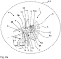
- the electromechanical actuator 2 tensions a brake disc 46 ( 2 ) via the brake pads 4, 4a, a pressure piece, not shown, and with an in Figure 2a rotary lever 7 shown.
- a cam disk 10 is arranged in the electromechanical actuator 2 via a shaft 6 , the cam disk 10 being aligned along the axial axis A and being movable in a rotating manner about the shaft 6 .
- the actuator housing 5 has a cylindrical guide area 12 for guiding a plunger 8 along the axial axis A on the inside.
- the plunger 8 is arranged between a first inner wall 13 of the guide area 12, a second inner wall 13a of the guide area 12 arranged on the end face and the cam disk 10, with a lever arm 8b of the plunger 8 only partially is arranged between the first inner wall 13 of the guide region 12 and the cam disk 10 and the lever arm 8b rests radially on a contact surface 14 of a stop 11 of the cam disk 10, ie is supported radially on the stop 11.
- the stop 11 is arranged at an outer end 15 of the cam disk 10 .
- the cam disk 10 and the stop 11 are one component.
- the plunger 8 is limited axially by the second inner wall 13a of the guide region 12 and the stop 11 .
- the plunger 8 also has a guide roller 8a for guiding the plunger 8 along the cam disk 10 .
- the guide area 12 is designed geometrically in the radial direction in such a way that the ram 8 has a limited freedom of movement about a ram axis AS in the zero position.
- the starting position S of the tappet 8 is defined as the zero position, with no braking process, ie the brake disc 46 being clamped by the brake pads 4, 4a, taking place.
- the plunger 8 rests radially on the cam disc 10 .
- a distance L ( Figure 2a ) between a sliding chamfer 44 of the tappet 8 and the first inner wall 13 of the guide region 12 of the actuator housing 5 is so small that the tappet 8 has a freedom of movement about a tappet axis AS of at most 3° in the zero position, which counteracts jamming of the tappet 8.
- the plunger 8 in a second embodiment 3 are held in position by a spring 20.
- 3 shows the position of the plunger 8 and the spring 20 in the starting position S of the rotary lever 7 ( Fig.2a ).
- the spring 20 is fastened axially to a spring seat 21 via a first end stop 20a.
- the spring receptacle 21 designed as a plate spring is supported radially on the first inner wall 13 of the guide area 12 of the actuator housing 5 .
- the spring receptacle 21 has an opening 21a for the axial passage of the lever arm 8a of the plunger 8.
- the spring 20 is pushed axially over the tappet 8 and is supported axially and radially on the lever arm 8b of the tappet 8 with a second end stop 20b.
- the plunger 8 is prevented from falling out axially, since the spring 20 during an axial movement of the plunger 8 in the direction of the rotary lever 7 ( Figure 2a ) exerts an axial counterforce in the direction of the cam disk 10 and prevents the tappet 8 from rotating about the tappet axis AS.
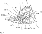
- Another possibility for positioning the plunger 8 of the electromechanical actuator 2 of the disc brake 1 1 shows 4 .
- the plunger 8 is held against falling out of the cam disk 10 via a first spring 30 arranged parallel with respect to the plunger 8 and a second spring 31 arranged in parallel opposite the first spring 30 .
- the second spring 31 has the same components as the first spring 30 .
- the components required for the arrangement of the second spring 31 are identical to the components of the first spring 30, which is why an example is shown in 4 only the side of the electromechanical actuator 2 with the first spring 30 is shown.
- the first spring 30 is on the ram side via a first end stop 30a of the spring 30 and via a first receiving bearing 32 on the shaft 6 ( 2 ) of the plunger 8 is arranged.
- the second spring 31 is arranged on the ram side via a second end stop 31a of the spring 31 and via a second receiving bearing 33 on the shaft 6 of the ram 8.
- the spring 31 is designed to fix the ram 8 axially and radially in a starting position of the rotary lever 7.
- the first receiving bearing 32 and the second receiving bearing 33 are movable and therefore not fixed to the shaft and compensate for a radial and/or axial movement of the plunger 8 triggered by a rotary movement of the cam disk 10 .
- the first spring 30 is held axially on the side opposite the first receiving bearing 32 via a first spring holding element 34 .
- the second spring 31 is in turn held axially on the side opposite the second receiving bearing 33 via a second spring holding element 35 .
- the first spring holding member 34 and the second spring holding member 35 are made of metal material. After the installation of the first spring 30 on the first receiving bearing 32, the first spring retaining element 34 is first positioned radially on the guide area 12 of the actuator housing 5 via a first tongue-groove connection 38 and then via a first screw connection 36 on the first spring Groove connection 38 opposite side of the first spring retaining element 34 fixed axially to the actuator housing 5 by a force and form fit. The assembly described for the first spring 30 also applies to the second spring 32.
- the second spring retaining element 35 is first radially attached to the guide area 12 of the Positioned actuator housing 5 and then fixed via a second screw connection 37 on the opposite side of the second spring-groove connection 39 of the second spring retaining element 35 axially on the actuator housing 5 by a force and form fit.
Landscapes
- Engineering & Computer Science (AREA)
- General Engineering & Computer Science (AREA)
- Mechanical Engineering (AREA)
- Braking Arrangements (AREA)
Description
- Die Erfindung betrifft eine Scheibenbremse mit einem elektromechanischen Aktuator für Fahrzeuge, insbesondere für Nutzfahrzeuge, umfassend eine Bremsscheibe, einen Bremsträger und einen Bremssattel eines Fahrzeuges zum Zuspannen der Bremsscheibe mittels Bremsbelägen. Der elektromechanische Aktuator umfasst einen Motor, eine als Kraftübertragungseinrichtung ausgebildete Kurvenscheibe, und einen als Stelleinheit ausgebildeten Stößel. Elektromechanische Aktuatoren zum Zuspannen von Bremsbelägen für Scheibenbremsen sind hinlänglich bekannt. Die Stelleinheit wird elektrisch mit einem Motor, der mit der Stelleinheit über die Kraftübertragungseinrichtung gekoppelt ist, angetrieben. Die Kraftübertragungseinrichtung kann eine Kurvenscheibe sein, die eine rotierende Bewegung des Motors in eine translatorische Bewegung umwandelt. Die translatorische Bewegung, auch bekannt als Linearbewegung, wird mittels einem mit der Kurvenscheibe wirkverbundenden Stößel auf einen Drehhebel der Scheibenbremse übertragen. Der Drehhebel spannt über ein Druckstück und den Bremsbelägen die Bremsscheibe während eines Bremsvorgangs zu. In aktuellen Lösungen ist der Stößel nach der Montage nicht richtig in einem Gehäuse des elektromechanischen Aktuators fixiert, weshalb der Stößel nach der Positionierung aus dem Drehhebel fallen kann, was zur Folge hat, dass die Kraftübertragung zum Zuspannen der Bremsscheibe unterbrochen ist und die Bremsscheibe nicht zugespannt werden kann.
- Die
DE 10 2017 004436 A1 offenbart eine Scheibenbremse mit einem elektromechanischen Aktuator für Fahrzeuge zum Zuspannen einer Bremsscheibe. Der elektromechanische Aktuator weist eine Kurvenscheibe und einen entlang einer axialen Achse mit der Kurvenscheibe wirkverbundenen Stößel auf. Eine Sicherung gegen eine Fehlstellung des Stößel nach seiner Montage und einer damit verbundenen möglichen Beschädigung von Stößel, Gehäuse und Kurvenscheibe ist nicht vorgesehen. - Die Dokumente
EP 2 239 480 A1 undDE 10 2012 006090 A1 offenbaren eine Scheibenbremse für Nutzfahrzeuge, wobei die Bremsscheibe über eine Zuspanneinheit mit einem Drehhebel und einem mit dem Drehhebel wirkverbundenen Bremszylinder pneumatisch zugespannt wird. -
JP 3 774003 B2 - Aufgabe der Erfindung ist es, die Probleme aus dem Stand der Technik zu überwinden und eine Scheibenbremse mit einem elektromechanischen Aktuator bereitzustellen, der eine Beschädigung des Stößels, der Kurvenscheibe und des Gehäuses des elektromechanischen Aktuators reduziert oder sogar verhindert.
- Gelöst wird die Aufgabe dadurch, dass eine Kurvenscheibe eines elektromechanischen Aktuators einer Scheibenbremse einen Anschlag aufweist und der Anschlag dazu eingerichtet ist den Stößel in einer Ausgangsposition des Drehhebels, in Richtung einer axialen Achse des elektromechanischen Aktuators, entgegengesetzt der Kurvenscheibe, zu fixieren. Als Ausgangsposition des Drehhebels ist die Position gemeint, bei der keine Bremsung seitens des Fahrers initiiert wird. Oder anders ausgedrückt, auf den Drehhebel der Scheibenbremse wird keine Kraft und damit kein Drehmoment aufgebracht. Der Anschlag klemmt den Drehhebel in der Kurvenscheibe ein, wobei der Anschlag zwei Eigenschaften aufweist. Zum einen verhindert der Anschlag eine axiale Bewegung in Richtung des Drehhebels. Zum anderen dient der Anschlag als Auflage für den Drehhebel, sodass der Drehhebel und eine Führung des elektromechanischen Aktuators axial in einer Ebene angeordnet sind und der Anschlag zusammen mit einem weiteren Anschlag am Aktuatorgehäuse eine Drehbewegung um die eigene Achse des Drehhebels verhindert.
- In einer weiteren Ausgestaltung weist der elektromechanische Aktuator zwischen einem Führungsbereich des Stößels, zum Führen des Stößels entlang der axialen Achse, und einer ersten Innenwand des Führungsbereichs des Aktuatorgehäuses einen Abstand auf und der Abstand ist dazu ausgelegt, das der Stößel in einem Bereich, ausgehend von der Ausgangsposition des Drehhebels, zwischen 0° und 5°, besonders vorteilhaft zwischen 0° und 3 °, um ein Stößelachse bewegbar ist. Der Stößel ist einerseits in der Kurvenscheibe angeordnet. Andererseits weist der Stößel bis zu der ersten Innenwand des Führungsbereichs des Aktuatorgehäuses einen Abstand zwischen 0° bis 5° auf. Der Vorteil ist, dass der Stößel in Einbaulage bleibt, also nicht aus der Kurvenscheibe herausfallen kann. Gleichzeitig verhindert der Abstand ein Verklemmen des Stößels in der Führung, ausgelöst durch Toleranzen in der Breite der Führung, die im Herstellungsprozess auftreten.
- In einer weiteren Ausführung weist der Anschlag radial in Richtung des Stößels eine Anlagefläche auf. Der Stößel liegt in der Ausgangsposition des Drehhebels an der Anlagefläche an. Die Anlagefläche erleichtert die Montage des Stößels, insbesondere die Anordnung des Stößels in eine Aufnahme des Drehhebels. Genauer gesagt, kann der Stößel nicht radial wegkippen, sondern bleibt axial in Position, sodass der Drehhebel während der Montage leicht in die Aufnahme des Stößels angeordnet werden kann.
- Zudem weist der Führungsbereich des Aktuatorgehäuses stirnseitig, bezogen auf die axiale Achse, eine zweite Innenwand auf. Der Stößel liegt in der Ausgangsposition des Stößels an der zweiten Innenwand des Führungsbereichs des Aktuatorgehäuses an. Der Stößel ist in der Ausgangsposition also axial zwischen dem Anschlag und der zweiten Innenwand des Führungsbereichs eingeklemmt.
- Eine Fehlstellung des Stößels nach der Montage, also wenn der Stößel nicht in der Aufnahme des Drehhebels angeordnet ist, wird mit der Positionierung des Stößels auf der Anlagefläche und der Positionierung des Stößels an der zweiten Innenwand der Führungsfläche verhindert. Der Stößel verklemmt nicht zwischen dem Drehhebel und der Kurvenscheibe und die Kurvenscheibe, sowie das Gehäuse des elektromechanischen Aktuators werden durch den Stößel nicht beschädigt.
- In einer Weiterbildung weist der Stößel eine Führungsrolle und einen axial in Richtung des Drehhebels der Scheibenbremse angeordneten Hebelarm auf, wobei der Hebelarm in der Ausgangsposition des Drehhebels an der Anlagefläche anliegt. Die Führungsrolle führt den Drehhebel entlang der Kurvenscheibe und der Hebelarm dient als Bindeglied zwischen der Führungsrolle des Stößels und dem Drehhebel der Scheibenbremse.
- Es hat sich darüber hinaus in einer weiteren Ausführung als Vorteil erwiesen, dass die Kurvenscheibe schneckenförmig ausgebildet ist und dass der Anschlag radial an einem äußeren Ende der Kurvenscheibe angeordnet ist. Die Kurvenscheibe ist über eine Welle mit einem Antrieb des elektromechanischen Aktuators in dem Gehäuse des elektromechanischen Aktuators angeordnet. Zwischen dem Anschlag und der Welle weist die Kurvenscheibe eine Vertiefung zur Aufnahme der Führungsrolle des Stößels auf. Oder anders ausgedrückt, der Anschlag ist ein radial verlaufender Ansatz an der Außenseite der Kurvenscheibe, und der radiale Ansatz und die dem radialen Ansatz gegenüberliegende Seite der Kurvenscheibe bilden einen Trog zur Aufnahme des Stößels.
- In einer alternativen zweiten Ausführungsform umschließt eine Feder den Stößel. Die Feder ist axial mit einem ersten Endanschlag an dem Aktuatorgehäuse angeordnet. Zudem ist die Feder axial mit einem zweiten Endanschlag an dem Stößel angeordnet. Die Feder ist wiederum dazu ausgebildet, den Stößel in einer Ausgangsposition des Drehhebels axial und radial zu fixieren. Die alternative Ausführungsform macht sich die Erkenntnis zu Nutze, dass die Feder als Führung des Stößels dient und ein Herausfallen aus der Kurvenscheibe verhindert, und gleichzeitig so variabel ist, dass die Feder eine axiale Bewegung des Stößels zur Betätigung des Drehhebels der Scheibenbremse zulässt.
- Zur richtigen Positionierung der Feder in dem Aktuatorgehäuse weist eine Weiterbildung der zweiten Ausführungsform eine Federaufnahme zum Abstützen des ersten Endanschlags der Feder in axialer Richtung auf. Die Federaufnahme ist in der Führung des Gehäuses und vor dem Drehhebel der Scheibenbremse angeordnet. Die Feder ist eine Druckfeder, wobei die Druckfeder sich an der Federaufnahme axial und radial abstützt.
- In einer weiteren Ausführung der zweiten Ausführungsform ist die Federaufnahme ein Federteller. Der Federteller weist mittig eine Öffnung zum Durchführen des Hebelarms des Stößels auf.
- Das Aktuatorgehäuse, an dem die Federaufnahme befestigt ist, ist in einer vorteilhaften Weiterbildung der zweiten Ausführung ein Aluminiumgehäuse. Unter anderen ist ein Aluminiumgehäuse gegenüber einem Gussstahl leicht und gut verformbar. Mit einem Aluminiumgehäuse ist es möglich, dass die Führung mittels eines Bearbeitungswerkzeugs leicht dem Durchmesser der Federaufnahme angepasst werden kann. Auch eine Nachbearbeitung der Führung, beispielsweise mittels eines Fräßwerkzeugs, zur Anordnung der Federaufnahme ist möglich.
- In einer dritten Ausführung weist der elektromechanische Aktuator der Scheibenbremse, tangential entlang des Stößels, eine erste Feder und gegenüberliegend der ersten Feder, tangential entlang des Stößels, eine zweite Feder auf, wobei die erste Feder und die zweite Feder dazu ausgebildet sind den Stößel axial und radial in einer Ausgangsposition des Drehhebels zu halten. Anders ausgedrückt sind an je einer axialen Seite des Stößels eine Feder angeordnet, die den Stößel in Position halten. Die erste Feder und die zweite Feder können aus einem Metallwerkstoff oder aus einem Kunststoff hergestellt werden.
- In einer Weiterbildung der dritten Ausführungsform weist eine Führungsrolle des Stößels, bezogen auf die axiale Achse, senkrecht und horizontal ein erstes Aufnahmelager zur Fixierung eines Endanschlags der ersten Feder auf. Weiterhin weist die Führungsrolle, bezogen auf die axiale Achse, senkrecht und horizontal in zweites Aufnahmelager zur Fixierung eines Endanschlags der zweiten Feder auf. Das zweite Aufnahmelager ist achsparallel zu dem ersten Aufnahmelager angeordnet. Zwischen dem ersten Aufnahmelager und dem zweiten Aufnahmelager ist der Stößel angeordnet. Der Stößel mit der Führungsrolle ist unabhängig von dem ersten Aufnahmelager und dem zweiten Aufnahmelager beweglich. Das erste Aufnahmelager und das zweite Aufnahmelager sind axiale radial nicht beweglich.
- In einer weiteren Ausführung der dritten Weiterbildung weist der elektromechanische Aktuator ein erstes Federhalteelement zur Aufnahme des Endanschlags der ersten Feder auf. Zusätzlich weist der elektromechanische Aktuator ein zweites Federhalteelement zur Aufnahme des Endanschlags der zweiten Feder auf. Sowohl das erste Federhalteelement als auch das zweite Federhalteelement dienen dazu, dass die erste Feder und die zweite Feder axial gespannt sind und den Stößel gegen ein Herausfallen aus der Kurvenscheibe in Position halten.
- In einer vorteilhaften Ausgestaltung der dritten Ausführungsform ist das erste Federhalteelement radial an einer ersten Innenwand des Führungsbereichs des Aktuatorgehäuses fixiert und das zweite Federhalteelement ist radial an der ersten Innenwand des Führungsbereichs des Aktuatorgehäuses fixiert. Das erste Federhalteelement wird zur Positionierung radial in eine Nut der Führung des elektromechanischen Aktuators gesteckt und das zweite Federhalteelement wird auch zur Positionierung radial in eine Nut der Führung des elektromechanischen Aktuators gesteckt.
- Zudem hat sich in einer weiteren Ausführung der dritten Ausführungsform als Vorteil erwiesen, dass das erste Federhalteelement über eine erste Schraubverbindung und eine erste Feder-Nut-Verbindung an der ersten Innenwand des Führungsbereichs des Aktuatorgehäuses fixiert ist und das das zweite Federhalteelement über eine zweite Schraubverbindung und eine Feder-Nut-Verbindung an der ersten Innenwand des Führungsbereichs des Aktuatorgehäuses fixiert ist.
- Nach der Positionierung des ersten Federhalteelements und des zweiten Federhalteelements wird anschließend das erste Federhalteelement kraftschlüssig über die erste Schraubverbindung axial an dem Gehäuse des elektromechanischen Aktuators befestigt und das zweite Federhaltelement wird kraftschlüssig über die zweite Schraubverbindung axial an dem Gehäuse des elektromechanischen Aktuators befestigt. Sowohl die erste Schraubverbindung verhindert ein Verdrehen des ersten Federhalteelements um die axiale Achse, als auch die zweite Schraubverbindung verhindert ein Verdrehen des zweiten Federhalteelements um die axiale Achse.
- Das Aktuatorgehäuse ist in einer letzten Weiterbildung ein Aluminiumgehäuse. Aluminiumgehäuse sind leicht und mittels eines Bearbeitungswerkzeugs gut verformbar.
- Nachfolgend werden ausgewählte Ausführungsbeispiele der Erfindung anhand der beigefügten Figuren erläutert.
- Es zeigt:
-
Fig. 1 eine Scheibenbremse mit einem elektromechanischen Aktuator in einer Draufsicht, -
Fig. 2 zeigt eine Scheibenbremse mit einem elektromechanischen Aktuator nachFig. 1 in einer seitlich geschnittenen Ansicht, -
Fig. 2a zeigen einen Ausschnitt des elektromechanischen Aktuators nachFig. 2 mit einem Drehhebel der Scheibenbremse nachFig. 1 , -
Fig. 3 zeigt in einer Detailansicht eine zweite Ausführungsform des elektromechanischen Aktuators der Scheibenbremse nachFig. 1 bis 2a , -
Fig. 4 zeigt in einer Detailansicht eine dritte Ausführungsform des elektromechanischen Aktuators der Scheibenbremse nachFig. 1 bis 2a . -
Fig. 1 zeigt eine Scheibenbremse 1 mit einem elektromechanischen Aktuator 2, wobei der elektromechanische Aktuator 2 ein Aktuatorgehäuse 5 aufweist. Der elektromechanische Aktuator 2 ist entlang einer axialen Achse A an der Scheibenbremse 1 angeflanscht. Die Scheibenbremse 1 weist zwei Bremsbeläge 4, 4a auf die gegen ein radiales Herausfallen mittels eines Niederhaltebügels 3 gehalten werden. Zudem ist die Scheibenbremse 1 unterteilt in einen Bremsträger 40 zur Aufnahme der Bremsbeläge 4, 4a und einen Bremssattel 41, wobei der Bremssattel 41 über zwei Führungsbolzen 42, 42a axial gleitend auf dem Bremsträger 40 gelagert ist. Der elektromechanische Aktuator 2 spannt während eines Bremsvorgangs eine Bremsscheibe 46 (Fig. 2 ) über die Bremsbeläge 4, 4a, einem nicht gezeigten Druckstück und mit einem inFigur 2a gezeigten Drehhebel 7 zu. - Wie der elektromechanische Aktuator 2 nach
Fig. 1 im Detail aufgebaut ist, zeigtFig. 2 . In dem elektromechanischen Aktuator 2 ist über eine Welle 6 eine Kurvenscheibe 10 angeordnet, wobei die Kurvenscheibe 10 entlang der axialen Achse A ausgerichtet ist und um die Welle 6 rotierend bewegbar ist. Das Aktuatorgehäuse 5 weist im Inneren einen zylinderförmigen Führungsbereich 12 zum Führen eines Stößels 8 entlang der axialen Achse A auf. Der Stößel 8 ist zwischen einer ersten Innenwand 13 des Führungsbereichs 12, einer zweiten stirnseitig angeordneten Innenwand 13a des Führungsbereichs 12 und der Kurvenscheibe 10 angeordnet, wobei ein Hebelarm 8b des Stößels 8 nur teilweise zwischen der ersten Innenwand 13 des Führungsbereichs 12 und der Kurvenscheibe 10 angeordnet ist und der Hebelarm 8b radial an einer Anlagefläche 14 eines Anschlags 11 der Kurvenscheibe 10 aufliegt, also sich radial an dem Anschlag 11 abstützt. Der Anschlag 11 ist an einem äußeren Ende 15 der Kurvenscheibe 10 angeordnet. Die Kurvenscheibe 10 und der Anschlag 11 sind ein Bauteil. Axial begrenzt wird der Stößel 8 durch die zweite Innenwand 13a des Führungsbereichs 12 und dem Anschlag 11. Der Stößel 8 weist zusätzlich eine Führungsrolle 8a zum Führen des Stößels 8 entlang der Kurvenscheibe 10 auf. Der Führungsbereich 12 ist geometrisch in radialer Richtung so ausgestaltet dass der Stößel 8 in der Nulllage einen begrenzten Bewegungsspielraum um eine Stößelachse AS aufweist. Als Nulllage ist die Ausgangsposition S des Stößels 8 definiert, wobei kein Bremsvorgang, also ein Zuspannen der Bremsscheibe 46 über die Bremsbeläge 4, 4a, erfolgt. Zur Verwirklichung des begrenzten Bewegungsspielraums des Stößels 8 liegt der Stößel 8 zum einen radial an der Kurvenscheibe 10 auf. Zum anderen ist ein Abstand L (Fig. 2a ) zwischen einer Gleitfase 44 des Stößels 8 und der ersten Innenwand 13 des Führungsbereichs 12 des Aktuatorgehäuses 5 so gering, dass der Stößel 8 in der Nullage einen Bewegungsspielraum um eine Stößelachse AS von maximal 3° aufweist, wodurch ein Verklemmen des Stößels 8 entgegengewirkt wird. - Der Abstand L zwischen dem Führungsbereich 12 und dem Stößels 8 des elektromechanischen Aktuators 2 nach
Fig. 1 und2 ist inFig. 2a noch einmal im Detail gezeigt. Weiterhin ist inFigur 2a der Drehhebel 7 der Scheibenbremse 1 nachFigur 1 gezeigt. Der Drehhebel 7 befindet sich in einer Ausgangsposition S. Besonders deutlich wird die Positionierung des Stößels 8 in der Ausgangsposition S des Drehhebels 7. Der Stößel 8 stützt sich axial mit dem Hebelarm 8a in einer Aufnahme 45 des Drehhebels 7 ab. Gegen eine ungewollte Drehbewegung D des Drehhebels 7 und den damit verbundenen Herausfallen des Stößels 8, sichert, wie inFigur 2 beschrieben, der Anschlag 11 der Kurvenscheibe 10 den Stößel 8. - Alternativ kann der Stößel 8 in einer zweiten Ausführungsform nach
Fig. 3 über eine Feder 20 in Position gehalten werden.Fig. 3 zeigt die Stellung des Stößels 8 und der Feder 20 in der Ausgangsposition S des Drehhebels 7 (Fig.2a ). Die Feder 20 ist axial über einen ersten Endanschlag 20a an einer Federaufnahme 21 befestigt. Die als Tellerfeder ausgebildete Federaufnahme 21 stützt sich radial an der ersten Innenwand 13 des Führungsbereichs 12 des Aktuatorgehäuses 5 ab. Zusätzlich weist die Federaufnahme 21 eine Öffnung 21a zum axialen Durchführen des Hebelarms 8a des Stößels 8 auf. Die Feder 20 ist axial über den Stößel 8 geschoben und stützt sich mit einem zweiten Endanschlag 20b axial und radial an dem Hebelarm 8b des Stößels 8 ab. Ein axiales Herausfallen des Stößels 8 wird verhindert, da die Feder 20 während einer axialen Bewegung des Stößels 8 in Richtung des Drehhebels 7 (Fig. 2a ) eine axiale Gegenkraft in Richtung der Kurvenscheibe 10 ausübt und ein Verdrehen des Stößels 8, um die Stößelachse AS verhindert. - Eine weitere Möglichkeit zur Positionierung des Stößels 8 des elektromechanischen Aktuators 2 der Scheibenbremse 1 nach
Fig. 1 zeigtFig. 4 . InFig. 4 wird der Stößel 8 gegen ein Herausfallen aus der Kurvenscheibe 10 über eine parallel in Bezug des Stößels 8 angeordnete erste Feder 30 und eine der ersten Feder 30 gegenüberliegende parallel angeordnete zweite Feder 31 gehalten. Die zweite Feder 31 ist mit der ersten Feder 30 bauteilgleich. Auch die für die Anordnung der zweiten Feder 31 erforderlichen Bauteile sind mit den Bauteilen der ersten Feder 30 bauteilgleich, weshalb exemplarisch inFig. 4 nur die Seite des elektromechanischen Aktuators 2 mit der ersten Feder 30 gezeigt ist. Die erste Feder 30 ist stößelseitig über einen ersten Endanschlag 30a der Feder 30 und über ein erstes Aufnahmelager 32 an der Welle 6 (Fig. 2 ) des Stößels 8 angeordnet. Die zweite Feder 31 ist stößelseitig über einen zweiten Endanschlag 31a der Feder 31 und über ein zweites Aufnahmelager 33 an der Welle 6 des Stößels 8 angeordnet Die Feder 31 ist dazu ausgebildet, den Stößel 8 in einer Ausgangsposition des Drehhebels 7 axial und radial zu fixieren. Das erste Aufnahmelager 32 und das zweite Aufnahmelager 33 sind beweglich, daher nicht fest an der Welle angeordnet und gleichen eine radiale und/oder axiale Bewegung des Stößels 8, ausgelöst durch eine Drehbewegung der Kurvenscheibe 10, aus. Gleichzeitig wird die erste Feder 30 axial an der dem ersten Aufnahmelager 32 gegenüberliegenden Seite über ein erstes Federhalteelement 34 gehalten. Die zweite Feder 31 wird wiederum axial an der dem zweiten Aufnahmelager 33 gegenüberliegenden Seite über ein zweites Federhalteelement 35 gehalten. Das erste Federhalteelement 34 und das zweite Federhalteelement 35 sind aus einem Metallwerkstoff hergestellt. Nach der Montage der ersten Feder 30 an dem ersten Aufnahmelager 32, wird das erste Federhalteelement 34 zunächst über eine erste Feder-Nut-Verbindung 38 radial an dem Führungsbereich 12 des Aktuatorgehäuses 5 positioniert und anschließend über eine erste Schraubverbindung 36 auf der der ersten Feder-Nut-Verbindung 38 gegenüberliegenden Seite des ersten Federhalteelements 34 axial an dem Aktuatorgehäuse 5 durch einen Kraft- und Formschluss fixiert. Die für die erste Feder 30 beschriebene Montage gilt auch für die zweite Feder 32. Nach der Montage der zweiten Feder 31 an dem zweiten Aufnahmelager 33, wird das zweite Federhalteelement 35 zunächst über eine zweite Feder-Nut-Verbindung 39 radial an dem Führungsbereich 12 des Aktuatorgehäuses 5 positioniert und anschließend über eine zweite Schraubverbindung 37 auf der der zweiten Feder-Nut-Verbindung 39 gegenüberliegenden Seite des zweiten Federhalteelements 35 axial an dem Aktuatorgehäuse 5 durch einen Kraft- und Formschluss fixiert. -
- 1
- Scheibenbremse
- 2
- elektromechanischer Aktuator
- 3
- Niederhaltebügel
- 4, 4a
- Bremsbeläge
- 5
- Aktuatorgehäuse
- 6
- Welle
- 7
- Drehhebel
- 8
- Stößel
- 8a
- Führungsrolle
- 8b
- Hebelarm
- 10
- Kurvenscheibe
- 11
- Anschlag
- 12
- Führungsbereich
- 13
- erste Innenwand des Führungsbereichs 12 des Aktuatorgehäuses 5
- 13a
- zweite Innenwand des Führungsbereichs 12 des Aktuatorgehäuses 5
- 14
- Anlagefläche
- 15
- äußeres Ende der Kurvenscheibe 10
- 20
- Feder; Druckfeder
- 20a
- erster Endanschlag der Feder 20
- 20b
- zweiter Endanschlag der Feder 20
- 21
- Federaufnahme
- 21a
- Öffnung der Federaufnahme 21
- 30
- erste Feder
- 31
- zweite Feder
- 30a
- Endanschlag der ersten Feder 30
- 31a
- Endanschlag der zweiten Feder 31
- 32
- erstes Aufnahmelager
- 33
- zweites Aufnahmelager
- 34
- erste Federhalteelement
- 35
- zweite Federhalteelement
- 36
- erste Schraubverbindung
- 37
- zweite Schraubverbindung
- 38
- erste Feder-Nut-Verbindung
- 39
- zweite Feder-Nut-Verbindung
- 40
- Bremsträger
- 41
- Bremssattel
- 42, 42a
- Führungsbolzen
- 44
- Gleitfase des Stößels 8
- 45
- Aufnahme des Drehhebels 7
- 46
- Bremsscheibe
- A
- axiale Achse des elektromechanischen Aktuators
- A-A
- Schnitt
- L
- Abstand
- AS
- Stößelachse
- D
- Drehbewegung des Drehhebels 7
- S
- Ausgangsposition
Claims (15)
- Scheibenbremse (1) mit einem elektromechanischen Aktuator (2) für Fahrzeuge, insbesondere für Nutzfahrzeuge zum Zuspannen einer Bremsscheibe (46) über einen Drehhebel (7) und zwei Bremsbelägen (4, 4a), und wobei der elektromechanische Aktuator (2) ein Aktuatorgehäuse (5), eine in dem Aktuatorgehäuse (5) über eine Welle (6) angeordnete Kurvenscheibe (10) und einen entlang einer axialen Achse (A) mit der Kurvenscheibe (10) wirkverbundenden Stößel (8) umfasst, dadurch gekennzeichnet, dass die Kurvenscheibe (10) einen Anschlag (11) aufweist und der Anschlag (11) dazu eingerichtet ist den Stößel (8) in einer Ausgangsposition (S) des Drehhebels (7) in Richtung einer axialen Achse (A) des elektromechanischen Aktuators (2), entgegengesetzt der Kurvenscheibe (10), zu fixieren.
- Scheibenbremse (1) nach Anspruch 1, dadurch gekennzeichnet, dass der elektromechanische Aktuator (2) zwischen einer Gleitfase (44) des Stößels (8), einem Führungsbereich (12) des Stößels (8), zum Führen des Stößels (8) entlang der axialen Achse (A), und einer ersten Innenwand (13) eines Führungsbereichs 12 des Aktuatorgehäuses (5) einen Abstand (L) aufweist und der Abstand (L) dazu ausgelegt ist, das der Stößel (8) in einem Bereich, ausgehend von der Ausgangsposition (S) des Drehhebels (7), zwischen 0° und 5° um ein Stößelachse (AS) bewegbar ist.
- Scheibenbremse (1) nach Anspruch 1 oder 2, dadurch gekennzeichnet, dass der Anschlag (11), radial in Richtung des Stößels (8) eine Anlagefläche (14) aufweist und der Stößel (8) in der Ausgangsposition (S) an der Anlagefläche (14) aufliegt und wobei der Führungsbereich (12) des Aktuatorgehäuses (5) stirnseitig, bezogen auf die axiale Achse (A), eine zweite Innenwand 13a aufweist und der Stößel (8) in der Ausgangsposition (S) an der zweiten Innenwand 13a des Führungsbereichs (12) des Aktuatorgehäuses (5) anliegt.
- Scheibenbremse (1) nach Anspruch 3, dadurch gekennzeichnet, dass der Stößel (8) eine Führungsrolle (8a) und einen axial in Richtung des Drehhebels (7) der Scheibenbremse (1) angeordneten Hebelarm (8b) aufweist und der Hebelarm (8b) in der Ausgangsposition (S) radial an der Anlagefläche (14) anliegt.
- Scheibenbremse (1) nach einem der vorangegangenen Ansprüche, dadurch gekennzeichnet, dass die Kurvenscheibe (10) schneckenförmig ausgebildet ist und dass der Anschlag (11) radial an einem äußeren Ende (15) der Kurvenscheibe (10) angeordnet ist.
- Scheibenbremse (1) mit einem elektromechanischen Aktuator (2) für Fahrzeuge, insbesondere für Nutzfahrzeuge zum Zuspannen einer Bremsscheibe (46) über einen Drehhebel (7) und zwei Bremsbelägen (4, 4a), und wobei der elektromechanische Aktuator (2) ein Aktuatorgehäuse (5), eine in dem Aktuatorgehäuse (5), über eine Welle (6), angeordnete Kurvenscheibe (10) und einen entlang einer axialen Achse (A) mit der Kurvenscheibe (10) wirkverbundenden Stößel (8) umfasst, dadurch gekennzeichnet, dass eine Feder (20) den Stößel (8) umschließt, die Feder (20) axial mit einem ersten Endanschlag (20a) an dem Aktuatorgehäuse (5) angeordnet ist, die Feder (20) axial mit einem zweiten Endanschlag (20b) an dem Stößel (8) angeordnet ist und die Feder (20) dazu ausgebildet ist, den Stößel (8) in einer Ausgangsposition (S) des Drehhebels (7) axial und radial zu fixieren.
- Scheibenbremse (1) nach Anspruch 6, dadurch gekennzeichnet, dass das Aktuatorgehäuse (5) eine Federaufnahme (21) aufweist und die Federaufnahme (21) zum Abstützen des ersten Endanschlags (20a) der Feder (20) in axialer Richtung ausgebildet ist.
- Scheibenbremse (1) nach Anspruch 7, dadurch gekennzeichnet dass die Federaufnahme (21) ein Federteller (21) ist und der Federteller (21) eine Öffnung (21a) zum Durchführen des Stößels (8) aufweist.
- Scheibenbremse (1) nach einem der Ansprüche 6 bis 8, dadurch gekennzeichnet, dass die Feder (20) eine Druckfeder (20) ist.
- Scheibenbremse (1) mit einem elektromechanischen Aktuator (2) für Fahrzeuge, insbesondere für Nutzfahrzeuge zum Zuspannen einer Bremsscheibe (46) über einen Drehhebel (7) und zwei Bremsbelägen (4, 4a), und wobei der elektromechanische Aktuator (2) ein Aktuatorgehäuse (5), eine in dem Aktuatorgehäuse (5), über eine Welle (6), angeordnete Kurvenscheibe (10) und einen entlang einer axialen Achse (A) mit der Kurvenscheibe (10) wirkverbundenden Stößels (8) umfasst, dadurch gekennzeichnet, dass tangential entlang des Stößel (8) eine erste Feder (30) und eine der ersten Feder (30) gegenüberliegende parallel angeordnete zweite Feder (31) angeordnet sind, wobei je einer axialen Seite des Stößels (8) eine der ersten Feder (30) und der zweiten Feder (31) angeordnet ist und wobei die erste Feder (30) und die zweite Feder (31) dazu ausgebildet sind den Stößel (8) axial und radial in einer Ausgangsposition (S) des Drehhebels (7) zu halten.
- Scheibenbremse (1) nach Anspruch 10, dadurch gekennzeichnet, dass eine Führungsrolle (8a) des Stößels (8), bezogen auf die axiale Achse (A), senkrecht und horizontal ein erstes Aufnahmelager (32) zur Fixierung eines Endanschlags (30a) der ersten Feder (30) aufweist und das die Führungsrolle (8a), bezogen auf die axiale Achse (A), senkrecht und horizontal ein zweites Aufnahmelager (33) zur Fixierung eines Endanschlags (31a) der zweiten Feder (31) aufweist.
- Scheibenbremse (1) nach Anspruch 10 oder 11, dadurch gekennzeichnet, dass der elektromechanische Aktuator (2) ein erstes Federhaltelement (34) zur Aufnahme des Endanschlags (30a) der ersten Feder (30) aufweist und das der elektromechanische Aktuator (2) ein zweites Federhalteelement (35) zur Aufnahme des Endanschlags (31a) der zweiten Feder (31) aufweist.
- Scheibenbremse (1) nach einem der Ansprüche 10 bis 12, dadurch gekennzeichnet, dass das erste Federhalteelement (34) radial an einer ersten Innenwand (13) des Führungsbereichs 12 des Aktuatorgehäuses (5) fixiert ist und dass das zweite Federhalteelement (35) radial an der ersten Innenwand (13) des Führungsbereichs 12 des Aktuatorgehäuses (5) fixiert sind.
- Scheibenbremse nach Anspruch 13, dadurch gekennzeichnet, dass das erste Federhalteelement (34) über eine erste Schraubverbindung (36) und einer erste Feder-Nut-Verbindung (38) an der ersten Innenwand (13) des Führungsbereichs 12 des Aktuatorgehäuses (5) fixiert ist und dass das zweite Federhalteelement (35) über eine zweite Schraubverbindung (37) und einer Feder-Nut-Verbindung (39) an der ersten Innenwand (13) des Führungsbereichs 12 des Aktuatorgehäuses (5) fixiert ist.
- Scheibenbremse (1) nach einem der vorangegangenen Ansprüchen, dadurch gekennzeichnet, dass das Aktuatorgehäuse (5) ein Aluminiumgehäuse (5) ist.
Priority Applications (3)
| Application Number | Priority Date | Filing Date | Title |
|---|---|---|---|
| EP19193161.7A EP3783242B1 (de) | 2019-08-22 | 2019-08-22 | Scheibenbremse für fahrzeuge, insbesondere für nutzahrzeuge, mit einem elektromechanischen aktuator |
| US16/998,011 US12104665B2 (en) | 2019-08-22 | 2020-08-20 | Disc brake having an electromechanical actuator |
| CN202010849471.5A CN112413014B (zh) | 2019-08-22 | 2020-08-21 | 车辆的、尤其是商用车辆的具有机电促动器的盘式制动器 |
Applications Claiming Priority (1)
| Application Number | Priority Date | Filing Date | Title |
|---|---|---|---|
| EP19193161.7A EP3783242B1 (de) | 2019-08-22 | 2019-08-22 | Scheibenbremse für fahrzeuge, insbesondere für nutzahrzeuge, mit einem elektromechanischen aktuator |
Publications (2)
| Publication Number | Publication Date |
|---|---|
| EP3783242A1 EP3783242A1 (de) | 2021-02-24 |
| EP3783242B1 true EP3783242B1 (de) | 2022-12-28 |
Family
ID=67734587
Family Applications (1)
| Application Number | Title | Priority Date | Filing Date |
|---|---|---|---|
| EP19193161.7A Active EP3783242B1 (de) | 2019-08-22 | 2019-08-22 | Scheibenbremse für fahrzeuge, insbesondere für nutzahrzeuge, mit einem elektromechanischen aktuator |
Country Status (2)
| Country | Link |
|---|---|
| EP (1) | EP3783242B1 (de) |
| CN (1) | CN112413014B (de) |
Families Citing this family (1)
| Publication number | Priority date | Publication date | Assignee | Title |
|---|---|---|---|---|
| DE102021115795A1 (de) | 2021-06-18 | 2022-12-22 | Bayerische Motoren Werke Aktiengesellschaft | Bremssattel einer elektromechanisch betreibbaren Reibungsbremse eines Fahrzeuges |
Citations (1)
| Publication number | Priority date | Publication date | Assignee | Title |
|---|---|---|---|---|
| EP2239480B1 (de) * | 2009-04-08 | 2012-07-11 | Knorr-Bremse Systeme für Nutzfahrzeuge GmbH | Scheibenbremse für ein Nutzfahrzeug |
Family Cites Families (10)
| Publication number | Priority date | Publication date | Assignee | Title |
|---|---|---|---|---|
| DE1475501B2 (de) * | 1965-11-27 | 1972-01-27 | Alfred Teves Gmbh, 6000 Frankfurt | Mechanisch zu betaetigende teilbelagscheibenbremse mit selbstverstaerkender bremswirkung |
| US4154321A (en) * | 1977-03-14 | 1979-05-15 | Wagner Electric Corporation | Cam actuated disc brake |
| DE4409867C1 (de) * | 1994-03-22 | 1995-08-17 | Knorr Bremse Systeme | Bremsklotzeinheit für Schienenfahrzeuge |
| JP3774003B2 (ja) * | 1996-11-20 | 2006-05-10 | 株式会社日立製作所 | ディスクブレーキ |
| JPH11247910A (ja) * | 1998-03-04 | 1999-09-14 | Nisshinbo Ind Inc | ディスクブレーキ装置 |
| AT508296A1 (de) * | 2009-05-19 | 2010-12-15 | Ve Vienna Engineering Forschungs Und Entwicklungs Gmbh | Reibungsbremse |
| CN201496445U (zh) * | 2009-07-06 | 2010-06-02 | 厦门亨东制动系统有限公司 | 一种手刹线挂点一体式的后轮制动卡钳 |
| DE102012006090B4 (de) * | 2012-03-26 | 2017-11-16 | Knorr-Bremse Systeme für Nutzfahrzeuge GmbH | Scheibenbremse |
| DE102017004436A1 (de) * | 2017-05-09 | 2018-11-15 | Wabco Europe Bvba | Elektromechanischer Bremsenaktuator |
| CN107237843B (zh) * | 2017-08-03 | 2022-12-27 | 安吉亚太制动系统有限公司 | 轻型商用车用浮动单楔式制动器 |
-
2019
- 2019-08-22 EP EP19193161.7A patent/EP3783242B1/de active Active
-
2020
- 2020-08-21 CN CN202010849471.5A patent/CN112413014B/zh active Active
Patent Citations (1)
| Publication number | Priority date | Publication date | Assignee | Title |
|---|---|---|---|---|
| EP2239480B1 (de) * | 2009-04-08 | 2012-07-11 | Knorr-Bremse Systeme für Nutzfahrzeuge GmbH | Scheibenbremse für ein Nutzfahrzeug |
Also Published As
| Publication number | Publication date |
|---|---|
| US20210054888A1 (en) | 2021-02-25 |
| CN112413014A (zh) | 2021-02-26 |
| EP3783242A1 (de) | 2021-02-24 |
| CN112413014B (zh) | 2022-06-17 |
Similar Documents
| Publication | Publication Date | Title |
|---|---|---|
| DE19923900B4 (de) | Encoder mit zusammensteckbarem Gehäuse | |
| DE112011101764B4 (de) | Reibungskupplung mit weggesteuerter Verschleißkompensation und Verfahren zu deren Montage | |
| DE2638508B2 (de) | Führung für den Sattel einer hydraulisch betätigbaren Schwimmsattelteilbelagscheibenbremse für Fahrzeuge | |
| EP4185784B1 (de) | Verfahren zum herstellen eines getriebes | |
| DE102009014117A1 (de) | Klemmvorrichtung | |
| DE102018100458B4 (de) | Getriebegehäuseeinheit und Getriebeeinheit mit keilförmigem Ausgleichselement zum Axialspielausgleich | |
| EP3783242B1 (de) | Scheibenbremse für fahrzeuge, insbesondere für nutzahrzeuge, mit einem elektromechanischen aktuator | |
| DE102004045218A1 (de) | Bremsenträger | |
| DE60205878T2 (de) | Brems-kupplung anordnung | |
| EP3835612A1 (de) | Scheibenbremse, insbesondere für nutzfahrzeuge und fahrzeug mit einer scheibenbremse, insbesondere nutzfahrzeug mit einer scheibenbremse | |
| DE69409642T2 (de) | Schwimmsattel scheibenbremse | |
| EP4226063B1 (de) | Elektromagnetische federdruckbremse und herstellverfahren | |
| EP2620637A1 (de) | Arretiervorrichtung für einen Triebstrang einer Windenergieanlage sowie Verfahren zum Arretieren des Triebstranges | |
| AT523278B1 (de) | Pyrotechnischer Aktuator | |
| EP3106691B1 (de) | Lagerfassung, verteilungselement und vakuumpume | |
| DE102007027175A1 (de) | Hebelsystem sowie Verfahren zu dessen Montage | |
| WO2009021904A1 (de) | Elektrische maschine mit einer vorrichtung zur befestigung eines stators | |
| EP0563689A2 (de) | Scheibenbremse für ein Kraftfahrzeug | |
| DE102012025353B4 (de) | Vorrichtung zum Runddrücken eines hohlzylindrischen Werkstücks | |
| EP2933522B1 (de) | Sattelscheibenbremse und betätigungseinrichtung einer solchen sattelscheibenbremse | |
| DE102014007568A1 (de) | Befestigungsanordnung eines Statorelements einer elektrischen Maschine an einem Bauelement, insbesondere für einen Kraftwagen | |
| DE102015115856A1 (de) | Scheibenbremse für ein Nutzfahrzeug | |
| EP1884676B1 (de) | Kupplungsvorrichtung, insbesondere Kraftfahrzeug-Kupplungsvorrichtung | |
| EP1897660A2 (de) | Greifelement für einen Federspanner und Federspanner | |
| DE102018123053A1 (de) | Elektrischer Kupplungsaktuator mit Vierpunktlager für Spindelmutter |
Legal Events
| Date | Code | Title | Description |
|---|---|---|---|
| PUAI | Public reference made under article 153(3) epc to a published international application that has entered the european phase |
Free format text: ORIGINAL CODE: 0009012 |
|
| STAA | Information on the status of an ep patent application or granted ep patent |
Free format text: STATUS: THE APPLICATION HAS BEEN PUBLISHED |
|
| AK | Designated contracting states |
Kind code of ref document: A1 Designated state(s): AL AT BE BG CH CY CZ DE DK EE ES FI FR GB GR HR HU IE IS IT LI LT LU LV MC MK MT NL NO PL PT RO RS SE SI SK SM TR |
|
| AX | Request for extension of the european patent |
Extension state: BA ME |
|
| RAP3 | Party data changed (applicant data changed or rights of an application transferred) |
Owner name: ZF CV SYSTEMS GLOBAL GMBH |
|
| STAA | Information on the status of an ep patent application or granted ep patent |
Free format text: STATUS: REQUEST FOR EXAMINATION WAS MADE |
|
| 17P | Request for examination filed |
Effective date: 20210824 |
|
| RBV | Designated contracting states (corrected) |
Designated state(s): AL AT BE BG CH CY CZ DE DK EE ES FI FR GB GR HR HU IE IS IT LI LT LU LV MC MK MT NL NO PL PT RO RS SE SI SK SM TR |
|
| REG | Reference to a national code |
Ref country code: DE Ref legal event code: R079 Ref document number: 502019006616 Country of ref document: DE Free format text: PREVIOUS MAIN CLASS: F16D0065000000 Ipc: F16D0055225500 |
|
| RIC1 | Information provided on ipc code assigned before grant |
Ipc: F16D 125/32 20120101ALN20220801BHEP Ipc: F16D 65/00 20060101ALN20220801BHEP Ipc: F16D 121/24 20120101ALN20220801BHEP Ipc: F16D 55/2255 20060101AFI20220801BHEP |
|
| GRAP | Despatch of communication of intention to grant a patent |
Free format text: ORIGINAL CODE: EPIDOSNIGR1 |
|
| STAA | Information on the status of an ep patent application or granted ep patent |
Free format text: STATUS: GRANT OF PATENT IS INTENDED |
|
| INTG | Intention to grant announced |
Effective date: 20221020 |
|
| GRAS | Grant fee paid |
Free format text: ORIGINAL CODE: EPIDOSNIGR3 |
|
| GRAA | (expected) grant |
Free format text: ORIGINAL CODE: 0009210 |
|
| STAA | Information on the status of an ep patent application or granted ep patent |
Free format text: STATUS: THE PATENT HAS BEEN GRANTED |
|
| AK | Designated contracting states |
Kind code of ref document: B1 Designated state(s): AL AT BE BG CH CY CZ DE DK EE ES FI FR GB GR HR HU IE IS IT LI LT LU LV MC MK MT NL NO PL PT RO RS SE SI SK SM TR |
|
| REG | Reference to a national code |
Ref country code: GB Ref legal event code: FG4D Free format text: NOT ENGLISH |
|
| REG | Reference to a national code |
Ref country code: CH Ref legal event code: EP |
|
| REG | Reference to a national code |
Ref country code: DE Ref legal event code: R096 Ref document number: 502019006616 Country of ref document: DE |
|
| REG | Reference to a national code |
Ref country code: AT Ref legal event code: REF Ref document number: 1540680 Country of ref document: AT Kind code of ref document: T Effective date: 20230115 |
|
| REG | Reference to a national code |
Ref country code: IE Ref legal event code: FG4D Free format text: LANGUAGE OF EP DOCUMENT: GERMAN |
|
| REG | Reference to a national code |
Ref country code: LT Ref legal event code: MG9D |
|
| PG25 | Lapsed in a contracting state [announced via postgrant information from national office to epo] |
Ref country code: SE Free format text: LAPSE BECAUSE OF FAILURE TO SUBMIT A TRANSLATION OF THE DESCRIPTION OR TO PAY THE FEE WITHIN THE PRESCRIBED TIME-LIMIT Effective date: 20221228 Ref country code: NO Free format text: LAPSE BECAUSE OF FAILURE TO SUBMIT A TRANSLATION OF THE DESCRIPTION OR TO PAY THE FEE WITHIN THE PRESCRIBED TIME-LIMIT Effective date: 20230328 Ref country code: LT Free format text: LAPSE BECAUSE OF FAILURE TO SUBMIT A TRANSLATION OF THE DESCRIPTION OR TO PAY THE FEE WITHIN THE PRESCRIBED TIME-LIMIT Effective date: 20221228 Ref country code: FI Free format text: LAPSE BECAUSE OF FAILURE TO SUBMIT A TRANSLATION OF THE DESCRIPTION OR TO PAY THE FEE WITHIN THE PRESCRIBED TIME-LIMIT Effective date: 20221228 |
|
| REG | Reference to a national code |
Ref country code: NL Ref legal event code: MP Effective date: 20221228 |
|
| PG25 | Lapsed in a contracting state [announced via postgrant information from national office to epo] |
Ref country code: RS Free format text: LAPSE BECAUSE OF FAILURE TO SUBMIT A TRANSLATION OF THE DESCRIPTION OR TO PAY THE FEE WITHIN THE PRESCRIBED TIME-LIMIT Effective date: 20221228 Ref country code: LV Free format text: LAPSE BECAUSE OF FAILURE TO SUBMIT A TRANSLATION OF THE DESCRIPTION OR TO PAY THE FEE WITHIN THE PRESCRIBED TIME-LIMIT Effective date: 20221228 Ref country code: HR Free format text: LAPSE BECAUSE OF FAILURE TO SUBMIT A TRANSLATION OF THE DESCRIPTION OR TO PAY THE FEE WITHIN THE PRESCRIBED TIME-LIMIT Effective date: 20221228 Ref country code: GR Free format text: LAPSE BECAUSE OF FAILURE TO SUBMIT A TRANSLATION OF THE DESCRIPTION OR TO PAY THE FEE WITHIN THE PRESCRIBED TIME-LIMIT Effective date: 20230329 |
|
| PG25 | Lapsed in a contracting state [announced via postgrant information from national office to epo] |
Ref country code: NL Free format text: LAPSE BECAUSE OF FAILURE TO SUBMIT A TRANSLATION OF THE DESCRIPTION OR TO PAY THE FEE WITHIN THE PRESCRIBED TIME-LIMIT Effective date: 20221228 |
|
| P01 | Opt-out of the competence of the unified patent court (upc) registered |
Effective date: 20230528 |
|
| PG25 | Lapsed in a contracting state [announced via postgrant information from national office to epo] |
Ref country code: SM Free format text: LAPSE BECAUSE OF FAILURE TO SUBMIT A TRANSLATION OF THE DESCRIPTION OR TO PAY THE FEE WITHIN THE PRESCRIBED TIME-LIMIT Effective date: 20221228 Ref country code: RO Free format text: LAPSE BECAUSE OF FAILURE TO SUBMIT A TRANSLATION OF THE DESCRIPTION OR TO PAY THE FEE WITHIN THE PRESCRIBED TIME-LIMIT Effective date: 20221228 Ref country code: PT Free format text: LAPSE BECAUSE OF FAILURE TO SUBMIT A TRANSLATION OF THE DESCRIPTION OR TO PAY THE FEE WITHIN THE PRESCRIBED TIME-LIMIT Effective date: 20230428 Ref country code: ES Free format text: LAPSE BECAUSE OF FAILURE TO SUBMIT A TRANSLATION OF THE DESCRIPTION OR TO PAY THE FEE WITHIN THE PRESCRIBED TIME-LIMIT Effective date: 20221228 Ref country code: EE Free format text: LAPSE BECAUSE OF FAILURE TO SUBMIT A TRANSLATION OF THE DESCRIPTION OR TO PAY THE FEE WITHIN THE PRESCRIBED TIME-LIMIT Effective date: 20221228 Ref country code: CZ Free format text: LAPSE BECAUSE OF FAILURE TO SUBMIT A TRANSLATION OF THE DESCRIPTION OR TO PAY THE FEE WITHIN THE PRESCRIBED TIME-LIMIT Effective date: 20221228 |
|
| PG25 | Lapsed in a contracting state [announced via postgrant information from national office to epo] |
Ref country code: SK Free format text: LAPSE BECAUSE OF FAILURE TO SUBMIT A TRANSLATION OF THE DESCRIPTION OR TO PAY THE FEE WITHIN THE PRESCRIBED TIME-LIMIT Effective date: 20221228 Ref country code: PL Free format text: LAPSE BECAUSE OF FAILURE TO SUBMIT A TRANSLATION OF THE DESCRIPTION OR TO PAY THE FEE WITHIN THE PRESCRIBED TIME-LIMIT Effective date: 20221228 Ref country code: IS Free format text: LAPSE BECAUSE OF FAILURE TO SUBMIT A TRANSLATION OF THE DESCRIPTION OR TO PAY THE FEE WITHIN THE PRESCRIBED TIME-LIMIT Effective date: 20230428 Ref country code: AL Free format text: LAPSE BECAUSE OF FAILURE TO SUBMIT A TRANSLATION OF THE DESCRIPTION OR TO PAY THE FEE WITHIN THE PRESCRIBED TIME-LIMIT Effective date: 20221228 |
|
| REG | Reference to a national code |
Ref country code: DE Ref legal event code: R097 Ref document number: 502019006616 Country of ref document: DE |
|
| PG25 | Lapsed in a contracting state [announced via postgrant information from national office to epo] |
Ref country code: DK Free format text: LAPSE BECAUSE OF FAILURE TO SUBMIT A TRANSLATION OF THE DESCRIPTION OR TO PAY THE FEE WITHIN THE PRESCRIBED TIME-LIMIT Effective date: 20221228 |
|
| PGFP | Annual fee paid to national office [announced via postgrant information from national office to epo] |
Ref country code: GB Payment date: 20230629 Year of fee payment: 5 |
|
| PLBE | No opposition filed within time limit |
Free format text: ORIGINAL CODE: 0009261 |
|
| STAA | Information on the status of an ep patent application or granted ep patent |
Free format text: STATUS: NO OPPOSITION FILED WITHIN TIME LIMIT |
|
| PGFP | Annual fee paid to national office [announced via postgrant information from national office to epo] |
Ref country code: FR Payment date: 20230703 Year of fee payment: 5 Ref country code: DE Payment date: 20230627 Year of fee payment: 5 |
|
| 26N | No opposition filed |
Effective date: 20230929 |
|
| PG25 | Lapsed in a contracting state [announced via postgrant information from national office to epo] |
Ref country code: SI Free format text: LAPSE BECAUSE OF FAILURE TO SUBMIT A TRANSLATION OF THE DESCRIPTION OR TO PAY THE FEE WITHIN THE PRESCRIBED TIME-LIMIT Effective date: 20221228 |
|
| PG25 | Lapsed in a contracting state [announced via postgrant information from national office to epo] |
Ref country code: MC Free format text: LAPSE BECAUSE OF FAILURE TO SUBMIT A TRANSLATION OF THE DESCRIPTION OR TO PAY THE FEE WITHIN THE PRESCRIBED TIME-LIMIT Effective date: 20221228 |
|
| REG | Reference to a national code |
Ref country code: CH Ref legal event code: PL |
|
| PG25 | Lapsed in a contracting state [announced via postgrant information from national office to epo] |
Ref country code: MC Free format text: LAPSE BECAUSE OF FAILURE TO SUBMIT A TRANSLATION OF THE DESCRIPTION OR TO PAY THE FEE WITHIN THE PRESCRIBED TIME-LIMIT Effective date: 20221228 |
|
| PG25 | Lapsed in a contracting state [announced via postgrant information from national office to epo] |
Ref country code: LU Free format text: LAPSE BECAUSE OF NON-PAYMENT OF DUE FEES Effective date: 20230822 |
|
| PG25 | Lapsed in a contracting state [announced via postgrant information from national office to epo] |
Ref country code: LU Free format text: LAPSE BECAUSE OF NON-PAYMENT OF DUE FEES Effective date: 20230822 Ref country code: CH Free format text: LAPSE BECAUSE OF NON-PAYMENT OF DUE FEES Effective date: 20230831 |
|
| REG | Reference to a national code |
Ref country code: BE Ref legal event code: MM Effective date: 20230831 |
|
| REG | Reference to a national code |
Ref country code: IE Ref legal event code: MM4A |
|
| PG25 | Lapsed in a contracting state [announced via postgrant information from national office to epo] |
Ref country code: IT Free format text: LAPSE BECAUSE OF FAILURE TO SUBMIT A TRANSLATION OF THE DESCRIPTION OR TO PAY THE FEE WITHIN THE PRESCRIBED TIME-LIMIT Effective date: 20221228 |
|
| PG25 | Lapsed in a contracting state [announced via postgrant information from national office to epo] |
Ref country code: IE Free format text: LAPSE BECAUSE OF NON-PAYMENT OF DUE FEES Effective date: 20230822 |
|
| PG25 | Lapsed in a contracting state [announced via postgrant information from national office to epo] |
Ref country code: IE Free format text: LAPSE BECAUSE OF NON-PAYMENT OF DUE FEES Effective date: 20230822 |
|
| PG25 | Lapsed in a contracting state [announced via postgrant information from national office to epo] |
Ref country code: BE Free format text: LAPSE BECAUSE OF NON-PAYMENT OF DUE FEES Effective date: 20230831 |