EP3782565B1 - Wirbelfixierungsvorrichtung - Google Patents
Wirbelfixierungsvorrichtung Download PDFInfo
- Publication number
- EP3782565B1 EP3782565B1 EP20188689.2A EP20188689A EP3782565B1 EP 3782565 B1 EP3782565 B1 EP 3782565B1 EP 20188689 A EP20188689 A EP 20188689A EP 3782565 B1 EP3782565 B1 EP 3782565B1
- Authority
- EP
- European Patent Office
- Prior art keywords
- expanding
- expanding device
- operating lever
- vertebral fixation
- medical filler
- Prior art date
- Legal status (The legal status is an assumption and is not a legal conclusion. Google has not performed a legal analysis and makes no representation as to the accuracy of the status listed.)
- Active
Links
Images


Classifications
-
- A—HUMAN NECESSITIES
- A61—MEDICAL OR VETERINARY SCIENCE; HYGIENE
- A61B—DIAGNOSIS; SURGERY; IDENTIFICATION
- A61B17/00—Surgical instruments, devices or methods
- A61B17/56—Surgical instruments or methods for treatment of bones or joints; Devices specially adapted therefor
- A61B17/58—Surgical instruments or methods for treatment of bones or joints; Devices specially adapted therefor for osteosynthesis, e.g. bone plates, screws or setting implements
- A61B17/88—Osteosynthesis instruments; Methods or means for implanting or extracting internal or external fixation devices
- A61B17/8802—Equipment for handling bone cement or other fluid fillers
- A61B17/8805—Equipment for handling bone cement or other fluid fillers for introducing fluid filler into bone or extracting it
- A61B17/8811—Equipment for handling bone cement or other fluid fillers for introducing fluid filler into bone or extracting it characterised by the introducer tip, i.e. the part inserted into or onto the bone
-
- A—HUMAN NECESSITIES
- A61—MEDICAL OR VETERINARY SCIENCE; HYGIENE
- A61B—DIAGNOSIS; SURGERY; IDENTIFICATION
- A61B17/00—Surgical instruments, devices or methods
- A61B17/56—Surgical instruments or methods for treatment of bones or joints; Devices specially adapted therefor
- A61B17/58—Surgical instruments or methods for treatment of bones or joints; Devices specially adapted therefor for osteosynthesis, e.g. bone plates, screws or setting implements
- A61B17/68—Internal fixation devices, including fasteners and spinal fixators, even if a part thereof projects from the skin
- A61B17/70—Spinal positioners or stabilisers, e.g. stabilisers comprising fluid filler in an implant
- A61B17/7097—Stabilisers comprising fluid filler in an implant, e.g. balloon; devices for inserting or filling such implants
-
- A—HUMAN NECESSITIES
- A61—MEDICAL OR VETERINARY SCIENCE; HYGIENE
- A61B—DIAGNOSIS; SURGERY; IDENTIFICATION
- A61B17/00—Surgical instruments, devices or methods
- A61B17/56—Surgical instruments or methods for treatment of bones or joints; Devices specially adapted therefor
- A61B17/58—Surgical instruments or methods for treatment of bones or joints; Devices specially adapted therefor for osteosynthesis, e.g. bone plates, screws or setting implements
- A61B17/68—Internal fixation devices, including fasteners and spinal fixators, even if a part thereof projects from the skin
- A61B17/70—Spinal positioners or stabilisers, e.g. stabilisers comprising fluid filler in an implant
- A61B17/7094—Solid vertebral fillers; devices for inserting such fillers
-
- A—HUMAN NECESSITIES
- A61—MEDICAL OR VETERINARY SCIENCE; HYGIENE
- A61B—DIAGNOSIS; SURGERY; IDENTIFICATION
- A61B17/00—Surgical instruments, devices or methods
- A61B17/56—Surgical instruments or methods for treatment of bones or joints; Devices specially adapted therefor
- A61B17/58—Surgical instruments or methods for treatment of bones or joints; Devices specially adapted therefor for osteosynthesis, e.g. bone plates, screws or setting implements
- A61B17/68—Internal fixation devices, including fasteners and spinal fixators, even if a part thereof projects from the skin
- A61B17/72—Intramedullary devices, e.g. pins or nails
- A61B17/7233—Intramedullary devices, e.g. pins or nails with special means of locking the nail to the bone
- A61B17/7258—Intramedullary devices, e.g. pins or nails with special means of locking the nail to the bone with laterally expanding parts, e.g. for gripping the bone
- A61B17/7275—Intramedullary devices, e.g. pins or nails with special means of locking the nail to the bone with laterally expanding parts, e.g. for gripping the bone with expanding cylindrical parts
-
- A—HUMAN NECESSITIES
- A61—MEDICAL OR VETERINARY SCIENCE; HYGIENE
- A61B—DIAGNOSIS; SURGERY; IDENTIFICATION
- A61B17/00—Surgical instruments, devices or methods
- A61B17/56—Surgical instruments or methods for treatment of bones or joints; Devices specially adapted therefor
- A61B17/58—Surgical instruments or methods for treatment of bones or joints; Devices specially adapted therefor for osteosynthesis, e.g. bone plates, screws or setting implements
- A61B17/88—Osteosynthesis instruments; Methods or means for implanting or extracting internal or external fixation devices
- A61B17/8802—Equipment for handling bone cement or other fluid fillers
- A61B17/8805—Equipment for handling bone cement or other fluid fillers for introducing fluid filler into bone or extracting it
- A61B17/8816—Equipment for handling bone cement or other fluid fillers for introducing fluid filler into bone or extracting it characterised by the conduit, e.g. tube, along which fluid flows into the body or by conduit connections
-
- A—HUMAN NECESSITIES
- A61—MEDICAL OR VETERINARY SCIENCE; HYGIENE
- A61B—DIAGNOSIS; SURGERY; IDENTIFICATION
- A61B17/00—Surgical instruments, devices or methods
- A61B17/56—Surgical instruments or methods for treatment of bones or joints; Devices specially adapted therefor
- A61B17/58—Surgical instruments or methods for treatment of bones or joints; Devices specially adapted therefor for osteosynthesis, e.g. bone plates, screws or setting implements
- A61B17/88—Osteosynthesis instruments; Methods or means for implanting or extracting internal or external fixation devices
- A61B17/8802—Equipment for handling bone cement or other fluid fillers
- A61B17/8805—Equipment for handling bone cement or other fluid fillers for introducing fluid filler into bone or extracting it
- A61B17/8819—Equipment for handling bone cement or other fluid fillers for introducing fluid filler into bone or extracting it characterised by the introducer proximal part, e.g. cannula handle, or by parts which are inserted inside each other, e.g. stylet and cannula
-
- A—HUMAN NECESSITIES
- A61—MEDICAL OR VETERINARY SCIENCE; HYGIENE
- A61B—DIAGNOSIS; SURGERY; IDENTIFICATION
- A61B17/00—Surgical instruments, devices or methods
- A61B17/56—Surgical instruments or methods for treatment of bones or joints; Devices specially adapted therefor
- A61B17/58—Surgical instruments or methods for treatment of bones or joints; Devices specially adapted therefor for osteosynthesis, e.g. bone plates, screws or setting implements
- A61B17/88—Osteosynthesis instruments; Methods or means for implanting or extracting internal or external fixation devices
- A61B17/8802—Equipment for handling bone cement or other fluid fillers
- A61B17/8805—Equipment for handling bone cement or other fluid fillers for introducing fluid filler into bone or extracting it
- A61B17/8825—Equipment for handling bone cement or other fluid fillers for introducing fluid filler into bone or extracting it characterised by syringe details
-
- A—HUMAN NECESSITIES
- A61—MEDICAL OR VETERINARY SCIENCE; HYGIENE
- A61B—DIAGNOSIS; SURGERY; IDENTIFICATION
- A61B17/00—Surgical instruments, devices or methods
- A61B17/56—Surgical instruments or methods for treatment of bones or joints; Devices specially adapted therefor
- A61B17/58—Surgical instruments or methods for treatment of bones or joints; Devices specially adapted therefor for osteosynthesis, e.g. bone plates, screws or setting implements
- A61B17/88—Osteosynthesis instruments; Methods or means for implanting or extracting internal or external fixation devices
- A61B17/885—Tools for expanding or compacting bones or discs or cavities therein
- A61B17/8852—Tools for expanding or compacting bones or discs or cavities therein capable of being assembled or enlarged, or changing shape, inside the bone or disc
- A61B17/8858—Tools for expanding or compacting bones or discs or cavities therein capable of being assembled or enlarged, or changing shape, inside the bone or disc laterally or radially expansible
Definitions
- the present invention relates to a vertebral fixation device, and in particular, to a vertebral fixation device having an expanding device and a porous device.
- the current surgical methods commonly include the following:
- a filling expanding device such as patents US5972015 , US6066154 , US6235043 , US6423083 , US6607544 , US6623505 , US6663647 , US6716216
- the expanding device is taken out after expanding, then a covering device is inserted, and then the operation for filling or stuffing of the medical filler is performed.
- the filling expanding device mostly puts a balloon into the bone, and uses high pressure to inject liquid (such as water) into the balloon (a variety of balloons are used for different needs)
- the balloon is inflated to push the cancellous bone into the bone to achieve the purpose of expanding.
- the device or method has many disadvantages, for example, the balloon must be connected to a nozzle, so when the filling of the liquid is under high pressure, it may cause the balloon to fall off from the nozzle, and the balloon may even burst.
- the covering device is directly placed into the bone and the medical filler is injected, and the pressure under which the medical filler is injected into the covering device is used to achieve the effect of spreading the bone.
- the covering device is both an expanding device and a vertebrae fixation device when infusing the medical filler (such as patents TWI321467 , TW201112995 , US6248110 ).
- the covering device is even abandoned, and an infusion device is directly used to inject the medical filler into the surgical position to enhance the fixation of the surgical position (such as patent US5514137 ).
- This kind of surgery has the following disadvantages: Because no expanding is performed first, the range of infusion cannot be accurately controlled, so that the direction after finishing infusion may be different from that originally expected by the doctor, and it is even found that the covering device does not completely support the bone or the medical filler flows around in the bone after the medical filler is injected, and the medical filler may even flow out of the bone, or the concentration of the slurry medical filler may be too thin or the particle is too small, which makes it difficult to support the bone when infusing the medical filler, and greatly reduces the original effect.
- the mechanical expanding device can be used as a vertebrae fixation device (such as patents US20120071977 , US20110046739 , US20100069913 , US20100217335 , US20090234398 , US20090005821 ).
- a vertebrae fixation device such as patents US20120071977 , US20110046739 , US20100069913 , US20100217335 , US20090234398 , US20090005821 .
- the medical filler cannot effectively and completely cover the mechanical expanding device, and the mechanical expanding device may thus slowly contract from a fully expanded state to an incompletely expanded state. As a result, the bones are not completely expanded, which means that the original purpose of the vertebrae fixation device is lost.
- EP2921142A1 discloses a device for bone fixation that includes: an expanding unit and an enclosing unit.
- the expanding unit includes two or more expanding structures capable of switching between an expanded state and a contracted state.
- the expanding unit includes a first expanding structure located near a first end thereof and a second expanding structure located near a second end thereof.
- the enclosing unit encloses the expanding unit and has a first end and a second end. The first end of the enclosing unit is secured at the first end of the expanding unit, and the second end of the enclosing unit is secured at the second end of the expanding unit.
- US20090182336A1 discloses an apparatus and methods for bone fracture repair.
- the apparatus may include a structural support for positioning a first bone segment relative to a second bone segment.
- the apparatus may include an anchoring substrate.
- the anchoring substrate may be configured to compress the first bone segment to the second bone segment.
- the anchoring substrate may transmit tension from a distal bone segment anchor in the first bone segment to a proximal bone segment anchor in the second bone segment.
- the apparatus may be configured to be deployed percutaneously in an inner cavity of a bone.
- the apparatus may be installed in an open fracture.
- the apparatus may be expanded, self-expanding or configured for mechanical actuation.
- Some embodiments of the apparatus may include a central axis member that may be used in conjunction with expansion of one or both of the structural support and the anchoring substrate to configure the apparatus.
- a covering device can be used to cover the expansion device as a vertebral fixation device (such as patent US 10080595 ).
- the covering device can effectively prevent fragments of the crushed cancellous bone from falling into the expansion device during expanding, so that the expansion device can be repeatedly expanded and contracted in the bone for expanding to adjust the direction of expanding or the size of the expanding range, and to control the range of infusion of the medical filler by the covering device when infusing the medical filler. After the infusion is finished, the medical filler can completely cover the expansion device.
- the pores of the covering device of this invention are not three-dimensional connecting pores, so the effect of the perfused medical filler and bones to achieve interdigitate is poor.
- the medical filler in the covering device is solid, and its strength is far higher than that of cancellous bone in the bone, which is likely to cause stress concentration, which makes it difficult for bone cells near the implant to grow after surgery.
- the present invention uses a three-dimensional porous device to control the infusion range of the medical filler, and since the three-dimensional porous device has a three-dimensional connecting pore structure, the medical filler subsequently injected is closer to the structure of the cancellous bone and less likely to have stress concentration.
- the medical filler flows through the three-dimensional connecting pore structure and contacts the vertebrae, which is more likely to achieve an interdigitate effect.
- the three-dimensional porous device can apply biodegradable materials, and the medical filler will form countless three-dimensional connecting channels therein with the three-dimensional porous device degraded later in the body, and the bone cells can grow into the medical filler through these connecting channels and form a denser connection with the medical filler.
- the present invention uses an adjustable expanding device to repeatedly expand and contract in the vertebrae to expand a space, and thereby adjust the scope and size of the space. After the expanding device expands a space, the pre-compressed porous device in the expanding device will expand and fill this space, and then a medical filler is injected into the porous device, so that the medical filler is interdigitated into the vertebrae and connected to the vertebrae by the porous device.
- the porous device can effectively control flow direction and a infusion range of the medical filler, and prevent the medical filler from scrambling in the vertebrae.
- the porous device is a slurry structure with three-dimensional connecting pores
- the injected medical filler will be closer to the structure of cancellous bone in the vertebrae, and mechanical performance thereof is also closer to cancellous bone, so the stress concentration problem is decreased, and postoperative bone cell growth is facilitated.
- the structure that forms the porous device will slowly degrade in the body and will form multiple connecting channels in the medical filler for the growing of bone cells, and more close combination to the medical filler.
- An object of the present invention is to provide a vertebral fixation device.
- the other object of the present invention is to provide a vertebral fixation device having an expanding device.
- Another object of the present invention is to provide a vertebral fixation device having a porous device.
- Yet another object of the present invention is to provide a vertebral fixation device having an expanding device and a porous device, the porous device being disposed inside the expanding device.
- Still another object of the present invention is to provide a vertebral fixation device with a function of expanding vertebrae.
- Another object of the present invention is to provide an expanding device which can repeatedly expand and contract a vertebral fixation device.
- Still another object of the present invention is to provide a porous device that can control the flow direction and an infusion range of a medical filler.
- Another object of the present invention is to provide a vertebral fixation device having a compressible and expandable porous device.
- the other object of the present invention is to provide a vertebral fixation device that can be filled with a medical filler through a hollow operating lever.
- Another object of the present invention is to provide a vertebral fixation device that can detach the expanding device from the operating lever and leave the expanding device in the vertebrae.
- Still another object of the present invention is to provide a vertebral fixation device that can maintain an expanding device in an expanded state by a fixing mechanism.
- a vertebral fixation device of the present invention comprises: an expanding device having a fixing end and a top end, wherein the expanding device is configured to be adjusted between an expanded state and a contracted state; and a three-dimensional porous device having a front end and a connecting end, wherein the front end of the three-dimensional porous device is connected with the top end of the expanding device, and the connecting end of the three-dimensional porous device is adapted for fixing to the fixing end of the expanding device; characterized in that the three-dimensional porous device is disposed inside the expanding device, and in that the expanding device and the three-dimensional porous device are configured to be placed into the vertebrae, the expanding device is configured to be adjusted to an expanded state to expand a space, and the three-dimensional porous device inside the expanding device is configured to expand and fill into the space, a medical filler is fillable into the three-dimensional porous device from the fixing end of the expanding device, and in that the three-dimensional porous device is configured effectively to control a flow direction and infusion range of the medical filler
- the above expanding device may be any conventional expanding device, such as patents US20110196494 , US20110184447 , US20100076426 , US20070067034 , US20060009689 , US20050143827 , US20220052623 , US6549995 , US6676665 , US20120071977 , US20110046739 , US20100069913 , US20100217335 , US20090234398 , US20090005821 , etc., or the expanding devices described in patents such as TW585091 and TWI318110 , the expanding device uses mechanical force to open a space, rather than using the pressure of a medical filler to open the space, so that the concentration of the medical filler can be avoided from being too dilute to expand the space, or from being too thick resulting in poor infusion or even excessive infusion pressure that causes the injection tool to burst.
- the expanding device which is lantern-shaped (as shown in FIGs. 2a, 2
- the structure of the three-dimensional porous device may be a three-dimensional connecting pore structure (as shown in FIGs. 3a, 3c ), or may at least partly be a three-dimensional connecting pore structure (as shown in FIG. 3b ).
- the three-dimensional porous device can even prevent the medical filler flowing out of the vertebrae, causing a risk to the patient, and effectively achieve the interdigitate effect, so that the medical filler and the vertebrae are connected more closely.
- the of the three-dimensional connecting pore structure can be adjusted to not only control the overall mechanical strength of the medical filler and the three-dimensional porous device to make its mechanical performance closer to the strength of cancellous bone in the vertebrae for preventing stress concentration and being beneficial to the growth of bone cells after surgery, but also be used to adjust the smoothness of the infusion of the medical filler into the three-dimensional porous device.
- the aforementioned three-dimensional connecting pore structure may further be a three-dimensional connecting pore structure with a fixed pore size (see FIG. 3a ), a three-dimensional connecting pore structure with different pore sizes (see FIG. 3c ), or a three-dimensional connecting pore structure being hollow inside (see Figure 3b ) can be selected with three-dimensional porous devices with appropriate pore sizes according to the different thicknesses of the medical filler or bone looseness.
- the smoothness of the infusion of the medical filler can be increased.
- the mechanical performance of the completely formed medical filler and the three-dimensional porous device can be adjusted through the selection of the pore size.
- the porous device is an expandable porous device, and the expandable porous device is pre-compressed and placed in the expanding device, and after the expanding device is expanded to create a space, the space may be automatically filled to facilitate subsequent infusion of the medical filler.
- the expandable porous device can be foam, sponge, or any compressible/expandible porous elastomer.
- the material forming the structure of the porous device may be any conventional biocompatible material, such as polyethylene, polyurethane, polyvinyl alcohol, nylon, silicone, etc., or further be a biodegradable material such as polylactic acid, gelatin, alginate, polyglycolic acid, polyhydroxy fatty acid ester, polychinolactone, etc.
- a biodegradable material such as polylactic acid, gelatin, alginate, polyglycolic acid, polyhydroxy fatty acid ester, polychinolactone, etc.
- the material of the porous device is preferred to be a biodegradable material.
- the curved plane boundary of any pore is composed of the above-mentioned material in shape of filament/thin line, and the diameter of the filament/thin line (hereinafter refer to as the structure diameter) may be smaller than 3000 ⁇ m, the diameter of the connecting channel left from the porous device after degradation in the body can be controlled through the selection of the structure diameter.
- the structure diameter of the porous device is preferred to be 10 ⁇ m to 1000 ⁇ m. It is also easier for bone cells to grow in a range of 100 ⁇ m-500 ⁇ m.
- the front end, the connecting end of the porous device can be respectively fixed to the top end/the fixing end of the expanding device by ring-shaped fixing members (as shown in FIGs. 1c , 1d , 1e , with numeral 250) or any conventional fixing manner.
- the porous device can be prevented from being displaced due to the excessive infusion pressure of the medical filler, which would cause the medical filler to overflow in an unexpected filling direction, and cause the patient possible paralysis or death.
- the vertebral fixation device may further include an operating lever with a connecting end and a manipulating end, wherein the connecting end is connected to the top end or the fixing end of the expanding device.
- the expanding device is adjusted to be in an expanded state or contracted state by relative movement of stretching or rotating (as shown in FIGs. 4a-4d ) with the operating lever (as shown in FIGs. 4a-4d , with numeral 300).
- the operating lever mentioned above may further be a hollow operating lever, and the hollow operating lever inside the expanding device has one or more perforations (for example, as shown in FIG. 1c , with numeral 350) allowing the medical filler to flow to the porous device through the perforations.
- the perforation can be any known form of perforation, such as grooves, pores, etc.
- the operating lever may further include a second detachable mechanism (for example, as shown in FIGs. 1a , 1b , 1c , with numeral 330).
- the second detachable mechanism detaches the expanding device from at least part of the operating lever, and leaves the expanding device and the porous device in the vertebrae.
- the second detachable mechanism may be any conventional detachable mechanism, such as screwing, engaging, locking or buckling, while screwing is preferred.
- the above operating lever may further include a fixing mechanism (for example, FIGs. 1a , 1b , 1c , with numeral 340).
- a fixing mechanism for example, FIGs. 1a , 1b , 1c , with numeral 340.
- the fixing mechanism may be any conventional fixing mechanism, such as an expanding and fixing mechanism, a buckling fixing mechanism, a locking fixing mechanism, or a screwing fixing mechanism, etc., while the engaging and fixing mechanisms are preferred.
- the above-mentioned medical filler may be any conventional consolidable and slurry medical filler, such as bone cement.
- the above-mentioned consolidable and slurry medical filler preferably is a medical filler with osteo-conductive and/or osteo-inductive materials added thereto, such as the conventional hydroxyapatite, calcium phosphate-based bone fillers, while it is preferred to add bone-leading medical fillers, such as the conventional SrHA-based medical filler.
- a vertebral fixation device of the present invention can include an operating lever having a connecting end and a manipulating end, wherein the connecting end is configured for connection to the top end of the expanding device, and wherein the expanding device is configured to be adjusted between an expanded state and a contracted state by relative movement of the operating lever; a hollow jointing tube having a front end and a rear end, wherein the front end of the hollow jointing tube and the fixing end of the expanding device form a detachable connection; an auxiliary expanding device having a jointing end and a manipulating end, wherein the jointing end of the auxiliary expanding device and the rear end of the hollow jointing tube form a detachable connection; and an injection tool adapted for connection to the rear end of the hollow jointing tube or to the manipulating end of the operating lever, and the injection tool is adapted to inject the medical filler into the three-dimensional porous device via the hollow jointing tube or via the operating lever; wherein the auxiliary expanding device is configured to expand the expanding device by way of the operating lever, the auxiliary
- the above hollow jointing tube (for example, as shown in FIG. 1a , with numeral 400) may be any conventional hollow jointing tube.
- auxiliary expanding device (see, for example, reference numeral 500 in FIG. 1a ) is used to adjust the expanding device to an expanded state or a contracted state by using its connection with the operating lever and the connection between the operating lever and the expanding device.
- the detachable connection between the auxiliary expanding device and the hollow jointing tube is used to disassemble the auxiliary expanding device, and then the injection tool is installed to inject the medical filler.
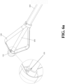
- the above-mentioned detachable connection method can be any conventional detachable connection method (similar to those shown in FIGs. 6a and 6b ), such as snapping, locking, buckling, screwing, etc.
- the operating lever mentioned above may be used to adjust the expanding device to be in the expanded state or the contracted state by the relative movement of stretching or rotating with the expanding device (as shown in FIGs. 4a-4d , 7b , 7c ).
- the operating lever mentioned above may further be a hollow operating lever, and the hollow operating lever inside the expanding device has one or more perforations allowing the medical filler to flow to the porous device through the perforations.
- the perforation can be any form of perforation, such as grooves, pores, etc.
- the operating lever may further include a second detachable mechanism (for example, as shown in FIGs. 1a , 1b , 1c , with numeral 330).
- the second detachable mechanism detaches the expanding device from at least part of the operating lever, and leaves the expanding device and the porous device in the vertebrae.
- the second detachable mechanism may be any conventional detachable mechanism, such as screwing, engaging, locking or buckling, while screwing is preferred.
- the injection method may include: detaching the auxiliary expanding device and the operating lever before infusion, and then connecting the injection tool with the hollow jointing tube for infusion.
- the injection method also may include: detaching the auxiliary expanding device before the infusion, and then connecting the injection tool with the hollow operating lever for infusion.
- the above vertebral fixation device may further include an extension tube (see FIG. 1f , reference numeral 700).
- the extension tube is used together with the injection tool, which is respectively connected with the rear end of the hollow jointing tube or the manipulating end of the operating lever, and connected with the injection tool; the connection can be any conventional connection method, such as snapping, locking, screwing, etc.
- the extension tube may be any conventional extension tube.
- the injection tool can be any conventional injection tool.
- the vertebral fixation device above may further include a blocking device used to connect the fixing end of the expanding device after perfusing or inserting the medical filler completely, and the medical filler is blocked by the blocking device from flowing out or dropping out.
- the connection between the blocking device and the fixing end of the expanding device can be any conventional connection, such as screwing, snapping, locking, buckling, etc., the connection method therein is preferred to be screwing or engaging.
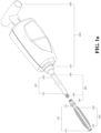
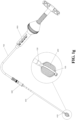
- FIG. 1a is a schematic diagram of a vertebral fixation device according to a preferred specific embodiment of the present invention.
- a porous device 200 is arranged inside an expanding device 100, in which a front end 210 of the porous device and a connecting end 220 of the porous device respectively use a ring-shaped fixing member 250 (not shown in FIG. 1a , refer to FIGs. 1c and 1e ) to connect with a top end 110 of the expanding device and a fixing end 120 of the expanding device, so as to prevent deviation of the porous device 200 due to the excessive infusion pressure of the medical filler during infusion.
- the expanding device 100 is in a contracted state
- the porous device 200 is also in a compressed state.
- the operating lever 300 has a second detachable mechanism 330. After the medical filler is filled into the expanding device 100 and the porous device 200 via the operating lever 300, the expanding device 100 and at least part of the operating lever 300 is detached by way of the second detachable mechanism 330, and the expanding device 100, the porous device 200, and the medical filler are left in the vertebrae.
- An operating end 320 of the operating lever is connected to a jointing end 510 of the auxiliary expanding device 500, and a manipulating end 520 of the auxiliary expanding device carries the operating lever 300 to control the expanding device 100 to expand and contract.
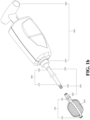
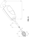
- FIG. 1b is a schematic diagram of the expanding device 100 and the porous device 200 of FIG. 1a in an expanded state. After the expanding device 100 is expanded, the internal porous device 200 automatically expands and fills the space inside the expanding device 100.
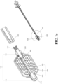
- FIG. 1d is an enlarged cross-sectional view of the expanding device 100, the porous device 200, and the operating lever 300 of FIG. 1a .
- the porous device 200 is used to fix the front end 210 and the connecting end 220 respectively to the top end 110 and the fixing end 120 of the expanding device through the ring-shaped fixing member 250.
- the extension tube 700 can be detached through a detachable connection, and the second detachable mechanism 330 (refer to FIGs. 1a and 1b ) can be used to detach the expanding device 100 and at least part of the operating lever 300, and leave the expanding device 100 and the porous device 200 in vertebrae.
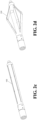
- FIG. 2j illustrates a plane-shaped expanding device 100 in the contracted state.
- FIG. 2k illustrates a plane-shaped expanding device 100 adjusted to be in the expanded state by the operating lever 300.
- FIG. 2l illustrates a blade-shaped expanding device 100 in the contracted state.
- FIG. 2m illustrates the blade-shaped expanding device 100 in the expanding state.
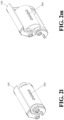
- FIG. 2n illustrates the expanding device 100 in the contracted state.
- FIG. 2o illustrates the expanding device 100 in the expanded state.
- FIG. 3b illustrates the porous device 200 having a hollow interior and a three-dimensional connecting pore structure with uniformly-sized pores 230 on the periphery.
- the medical filler can be injected into the porous device 200 with better fluidity and smoothness, and the flow direction of the medical filler may be controlled through the three-dimensional connecting pore structure on the periphery, and the interdigitate effect of the medical filler may be increased to make closer connection with the vertebrae.
- FIG. 3c illustrates the porous device 200 having three-dimensional connecting pore structures with different porosities.
- the porous device 200 has an the inner layer 260 having a larger porosity and an outer layer 270 having a smaller porosity may be used to increase the smoothness of the medical filler injected to the porous device 200, and reduce the infusion pressure, and the porous device 200 with a smaller porosity in the outer layer 270 is used to effectively achieve interdigitate effect of bone, and to control/limit the flow direction of the medical filler, so as not to cause excessive overflow of the medical filler, which causes danger to the patient.
- FIGs. 4a-4d are schematic diagrams of two expanding methods of a vertebral fixation (methods are not claimed).
- FIGs. 4a-4d illustrate the expanding device 100 extended by the relative stretching motion of the operating lever 300 and the expanding device 100 from the contracted state to the expanded state.
- FIGs. 5a, 5b are respectively schematic diagrams of the connection relationship between two expanding devices 100 and operating lever 300 according to preferred specific embodiments of the present invention.
- FIG. 5a illustrates that the operating lever 300 is connected to the expanding device 100 by the screwed second detachable mechanism 330, so as to inject the medical filler, and then the expanding device 200 is detached from the operating lever 300 or part of the operating lever 300, and the expanding device 100 is left in the vertebrae.
- FIG. 5b illustrates that the operating lever 300 can be connected to the expanding device 100 by the engaged second detachable mechanism 330.
- FIGs. 6a , 6b are schematic diagrams of preferred specific examples of the connection relationship between the tip 110 and the operating lever 300 of the two kinds of expanding devices of the vertebral fixation device of the present invention.
- FIG. 6a illustrates the top end 110 of the expanding device and the operating lever 300 forming a detachable connection by engaging.
- FIG. 6b illustrates the top end 110 of the expanding device and the operating lever 300 forming a detachable connection by screwing.
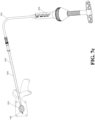
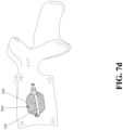
- FIGs. 7a-7d are schematic diagrams of surgical steps of a vertebral fixation device according to the present invention.
- FIG. 7a illustrates the expanding device 100 and the porous device 200, in the contracted state, are placed in the vertebrae.
- FIG. 7b illustrates that the operating lever 300 and the auxiliary expanding device 500 are used to expand the expanding device 100 from the contracted state to the expanded state and expand a space in the vertebrae, the porous device 200 inside the expanding device 100 will expand and fill the space inside the expanding device 100.
- FIG. 7c illustrates that the auxiliary expanding device 500 is detached, and the injection tool 600 and the extension tube 700 are connected, and the medical filler (not shown, refer to FIG.
- FIG. 7d illustrates that the injection tool 600 and the extension tube 700 are detached, and the expanding device 100 is detached from part of the operating lever 300 by the second detachable mechanism 330 of the operating lever 300, and the expanding device 100 and the porous device 200 are left in the vertebrae.
Landscapes
- Health & Medical Sciences (AREA)
- Orthopedic Medicine & Surgery (AREA)
- Life Sciences & Earth Sciences (AREA)
- Surgery (AREA)
- Medical Informatics (AREA)
- General Health & Medical Sciences (AREA)
- Biomedical Technology (AREA)
- Heart & Thoracic Surgery (AREA)
- Nuclear Medicine, Radiotherapy & Molecular Imaging (AREA)
- Molecular Biology (AREA)
- Animal Behavior & Ethology (AREA)
- Engineering & Computer Science (AREA)
- Public Health (AREA)
- Veterinary Medicine (AREA)
- Neurology (AREA)
- Physics & Mathematics (AREA)
- Fluid Mechanics (AREA)
- Prostheses (AREA)
- Surgical Instruments (AREA)
Claims (11)
- Wirbelfixierungsvorrichtung umfassend:eine Spreizvorrichtung (100) aufweisend ein Befestigungsende (120) und ein Oberende (110), wobei die Spreizvorrichtung (100) konfiguriert ist, zwischen einem gespreizten Zustand und einem zusammengezogenen Zustand eingestellt zu werden;undeine dreidimensionale poröse Vorrichtung (200) aufweisend ein Vorderende (210) und ein Verbindungsende (220), wobei das Vorderende (210) der dreidimensionalen porösen Vorrichtung (200) mit dem Oberende (110) der Spreizvorrichtung (100) verbunden ist, und das Verbindungsende (220) der dreidimensionalen porösen Vorrichtung (200) eingerichtet ist, an dem Befestigungsende (120) der Spreizvorrichtung (100) befestigt zu werden;dadurch gekennzeichnet, dass die dreidimensionale poröse Vorrichtung (200) innerhalb der Spreizvorrichtung (100) angeordnet ist,und dass die Spreizvorrichtung (100) und die dreidimensionale poröse Vorrichtung (200) konfiguriert sind, in die Wirbel positioniert zu werden, wobei die Spreizvorrichtung (100) konfiguriert ist, in einen gespreizten Zustand eingestellt zu werden, um einen Raum zu spreizen, und die innerhalb der Spreizvorrichtung (100) befindliche dreidimensionale poröse Vorrichtung (200) konfiguriert ist, sich zu erweitern und den Raum auszufüllen, wobei ein medizinischer Füllstoff (900) in die dreidimensionale poröse Vorrichtung (200) von dem Befestigungsende (120) der Spreizvorrichtung (100) eingefüllt werden kann,und dass die dreidimensionale poröse Vorrichtung (200) konfiguriert ist, eine Fließrichtung und den Infusionsbereich des medizinischen Füllstoffs wirksam zu kontrollieren.
- Wirbelfixierungsvorrichtung nach Anspruch 1, dadurch gekennzeichnet, dass die Wirbelfixierungsvorrichtung ferner einen Bedienungshebel (300) aufweisend ein Verbindungsende (310) und ein Handhabungsende (320) umfasst, wobei das Verbindungsende (310) konfiguriert ist, mit dem Oberende (110) der Spreizvorrichtung (100) verbunden zu werden, und wobei die Spreizvorrichtung (100) konfiguriert ist, durch eine Relativbewegung mit dem Bedienungshebel (300) in den gespreizten oder den zusammengezogenen Zustand eingestellt zu werden.
- Wirbelfixierungsvorrichtung nach Anspruch 2, dadurch gekennzeichnet, dass der Bedienungshebel (300) ein Hohlbedienungshebel (300) ist, und dass der Hohlbedienungshebel (300), der sich innerhalb der Spreizvorrichtung (100) befindet, eine oder mehrere Perforationen (350) aufweist, die konfiguriert sind, dem medizinischen Füllstoff (900) zu erlauben, durch die Perforationen (350) in die dreidimensionale poröse Vorrichtung (200) zu fließen.
- Wirbelfixierungsvorrichtung nach Anspruch 3, dadurch gekennzeichnet, dass die Spreizvorrichtung (100) ferner einen ersten lösbaren Mechanismus (130) umfasst, woraufhin die Spreizvorrichtung (100) konfiguriert ist, von dem Hohlbedienungshebel (300) gelöst zu werden und die Spreizvorrichtung (100) konfiguriert ist, in den Wirbeln zu verbleiben.
- Wirbelfixierungsvorrichtung nach Anspruch 3 oder 4, dadurch gekennzeichnet, dass der Hohlbedienungshebel (300) einen Eingriff- und Fixiermechanismus (340) umfasst, wobei die Spreizvorrichtung (100) konfiguriert ist, durch den Eingriff-und Fixiermechanismus (340) in dem gespreizten Zustand gehalten zu werden.
- Wirbelfixierungsvorrichtung nach Anspruch 1, dadurch gekennzeichnet, dass die Spreizvorrichtung (100) eine laternenförmige Spreizvorrichtung ist.
- Wirbelfixierungsvorrichtung nach Anspruch 1, dadurch gekennzeichnet, dass die dreidimensionale poröse Vorrichtung (200) eine dreidimensionale Verbindung-Porenstruktur ist.
- Wirbelfixierungsvorrichtung nach Anspruch 1, dadurch gekennzeichnet, dass die dreidimensionale poröse Vorrichtung (200) aus einem biologisch abbaubaren Material besteht.
- Wirbelfixierungsvorrichtung nach Anspruch 1, dadurch gekennzeichnet, dass sie ferner umfasst:einen Bedienungshebel (300) aufweisend ein Verbindungsende (310) und ein Hanhabungsende (320), wobei das Verbindungsende (310) für die Verbindung mit dem Oberende (110) der Spreizvorrichtung (100) konfiguriert ist, und wobei die Spreizvorrichtung (100) konfiguriert ist, durch eine Relativbewegung des Bedienugshebels (300) zwischen dem gespreizten Zustand und dem zusammengezogenen Zustand eingestellt zu werden;ein Hohlverbindungsrohr (400) aufweisend ein Vorderende (410) und ein Hinterende (420), wobei das Vorderende (410) des Hohlverbindungsrohr (400) und das Befestigungsende (120) der Spreizvorrichtung (100) eine lösbare Verbindung bilden;eine Hilfsspreizvorrichtung (500) aufweisend ein Verbindungsende (510) und ein Handhabungsende (520), wobei das Verbindungsende (510) der Hilfsspreizvorrichtung (500) und das Hinterende (420) des Hohlverbindungsrohr (400) eine lösbare Verbindung bilden; undein Spritzwerkzeug (600), das für die Verbindung mit dem Hinterende (420) des Hohlverbindungsrohr (400) oder mit dem Handhabungsende (320) des Bedienungshebels (300) eingerichtet ist, und wobei das Spritzwerkzeug (600) eingerichtet ist, den medizinischen Füllstoff (900) durch das Hohlverbindungsrohr (400) oder durch den Bedienungshebel (300) in die dreidimensionale poröse Vorrichtung (200) einzuspritzen;wobei die Hilfsspreizvorrichtung (500) konfiguriert ist, die Spreizvorrichtung (100) mittels des Bedienungshebels (300) zu spreizen, wobei die Hilfsspreizvorrichtung (500) konfiguriert ist, von der gespreizten Spreizvorrichtung gelöst zu werden, und wobei das Spritzwerkzeug (600) konfiguriert ist, mit der gespreizten Spreizvorrichtung installiert werden zu können, um den medizinischen Füllstoff (900) einzufüllen.
- Wirbelfixierungsvorrichtung nach Anspruch 9, dadurch gekennzeichnet, dass der Bedienungshebel (300) einen zweiten lösbaren Mechanismus umfasst, die Spreizvorrichtung (100) konfiguriert ist, von dem Bedienungshebel (300) gelöst zu werden, und die Spreizvorrichtung (100) konfiguriert ist, in den Wirbeln zu verbleiben.
- Wirbelfixierungsvorrichtung nach Anspruch 9 oder 10, dadurch gekennzeichnet, dass der Bedienungshebel (300) ferner einen Fixiermechanismus (340) umfasst, wobei die Spreizvorrichtung (100) konfiguriert ist, durch den Fixiermechanismus (340) in dem gespreizten Zustand gehalten zu werden.
Applications Claiming Priority (1)
| Application Number | Priority Date | Filing Date | Title |
|---|---|---|---|
| TW108127151A TWI731379B (zh) | 2019-07-31 | 2019-07-31 | 椎骨固定裝置 |
Publications (3)
| Publication Number | Publication Date |
|---|---|
| EP3782565A1 EP3782565A1 (de) | 2021-02-24 |
| EP3782565B1 true EP3782565B1 (de) | 2025-05-07 |
| EP3782565C0 EP3782565C0 (de) | 2025-05-07 |
Family
ID=71894714
Family Applications (1)
| Application Number | Title | Priority Date | Filing Date |
|---|---|---|---|
| EP20188689.2A Active EP3782565B1 (de) | 2019-07-31 | 2020-07-30 | Wirbelfixierungsvorrichtung |
Country Status (3)
| Country | Link |
|---|---|
| EP (1) | EP3782565B1 (de) |
| CN (1) | CN112294415B (de) |
| TW (1) | TWI731379B (de) |
Families Citing this family (1)
| Publication number | Priority date | Publication date | Assignee | Title |
|---|---|---|---|---|
| CN114711941A (zh) * | 2021-09-01 | 2022-07-08 | 北京邦塞科技有限公司 | 一种骨填充囊袋及其制备方法 |
Citations (1)
| Publication number | Priority date | Publication date | Assignee | Title |
|---|---|---|---|---|
| US20090182336A1 (en) * | 2008-01-14 | 2009-07-16 | Brenzel Michael P | Apparatus and methods for fracture repair |
Family Cites Families (38)
| Publication number | Priority date | Publication date | Assignee | Title |
|---|---|---|---|---|
| US5514137A (en) | 1993-12-06 | 1996-05-07 | Coutts; Richard D. | Fixation of orthopedic devices |
| ATE361028T1 (de) | 1994-01-26 | 2007-05-15 | Kyphon Inc | Verbesserte aufblasbare vorrichtung zur verwendung in chirurgischen methoden zur fixierung von knochen |
| US6716216B1 (en) | 1998-08-14 | 2004-04-06 | Kyphon Inc. | Systems and methods for treating vertebral bodies |
| US6248110B1 (en) | 1994-01-26 | 2001-06-19 | Kyphon, Inc. | Systems and methods for treating fractured or diseased bone using expandable bodies |
| IL128261A0 (en) | 1999-01-27 | 1999-11-30 | Disc O Tech Medical Tech Ltd | Expandable element |
| US5972015A (en) | 1997-08-15 | 1999-10-26 | Kyphon Inc. | Expandable, asymetric structures for deployment in interior body regions |
| US6354995B1 (en) | 1998-04-24 | 2002-03-12 | Moshe Hoftman | Rotational lateral expander device |
| JP4393706B2 (ja) | 1998-06-01 | 2010-01-06 | カイフォン・ソシエテ・ア・レスポンサビリテ・リミテ | 内部身体領域内の配置のための展開可能な予備形成された構造 |
| US6549995B1 (en) | 2000-01-06 | 2003-04-15 | International Business Machines Corporation | Compressor system memory organization and method for low latency access to uncompressed memory regions |
| JP4883874B2 (ja) | 2000-08-11 | 2012-02-22 | ウォーソー・オーソペディック・インコーポレーテッド | 脊柱を治療する外科用器具及び方法 |
| US6706069B2 (en) * | 2001-09-13 | 2004-03-16 | J. Lee Berger | Spinal grooved director with built in balloon |
| US6748255B2 (en) | 2001-12-14 | 2004-06-08 | Biosense Webster, Inc. | Basket catheter with multiple location sensors |
| TW585091U (en) | 2002-01-31 | 2004-04-21 | A Spine Holding Group Corp | Spine support re-positioning device |
| FR2871366A1 (fr) | 2004-06-09 | 2005-12-16 | Ceravic Soc Par Actions Simpli | Implant expansible prothetique osseux |
| US8425559B2 (en) * | 2004-10-20 | 2013-04-23 | Vertiflex, Inc. | Systems and methods for posterior dynamic stabilization of the spine |
| US8187327B2 (en) * | 2005-05-18 | 2012-05-29 | Kyphon Sarl | Selectively-expandable bone scaffold |
| US8998923B2 (en) | 2005-08-31 | 2015-04-07 | Spinealign Medical, Inc. | Threaded bone filling material plunger |
| US20070067034A1 (en) | 2005-08-31 | 2007-03-22 | Chirico Paul E | Implantable devices and methods for treating micro-architecture deterioration of bone tissue |
| CN100569192C (zh) * | 2005-09-06 | 2009-12-16 | 左适佑 | 骨科用扩孔装置 |
| ZA200804725B (en) * | 2005-12-08 | 2009-03-25 | Synthes Gmbh | Apparatus and methods for treating bone |
| TW200743485A (en) | 2006-05-16 | 2007-12-01 | Spine Asia Co Ltd A | Expandable spine repairing apparatus |
| US20100217335A1 (en) | 2008-12-31 | 2010-08-26 | Chirico Paul E | Self-expanding bone stabilization devices |
| US20090005821A1 (en) | 2007-06-29 | 2009-01-01 | Spineworks Medical, Inc. | Methods and devices for stabilizing bone compatible for use with bone screws |
| TW200833307A (en) | 2007-02-09 | 2008-08-16 | A Spine Holding Group Corp | Medical implant |
| US8224416B2 (en) | 2007-05-09 | 2012-07-17 | St. Jude Medical, Atrial Fibrillation Division, Inc. | Basket catheter having multiple electrodes |
| ES2390482T3 (es) * | 2007-12-28 | 2012-11-13 | Biedermann Technologies Gmbh & Co. Kg | Implante para estabilizar vértebras o huesos |
| US8986386B2 (en) | 2009-03-12 | 2015-03-24 | Vexim Sas | Apparatus for bone restoration of the spine and methods of use |
| TWI392474B (zh) | 2009-10-15 | 2013-04-11 | Spirit Spine Holdings Corp Inc | Bone fixation system |
| US20110196494A1 (en) | 2009-12-04 | 2011-08-11 | Osteo Innovations Llc | Percutaneous interbody spine fusion devices, nuclear support device, spine fracture support device, delivery tools, percutaneous off-angle bone stapling/nailing fixation device and methods of use |
| US20110184447A1 (en) | 2010-01-26 | 2011-07-28 | Warsaw Orthopedic, Inc. | Surgical cutting tool and method |
| CN105769315A (zh) * | 2010-10-21 | 2016-07-20 | 思必瑞特脊椎股份有限公司 | 人工髋关节置换系统 |
| TWI503097B (zh) * | 2012-10-23 | 2015-10-11 | Spirit Spine Holdings Corp Inc | Bone fixation device |
| CN104546085B (zh) * | 2013-10-22 | 2018-02-16 | 思必瑞特脊椎股份有限公司 | 骨固定装置 |
| TWI528938B (zh) * | 2014-03-21 | 2016-04-11 | Spirit Spine Holdings Corp Inc | Bone fixation device |
| TWM541829U (zh) * | 2016-11-22 | 2017-05-21 | Joshua Healthcare Co Ltd | 爪型撐開式內視鏡可操作套組 |
| WO2018195771A1 (zh) | 2017-04-25 | 2018-11-01 | 深圳市大疆创新科技有限公司 | 用于驱动电机转动的控制方法、电子调速器、动力套装和无人飞行器 |
| AU2018279871A1 (en) * | 2017-06-08 | 2020-01-30 | Neuronoff, Inc. | Electrode cured and manufactured in the body, and related methods and devices |
| CN109833122B (zh) * | 2019-03-25 | 2024-11-19 | 广州中医药大学第一附属医院 | 一种脊柱支架 |
-
2019
- 2019-07-31 TW TW108127151A patent/TWI731379B/zh active
-
2020
- 2020-01-14 CN CN202010034450.8A patent/CN112294415B/zh active Active
- 2020-07-30 EP EP20188689.2A patent/EP3782565B1/de active Active
Patent Citations (1)
| Publication number | Priority date | Publication date | Assignee | Title |
|---|---|---|---|---|
| US20090182336A1 (en) * | 2008-01-14 | 2009-07-16 | Brenzel Michael P | Apparatus and methods for fracture repair |
Also Published As
| Publication number | Publication date |
|---|---|
| EP3782565C0 (de) | 2025-05-07 |
| CN112294415A (zh) | 2021-02-02 |
| TWI731379B (zh) | 2021-06-21 |
| TW202106256A (zh) | 2021-02-16 |
| EP3782565A1 (de) | 2021-02-24 |
| CN112294415B (zh) | 2022-07-29 |
Similar Documents
| Publication | Publication Date | Title |
|---|---|---|
| EP2724680B1 (de) | Vorrichtung zur Knochenfixierung | |
| CN101909534B (zh) | 用于稳定椎骨压缩性骨折的多孔包封装置 | |
| EP2010267B1 (de) | Instrumentensatz zur abgabe eines viskosen knochenfüller-materials | |
| EP1509175B1 (de) | Dilatierbares ballonimplantat | |
| EP2209430B1 (de) | Knochenankersystem | |
| US20090054934A1 (en) | Expandable fillers for bone cement | |
| US20150112351A1 (en) | Device for bone fixation | |
| CN101175457A (zh) | 可选择膨胀的骨支架 | |
| EP2419145A2 (de) | Wirbelendplattenverbindungs-implantat und verfahren | |
| CN104546085B (zh) | 骨固定装置 | |
| EP3782565B1 (de) | Wirbelfixierungsvorrichtung | |
| EP2921142B1 (de) | Vorrichtung zur Knochenfixierung | |
| CN105011993B (zh) | 骨固定装置 | |
| EP3771448B1 (de) | Wirbelimplantat | |
| WO2020060524A2 (en) | Suture anchoring systems and methods | |
| TW201236658A (en) | Surgical implant | |
| TWI609669B (zh) | 骨固定裝置 | |
| EP3700437A1 (de) | Vorrichtung und verfahren zum schneiden in eine spongiosa | |
| JP2004515306A (ja) | インプラント、補強要素の導入手順、およびインプラントの製造プロセス |
Legal Events
| Date | Code | Title | Description |
|---|---|---|---|
| PUAI | Public reference made under article 153(3) epc to a published international application that has entered the european phase |
Free format text: ORIGINAL CODE: 0009012 |
|
| STAA | Information on the status of an ep patent application or granted ep patent |
Free format text: STATUS: REQUEST FOR EXAMINATION WAS MADE |
|
| 17P | Request for examination filed |
Effective date: 20200805 |
|
| AK | Designated contracting states |
Kind code of ref document: A1 Designated state(s): AL AT BE BG CH CY CZ DE DK EE ES FI FR GB GR HR HU IE IS IT LI LT LU LV MC MK MT NL NO PL PT RO RS SE SI SK SM TR |
|
| AX | Request for extension of the european patent |
Extension state: BA ME |
|
| STAA | Information on the status of an ep patent application or granted ep patent |
Free format text: STATUS: EXAMINATION IS IN PROGRESS |
|
| 17Q | First examination report despatched |
Effective date: 20231204 |
|
| GRAP | Despatch of communication of intention to grant a patent |
Free format text: ORIGINAL CODE: EPIDOSNIGR1 |
|
| STAA | Information on the status of an ep patent application or granted ep patent |
Free format text: STATUS: GRANT OF PATENT IS INTENDED |
|
| INTG | Intention to grant announced |
Effective date: 20241014 |
|
| RAP1 | Party data changed (applicant data changed or rights of an application transferred) |
Owner name: APCORE MEDICAL TECHNOLOGY CO., LTD. |
|
| GRAJ | Information related to disapproval of communication of intention to grant by the applicant or resumption of examination proceedings by the epo deleted |
Free format text: ORIGINAL CODE: EPIDOSDIGR1 |
|
| STAA | Information on the status of an ep patent application or granted ep patent |
Free format text: STATUS: EXAMINATION IS IN PROGRESS |
|
| GRAS | Grant fee paid |
Free format text: ORIGINAL CODE: EPIDOSNIGR3 |
|
| STAA | Information on the status of an ep patent application or granted ep patent |
Free format text: STATUS: GRANT OF PATENT IS INTENDED |
|
| GRAP | Despatch of communication of intention to grant a patent |
Free format text: ORIGINAL CODE: EPIDOSNIGR1 |
|
| INTC | Intention to grant announced (deleted) | ||
| INTG | Intention to grant announced |
Effective date: 20250217 |
|
| GRAA | (expected) grant |
Free format text: ORIGINAL CODE: 0009210 |
|
| STAA | Information on the status of an ep patent application or granted ep patent |
Free format text: STATUS: THE PATENT HAS BEEN GRANTED |
|
| AK | Designated contracting states |
Kind code of ref document: B1 Designated state(s): AL AT BE BG CH CY CZ DE DK EE ES FI FR GB GR HR HU IE IS IT LI LT LU LV MC MK MT NL NO PL PT RO RS SE SI SK SM TR |
|
| REG | Reference to a national code |
Ref country code: GB Ref legal event code: FG4D |
|
| REG | Reference to a national code |
Ref country code: CH Ref legal event code: EP |
|
| REG | Reference to a national code |
Ref country code: DE Ref legal event code: R096 Ref document number: 602020050729 Country of ref document: DE |
|
| REG | Reference to a national code |
Ref country code: IE Ref legal event code: FG4D |
|
| U01 | Request for unitary effect filed |
Effective date: 20250508 |
|
| U07 | Unitary effect registered |
Designated state(s): AT BE BG DE DK EE FI FR IT LT LU LV MT NL PT RO SE SI Effective date: 20250515 |
|
| U20 | Renewal fee for the european patent with unitary effect paid |
Year of fee payment: 6 Effective date: 20250730 |
|
| PG25 | Lapsed in a contracting state [announced via postgrant information from national office to epo] |
Ref country code: ES Free format text: LAPSE BECAUSE OF FAILURE TO SUBMIT A TRANSLATION OF THE DESCRIPTION OR TO PAY THE FEE WITHIN THE PRESCRIBED TIME-LIMIT Effective date: 20250507 |
|
| PG25 | Lapsed in a contracting state [announced via postgrant information from national office to epo] |
Ref country code: GR Free format text: LAPSE BECAUSE OF FAILURE TO SUBMIT A TRANSLATION OF THE DESCRIPTION OR TO PAY THE FEE WITHIN THE PRESCRIBED TIME-LIMIT Effective date: 20250808 Ref country code: NO Free format text: LAPSE BECAUSE OF FAILURE TO SUBMIT A TRANSLATION OF THE DESCRIPTION OR TO PAY THE FEE WITHIN THE PRESCRIBED TIME-LIMIT Effective date: 20250807 |
|
| PG25 | Lapsed in a contracting state [announced via postgrant information from national office to epo] |
Ref country code: PL Free format text: LAPSE BECAUSE OF FAILURE TO SUBMIT A TRANSLATION OF THE DESCRIPTION OR TO PAY THE FEE WITHIN THE PRESCRIBED TIME-LIMIT Effective date: 20250507 |
|
| PGFP | Annual fee paid to national office [announced via postgrant information from national office to epo] |
Ref country code: GB Payment date: 20250724 Year of fee payment: 6 |
|
| PG25 | Lapsed in a contracting state [announced via postgrant information from national office to epo] |
Ref country code: HR Free format text: LAPSE BECAUSE OF FAILURE TO SUBMIT A TRANSLATION OF THE DESCRIPTION OR TO PAY THE FEE WITHIN THE PRESCRIBED TIME-LIMIT Effective date: 20250507 |
|
| PG25 | Lapsed in a contracting state [announced via postgrant information from national office to epo] |
Ref country code: RS Free format text: LAPSE BECAUSE OF FAILURE TO SUBMIT A TRANSLATION OF THE DESCRIPTION OR TO PAY THE FEE WITHIN THE PRESCRIBED TIME-LIMIT Effective date: 20250807 |
|
| PG25 | Lapsed in a contracting state [announced via postgrant information from national office to epo] |
Ref country code: IS Free format text: LAPSE BECAUSE OF FAILURE TO SUBMIT A TRANSLATION OF THE DESCRIPTION OR TO PAY THE FEE WITHIN THE PRESCRIBED TIME-LIMIT Effective date: 20250907 |
|
| PG25 | Lapsed in a contracting state [announced via postgrant information from national office to epo] |
Ref country code: SM Free format text: LAPSE BECAUSE OF FAILURE TO SUBMIT A TRANSLATION OF THE DESCRIPTION OR TO PAY THE FEE WITHIN THE PRESCRIBED TIME-LIMIT Effective date: 20250507 |
|
| PG25 | Lapsed in a contracting state [announced via postgrant information from national office to epo] |
Ref country code: CZ Free format text: LAPSE BECAUSE OF FAILURE TO SUBMIT A TRANSLATION OF THE DESCRIPTION OR TO PAY THE FEE WITHIN THE PRESCRIBED TIME-LIMIT Effective date: 20250507 |
|
| PG25 | Lapsed in a contracting state [announced via postgrant information from national office to epo] |
Ref country code: SK Free format text: LAPSE BECAUSE OF FAILURE TO SUBMIT A TRANSLATION OF THE DESCRIPTION OR TO PAY THE FEE WITHIN THE PRESCRIBED TIME-LIMIT Effective date: 20250507 |
|
| REG | Reference to a national code |
Ref country code: CH Ref legal event code: H13 Free format text: ST27 STATUS EVENT CODE: U-0-0-H10-H13 (AS PROVIDED BY THE NATIONAL OFFICE) Effective date: 20260224 |
|
| PLBE | No opposition filed within time limit |
Free format text: ORIGINAL CODE: 0009261 |
|
| STAA | Information on the status of an ep patent application or granted ep patent |
Free format text: STATUS: NO OPPOSITION FILED WITHIN TIME LIMIT |
|
| REG | Reference to a national code |
Ref country code: CH Ref legal event code: L10 Free format text: ST27 STATUS EVENT CODE: U-0-0-L10-L00 (AS PROVIDED BY THE NATIONAL OFFICE) Effective date: 20260318 |