EP2010267B1 - Instrumentensatz zur abgabe eines viskosen knochenfüller-materials - Google Patents
Instrumentensatz zur abgabe eines viskosen knochenfüller-materials Download PDFInfo
- Publication number
- EP2010267B1 EP2010267B1 EP07736224A EP07736224A EP2010267B1 EP 2010267 B1 EP2010267 B1 EP 2010267B1 EP 07736224 A EP07736224 A EP 07736224A EP 07736224 A EP07736224 A EP 07736224A EP 2010267 B1 EP2010267 B1 EP 2010267B1
- Authority
- EP
- European Patent Office
- Prior art keywords
- bone
- permeable element
- cannula
- filler
- permeable
- Prior art date
- Legal status (The legal status is an assumption and is not a legal conclusion. Google has not performed a legal analysis and makes no representation as to the accuracy of the status listed.)
- Active
Links
- 210000000988 bone and bone Anatomy 0.000 title claims abstract description 147
- 239000000945 filler Substances 0.000 title claims abstract description 89
- 239000000463 material Substances 0.000 title abstract description 65
- 239000011800 void material Substances 0.000 claims abstract description 62
- 238000002347 injection Methods 0.000 claims description 52
- 239000007924 injection Substances 0.000 claims description 52
- 230000007246 mechanism Effects 0.000 claims description 38
- 238000000605 extraction Methods 0.000 claims description 28
- 239000004744 fabric Substances 0.000 claims description 11
- 239000000835 fiber Substances 0.000 claims description 10
- 239000000560 biocompatible material Substances 0.000 claims description 7
- 229920002994 synthetic fiber Polymers 0.000 claims description 6
- 239000012209 synthetic fiber Substances 0.000 claims description 6
- 229920000914 Metallic fiber Polymers 0.000 claims description 2
- 239000004760 aramid Substances 0.000 claims description 2
- 229920006231 aramid fiber Polymers 0.000 claims description 2
- 238000000034 method Methods 0.000 abstract description 38
- 239000011148 porous material Substances 0.000 abstract description 14
- 239000004568 cement Substances 0.000 description 24
- 238000011282 treatment Methods 0.000 description 17
- 230000015572 biosynthetic process Effects 0.000 description 11
- 239000002639 bone cement Substances 0.000 description 10
- 229910001220 stainless steel Inorganic materials 0.000 description 9
- 239000010935 stainless steel Substances 0.000 description 9
- 206010010214 Compression fracture Diseases 0.000 description 6
- 230000000149 penetrating effect Effects 0.000 description 5
- 229920003229 poly(methyl methacrylate) Polymers 0.000 description 5
- 239000004926 polymethyl methacrylate Substances 0.000 description 5
- 206010017076 Fracture Diseases 0.000 description 4
- 238000001125 extrusion Methods 0.000 description 4
- 239000007943 implant Substances 0.000 description 4
- 238000003780 insertion Methods 0.000 description 4
- 230000037431 insertion Effects 0.000 description 4
- 230000000087 stabilizing effect Effects 0.000 description 4
- 238000001356 surgical procedure Methods 0.000 description 4
- 208000010392 Bone Fractures Diseases 0.000 description 3
- 239000013590 bulk material Substances 0.000 description 3
- 239000012528 membrane Substances 0.000 description 3
- 238000002156 mixing Methods 0.000 description 3
- 239000011345 viscous material Substances 0.000 description 3
- 230000006378 damage Effects 0.000 description 2
- 230000007547 defect Effects 0.000 description 2
- 238000005553 drilling Methods 0.000 description 2
- 239000003814 drug Substances 0.000 description 2
- 238000003384 imaging method Methods 0.000 description 2
- 239000007788 liquid Substances 0.000 description 2
- 239000004033 plastic Substances 0.000 description 2
- 229920003023 plastic Polymers 0.000 description 2
- 230000008439 repair process Effects 0.000 description 2
- 206010041569 spinal fracture Diseases 0.000 description 2
- 241000283707 Capra Species 0.000 description 1
- 208000001132 Osteoporosis Diseases 0.000 description 1
- RTAQQCXQSZGOHL-UHFFFAOYSA-N Titanium Chemical compound [Ti] RTAQQCXQSZGOHL-UHFFFAOYSA-N 0.000 description 1
- 230000005856 abnormality Effects 0.000 description 1
- 230000002411 adverse Effects 0.000 description 1
- 238000013459 approach Methods 0.000 description 1
- 238000005452 bending Methods 0.000 description 1
- 230000008901 benefit Effects 0.000 description 1
- 238000005056 compaction Methods 0.000 description 1
- 238000007906 compression Methods 0.000 description 1
- 230000006835 compression Effects 0.000 description 1
- 238000010276 construction Methods 0.000 description 1
- 230000001419 dependent effect Effects 0.000 description 1
- 238000013461 design Methods 0.000 description 1
- 244000013123 dwarf bean Species 0.000 description 1
- 230000002708 enhancing effect Effects 0.000 description 1
- 230000009969 flowable effect Effects 0.000 description 1
- 238000002594 fluoroscopy Methods 0.000 description 1
- 238000009472 formulation Methods 0.000 description 1
- 230000004927 fusion Effects 0.000 description 1
- 210000000936 intestine Anatomy 0.000 description 1
- 239000007791 liquid phase Substances 0.000 description 1
- 230000013011 mating Effects 0.000 description 1
- 239000012567 medical material Substances 0.000 description 1
- 229910052751 metal Inorganic materials 0.000 description 1
- 239000002184 metal Substances 0.000 description 1
- 238000013508 migration Methods 0.000 description 1
- 230000005012 migration Effects 0.000 description 1
- 239000000203 mixture Substances 0.000 description 1
- 238000012986 modification Methods 0.000 description 1
- 230000004048 modification Effects 0.000 description 1
- HLXZNVUGXRDIFK-UHFFFAOYSA-N nickel titanium Chemical compound [Ti].[Ti].[Ti].[Ti].[Ti].[Ti].[Ti].[Ti].[Ti].[Ti].[Ti].[Ni].[Ni].[Ni].[Ni].[Ni].[Ni].[Ni].[Ni].[Ni].[Ni].[Ni].[Ni].[Ni].[Ni] HLXZNVUGXRDIFK-UHFFFAOYSA-N 0.000 description 1
- 229910001000 nickel titanium Inorganic materials 0.000 description 1
- 210000000056 organ Anatomy 0.000 description 1
- 238000012856 packing Methods 0.000 description 1
- 239000002245 particle Substances 0.000 description 1
- 230000001575 pathological effect Effects 0.000 description 1
- 230000035515 penetration Effects 0.000 description 1
- 230000002093 peripheral effect Effects 0.000 description 1
- 230000001737 promoting effect Effects 0.000 description 1
- 230000005855 radiation Effects 0.000 description 1
- 239000012781 shape memory material Substances 0.000 description 1
- 238000004904 shortening Methods 0.000 description 1
- 230000002459 sustained effect Effects 0.000 description 1
- 210000001519 tissue Anatomy 0.000 description 1
- 239000010936 titanium Substances 0.000 description 1
- 229910052719 titanium Inorganic materials 0.000 description 1
- 238000012546 transfer Methods 0.000 description 1
- 230000003313 weakening effect Effects 0.000 description 1
Images


Classifications
-
- A—HUMAN NECESSITIES
- A61—MEDICAL OR VETERINARY SCIENCE; HYGIENE
- A61B—DIAGNOSIS; SURGERY; IDENTIFICATION
- A61B17/00—Surgical instruments, devices or methods
- A61B17/56—Surgical instruments or methods for treatment of bones or joints; Devices specially adapted therefor
- A61B17/58—Surgical instruments or methods for treatment of bones or joints; Devices specially adapted therefor for osteosynthesis, e.g. bone plates, screws or setting implements
- A61B17/68—Internal fixation devices, including fasteners and spinal fixators, even if a part thereof projects from the skin
- A61B17/70—Spinal positioners or stabilisers, e.g. stabilisers comprising fluid filler in an implant
- A61B17/7097—Stabilisers comprising fluid filler in an implant, e.g. balloon; devices for inserting or filling such implants
- A61B17/7098—Stabilisers comprising fluid filler in an implant, e.g. balloon; devices for inserting or filling such implants wherein the implant is permeable or has openings, e.g. fenestrated screw
-
- A—HUMAN NECESSITIES
- A61—MEDICAL OR VETERINARY SCIENCE; HYGIENE
- A61B—DIAGNOSIS; SURGERY; IDENTIFICATION
- A61B17/00—Surgical instruments, devices or methods
- A61B17/56—Surgical instruments or methods for treatment of bones or joints; Devices specially adapted therefor
- A61B17/58—Surgical instruments or methods for treatment of bones or joints; Devices specially adapted therefor for osteosynthesis, e.g. bone plates, screws or setting implements
- A61B17/88—Osteosynthesis instruments; Methods or means for implanting or extracting internal or external fixation devices
- A61B17/8802—Equipment for handling bone cement or other fluid fillers
- A61B17/8805—Equipment for handling bone cement or other fluid fillers for introducing fluid filler into bone or extracting it
- A61B17/8811—Equipment for handling bone cement or other fluid fillers for introducing fluid filler into bone or extracting it characterised by the introducer tip, i.e. the part inserted into or onto the bone
-
- A—HUMAN NECESSITIES
- A61—MEDICAL OR VETERINARY SCIENCE; HYGIENE
- A61B—DIAGNOSIS; SURGERY; IDENTIFICATION
- A61B17/00—Surgical instruments, devices or methods
- A61B17/56—Surgical instruments or methods for treatment of bones or joints; Devices specially adapted therefor
- A61B17/58—Surgical instruments or methods for treatment of bones or joints; Devices specially adapted therefor for osteosynthesis, e.g. bone plates, screws or setting implements
- A61B17/88—Osteosynthesis instruments; Methods or means for implanting or extracting internal or external fixation devices
- A61B17/8802—Equipment for handling bone cement or other fluid fillers
- A61B17/8805—Equipment for handling bone cement or other fluid fillers for introducing fluid filler into bone or extracting it
- A61B17/8819—Equipment for handling bone cement or other fluid fillers for introducing fluid filler into bone or extracting it characterised by the introducer proximal part, e.g. cannula handle, or by parts which are inserted inside each other, e.g. stylet and cannula
-
- A—HUMAN NECESSITIES
- A61—MEDICAL OR VETERINARY SCIENCE; HYGIENE
- A61B—DIAGNOSIS; SURGERY; IDENTIFICATION
- A61B17/00—Surgical instruments, devices or methods
- A61B17/56—Surgical instruments or methods for treatment of bones or joints; Devices specially adapted therefor
- A61B17/58—Surgical instruments or methods for treatment of bones or joints; Devices specially adapted therefor for osteosynthesis, e.g. bone plates, screws or setting implements
- A61B17/88—Osteosynthesis instruments; Methods or means for implanting or extracting internal or external fixation devices
- A61B17/885—Tools for expanding or compacting bones or discs or cavities therein
- A61B17/8852—Tools for expanding or compacting bones or discs or cavities therein capable of being assembled or enlarged, or changing shape, inside the bone or disc
- A61B17/8855—Tools for expanding or compacting bones or discs or cavities therein capable of being assembled or enlarged, or changing shape, inside the bone or disc inflatable, e.g. kyphoplasty balloons
-
- A—HUMAN NECESSITIES
- A61—MEDICAL OR VETERINARY SCIENCE; HYGIENE
- A61F—FILTERS IMPLANTABLE INTO BLOOD VESSELS; PROSTHESES; DEVICES PROVIDING PATENCY TO, OR PREVENTING COLLAPSING OF, TUBULAR STRUCTURES OF THE BODY, e.g. STENTS; ORTHOPAEDIC, NURSING OR CONTRACEPTIVE DEVICES; FOMENTATION; TREATMENT OR PROTECTION OF EYES OR EARS; BANDAGES, DRESSINGS OR ABSORBENT PADS; FIRST-AID KITS
- A61F2/00—Filters implantable into blood vessels; Prostheses, i.e. artificial substitutes or replacements for parts of the body; Appliances for connecting them with the body; Devices providing patency to, or preventing collapsing of, tubular structures of the body, e.g. stents
- A61F2/02—Prostheses implantable into the body
- A61F2/30—Joints
- A61F2/44—Joints for the spine, e.g. vertebrae, spinal discs
Definitions
- the present invention relates to devices for injection of a viscous material into a living subject.
- This invention particularly relates to devices for filling bone voids.
- This invention more particularly relates to height restoration of a bone, for example, for treating Vertebral Compression Fractures (VCFs).
- VCFs Vertebral Compression Fractures
- a common occurrence in older persons is compression fractures of the vertebrae. This causes pain and a shortening (or other distortion) of stature.
- One common treatment is vertebroplasty, in which cement is injected into a fractured vertebra. While this treatment fixes the fracture and reduces pain, it does not restore the vertebra and person to their original height.
- Another problem with vertebroplasty is that because the cement is injected as a liquid, it may leak outside of the vertebra, for example, through cracks in the vertebra. This may cause considerable bodily harm.
- Viscous cement may reduce the risk of leakage, while sustaining an ability to infiltrate into the intravertebral cancellous bone (interdigitation) [see G Baroud et al, Injection biomechanics of bone cements used in vertebroplasty, Bio-Medical Materials and Engineering 00 (2004) 1-18 ].
- viscous material may reduce the fracture.
- PCT Application No. PCT/IL2006/000239 WO 2006/090379
- This type of bone cement rapidly achieves a high viscosity when its components are mixed and set slowly. The liquid phase is skipped during and immediately following the mixing of the components.
- this procedure provides the advantage of safely skipping the first balloon inflation steps of Scholten, by expanding the bag by introducing fill material, such as a bone repair medium and thereby correcting and stabilizing the bony defect and deformity in a single step. Nevertheless, this procedure is accomplished only by leaving the expanded bag inside the body organ after the injected material has solidified. Furthermore, when the bag is filled with inert filling materials, it is intentionally designed not to allow said material transfer through bag walls.
- US patent publication no. US2002/0058947 discloses a method and apparatus for treating a vertebral body.
- the apparatus comprises a container which is located at the distal end of a fill tube.
- the container and fill tube are carried together with a delivery tube into a surgically prepared cavity.
- Bone filler material is injected through the fill tube into the container, whereupon the container unfurls and conforms to the shape of the cavity.
- the fill tube is then removed from the container, typically when the bone filler material is no longer in a low viscosity state.
- US patent no. US5571189 discloses an expandable fabric implant for stabilizing a spinal motion segment.
- An expandable, porous fabric implant in the form of a bag is inserted into the interior of a reamed out disc, which is packed with material to stabilize the spinal segment.
- the bag is pliable and malleable before its interior space is filled with the material.
- An unexpanded bag is placed in a collapsed, unexpanded state into a bore which opens on to a prepared chamber in the disc, and is then inserted into the chamber.
- the bag is then filled to inflate it to a desired extent, by packing a graft medium into the bag through a guide tube. After the bag has been filled, the guide tube is released from the bag and a fill opening of the bag is closed.
- the present invention provides a device for filling a void in a patient's bone with bone void filler as claimed in claim 1.
- the present invention provides a device by which a bone void filler is introduced into a fractured bone (e.g., vertebral body), while the risk of leakage is minimized.
- a fractured bone e.g., vertebral body
- the device comprises a mechanism having a permeable element secured without releasable threads thereto and a cannula for extending into the bone and for guiding said mechanism to the void.
- a permeable element secured without releasable threads thereto and a cannula for extending into the bone and for guiding said mechanism to the void.
- the permeable element When the permeable element is in a collapsed state it may pass through the cannula and then expand within the bone when the bone void filler is applied under pressure thereto.
- the permeable element is permeable to the bone void filler so that the bone void filler may flow into the void when pressure is applied thereto.
- Some embodiments of the invention may include an injection needle for extending into the permeable element for injecting the bone void filler therein.
- inventions of the invention may also include a pressurizing device for delivering the bone void filler into the permeable element.
- a method of introducing bone void filler into a void in a patient's bone is also disclosed herein.
- the method does not fall within the scope of the claimed invention.
- the method comprises inserting a cannula into the bone, inserting a collapsed permeable element through the cannula into the bone, expanding the permeable element with bone void filler, and then extruding the bone void filler into the bone void by extracting the permeable element through the cannula.
- Another method includes introducing bone void filler into a void in a patient's bone by inserting a cannula into the bone, inserting a mechanism having a collapsed permeable element through the cannula into the bone, wherein the permeable element is secured to the mechanism without threads, applying the bone void filler into the bone through the permeable element, and then extracting the permeable element through the cannula. Additional objects of the present invention will become apparent from the following description.
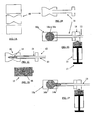
- Figures 1A-F generally illustrate a method for filling bone voids. Such voids may often be a result of a compression fracture and may be treated in accordance with such an exemplary embodiment of the invention.
- X-ray or CT images are usually used for identifying a bone facture.
- a vertebra or other bone may be damaged or fractured by a compression fracture.
- a vertebra may be fractured because of weakening caused by osteoporosis or by other pathological conditions.
- Figure 1A shows a schematic lateral view of a vertebral body 10 having compression fracture.
- access may be minimally invasive.
- Figure 1B shows a guiding cannula 11 inserted into a body, for example, within a fractured vertebral body 10.
- the procedure described herein may use a cannula having a diameter ranging from about 5mm to about 0.5mm.
- a cannula may have a diameter of about 5 mm, about 4 mm, or less in diameter.
- multiple openings into the body may be formed.
- This procedure may alternatively use a surgical or key-hole incision.
- a surgical or key-hole incision may require a longer recuperation period by the patient.
- the cannula (and the corresponding length of a delivery tube described below) may range from about 50mm to about 100mm.
- the cannula may be about 50 mm, about 70 mm, about 100 mm, or more, or intermediate, or smaller values.
- Figure 1C shows a mesh structure 12, comprising an expandable-collapsible permeable element 14 and an extraction mechanism 13. These elements are introduced into guiding cannula 11.
- the permeable element 14 is placed in a optionally preferred location, as chosen by the physician.
- the permeable element 14 is attached to the distal side of the extraction mechanism 13 and is introduced and placed in the body in a collapsed configuration.
- a predetermined amount of bone void filler 16 is prepared. As illustrated in Figure 1D , a filler material reservoir 15 is then filled with the prepared bone void filler.
- the prepared bone void filler material 16 may be prepared for setting into a hardened condition, for example, as in the case of setting bone cement. Alternatively, the prepared bone filler material may be a non-hardening material.
- the bone cement may have an enhanced high-viscosity window before it sets. Its viscosity, although relatively high, may not vary to a degree that adversely affects injection parameters. Alternatively, the viscosity in the window may be about 500, or about 1,000, or about 1,500, or about 2,000 Pascal-sec, or less, or more, or of an intermediate value. In another embodiment of the invention, the working window may be at least about 3 minutes, or at least about 5 minutes, or at least about 8 minutes, or at least about 10 minutes, or at least about 15 minutes, or at least about 20 minutes. The increased viscosity may alternatively provide a short time after mixing of the cement components, for example, zero time (for a pre-provided viscous material).
- the permeable element has at least one flexible segment.
- at least part of the permeable element is a fabric material, whereas said fabric can be woven or non-woven, knitted, braided, molded or be constructed in any other method known in the art.
- at least part of the permeable element is made of a biocompatible material, such as stainless steel, rubber, elastic plastic, synthetic fiber, PMMA, titanium, goat intestine, and the like.
- the permeable element can be formed into an object in the form of sac, bag, cylinder, rectangular column, sphere, torus, kidney-bean configuration, pyramid, cylindrical ellipse, or any combination of such configurations, integrally or by joining separate pieces.
- the permeable element may contain a ray imaging material, such as a metal wire, by which the precise position of the filling member can be easily located by a ray imaging system, such as an X-ray machine.
- the flexible segment and/or fabric material may be of a one-layered or multi-layered construction, depending on the particle size and/or the viscosity of the bone void filler.
- the filler material reservoir is then connected on its distal side to the guided cannula and/or to a mesh structure 12.
- the connection may be accomplished either with or without a special adapter 18.
- the proximal side of the material reservoir may be coupled to an optionally preferred pressurizing device.
- This pressuring device capable of injecting the bone void is schematically illustrated as plunger 17.
- pressure therein increases sufficient for forcing a quantity of bone void filler 16a into the permeable element.
- the bone void filler flows thereto until the permeable element expands to an optionally preferred expanded formation 14a.
- the proximal opening of the guiding cannula or the extraction mechanism may be attached to a syringe and/or to any other bone cement delivery system known in the art.
- the injection port of the guiding cannula or the extraction mechanism may be attached to a distal end of a bone filler reservoir.
- the reservoir may be alternatively attached to a pressurizing hydraulic system on its proximal side.
- the system may be manually operable, and/or by foot, and/or by battery power.
- the pressurizing system may provide sufficient pressure to deliver at least about 5 ml, or at least about 10 ml of viscous bone cement as a single continuous aliquot.
- the pressure source may provide a pressure of about 50, or about 100, or about 150, or about 200, or about 300 atmospheres, or less, or more, or of and intermediate value.
- the system design may assure that the physician's hands are located outside an X-ray radiation zone.
- an actuator for a pressure source may be located about 20 cm, about 40 cm, about 60 cm, about 100 cm, or an intermediate or greater distance from a cement reservoir. Examples of hydraulic delivery devices are thoroughly described in PCT application No. PCT/IL2006/000239 ( WO 2006/090379 ).
- the expansion of the permeable element preferably restores at least part of the height of the vertebra to its former height.
- the expansion may restore, for example, up to about 20%, about 40%, about 60%, about 80%, or intermediate, or higher percentages of a precompression height.
- a particular feature of some embodiments of the invention is that the provided material is of sufficient viscosity or sufficiently solidity for preventing or reducing leakage from the permeable element until the optionally preferred expansion is accomplished, especially as compared with leakage when using liquid PMMA cement.
- the pressure needed to inject the material may be higher than what is typically used in the art to accommodate the increased viscosity.
- the permeable element comprises at least one rigid segment.
- the permeable element may comprise any number of several rigid segments each capable of changing their formation with respect to one another. This may allow the permeable element to expand or collapse under certain preferred circumstances.
- the rigid segments may be set as an expandable telescopic tube.
- the permeable element may comprise of at least one rigid element, elastic or inelastic, capable of stretching, elongating or changing its dimensions in any other way when inner-pressure applied changes.
- the rigid element may be made of shape memory material, such as Nitinol.
- Figure 1F illustrates extraction of the permeable element out of a vertebral body.
- This extraction is accomplished by the extraction mechanism 13.
- the removal of the permeable element forces it to re-collapse.
- the collapsing of the permeable element thereby forces the bone void filler material to penetrate and/or flow through the permeable element walls into the vertebral body until collapsing formation 14b occurs.
- a sufficient force upon the plunger may be applied.
- the amount of filler material that flows through the permeable element walls may form a bulk material 16b.
- the location and/or the volume of the bulk material may be similar to that previously occupied by the permeable element in its expanded formation 16a.
- the bulk material has the properties required for repairing fractures and preserving the height restoration that was achieved by the previous expansion of permeable element 14.
- the tube is removed after the procedure is completed.
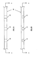
- Figures 2A and 2B illustrate basic extraction mechanisms in accordance with exemplary embodiments of the invention.
- Figure 2A is a cross-sectional view of a mesh structure introducing system, generally comprising an expandable-collapsible permeable element 14 and an extraction mechanism 20 inside the guiding cannula 11.
- the extraction mechanism may comprise several tension wires distally connected to permeable element 14.
- the wires may be elongated ends of threads fabricated into the permeable element walls.
- Figure 2B is a cross-sectional view of a mesh structure introducing system, generally comprising an expandable-collapsible permeable element 14 and an extraction mechanism 21 inside the guiding cannula.
- the extraction mechanism may comprise an elongated body with outside dimensions sufficient for allowing introduction into the guiding cannula.
- the elongated body may be tubular, or hollow, or with slotted areas on its peripheral wall, or any combination thereof.
- Figures 3A and 3B illustrate basic delivery devices in accordance with exemplary embodiments of the invention.
- Figure 3A is a cross-sectional view of a mesh structure introducing system, generally comprising an expandable-collapsible permeable element 14 and an extraction mechanism 13 inside the guiding cannula.
- the bone void filler 30 may be delivered to the permeable element directly through the extraction mechanism.
- the permeable element may comprise a permeable or a leak proof hollow body.
- Figure 3B illustrates a similar apparatus.
- the guiding cannula serves as the delivery device of the bone void filler material.
- the bone void filler material may flow the through location occupied by the extraction mechanism within the guiding cannula, or it may flow in the space created therebetween, depending upon the specific configuration of the extraction mechanism (including the example described with respect to Figs 2A-B ).
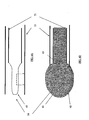
- Figures 4A and 4B show a collapsed formation and an expanded formation of permeable walled structure, respectively, in accordance with exemplary embodiments of the invention.
- Figure 4A is a cross-sectional view of an expandable-collapsible permeable element 14 attached to extraction mechanism 21 inside the guiding cannula.
- the permeable element is shown in its first alternatively preferred collapsed formation 40.
- the permeable element can be positioned inside the guiding cannula either in whole or in part when collapsed until it is placed in the vertebral body prior to the injection of the filler material.
- Dotted line 5-5 shows a section of the permeable element.
- the permeable element wall may contain several through holes 50 or "blind" holes 51. These holes permit flow or extrusion of bone void filler material into cancellous bone and/or into a cavity formed in the vertebral body.
- the diameter of the holes may range from about 0.1mm to about 0.5mm.
- the flow or extrusion from the holes may occur only after the permeable element has expanded to its preferred formation configuration.
- the flow or extrusion may occur only during extraction of the permeable element out of the vertebral body into the distal opening of the cannula.
- the blind hole or holes of the permeable element are preferably closed and may be capable of being burst by the bone void filler when a higher inner-pressure is achieved and after the permeable element has expander to a preferred size or configuration.
- the hole(s) of the permeable element may be open and have certain diameter or size, which permits flowing or exudation of the filler material with certain properties and only after a preferable inner-pressure is met.
- the diameter and size of the holes may vary.
- a hole's diameter and/or shape may be be be changed before, during, or after expansion and/or injection of bone void filler.
- the inner-pressure of the permeable element may be developed when or after the permeable element has expanded to a preferred size or configuration and is extracted from the vertebral body.
- the diameter of the holes may range from about 0.1mm to about 0.5mm.
- the inner-pressures may exceed 20 to 300 Atmospheres.
- the holes may be located in specific areas of the permeable element thereby permitting a flowing of bone void filler to a specific location in vertebral body and/or in a specific flowing direction.
- Fig 4B illustrates another configuration of the permeable element after it has expanded to another preferred expanded formation 41.
- the bone void filler material has filled the volume enclosed by the permeable element and is shown as it emerges through the holes.
- the bone filler material is delivered to the permeable element through an opening port 43.
- Example 1 Using A Perforated Cannula
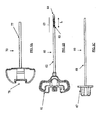
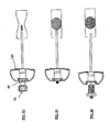
- Figures 6A-6E show an exemplary set of instruments that can be used for VCF treatment.
- the embodiments of the set comprises a guiding cannula 70 (shown in Figure 6A ), a fenestrated cannula 60 (shown in Figure 6B ), and an inner rod/stylet 66 (shown in Figure 6C ).
- the cannula 60 and the inner rod 66 may be assembled (as shown in Figure 6D ) prior to insertion into the body.
- the inner rod 66 may be used, when a further hardening of the cannula is needed (e.g., improved bending durability) during insertion into the bone.
- the guiding cannula 70 generally comprises a handle 77 and a body 78 and may be made of any rigid biocompatible material (e.g. stainless steel).
- the cannula 60 comprises a handle 61 and a body 62 having a distal end 63.
- the cannula 60 may be made of any rigid biocompatible material (e.g. stainless steel).
- the cannula body 78 may be made long enough to reach the inner volume of a vertebra during posterior and/or anterior surgeries.
- a perforated area with plurality of pores 65 may be placed along at least part of the cannula distal end 63.
- the area of the pores has a length L of about 1mm, or about 10mm, or about 20mm, or about 40mm or lesser, or greater, or of intermediate values.
- the area of the pores may cover a full rotation around the longitudinal axis of the cannula 60 (not shown).
- the area of the pores may cover less than a full rotation around the same longitudinal axis (as shown in Figure 6E ).
- the diameter of each pore may be about 0.1mm, or about 0.3mm, or about 0.5mm, or lesser, or greater, or of intermediate values.
- the cannula 60 may be sealed at its distal end, so that the filler material may be delivered only through the pores 65.
- a shaped tip 64 may be incorporated into the cannula's distal end, thus creating a seal therewith.
- the shaped tip may be specifically designed for allowing particular functionality.
- the shaped tip may be designed as a trocar, and/or a driller, and/or a reamer, thus enhancing bone access capabilities of the present invention.
- the inner rod 66 comprises a handle 67 and a rod 68.
- the distal tip of the inner rod and the proximal end of the shaped tip are close to one another (not shown), and optionally in contact.
- the handles 61 and 67 may be capable of being interconnected.
- the assembled set is introduced into a vertebra until a preferred portion of the cannula's distal end has penetrated to the desired location;
- the inner rod is then withdrawn.
- the bone filler material may then be pressurized into the cannula towards its distal end.
- the cannula may be withdrawn from the body.
- the fenestrated cannula 60 may be combined with a longitudinal sleeve cover 110.
- the cannula and the sleeve cover may be connected at least to one point and/or a curve and/or an area. They may be alternatively connected at least at their distal tips. Another alternative may be to crimp the tips together.
- the sleeve cover may be at least partially made from a mesh structure (e.g. knitted/weaved fabric) and/or from a perforated membrane. If a mesh structure is used, it may be appropriate to use fibers having good resistance to tensile strength (e.g. stainless steel, high performance synthetic fibers, etc). Other biocompatible fibers, such as plastic (e.g. PMMA) fibers, may also be used.
- a mesh structure e.g. knitted/weaved fabric
- a perforated membrane e.g. a perforated membrane.
- fibers having good resistance to tensile strength e.g. stainless steel, high performance synthetic fibers, etc.
- Other biocompatible fibers such as plastic (e.g. PMMA) fibers, may also be used.
- the sleeve cover is expanded before and/or during extrusion of the bone filler material into its surroundings. Injection of the bone filler material by embodiments of the present invention promotes homogeneous interdigitation within the bone and/or around the perforated segment.
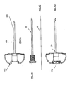
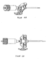
- Figures 7A-7D show another exemplary set of instruments that can be used for VCF treatment.
- the set comprises a cannula 120 (shown in Figure 7A ), a longitudinal sleeve 71 (shown in Figure 7B ), an injection needle 74 (shown in Figure 7C ) and a stylet 75 (shown in Figure 7D ).
- the cannula 120 comprises a handle 121 and a body 122 and may be made of any rigid biocompatible material (e.g. stainless steel).
- the cannula body 122 is long enough to reach the inner volume of a vertebra during posterior and/or anterior surgeries.
- the cannula body 122 is longer than about 50mm, or longer than about 100mm, or longer than about 150 mm.
- the cannula body may be approximately 120mm long.
- the cannula body has an outer diameter of about 2mm, or about 4mm, or about 6mm, or lesser, or greater, or of intermediate values.
- the outer diameter of the cannula body may be approximately 4.2mm.
- the inner diameter of the cannula body may be smaller from its outer diameter by about 0.1mm, or about 0.5mm, or about 2mm.
- the inner diameter of the cannula body may be about 3.6mm.
- the sleeve 71 comprises a handle 73 and a body 72.
- the sleeve body 72 may be at least partially made from a mesh structure (e.g. knitted/weaved fabric) and/or a perforated membrane. If a mesh structure is used, it is most appropriate to use fibers having a good resistance to tensile strength (e.g. stainless steel, high performance synthetic fibers, etc). Other biocompatible fibers, such as PMMA fibers, may also be used.
- the sleeve handle may be coupled to the guiding cannula handle 121.
- the injection needle 74 may be longer than the cannula body 122.
- the stylet 75 may be alternatively longer than the needle 74.
- said delivery system further includes an advance mechanism, capable of advancing and/or withdrawing the sleeve within the guiding cannula along its lumen.
- the advance mechanism may include at least two interconnected elements that permit relative uni-axial motion between them (e.g., a bolt-nut mechanism).
- a bolt-nut mechanism e.g., a bolt-nut mechanism
- one element e.g., a nut
- a second element e.g., a mating bolt
- the sleeve may travel distally or proximally, according to the set relative motion between the at least two interconnected elements.
- steps for filling bone voids are part of a complete exemplary procedure. At least a portion of these steps may be a method of using the invention.
- An example of steps for filling bone voids is:
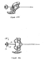
- Figures 8A-8C show an exemplary set of instruments that can be used for VCF treatment.
- the set comprises a cannula 120 (shown in Figure 8A ), an injection element 80 (shown in Figure 8B ), and a stylet 83 (shown in Figure 8C ).
- the cannula 120 comprises a handle 121 and a body 122 and may be made of any rigid biocompatible material (e.g. stainless steel).
- the cannula body 122 is long enough to reach the inner volume of a vertebra during posterior and/or anterior surgeries.
- the cannula body is longer than about 50mm, or longer than about 100mm, or longer than about 150 mm.
- the cannula body may be about 120mm long.
- the cannula body may have an outer diameter of about 2mm, or about 4mm, or about 6mm, or lesser, or greater, or of intermediate values.
- the outer diameter of the cannula body 122 may be approximately 4.2mm.
- the inner diameter of the cannula body 122 may be smaller than its outer diameter by about 0.1mm, or by about 0.5mm, or by about 2mm.
- the inner diameter of the cannula body may alternatively be about 3.6mm.
- the injection element 80 comprises a relatively rigid injection needle 81, covering the sleeve 82 and the sleeve handle 84.
- the injection needle 81 may be coupled to the covering sleeve 82 in at least one spot and/or curve and/or area. Alternatively, they may be coupled to one another at least at their related proximal sides.
- the covering sleeve 82 may be at least partially made from a mesh structure (e.g. knitted/weaved fabric) and/or a perforated membrane. If a mesh structure is used, it is most appropriate to use fibers having good resistance to tensile strength (e.g. stainless steel, high performance synthetic fibers, etc). Other biocompatible fibers, such as PMMA fibers, may be used also.
- the sleeve handle 84 may be coupled to the guiding cannula handle 121.
- the longitudinal body/bodies of the extraction mechanism should be preferably capable of withstanding sufficient tension force needed to overcome existing inner-pressure, drag force, compressive force, or any other combination of forces, in order to re-collapse and extract the permeable element out of the vertebral body, while still being able to force a sufficient quantity of bone void filler through the permeable element wall into the vertebral body.
- the longitudinal body/bodies may be capable of withstanding sufficient compression force for forcing the permeable element into the vertebral body through the guiding cannula.
- the longitudinal body may be the form of a rigid rod.
- the longitudinal body may be in the form of wire or thread.
- the injection needle 81 may alternatively be longer than the cannula body.
- the stylet 83 may alternatively be longer than the needle 81.
- the stylet is capable of stretching the sleeve 82 to a predetermined length along its longitudinal axis when the stylet is introduced therein, optionally through the inner lumen of the injection needle.
- steps for filling bone voids are part of a complete exemplary procedure. At least a portion of these steps may be a method of using the invention.
- An example of steps for filling bone voids is:
- Figures 9A-9C show a set of instruments, at least a portion of which may be used as a part of a bone access kit for accessing or penetrating a vertebra.
- the penetration may include using a posterior and/or an anterior approach.
- the set comprises a guiding cannula 120 (shown in Figure 9A ), a hollow drill 90 (not shown), and/or a regular drill 91 (shown in Figure 9B ), and an optional guide wire 92 (shown in Figure 9C ).
- the instruments may be part of a complete kit for accessing a bone and delivering bone filler material therein.
- they may be used during a vertebroplasty procedure, when preferably, at least one of the exemplary devices of the invention is added.
- the guiding cannula may be later used for guiding the injection element containing bone filler material towards the vertebra.
- the cannula comprises a handle 121 and a body 122 and may be made of any rigid biocompatible material (e.g. stainless steel).
- the cannula body may be long enough to reach the inner volume of a vertebra during posterior and/or anterior surgeries.
- the cannula body may be longer than about 50mm, or longer than about 100mm, or longer than about 150 mm.
- the cannula body may be alternatively about 120mm long.
- the cannula body may have an outer diameter of about 2mm, or about 4mm, or about 6mm, or lesser, or greater, or of an intermediate value.
- the outer diameter of the cannula body may be about 4.2mm.
- the inner diameter of the cannula body may be smaller than its outer diameter by about 0.1mm, or by about 0.5mm, or by about 2mm.
- the inner diameter of the cannula body may alternatively be about 3.6mm.
- the drills that are used in this procedure should preferably be rigid enough when they are inserted into the cannula lumen that they may be capable of protruding out of the lumen. This is so their drilling/reaming tips may properly be used for accessing, and/or penetrating, and/or carving into the bone.
- the guide wire may be any commercially available guide wire, capable of threading through the hollow drill.
- steps for filling bone voids are part of a complete exemplary procedure. At least a portion of these steps may be a method of using the invention.
- An example of steps for filling bone voids is:
- a mesh structure is unable to be extracted out of the bone (e.g., vertebra) under reasonable force
- an alternative method may be applied so that the procedure may still be completed appropriately.
- One optional procedure is to tear a part of the mesh structure off from the whole so as to let it remain within the bone.
- the torn portion to the mesh structure may be considered as an implant which is combined with the solidified filler material within the bone structure.
- at least part of the sleeve or mesh bag may be cut by using a cutting tool specially designed for this purpose.
- the stylet and the injection needle are first removed. As the extractor is removed, the mesh is left within the guiding cannula. The cannula is then removed leaving only the mesh itself. A proximal loose end of the bag may be then cut off with a knife or surgical scissors thus leaving its distal end together with the hardened cement therein within the body. Such a procedure is recommended when it becomes impossible to remove the mesh or bag without damage to the patient.
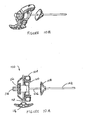
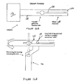
- FIG 10A illustrates a preferred embodiment of a mesh assembly 100 inserted into a working cannula 102.
- the working cannula would be previously inserted and properly located within bone of the patient.
- the working cannula has a handle 104 for ease of control.
- the mesh assembly 100 has a shaft 106.
- the shaft 106 is the longitudinal sleeve, covering both the needle tube and the stylet. It is shown as partially inserted into the bore of the working cannula.
- the mesh assembly has a handle 108 which; in turn, has engagement elements 110 extending therefrom.
- the engagement elements are adapted for engaging and releasably securing the handle of the cannula thereto.
- Such engagement elements may be, for example, detents or other elements.
- the mesh assembly illustrated in Figures 10A and 10B includes both the mesh and an injection needle and is shown with the injection needle secured therein so that only the handle 112 of the injection needle appears.
- the needle tube is located within the longitudinal sleeve 106.
- the tube of the injection needle, together with the stylet, stretches the mesh assembly distally.
- the injection needle is secured to the handle of the mesh assembly, for example, by having threads which screw therein.
- the stylet is also secured by threads therein so that only its knurled knob 114 may be seen in these figures.
- a rotating handle 116 having a shaft 118 is depicted extending through the handle of the mesh assembly.
- the permeable element or mesh is preferably a porous fabric made into a collapsible sack-like arrangement. It is inserted into the bone to be filled through the working cannula. Preferably, it should protrude therein about 20mm.
- the mesh is preferably mounted on the stylet. The stylet should preferably have a blunt leading edge.
- the extraction mechanism and the permeable element may be combined in a single instrument.
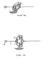
- the stylet when the mesh assembly has been secured to the handle of the properly placed working cannula, preparatory to a cement delivery system being connected to the mesh assembly, the stylet should first be removed. As shown in Figures 11A and 11B , the stylet has a shaft 115. As can now be seen in these figures, the knurled knob of the stylet is adapted to engage the threads 119 which extend from the handle 112 of the injection needle. As can also be seen in these figures, the handle of the mesh assembly has been secured to the handle of the working cannula.
- stylet One main purpose of the stylet is to give extra rigidity for the cannula-mesh assembly and to stretch the sleeve so it will protrude out of cannula distal opening and be located within the vertebra. Afterwards, the stylet should be removed for injecting the bone cement.
- a cement delivery system 120 may be connected to the threads of the injection needle.
- the cement delivery system comprises a plunger 122, which is essentially a cylinder 124 having a piston therein. Extending from the piston is a rod 126 having a handle 128 connected thereto.
- a pressurizing line 130 is connected to the cylinder of the plunger for providing pressure for injecting cement to the bone of the patient.
- a reservoir 132 having a floating piston therein (not shown) is depicted attached to the threads of the injection needle. The reservoir is preferably pre-filled with the prepared cement. The cement is then inserted into the bone of the patient by the pressure supplied by the plunger 122.
- the injection needle may be removed.
- the injection needle 134 has a shaft 136 that is adapted to fit within the bore of the working cannula.
- the injection needle may be secured to the handle of the mesh assembly, for example, by threads 138 adapted for engaging therewith.
- FIGS 15A and 15B depict the rotational handle of the mesh assembly. After the injection needle has been removed from the handle of the mesh assembly, the mesh is preferably extracted from the patient. The mesh is extracted by rotating the rotational handle until it is preferably entirely removed.
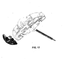
- FIGs 16A and 16B schematically illustrate the operational characteristics of the rotational handle and its engagement with the mesh and the handle of the mesh assembly.
- the shaft 118 of the rotational handle has a slot 120 extending at least a portion along its distal end 122 thereby creating a slitted distal end 124.
- the mesh bag which has been previously described preferably has a loop 130 at its proximal end 132.
- the loop 132 is adapted for engaging the slitted distal end 124 of the shaft of the rotational handle.
- a hole 134 in the bag for allowing the insertion to the cannula or the guide wire therethrough.
- FIG 17 which shows an exploded side view of the engagement of the rotational handle with the handle of the mesh assembly and the bag
- the bag when the rotational handle is rotated the bag is wound upon the shaft 118.
- the bag may be pulled out of the bone of the patient.
- the cement material is extracted from the bag thus leaving the cement remaining within the bone.
- the pressure therein is increased.
- the bag is coupled to only one "tooth" of the slitted distal end of the shaft.
- the bag wraps around both teeth.
- the device of the present invention may comprise a pressurizing device for delivering the bone void filler into said permeable element.
- Said pressurizing device may deliver pressure exceeding about 20 Atm, may deliver pressure exceeding about 100 Atm, and may deliver pressure exceeding about 200 Atm.
- the bone void filler may set into a hardened condition, or the bone void filler may be a non-setting material.
- the mechanism of the device of the present invention may be a needle covered with a mesh.
- Said mesh may comprise metallic fibers.
- Said mesh may comprise synthetic fibers.
- Said mesh may comprise aramid fibers.
- the device of the present invention may have a utility in a method of introducing bone void filler into a void in a patient's bone, comprising:
- the cannula may have a passage therein having an inner diameter of about 2mm or less.
- the cannula may have a passage therein having an inner diameter of about 4mm or less.
- the device of the present invention may have a utility in a method of introducing bone void filler into a void in a patient's bone, comprising:
Landscapes
- Health & Medical Sciences (AREA)
- Orthopedic Medicine & Surgery (AREA)
- Life Sciences & Earth Sciences (AREA)
- Surgery (AREA)
- Medical Informatics (AREA)
- General Health & Medical Sciences (AREA)
- Biomedical Technology (AREA)
- Heart & Thoracic Surgery (AREA)
- Nuclear Medicine, Radiotherapy & Molecular Imaging (AREA)
- Molecular Biology (AREA)
- Animal Behavior & Ethology (AREA)
- Engineering & Computer Science (AREA)
- Public Health (AREA)
- Veterinary Medicine (AREA)
- Neurology (AREA)
- Prostheses (AREA)
- Surgical Instruments (AREA)
- Materials For Medical Uses (AREA)
Claims (15)
- Gerät zum Auffüllen eines Defektes in dem Knochen (10) eines Patienten mit Knochenersatzmaterial (16), das aufweist:a. einen Extraktionsmechanismus (13, 20, 21, 71);b. ein durchlässiges Element (14), das an dem Extraktionsmechanismus ohne lösbare Gewinde gesichert ist; undc. eine Kanüle (11, 120) für das Einführen in den Knochen und zum Führen des Mechanismus zu dem Defekt;wobei das durchlässige Element in einem zusammengelegten Zustand ist, wenn es durch die Kanüle geleitet wird, und sich innerhalb des Knochens aufweitet, wenn das Knochenersatzmaterial unter Druck dahin aufgegeben wird, dadurch gekennzeichnet, dass der Extraktionsmechanismus zum Herausziehen des durchlässigen Elementes aus dem Defekt dient, was das durchlässige Element zwingt, sich wieder zusammenzulegen, so dass das Knochenersatzmaterial gezwungen wird, durch Wände des durchlässigen Elementes in den Defekt zu strömen.
- Gerät nach Anspruch 1, bei dem das durchlässige Element für das Knochenersatzmaterial durchlässig ist, so dass das Knochenersatzmaterial in den Defekt strömen kann, wenn Druck auf dieses ausgeübt wird.
- Gerät nach Anspruch 1, das weiter eine Injektionsnadel (74) zum Einbringen in das durchlässige Element aufweist, um das Knochenersatzmaterial in dieses einzubringen.
- Gerät nach Anspruch 1, das weiter eine Druck ausübende Einheit (15, 17) zum Transportieren des Knochenersatzmaterials in das durchlässige Element aufweist.
- Gerät nach Anspruch 4, bei dem das durchlässige Element dazu ausgelegt ist, den größten Teil des Knochenersatzmaterials in sich zurückzuhalten, bis das durchlässige Element aus der Kanüle zurückgezogen wird.
- Gerät nach Anspruch 5, bei dem Durchlässe des durchlässigen Elementes ungefähr 0.1 mm betragen.
- Gerät nach Anspruch 5, bei dem Durchlässe des durchlässigen Elementes ungefähr 0.3 mm betragen.
- Gerät nach Anspruch 5, bei dem Durchlässe des durchlässigen Elementes ungefähr 0.5 mm betragen.
- Gerät nach Anspruch 5, bei dem das durchlässige Element ein Textil aufweist.
- Gerät nach Anspruch 5, bei dem das durchlässige Element ein biokompatibles Material aufweist.
- Gerät nach Anspruch 5, bei dem das durchlässige Element wenigstens ein starres Segment aufweist.
- Gerät nach Anspruch 1, bei dem das durchlässige Element dauerhaft an dem Mechanismus angebracht ist.
- Gerät nach Anspruch 1, bei dem das durchlässige Element lösbar an dem Mechanismus angebracht ist.
- Gerät nach Anspruch 1, bei dem der Mechanismus eine Nadel ist, die mit einem Netz abgedeckt ist.
- Gerät nach Anspruch 14, bei dem das Netz Fasern aufweist, die aus der Gruppe umfassend metallische Fasern, synthetische Fasern und Aramid-Fasern ausgewählt sind.
Applications Claiming Priority (3)
| Application Number | Priority Date | Filing Date | Title |
|---|---|---|---|
| US79325906P | 2006-04-20 | 2006-04-20 | |
| US82652506P | 2006-09-21 | 2006-09-21 | |
| PCT/IL2007/000484 WO2007122608A2 (en) | 2006-04-20 | 2007-04-17 | Instrumentation kit for delivering viscous bone filler material |
Publications (3)
| Publication Number | Publication Date |
|---|---|
| EP2010267A2 EP2010267A2 (de) | 2009-01-07 |
| EP2010267A4 EP2010267A4 (de) | 2010-12-22 |
| EP2010267B1 true EP2010267B1 (de) | 2011-12-28 |
Family
ID=38625409
Family Applications (1)
| Application Number | Title | Priority Date | Filing Date |
|---|---|---|---|
| EP07736224A Active EP2010267B1 (de) | 2006-04-20 | 2007-04-17 | Instrumentensatz zur abgabe eines viskosen knochenfüller-materials |
Country Status (5)
| Country | Link |
|---|---|
| US (2) | US8147500B2 (de) |
| EP (1) | EP2010267B1 (de) |
| AT (1) | ATE538740T1 (de) |
| ES (1) | ES2376490T3 (de) |
| WO (1) | WO2007122608A2 (de) |
Families Citing this family (18)
| Publication number | Priority date | Publication date | Assignee | Title |
|---|---|---|---|---|
| WO2007122608A2 (en) | 2006-04-20 | 2007-11-01 | Depuy Spine, Inc. | Instrumentation kit for delivering viscous bone filler material |
| US20090240334A1 (en) * | 2008-03-19 | 2009-09-24 | Richelsoph Marc E | Vertebral device for restoration of vertebral body height |
| EP2140823B1 (de) * | 2008-06-23 | 2015-08-26 | National Cancer Center | Stiftanordnung für Operationen |
| US9131970B2 (en) | 2008-06-23 | 2015-09-15 | National Cancer Center | Pin assembly for operation capable of introducing drug |
| EP2361568A1 (de) * | 2008-10-17 | 2011-08-31 | St. Marianna University School of Medicine | Injektionsnadel für knochenzement |
| JP5804325B2 (ja) | 2008-10-30 | 2015-11-04 | デピュイ・シンセス・プロダクツ・インコーポレイテッド | 骨アンカーに骨セメントを送達するためのシステム及び方法 |
| BRPI0924939B8 (pt) * | 2009-06-05 | 2021-06-22 | Weixing Shao | enchimento para coluna vertebral |
| US8870887B2 (en) * | 2009-10-13 | 2014-10-28 | Mark Levatich | Sealing holes in bony cranial anatomy using custom fabricated inserts |
| WO2011082499A1 (en) * | 2010-01-11 | 2011-07-14 | Ao Technology Ag | Cannula and kit for injection of bone cement |
| US8795369B1 (en) | 2010-07-16 | 2014-08-05 | Nuvasive, Inc. | Fracture reduction device and methods |
| US8998925B2 (en) | 2011-06-20 | 2015-04-07 | Rdc Holdings, Llc | Fixation system for orthopedic devices |
| US9155580B2 (en) | 2011-08-25 | 2015-10-13 | Medos International Sarl | Multi-threaded cannulated bone anchors |
| US20130072941A1 (en) | 2011-09-16 | 2013-03-21 | Francisca Tan-Malecki | Cement Injector and Cement Injector Connectors, and Bone Cement Injector Assembly |
| WO2014039998A1 (en) * | 2012-09-07 | 2014-03-13 | Zimmer Knee Creations, Inc. | Subchondral treatment of bone defects with bone-derived implant |
| US9504507B2 (en) * | 2013-07-05 | 2016-11-29 | Tecres S.P.A. | Injector device for introducing biocompatible material into deep anatomical areas |
| AU2017204355B2 (en) | 2016-07-08 | 2021-09-09 | Mako Surgical Corp. | Scaffold for alloprosthetic composite implant |
| KR102037882B1 (ko) * | 2018-03-08 | 2019-10-29 | (주)메디쎄이 | 척추성형용 니들어셈블리 |
| CN109745114A (zh) * | 2018-11-20 | 2019-05-14 | 宁波华科润生物科技有限公司 | 一种多功能的椎体成形器械 |
Family Cites Families (75)
| Publication number | Priority date | Publication date | Assignee | Title |
|---|---|---|---|---|
| US3875595A (en) * | 1974-04-15 | 1975-04-08 | Edward C Froning | Intervertebral disc prosthesis and instruments for locating same |
| US4488549A (en) * | 1981-08-25 | 1984-12-18 | University Of Exeter | Pressurization of cement in bones |
| US4627434A (en) * | 1985-05-03 | 1986-12-09 | Murray William M | Bone cement system and method |
| US5133755A (en) * | 1986-01-28 | 1992-07-28 | Thm Biomedical, Inc. | Method and apparatus for diodegradable, osteogenic, bone graft substitute device |
| US4772287A (en) * | 1987-08-20 | 1988-09-20 | Cedar Surgical, Inc. | Prosthetic disc and method of implanting |
| US4969888A (en) * | 1989-02-09 | 1990-11-13 | Arie Scholten | Surgical protocol for fixation of osteoporotic bone using inflatable device |
| US5015255A (en) * | 1989-05-10 | 1991-05-14 | Spine-Tech, Inc. | Spinal stabilization method |
| US5361752A (en) * | 1991-05-29 | 1994-11-08 | Origin Medsystems, Inc. | Retraction apparatus and methods for endoscopic surgery |
| US5487730A (en) * | 1992-12-30 | 1996-01-30 | Medtronic, Inc. | Balloon catheter with balloon surface retention means |
| US5443514A (en) * | 1993-10-01 | 1995-08-22 | Acromed Corporation | Method for using spinal implants |
| US6248110B1 (en) * | 1994-01-26 | 2001-06-19 | Kyphon, Inc. | Systems and methods for treating fractured or diseased bone using expandable bodies |
| US6241734B1 (en) * | 1998-08-14 | 2001-06-05 | Kyphon, Inc. | Systems and methods for placing materials into bone |
| ATE361028T1 (de) * | 1994-01-26 | 2007-05-15 | Kyphon Inc | Verbesserte aufblasbare vorrichtung zur verwendung in chirurgischen methoden zur fixierung von knochen |
| US7044954B2 (en) * | 1994-01-26 | 2006-05-16 | Kyphon Inc. | Method for treating a vertebral body |
| US6248131B1 (en) * | 1994-05-06 | 2001-06-19 | Advanced Bio Surfaces, Inc. | Articulating joint repair |
| US5888220A (en) * | 1994-05-06 | 1999-03-30 | Advanced Bio Surfaces, Inc. | Articulating joint repair |
| EP0708674B1 (de) * | 1994-05-11 | 2001-11-21 | Baxter International Inc. | Blutsammelsystem |
| US5571189A (en) * | 1994-05-20 | 1996-11-05 | Kuslich; Stephen D. | Expandable fabric implant for stabilizing the spinal motion segment |
| JPH10503667A (ja) * | 1994-05-24 | 1998-04-07 | スミス アンド ネフュー ピーエルシー | 椎間板インプラント |
| US5562736A (en) | 1994-10-17 | 1996-10-08 | Raymedica, Inc. | Method for surgical implantation of a prosthetic spinal disc nucleus |
| AU3795395A (en) * | 1994-11-30 | 1996-06-06 | Ethicon Inc. | Hard tissue bone cements and substitutes |
| US5782919A (en) * | 1995-03-27 | 1998-07-21 | Sdgi Holdings, Inc. | Interbody fusion device and method for restoration of normal spinal anatomy |
| US5702449A (en) * | 1995-06-07 | 1997-12-30 | Danek Medical, Inc. | Reinforced porous spinal implants |
| US5865845A (en) * | 1996-03-05 | 1999-02-02 | Thalgott; John S. | Prosthetic intervertebral disc |
| WO1997037619A1 (de) | 1996-04-10 | 1997-10-16 | Synthes Ag Chur | Zwischenwirbel-implantat |
| US5824084A (en) * | 1996-07-03 | 1998-10-20 | The Cleveland Clinic Foundation | Method of preparing a composite bone graft |
| US5968098A (en) * | 1996-10-22 | 1999-10-19 | Surgical Dynamics, Inc. | Apparatus for fusing adjacent bone structures |
| IL128261A0 (en) | 1999-01-27 | 1999-11-30 | Disc O Tech Medical Tech Ltd | Expandable element |
| US5972015A (en) * | 1997-08-15 | 1999-10-26 | Kyphon Inc. | Expandable, asymetric structures for deployment in interior body regions |
| FR2764795B1 (fr) | 1997-06-19 | 1999-09-10 | Sarl Sra | Cage intersomatique d'immobilisation du rachis et materiel ancillaire associe |
| US6241771B1 (en) * | 1997-08-13 | 2001-06-05 | Cambridge Scientific, Inc. | Resorbable interbody spinal fusion devices |
| US6048346A (en) * | 1997-08-13 | 2000-04-11 | Kyphon Inc. | Systems and methods for injecting flowable materials into bones |
| WO1999049818A1 (en) * | 1998-03-30 | 1999-10-07 | Marchosky J Alexander | Prosthetic system |
| US6171610B1 (en) * | 1998-04-24 | 2001-01-09 | University Of Massachusetts | Guided development and support of hydrogel-cell compositions |
| US6241769B1 (en) * | 1998-05-06 | 2001-06-05 | Cortek, Inc. | Implant for spinal fusion |
| US6719773B1 (en) * | 1998-06-01 | 2004-04-13 | Kyphon Inc. | Expandable structures for deployment in interior body regions |
| US7621950B1 (en) | 1999-01-27 | 2009-11-24 | Kyphon Sarl | Expandable intervertebral spacer |
| US6582446B1 (en) * | 1999-05-06 | 2003-06-24 | J. Alexander Marchosky | Method and apparatus for percutaneous osteoplasty |
| US6048343A (en) * | 1999-06-02 | 2000-04-11 | Mathis; John M. | Bone screw system |
| US6592625B2 (en) * | 1999-10-20 | 2003-07-15 | Anulex Technologies, Inc. | Spinal disc annulus reconstruction method and spinal disc annulus stent |
| US6740093B2 (en) * | 2000-02-28 | 2004-05-25 | Stephen Hochschuler | Method and apparatus for treating a vertebral body |
| US6447514B1 (en) * | 2000-03-07 | 2002-09-10 | Zimmer | Polymer filled hip fracture fixation device |
| US6425923B1 (en) * | 2000-03-07 | 2002-07-30 | Zimmer, Inc. | Contourable polymer filled implant |
| US6332894B1 (en) * | 2000-03-07 | 2001-12-25 | Zimmer, Inc. | Polymer filled spinal fusion cage |
| WO2001076514A2 (en) * | 2000-04-05 | 2001-10-18 | Kyphon Inc. | Methods and devices for treating fractured and/or diseased bone |
| US7025771B2 (en) * | 2000-06-30 | 2006-04-11 | Spineology, Inc. | Tool to direct bone replacement material |
| DE60141653D1 (de) * | 2000-07-21 | 2010-05-06 | Spineology Group Llc | Eine dehnbare, poröse netzbeutel-vorrichtung und seine nutzung in der knochenchirugie |
| WO2002030338A1 (en) | 2000-10-10 | 2002-04-18 | Vertx, Inc. | Method and appartus for treating a vertebral body |
| ATE387163T1 (de) * | 2000-12-15 | 2008-03-15 | Spineology Inc | Annulusverstärkendes band |
| EP1272130B1 (de) | 2001-02-04 | 2004-11-17 | MICHELSON, Gary Karlin | Instrument zum Einführen und Spreiten eines Zwischenwirbelfusionsimplantats |
| US7008433B2 (en) * | 2001-02-15 | 2006-03-07 | Depuy Acromed, Inc. | Vertebroplasty injection device |
| US7544196B2 (en) * | 2001-02-20 | 2009-06-09 | Orthovita, Inc. | System and kit for delivery of restorative materials |
| US6595998B2 (en) * | 2001-03-08 | 2003-07-22 | Spinewave, Inc. | Tissue distraction device |
| US6368351B1 (en) * | 2001-03-27 | 2002-04-09 | Bradley J. Glenn | Intervertebral space implant for use in spinal fusion procedures |
| WO2002087475A1 (en) * | 2001-05-01 | 2002-11-07 | Amedica Corporation | Radiolucent bone graft |
| US20030028251A1 (en) * | 2001-07-30 | 2003-02-06 | Mathews Hallett H. | Methods and devices for interbody spinal stabilization |
| US6679890B2 (en) * | 2001-08-28 | 2004-01-20 | Joseph Y. Margulies | Method and apparatus for augmentation of the femoral neck |
| US6752809B2 (en) * | 2001-12-04 | 2004-06-22 | K2 Medical, Llc | System and method for reinforcing bone in preparation for screw implantation |
| US6730095B2 (en) * | 2002-06-26 | 2004-05-04 | Scimed Life Systems, Inc. | Retrograde plunger delivery system |
| US7320686B2 (en) | 2002-10-09 | 2008-01-22 | Depuy Acromed, Inc. | Device for distracting vertebrae and delivering a flowable material into a disc space |
| US6695760B1 (en) * | 2002-10-11 | 2004-02-24 | Proxima Therapeutics | Treatment of spinal metastases |
| WO2004047689A1 (en) * | 2002-11-21 | 2004-06-10 | Sdgi Holdings, Inc. | Systems and techniques for intravertebral spinal stablization with expandable devices |
| US6875219B2 (en) * | 2003-02-14 | 2005-04-05 | Yves P. Arramon | Bone access system |
| WO2004080357A1 (es) | 2003-03-14 | 2004-09-23 | Ferreyro Irigoyen Roque Humber | Dispositivo hidraulico de inyección de cemento oseo en la vertebroplastiá percutánea |
| US7306610B2 (en) * | 2003-03-21 | 2007-12-11 | Cana Lab Corporation | Method and device for forming a hardened cement in a bone cavity |
| US8415407B2 (en) | 2004-03-21 | 2013-04-09 | Depuy Spine, Inc. | Methods, materials, and apparatus for treating bone and other tissue |
| WO2006011152A2 (en) | 2004-06-17 | 2006-02-02 | Disc-O-Tech Medical Technologies, Ltd. | Methods for treating bone and other tissue |
| US20070032567A1 (en) | 2003-06-17 | 2007-02-08 | Disc-O-Tech Medical | Bone Cement And Methods Of Use Thereof |
| US7250055B1 (en) * | 2003-08-26 | 2007-07-31 | Biomet Manufacturing Corp. | Method and apparatus for cement delivering buttress pin |
| TW200511970A (en) * | 2003-09-29 | 2005-04-01 | Kwan-Ku Lin | A spine wrapping and filling apparatus |
| US7655010B2 (en) | 2003-09-30 | 2010-02-02 | Depuy Spine, Inc. | Vertebral fusion device and method for using same |
| ES2463682T3 (es) | 2005-02-22 | 2014-05-28 | Depuy Spine, Inc. | Cemento óseo |
| IL174347A0 (en) | 2005-07-31 | 2006-08-20 | Disc O Tech Medical Tech Ltd | Bone cement and methods of use thereof |
| US7799035B2 (en) * | 2005-11-18 | 2010-09-21 | Carefusion 2200, Inc. | Device, system and method for delivering a curable material into bone |
| WO2007122608A2 (en) * | 2006-04-20 | 2007-11-01 | Depuy Spine, Inc. | Instrumentation kit for delivering viscous bone filler material |
-
2007
- 2007-04-17 WO PCT/IL2007/000484 patent/WO2007122608A2/en not_active Ceased
- 2007-04-17 US US12/296,538 patent/US8147500B2/en active Active
- 2007-04-17 EP EP07736224A patent/EP2010267B1/de active Active
- 2007-04-17 ES ES07736224T patent/ES2376490T3/es active Active
- 2007-04-17 AT AT07736224T patent/ATE538740T1/de active
-
2012
- 2012-03-13 US US13/418,448 patent/US9277944B2/en active Active
Also Published As
| Publication number | Publication date |
|---|---|
| ES2376490T3 (es) | 2012-03-14 |
| US8147500B2 (en) | 2012-04-03 |
| US20100023017A1 (en) | 2010-01-28 |
| WO2007122608A3 (en) | 2009-04-23 |
| EP2010267A4 (de) | 2010-12-22 |
| US20120226285A1 (en) | 2012-09-06 |
| WO2007122608A2 (en) | 2007-11-01 |
| EP2010267A2 (de) | 2009-01-07 |
| ATE538740T1 (de) | 2012-01-15 |
| US9277944B2 (en) | 2016-03-08 |
Similar Documents
| Publication | Publication Date | Title |
|---|---|---|
| EP2010267B1 (de) | Instrumentensatz zur abgabe eines viskosen knochenfüller-materials | |
| US10751069B2 (en) | Delivery of apparatus and methods for vertebrostening | |
| US20090054934A1 (en) | Expandable fillers for bone cement | |
| AU2009200263B2 (en) | Methods and devices for treating fractured and/or diseased bone | |
| AU2015246133B2 (en) | Systems and methods for vertebral or other bone structure height restoration and stabilization | |
| US8277506B2 (en) | Method and structure for stabilizing a vertebral body | |
| US20030050644A1 (en) | Systems and methods for accessing and treating diseased or fractured bone employing a guide wire | |
| WO2008076357A1 (en) | Delivery apparatus and methods for vertebrostenting | |
| JP2011516149A (ja) | 多層膜補綴用髄核 | |
| CN102573683A (zh) | 前部膨胀球囊 | |
| CN107320173B (zh) | 椎体扩张成形系统和方法 | |
| JP2016532479A (ja) | バルーン補助による椎骨補強システム |
Legal Events
| Date | Code | Title | Description |
|---|---|---|---|
| PUAI | Public reference made under article 153(3) epc to a published international application that has entered the european phase |
Free format text: ORIGINAL CODE: 0009012 |
|
| 17P | Request for examination filed |
Effective date: 20081105 |
|
| AK | Designated contracting states |
Kind code of ref document: A2 Designated state(s): AT BE BG CH CY CZ DE DK EE ES FI FR GB GR HU IE IS IT LI LT LU LV MC MT NL PL PT RO SE SI SK TR |
|
| AX | Request for extension of the european patent |
Extension state: AL BA HR MK RS |
|
| R17D | Deferred search report published (corrected) |
Effective date: 20090423 |
|
| RIC1 | Information provided on ipc code assigned before grant |
Ipc: A61M 31/00 20060101AFI20090428BHEP Ipc: A61B 17/60 20060101ALI20090428BHEP Ipc: A61B 17/58 20060101ALI20090428BHEP |
|
| RIC1 | Information provided on ipc code assigned before grant |
Ipc: A61B 17/58 20060101AFI20090513BHEP Ipc: A61B 17/60 20060101ALI20090513BHEP |
|
| A4 | Supplementary search report drawn up and despatched |
Effective date: 20101119 |
|
| REG | Reference to a national code |
Ref country code: DE Ref legal event code: R079 Ref document number: 602007019678 Country of ref document: DE Free format text: PREVIOUS MAIN CLASS: A61M0031000000 Ipc: A61B0017580000 |
|
| GRAP | Despatch of communication of intention to grant a patent |
Free format text: ORIGINAL CODE: EPIDOSNIGR1 |
|
| RIC1 | Information provided on ipc code assigned before grant |
Ipc: A61B 17/60 20060101ALI20110701BHEP Ipc: A61B 17/58 20060101AFI20110701BHEP |
|
| DAX | Request for extension of the european patent (deleted) | ||
| GRAS | Grant fee paid |
Free format text: ORIGINAL CODE: EPIDOSNIGR3 |
|
| GRAA | (expected) grant |
Free format text: ORIGINAL CODE: 0009210 |
|
| AK | Designated contracting states |
Kind code of ref document: B1 Designated state(s): AT BE BG CH CY CZ DE DK EE ES FI FR GB GR HU IE IS IT LI LT LU LV MC MT NL PL PT RO SE SI SK TR |
|
| REG | Reference to a national code |
Ref country code: GB Ref legal event code: FG4D |
|
| REG | Reference to a national code |
Ref country code: CH Ref legal event code: EP |
|
| REG | Reference to a national code |
Ref country code: AT Ref legal event code: REF Ref document number: 538740 Country of ref document: AT Kind code of ref document: T Effective date: 20120115 |
|
| REG | Reference to a national code |
Ref country code: IE Ref legal event code: FG4D |
|
| REG | Reference to a national code |
Ref country code: DE Ref legal event code: R096 Ref document number: 602007019678 Country of ref document: DE Effective date: 20120308 |
|
| REG | Reference to a national code |
Ref country code: ES Ref legal event code: FG2A Ref document number: 2376490 Country of ref document: ES Kind code of ref document: T3 Effective date: 20120314 |
|
| REG | Reference to a national code |
Ref country code: NL Ref legal event code: VDEP Effective date: 20111228 |
|
| PG25 | Lapsed in a contracting state [announced via postgrant information from national office to epo] |
Ref country code: LT Free format text: LAPSE BECAUSE OF FAILURE TO SUBMIT A TRANSLATION OF THE DESCRIPTION OR TO PAY THE FEE WITHIN THE PRESCRIBED TIME-LIMIT Effective date: 20111228 |
|
| LTIE | Lt: invalidation of european patent or patent extension |
Effective date: 20111228 |
|
| PG25 | Lapsed in a contracting state [announced via postgrant information from national office to epo] |
Ref country code: GR Free format text: LAPSE BECAUSE OF FAILURE TO SUBMIT A TRANSLATION OF THE DESCRIPTION OR TO PAY THE FEE WITHIN THE PRESCRIBED TIME-LIMIT Effective date: 20120329 Ref country code: SE Free format text: LAPSE BECAUSE OF FAILURE TO SUBMIT A TRANSLATION OF THE DESCRIPTION OR TO PAY THE FEE WITHIN THE PRESCRIBED TIME-LIMIT Effective date: 20111228 Ref country code: SI Free format text: LAPSE BECAUSE OF FAILURE TO SUBMIT A TRANSLATION OF THE DESCRIPTION OR TO PAY THE FEE WITHIN THE PRESCRIBED TIME-LIMIT Effective date: 20111228 Ref country code: LV Free format text: LAPSE BECAUSE OF FAILURE TO SUBMIT A TRANSLATION OF THE DESCRIPTION OR TO PAY THE FEE WITHIN THE PRESCRIBED TIME-LIMIT Effective date: 20111228 |
|
| PG25 | Lapsed in a contracting state [announced via postgrant information from national office to epo] |
Ref country code: BE Free format text: LAPSE BECAUSE OF FAILURE TO SUBMIT A TRANSLATION OF THE DESCRIPTION OR TO PAY THE FEE WITHIN THE PRESCRIBED TIME-LIMIT Effective date: 20111228 Ref country code: CY Free format text: LAPSE BECAUSE OF FAILURE TO SUBMIT A TRANSLATION OF THE DESCRIPTION OR TO PAY THE FEE WITHIN THE PRESCRIBED TIME-LIMIT Effective date: 20111228 |
|
| PG25 | Lapsed in a contracting state [announced via postgrant information from national office to epo] |
Ref country code: BG Free format text: LAPSE BECAUSE OF FAILURE TO SUBMIT A TRANSLATION OF THE DESCRIPTION OR TO PAY THE FEE WITHIN THE PRESCRIBED TIME-LIMIT Effective date: 20120328 Ref country code: NL Free format text: LAPSE BECAUSE OF FAILURE TO SUBMIT A TRANSLATION OF THE DESCRIPTION OR TO PAY THE FEE WITHIN THE PRESCRIBED TIME-LIMIT Effective date: 20111228 Ref country code: IS Free format text: LAPSE BECAUSE OF FAILURE TO SUBMIT A TRANSLATION OF THE DESCRIPTION OR TO PAY THE FEE WITHIN THE PRESCRIBED TIME-LIMIT Effective date: 20120428 Ref country code: EE Free format text: LAPSE BECAUSE OF FAILURE TO SUBMIT A TRANSLATION OF THE DESCRIPTION OR TO PAY THE FEE WITHIN THE PRESCRIBED TIME-LIMIT Effective date: 20111228 Ref country code: SK Free format text: LAPSE BECAUSE OF FAILURE TO SUBMIT A TRANSLATION OF THE DESCRIPTION OR TO PAY THE FEE WITHIN THE PRESCRIBED TIME-LIMIT Effective date: 20111228 Ref country code: CZ Free format text: LAPSE BECAUSE OF FAILURE TO SUBMIT A TRANSLATION OF THE DESCRIPTION OR TO PAY THE FEE WITHIN THE PRESCRIBED TIME-LIMIT Effective date: 20111228 |
|
| PG25 | Lapsed in a contracting state [announced via postgrant information from national office to epo] |
Ref country code: PT Free format text: LAPSE BECAUSE OF FAILURE TO SUBMIT A TRANSLATION OF THE DESCRIPTION OR TO PAY THE FEE WITHIN THE PRESCRIBED TIME-LIMIT Effective date: 20120430 Ref country code: PL Free format text: LAPSE BECAUSE OF FAILURE TO SUBMIT A TRANSLATION OF THE DESCRIPTION OR TO PAY THE FEE WITHIN THE PRESCRIBED TIME-LIMIT Effective date: 20111228 Ref country code: RO Free format text: LAPSE BECAUSE OF FAILURE TO SUBMIT A TRANSLATION OF THE DESCRIPTION OR TO PAY THE FEE WITHIN THE PRESCRIBED TIME-LIMIT Effective date: 20111228 |
|
| PG25 | Lapsed in a contracting state [announced via postgrant information from national office to epo] |
Ref country code: DK Free format text: LAPSE BECAUSE OF FAILURE TO SUBMIT A TRANSLATION OF THE DESCRIPTION OR TO PAY THE FEE WITHIN THE PRESCRIBED TIME-LIMIT Effective date: 20111228 |
|
| PLBE | No opposition filed within time limit |
Free format text: ORIGINAL CODE: 0009261 |
|
| STAA | Information on the status of an ep patent application or granted ep patent |
Free format text: STATUS: NO OPPOSITION FILED WITHIN TIME LIMIT |
|
| PG25 | Lapsed in a contracting state [announced via postgrant information from national office to epo] |
Ref country code: MC Free format text: LAPSE BECAUSE OF NON-PAYMENT OF DUE FEES Effective date: 20120430 |
|
| REG | Reference to a national code |
Ref country code: CH Ref legal event code: PL |
|
| 26N | No opposition filed |
Effective date: 20121001 |
|
| REG | Reference to a national code |
Ref country code: IE Ref legal event code: MM4A |
|
| REG | Reference to a national code |
Ref country code: FR Ref legal event code: ST Effective date: 20121228 |
|
| REG | Reference to a national code |
Ref country code: DE Ref legal event code: R097 Ref document number: 602007019678 Country of ref document: DE Effective date: 20121001 |
|
| PG25 | Lapsed in a contracting state [announced via postgrant information from national office to epo] |
Ref country code: CH Free format text: LAPSE BECAUSE OF NON-PAYMENT OF DUE FEES Effective date: 20120430 Ref country code: IE Free format text: LAPSE BECAUSE OF NON-PAYMENT OF DUE FEES Effective date: 20120417 Ref country code: LI Free format text: LAPSE BECAUSE OF NON-PAYMENT OF DUE FEES Effective date: 20120430 |
|
| PG25 | Lapsed in a contracting state [announced via postgrant information from national office to epo] |
Ref country code: FR Free format text: LAPSE BECAUSE OF NON-PAYMENT OF DUE FEES Effective date: 20120430 |
|
| PG25 | Lapsed in a contracting state [announced via postgrant information from national office to epo] |
Ref country code: FI Free format text: LAPSE BECAUSE OF FAILURE TO SUBMIT A TRANSLATION OF THE DESCRIPTION OR TO PAY THE FEE WITHIN THE PRESCRIBED TIME-LIMIT Effective date: 20111228 |
|
| PG25 | Lapsed in a contracting state [announced via postgrant information from national office to epo] |
Ref country code: MT Free format text: LAPSE BECAUSE OF FAILURE TO SUBMIT A TRANSLATION OF THE DESCRIPTION OR TO PAY THE FEE WITHIN THE PRESCRIBED TIME-LIMIT Effective date: 20111228 |
|
| PG25 | Lapsed in a contracting state [announced via postgrant information from national office to epo] |
Ref country code: TR Free format text: LAPSE BECAUSE OF FAILURE TO SUBMIT A TRANSLATION OF THE DESCRIPTION OR TO PAY THE FEE WITHIN THE PRESCRIBED TIME-LIMIT Effective date: 20111228 |
|
| PG25 | Lapsed in a contracting state [announced via postgrant information from national office to epo] |
Ref country code: LU Free format text: LAPSE BECAUSE OF NON-PAYMENT OF DUE FEES Effective date: 20120417 |
|
| PG25 | Lapsed in a contracting state [announced via postgrant information from national office to epo] |
Ref country code: HU Free format text: LAPSE BECAUSE OF FAILURE TO SUBMIT A TRANSLATION OF THE DESCRIPTION OR TO PAY THE FEE WITHIN THE PRESCRIBED TIME-LIMIT Effective date: 20070417 |
|
| PGFP | Annual fee paid to national office [announced via postgrant information from national office to epo] |
Ref country code: ES Payment date: 20150310 Year of fee payment: 9 |
|
| PGFP | Annual fee paid to national office [announced via postgrant information from national office to epo] |
Ref country code: AT Payment date: 20150325 Year of fee payment: 9 |
|
| REG | Reference to a national code |
Ref country code: AT Ref legal event code: MM01 Ref document number: 538740 Country of ref document: AT Kind code of ref document: T Effective date: 20160417 |
|
| PG25 | Lapsed in a contracting state [announced via postgrant information from national office to epo] |
Ref country code: AT Free format text: LAPSE BECAUSE OF NON-PAYMENT OF DUE FEES Effective date: 20160417 |
|
| PG25 | Lapsed in a contracting state [announced via postgrant information from national office to epo] |
Ref country code: ES Free format text: LAPSE BECAUSE OF NON-PAYMENT OF DUE FEES Effective date: 20160418 |
|
| REG | Reference to a national code |
Ref country code: ES Ref legal event code: FD2A Effective date: 20181205 |
|
| PGFP | Annual fee paid to national office [announced via postgrant information from national office to epo] |
Ref country code: IT Payment date: 20230310 Year of fee payment: 17 |
|
| PGFP | Annual fee paid to national office [announced via postgrant information from national office to epo] |
Ref country code: GB Payment date: 20240229 Year of fee payment: 18 |
|
| PGFP | Annual fee paid to national office [announced via postgrant information from national office to epo] |
Ref country code: DE Payment date: 20240306 Year of fee payment: 18 |
|
| PG25 | Lapsed in a contracting state [announced via postgrant information from national office to epo] |
Ref country code: IT Free format text: LAPSE BECAUSE OF NON-PAYMENT OF DUE FEES Effective date: 20240417 |