EP3781425B1 - Procédé de récupération de l'énergie d'un moteur à combustion pendant une montée de rapport et dispositif de commande pour la mise en oeuvre de ce procédé - Google Patents
Procédé de récupération de l'énergie d'un moteur à combustion pendant une montée de rapport et dispositif de commande pour la mise en oeuvre de ce procédé Download PDFInfo
- Publication number
- EP3781425B1 EP3781425B1 EP19720371.4A EP19720371A EP3781425B1 EP 3781425 B1 EP3781425 B1 EP 3781425B1 EP 19720371 A EP19720371 A EP 19720371A EP 3781425 B1 EP3781425 B1 EP 3781425B1
- Authority
- EP
- European Patent Office
- Prior art keywords
- combustion engine
- transmission
- clutch
- sub
- torque
- Prior art date
- Legal status (The legal status is an assumption and is not a legal conclusion. Google has not performed a legal analysis and makes no representation as to the accuracy of the status listed.)
- Active
Links
Images


Classifications
-
- B—PERFORMING OPERATIONS; TRANSPORTING
- B60—VEHICLES IN GENERAL
- B60K—ARRANGEMENT OR MOUNTING OF PROPULSION UNITS OR OF TRANSMISSIONS IN VEHICLES; ARRANGEMENT OR MOUNTING OF PLURAL DIVERSE PRIME-MOVERS IN VEHICLES; AUXILIARY DRIVES FOR VEHICLES; INSTRUMENTATION OR DASHBOARDS FOR VEHICLES; ARRANGEMENTS IN CONNECTION WITH COOLING, AIR INTAKE, GAS EXHAUST OR FUEL SUPPLY OF PROPULSION UNITS IN VEHICLES
- B60K6/00—Arrangement or mounting of plural diverse prime-movers for mutual or common propulsion, e.g. hybrid propulsion systems comprising electric motors and internal combustion engines
- B60K6/20—Arrangement or mounting of plural diverse prime-movers for mutual or common propulsion, e.g. hybrid propulsion systems comprising electric motors and internal combustion engines the prime-movers consisting of electric motors and internal combustion engines, e.g. HEVs
- B60K6/42—Arrangement or mounting of plural diverse prime-movers for mutual or common propulsion, e.g. hybrid propulsion systems comprising electric motors and internal combustion engines the prime-movers consisting of electric motors and internal combustion engines, e.g. HEVs characterised by the architecture of the hybrid electric vehicle
- B60K6/48—Parallel type
-
- B—PERFORMING OPERATIONS; TRANSPORTING
- B60—VEHICLES IN GENERAL
- B60W—CONJOINT CONTROL OF VEHICLE SUB-UNITS OF DIFFERENT TYPE OR DIFFERENT FUNCTION; CONTROL SYSTEMS SPECIALLY ADAPTED FOR HYBRID VEHICLES; ROAD VEHICLE DRIVE CONTROL SYSTEMS FOR PURPOSES NOT RELATED TO THE CONTROL OF A PARTICULAR SUB-UNIT
- B60W10/00—Conjoint control of vehicle sub-units of different type or different function
- B60W10/02—Conjoint control of vehicle sub-units of different type or different function including control of driveline clutches
-
- B—PERFORMING OPERATIONS; TRANSPORTING
- B60—VEHICLES IN GENERAL
- B60W—CONJOINT CONTROL OF VEHICLE SUB-UNITS OF DIFFERENT TYPE OR DIFFERENT FUNCTION; CONTROL SYSTEMS SPECIALLY ADAPTED FOR HYBRID VEHICLES; ROAD VEHICLE DRIVE CONTROL SYSTEMS FOR PURPOSES NOT RELATED TO THE CONTROL OF A PARTICULAR SUB-UNIT
- B60W10/00—Conjoint control of vehicle sub-units of different type or different function
- B60W10/04—Conjoint control of vehicle sub-units of different type or different function including control of propulsion units
- B60W10/06—Conjoint control of vehicle sub-units of different type or different function including control of propulsion units including control of combustion engines
-
- B—PERFORMING OPERATIONS; TRANSPORTING
- B60—VEHICLES IN GENERAL
- B60W—CONJOINT CONTROL OF VEHICLE SUB-UNITS OF DIFFERENT TYPE OR DIFFERENT FUNCTION; CONTROL SYSTEMS SPECIALLY ADAPTED FOR HYBRID VEHICLES; ROAD VEHICLE DRIVE CONTROL SYSTEMS FOR PURPOSES NOT RELATED TO THE CONTROL OF A PARTICULAR SUB-UNIT
- B60W10/00—Conjoint control of vehicle sub-units of different type or different function
- B60W10/04—Conjoint control of vehicle sub-units of different type or different function including control of propulsion units
- B60W10/08—Conjoint control of vehicle sub-units of different type or different function including control of propulsion units including control of electric propulsion units, e.g. motors or generators
-
- B—PERFORMING OPERATIONS; TRANSPORTING
- B60—VEHICLES IN GENERAL
- B60W—CONJOINT CONTROL OF VEHICLE SUB-UNITS OF DIFFERENT TYPE OR DIFFERENT FUNCTION; CONTROL SYSTEMS SPECIALLY ADAPTED FOR HYBRID VEHICLES; ROAD VEHICLE DRIVE CONTROL SYSTEMS FOR PURPOSES NOT RELATED TO THE CONTROL OF A PARTICULAR SUB-UNIT
- B60W10/00—Conjoint control of vehicle sub-units of different type or different function
- B60W10/10—Conjoint control of vehicle sub-units of different type or different function including control of change-speed gearings
- B60W10/11—Stepped gearings
- B60W10/113—Stepped gearings with two input flow paths, e.g. double clutch transmission selection of one of the torque flow paths by the corresponding input clutch
-
- B—PERFORMING OPERATIONS; TRANSPORTING
- B60—VEHICLES IN GENERAL
- B60W—CONJOINT CONTROL OF VEHICLE SUB-UNITS OF DIFFERENT TYPE OR DIFFERENT FUNCTION; CONTROL SYSTEMS SPECIALLY ADAPTED FOR HYBRID VEHICLES; ROAD VEHICLE DRIVE CONTROL SYSTEMS FOR PURPOSES NOT RELATED TO THE CONTROL OF A PARTICULAR SUB-UNIT
- B60W20/00—Control systems specially adapted for hybrid vehicles
- B60W20/30—Control strategies involving selection of transmission gear ratio
-
- B—PERFORMING OPERATIONS; TRANSPORTING
- B60—VEHICLES IN GENERAL
- B60K—ARRANGEMENT OR MOUNTING OF PROPULSION UNITS OR OF TRANSMISSIONS IN VEHICLES; ARRANGEMENT OR MOUNTING OF PLURAL DIVERSE PRIME-MOVERS IN VEHICLES; AUXILIARY DRIVES FOR VEHICLES; INSTRUMENTATION OR DASHBOARDS FOR VEHICLES; ARRANGEMENTS IN CONNECTION WITH COOLING, AIR INTAKE, GAS EXHAUST OR FUEL SUPPLY OF PROPULSION UNITS IN VEHICLES
- B60K6/00—Arrangement or mounting of plural diverse prime-movers for mutual or common propulsion, e.g. hybrid propulsion systems comprising electric motors and internal combustion engines
- B60K6/20—Arrangement or mounting of plural diverse prime-movers for mutual or common propulsion, e.g. hybrid propulsion systems comprising electric motors and internal combustion engines the prime-movers consisting of electric motors and internal combustion engines, e.g. HEVs
- B60K6/42—Arrangement or mounting of plural diverse prime-movers for mutual or common propulsion, e.g. hybrid propulsion systems comprising electric motors and internal combustion engines the prime-movers consisting of electric motors and internal combustion engines, e.g. HEVs characterised by the architecture of the hybrid electric vehicle
- B60K6/48—Parallel type
- B60K2006/4816—Electric machine connected or connectable to gearbox internal shaft
-
- B—PERFORMING OPERATIONS; TRANSPORTING
- B60—VEHICLES IN GENERAL
- B60W—CONJOINT CONTROL OF VEHICLE SUB-UNITS OF DIFFERENT TYPE OR DIFFERENT FUNCTION; CONTROL SYSTEMS SPECIALLY ADAPTED FOR HYBRID VEHICLES; ROAD VEHICLE DRIVE CONTROL SYSTEMS FOR PURPOSES NOT RELATED TO THE CONTROL OF A PARTICULAR SUB-UNIT
- B60W2710/00—Output or target parameters relating to a particular sub-units
- B60W2710/06—Combustion engines, Gas turbines
- B60W2710/0644—Engine speed
-
- Y—GENERAL TAGGING OF NEW TECHNOLOGICAL DEVELOPMENTS; GENERAL TAGGING OF CROSS-SECTIONAL TECHNOLOGIES SPANNING OVER SEVERAL SECTIONS OF THE IPC; TECHNICAL SUBJECTS COVERED BY FORMER USPC CROSS-REFERENCE ART COLLECTIONS [XRACs] AND DIGESTS
- Y02—TECHNOLOGIES OR APPLICATIONS FOR MITIGATION OR ADAPTATION AGAINST CLIMATE CHANGE
- Y02T—CLIMATE CHANGE MITIGATION TECHNOLOGIES RELATED TO TRANSPORTATION
- Y02T10/00—Road transport of goods or passengers
- Y02T10/60—Other road transportation technologies with climate change mitigation effect
- Y02T10/62—Hybrid vehicles
-
- Y—GENERAL TAGGING OF NEW TECHNOLOGICAL DEVELOPMENTS; GENERAL TAGGING OF CROSS-SECTIONAL TECHNOLOGIES SPANNING OVER SEVERAL SECTIONS OF THE IPC; TECHNICAL SUBJECTS COVERED BY FORMER USPC CROSS-REFERENCE ART COLLECTIONS [XRACs] AND DIGESTS
- Y02—TECHNOLOGIES OR APPLICATIONS FOR MITIGATION OR ADAPTATION AGAINST CLIMATE CHANGE
- Y02T—CLIMATE CHANGE MITIGATION TECHNOLOGIES RELATED TO TRANSPORTATION
- Y02T10/00—Road transport of goods or passengers
- Y02T10/80—Technologies aiming to reduce greenhouse gasses emissions common to all road transportation technologies
- Y02T10/92—Energy efficient charging or discharging systems for batteries, ultracapacitors, supercapacitors or double-layer capacitors specially adapted for vehicles
Definitions
- the invention relates to a method for recovering energy from an internal combustion engine during upshifting and to a control unit designed to carry out the method.
- the dual-clutch transmission is capable of automatically engaging and shifting gears when the combustion engine is disconnected. It is thus ready for a start/stop system and an extended coasting function, in which the vehicle coasts freely when the combustion engine is disconnected.
- the electric actuators also enable easy hybridization of the transmission using an additional electric motor.
- the various hybrid powertrains offer the possibility of recovering energy contained in the vehicle during operation in a variety of ways.
- the simplest example is the recovery of energy from the vehicle's braking processes, which returns energy to the drive process with an efficiency of over 80%.
- An internal combustion engine which reduces its speed during upshifts, contains rotational energy that, until now, has simply been converted into heat without being utilized as drag loss.
- combustion is artificially impaired during upshifts by adjusting the ignition angle in order to achieve a dynamic, short-term reduction in the engine's torque. This leads to worse emissions because combustion is no longer optimal.
- the new torque output changes the speed of the combustion engine because the combustion engine is coupled to the electric machine.
- the controller controls the electric motor to reduce the engine's speed. This can be achieved by generating torque in the opposite direction of engine rotation. Because the transmission disconnects the electric motor and the differential during a shift, torque transfer between them is stopped.
- the EP 1 431 623 A1 proposes a method for controlling an electric machine of a series hybrid vehicle.
- the transmission input shaft driven by a drive shaft of the internal combustion engine, is disconnected from the drive shaft during gear shifts.
- DE 10 2010 044 618 A1 shows different upshift and downshift processes in a hybrid vehicle that runs purely on electricity.
- the combustion engine is used as a flywheel without being ignited.
- the object of the invention is to present a method for recovering energy from an internal combustion engine during the upshift process.
- the object is achieved by a method for recovering kinetic energy of an internal combustion engine by reducing the speed of the internal combustion engine during a predetermined time when shifting up a transmission in a vehicle and converting the kinetic energy of the rotation of the internal combustion engine or a drive unit into electrical energy by at least one electrical machine.
- the electric motor can be coupled to a sub-transmission in a dual-clutch transmission with a first and second sub-transmission.
- the energy of the decelerating combustion engine is recovered by applying excessive torque with the second clutch in the second sub-transmission and applying negative torque to the coupled electric motor.
- the goal is to compensate for the excess torque from the clutch as output torque.
- the process start is triggered by the request to shift up.
- the process is stopped when the combustion engine reaches its target speed.
- the problem is solved with a controller designed to carry out the method.
- the controller is an engine controller and/or a transmission controller with respective data exchange.
- FIG 4 A hybrid solution with the integration of an electric motor EM into a dual-clutch transmission is schematically shown.
- the arrangement includes a starter generator 13 as an additional electric machine.
- the solution according to the invention can be implemented both with the hybridization dual-clutch transmission alone and with the starter generator alone.
- the drivetrain 10 includes an internal combustion engine (ICE) VM connected to a starter generator 13. Furthermore, the drivetrain 10 includes a dual-clutch transmission 14, the output side of which is connected to a differential 16. The differential 16 distributes drive power to a left and a right driven wheel 18L, 18R.
- ICE internal combustion engine
- VM starter generator 13
- VM dual-clutch transmission 14
- the differential 16 distributes drive power to a left and a right driven wheel 18L, 18R.
- the dual-clutch transmission 14 includes a first friction clutch 30 and a first sub-transmission TG 1.
- the first sub-transmission TG 1 includes, for example, gear stages N, 1, 3, 5, etc., which are connected by means of schematically indicated clutches 34 can be engaged and disengaged.
- the first friction clutch 30 and the first partial transmission TG 1 form a first power transmission path 36 for transmitting power from the drive motor VM to the differential 16.
- the dual-clutch transmission 14 further includes a second friction clutch 20 and a second sub-transmission TG 2 .
- the second sub-transmission TG 2 includes, for example, the odd gear stages N, 2, 4, 6, and R, which can be engaged and disengaged by means of associated shift clutches 24.
- the second friction clutch 20 and the second sub-transmission TG 2 form a second power transmission path 26 for transmitting drive power from the drive motor VM to the differential 16.
- the drive train 10 includes an electric machine EM, which is connected to a controller 42 for control and power supply.
- the controller 42 can also include power electronics and a battery.
- the electric machine EM is permanently connected to the second sub-transmission TG 2 , for example, by means of a spur gear set or the like.
- the electric machine EM can be connected to the second sub-transmission TG 2 by means of a coupling arrangement.
- connection of the electric machine EM to the second partial transmission TG 2 which has a high gear and a reverse gear, enables electric driving in almost all operating situations.
- the drive train 10 is designed to operate in three different operating modes.
- drive power is generated solely by the drive motor, the internal combustion engine VM.
- Gear shifts occur without interrupting traction by routing drive power via one of the power transmission paths 26, 36, with a gear stage being preselected in the sub-transmission of the other power transmission path.
- a gear change then occurs by transferring the power transmission flow from one path to the other by actuating the friction clutches 20, 30 in an overlapping manner.
- This drive mode is well known in the field of dual-clutch transmissions.
- a second hybrid drive mode can be set up, in which drive power is provided by both the combustion engine VM and the electric motor EM.
- the drive powers can essentially be added together via the summing point at the input of the second sub-transmission TG 2 .
- the electric machine EM recuperates energy via the drive wheels 18 R and 18 L and the second sub-transmission TG 2 .
- the solution is described as it can be represented using a hybridized dual-clutch transmission.
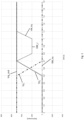
- Fig. 1 shows the upshift situation as it occurs without a special solution for energy recovery in a dual-clutch transmission.
- the two sub-transmissions of the dual-clutch transmission rotate at different speeds.
- the combustion engine VM is initially coupled, starting from time 0, to the first sub-transmission TG 1 , which thus has a torque of, for example, 500 Nm, while the second sub-transmission TG 2 contributes no torque.
- the upshift is triggered at time 0.5 s.
- the speed of the combustion engine is to be increased by the upshift.
- the first clutch 30 is opened and the second clutch 20 is closed.
- the torque of the first partial transmission TG 1 drops to zero by the time 0.7 s, while the torque of the second partial transmission TG 2 increases to the target torque.
- the torque of the combustion engine VM_trq is reduced for a specific period by changing the ignition angle, which is indicated by the curve VM_trq. This influences the air supply and the ignition angle, while the injection rate normally remains constant.
- This intervention in the ignition of the combustion engine is generally achieved by a later ignition angle, whereby the combustion engine operates in a less favorable range and consumes more fuel.
- the combustion engine is braked because it has less torque than the partial transmission TG 2 in the torque reduction range VM_r.
- the electric motor EM in the transmission makes no contribution to the resulting torque trq_out at the wheels, which is indicated by the zero line EM_trq. Furthermore, in most cases, no electric motor is present in the current state of the art.
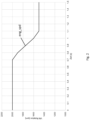
- the speed curve is shown schematically in Figure 2 shown. This graph plots the speed of the internal combustion engine eng_spd over time. At time 0.7 seconds, the torque of the internal combustion engine is reduced, as described above, and the speed of the internal combustion engine is reduced by a partial transmission.
- an electrical machine EM In order to implement the solution according to the invention, an electrical machine EM must be present.
- the combustion engine VM is initially coupled to the first sub-transmission TG 1 starting at time 0, which thus has a torque of, for example, 500 Nm, while the second sub-transmission TG 2 contributes no torque.
- the upshift is triggered again.
- the first clutch 30 is opened, the second clutch 20 is closed.
- the torque of the first sub-transmission TG 1 drops back to zero by time 0.7 s, while the torque of the second sub-transmission TG 2 increases.
- an excessive torque TG 2 _max is set with the second clutch 20, which is maintained for a certain period of time, in the example 0.2 s.
- the electric machine EM is operated with a negative torque EM_trq.
- the combustion engine is used as in Figure 2 shown, braked.
- the location of the electric motor and its connection to the gearbox are not important. The only thing that matters is that the electric motor is to operate with a negative torque and thus use the speed reduction of the combustion engine for recuperation.
- the method according to the invention is implemented in a software solution that can be included in the vehicle control system, more precisely either in an engine control system, a transmission control system or a combination of the controls.
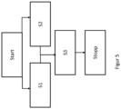
- the method according to the invention is shown schematically in the Figure 5
- the procedure begins with the "Start" block, which is triggered by the upshift request.
- an excessive torque TG 2 _max is set with the second clutch 20 of the second sub-transmission TG 2 , while in S2 the first clutch 30 is opened. At the same time, the torque of the electric machine EM_trq is set to negative.
- step S3 This state is maintained for a short time, as shown in step S3.
- time t which in the example shown is 0.2 seconds, energy is recovered via the electric machine and stored in batteries.
- the process is applicable to various hybrid configurations. It is also possible to arrange the electric motor EM on the input side in front of the transmission or to arrange the electric motor EM at the transmission output with a direct connection to the transmission output shaft.
Landscapes
- Engineering & Computer Science (AREA)
- Chemical & Material Sciences (AREA)
- Combustion & Propulsion (AREA)
- Transportation (AREA)
- Mechanical Engineering (AREA)
- Automation & Control Theory (AREA)
- Hybrid Electric Vehicles (AREA)
- Control Of Transmission Device (AREA)
Claims (4)
- Procédé pour récupérer de l'énergie cinétique d'un moteur à combustion interne (VM) en réduisant la vitesse de rotation du moteur à combustion interne (VM) pendant un temps prédéfini (t) lors du passage d'un rapport de vitesse supérieur (14) dans une transmission de véhicule et en convertissant en énergie électrique l'énergie cinétique de la rotation du moteur à combustion interne (eng_spd) ou d'une unité d'entraînement, au moyen d'au moins une machine électrique (EM, 13), caractérisé en ce que que la machine électrique (EM) est apte à être reliée à une première et une deuxième transmissions partielle (TG1, TG2) dans une boîte de vitesses à double embrayage (14) et à un premier et un deuxième embrayage (20, 30) sur l'une des transmissions partielles (TG1, TG2), en ce que la récupération de l'énergie du moteur à combustion interne (VM) en phase de freinage s'effectue par l'application d'un couple excessif (TG2_max) avec le deuxième embrayage (20) dans la deuxième transmission partielle (TG2) et en appliquant un couple négatif à la machine électrique (EM_tq) reliée.
- Procédé de récupération d'énergie cinétique d'un moteur à combustion interne (VM) selon la revendication 1, caractérisé en ce que le démarrage du procédé (Start) est déclenché par la demande de passage au rapport de vitesse supérieur.
- Procédé de récupération d'énergie cinétique d'un moteur à combustion interne (VM) selon l'une des revendications précédentes, caractérisé en ce que le procédé (Stopp) est arrêté lorsque le moteur à combustion interne (VM) atteint sa vitesse de rotation cible.
- Système de commande conçu pour mettre en œuvre le procédé selon les revendications précédentes, le système de commande (42) étant un système de commande de moteur et/ou un système de commande de transmission avec échange respectif de données.
Applications Claiming Priority (2)
| Application Number | Priority Date | Filing Date | Title |
|---|---|---|---|
| DE102018206130.0A DE102018206130A1 (de) | 2018-04-20 | 2018-04-20 | Verfahren zur Rückgewinnung von Energie des Verbrennungsmotors beim Hochschalten sowie Steuergerät zur Durchführung des Verfahrens |
| PCT/EP2019/058280 WO2019201591A1 (fr) | 2018-04-20 | 2019-04-02 | Procédé de récupération d'énergie du moteur à combustion interne lors de la montée en rapport et appareil de commande pour la mise en œuvre du procédé |
Publications (2)
| Publication Number | Publication Date |
|---|---|
| EP3781425A1 EP3781425A1 (fr) | 2021-02-24 |
| EP3781425B1 true EP3781425B1 (fr) | 2025-06-11 |
Family
ID=66334349
Family Applications (1)
| Application Number | Title | Priority Date | Filing Date |
|---|---|---|---|
| EP19720371.4A Active EP3781425B1 (fr) | 2018-04-20 | 2019-04-02 | Procédé de récupération de l'énergie d'un moteur à combustion pendant une montée de rapport et dispositif de commande pour la mise en oeuvre de ce procédé |
Country Status (4)
| Country | Link |
|---|---|
| EP (1) | EP3781425B1 (fr) |
| CN (1) | CN112004704B (fr) |
| DE (1) | DE102018206130A1 (fr) |
| WO (1) | WO2019201591A1 (fr) |
Citations (3)
| Publication number | Priority date | Publication date | Assignee | Title |
|---|---|---|---|---|
| US20020088290A1 (en) * | 2001-01-10 | 2002-07-11 | Bowen Thomas C. | Twin clutch automated transaxle with motor/generator synchronization |
| EP1262684A1 (fr) * | 2000-03-10 | 2002-12-04 | Hitachi, Ltd. | Transmission automatique, machine dynamoelectrique et voiture |
| EP1559603A1 (fr) * | 2004-01-27 | 2005-08-03 | LuK Lamellen und Kupplungsbau Beteiligungs KG | Procédé de passage de vitesse supérieure dans une boíte de vitesses à deux arbres d'entrée |
Family Cites Families (7)
| Publication number | Priority date | Publication date | Assignee | Title |
|---|---|---|---|---|
| DE19532128A1 (de) * | 1995-08-31 | 1997-03-06 | Clouth Gummiwerke Ag | Antriebssystem, insbesondere für ein Kraftfahrzeug, und Verfahren zum Betreiben desselben |
| FR2848922B1 (fr) * | 2002-12-20 | 2005-12-09 | Recuperation d'energie lors d'un changement de rapport montant sur un vehicule hybride serie | |
| DE102010044618B4 (de) | 2010-08-27 | 2013-10-31 | Getrag Getriebe- Und Zahnradfabrik Hermann Hagenmeyer Gmbh & Cie Kg | Verfahren zum Ansteuern eines Hybrid-Antriebsstranges |
| DE102011106149A1 (de) * | 2011-06-30 | 2013-01-03 | Volkswagen Aktiengesellschaft | Verfahren zum Betrieb eines Kraftfahrzeugs |
| DE102013000838A1 (de) * | 2013-01-21 | 2014-07-24 | Getrag Getriebe- Und Zahnradfabrik Hermann Hagenmeyer Gmbh & Cie Kg | Verfahren zum Halten eines Kraftfahrzeuges an einer Steigung |
| US9956948B2 (en) * | 2016-01-25 | 2018-05-01 | Toyota Motor Engineering & Manufacturing North America, Inc. | Systems and methods for improving gear shifts |
| CN106641233B (zh) * | 2017-02-21 | 2018-09-11 | 周盈裕 | 具有磁力调矩器的双离合变速器及其控制方法 |
-
2018
- 2018-04-20 DE DE102018206130.0A patent/DE102018206130A1/de active Pending
-
2019
- 2019-04-02 EP EP19720371.4A patent/EP3781425B1/fr active Active
- 2019-04-02 CN CN201980027039.3A patent/CN112004704B/zh active Active
- 2019-04-02 WO PCT/EP2019/058280 patent/WO2019201591A1/fr not_active Ceased
Patent Citations (3)
| Publication number | Priority date | Publication date | Assignee | Title |
|---|---|---|---|---|
| EP1262684A1 (fr) * | 2000-03-10 | 2002-12-04 | Hitachi, Ltd. | Transmission automatique, machine dynamoelectrique et voiture |
| US20020088290A1 (en) * | 2001-01-10 | 2002-07-11 | Bowen Thomas C. | Twin clutch automated transaxle with motor/generator synchronization |
| EP1559603A1 (fr) * | 2004-01-27 | 2005-08-03 | LuK Lamellen und Kupplungsbau Beteiligungs KG | Procédé de passage de vitesse supérieure dans une boíte de vitesses à deux arbres d'entrée |
Also Published As
| Publication number | Publication date |
|---|---|
| CN112004704B (zh) | 2023-08-15 |
| WO2019201591A1 (fr) | 2019-10-24 |
| DE102018206130A1 (de) | 2019-10-24 |
| CN112004704A (zh) | 2020-11-27 |
| EP3781425A1 (fr) | 2021-02-24 |
Similar Documents
| Publication | Publication Date | Title |
|---|---|---|
| DE10119503B4 (de) | Verfahren zum Schalten eines Getriebes eines Hybridfahrzeugs | |
| EP2708400B1 (fr) | Procédé destiné à la commande d'une chaîne d'entraînement hybride | |
| DE112006002865B4 (de) | Steuersystem für eine Fahrzeugantriebseinheit | |
| DE19953587B4 (de) | Fahrzeugüberbrückungskupplungssteuerungssystem | |
| DE102008053505B4 (de) | Verfahren zur Steuerung eines Hybridantriebsstrangs eines Kraftfahrzeuges | |
| DE112010001090B4 (de) | Steuerungsvorrichtung für leistungsübertragungsvorrichtung | |
| DE102010016723A1 (de) | Hybridfahrzeug und Steuerverfahren | |
| DE102013002330A1 (de) | Verfahren zum Betreiben eines hybridisierten Doppelkupplungsgetriebe-Antriebsstanges | |
| WO2017060010A1 (fr) | Procédé et dispositif pour faire fonctionner un système de propulsion, système de propulsion | |
| DE102010028071A1 (de) | Verfahren zur Fahrsteuerung eines Kraftfahrzeugs | |
| DE112014003616T5 (de) | Hybridfahrzeug und Steuerungsverfahren für Hybridfahrzeug | |
| DE102013000838A1 (de) | Verfahren zum Halten eines Kraftfahrzeuges an einer Steigung | |
| DE102009045485A1 (de) | Verfahren zum Betreiben einer Antriebsvorrichtung, Antriebsvorrichtung | |
| DE102010022395A1 (de) | Verfahren zum Wechseln der Gangschaltstufen bei einem Hybridantriebssystem | |
| WO2006105929A1 (fr) | Chaine cinematique de vehicule a moteur et procede pour commander une chaine cinematique | |
| DE102017218798A1 (de) | Verfahren zur Steuerung eines Fahrzeugs mit einem Doppelkupplungsgetriebe, sowie Steuergerät und Fahrzeug | |
| DE102009023499A1 (de) | Steuerung eines Hybridantriebssystems | |
| DE112013006935T5 (de) | Vorrichtung zum Steuern eines Hybridfahrzeugs | |
| DE102006054405B4 (de) | Elektrodynamisches Anfahrelement und Verfahren zum Regeln eines elektrodynamischen Anfahrelements | |
| DE102017216984A1 (de) | Verfahren zur Ansteuerung eines Stufengetriebes und eines Antriebsstranges, sowie Steuereinrichtung und Antriebsstrang | |
| DE102009057551A1 (de) | Verfahren zum Betreiben eines Antriebsstrangs in einem Kraftfahrzeug | |
| EP3781425B1 (fr) | Procédé de récupération de l'énergie d'un moteur à combustion pendant une montée de rapport et dispositif de commande pour la mise en oeuvre de ce procédé | |
| EP3556592B1 (fr) | Procédé de récupération d'énergie du moteur à combustion interne ainsi qu'appareil de commande permettant la mise en oeuvre dudit procédé | |
| DE102019220191A1 (de) | Verfahren zum Starten eines Verbrennungsmotors in einem Antriebsstrang mit hybridisiertem Doppelkupplungsgetriebe | |
| DE19758789B4 (de) | Steuervorrichtung für ein Hybridfahrzeug |
Legal Events
| Date | Code | Title | Description |
|---|---|---|---|
| STAA | Information on the status of an ep patent application or granted ep patent |
Free format text: STATUS: UNKNOWN |
|
| STAA | Information on the status of an ep patent application or granted ep patent |
Free format text: STATUS: THE INTERNATIONAL PUBLICATION HAS BEEN MADE |
|
| PUAI | Public reference made under article 153(3) epc to a published international application that has entered the european phase |
Free format text: ORIGINAL CODE: 0009012 |
|
| STAA | Information on the status of an ep patent application or granted ep patent |
Free format text: STATUS: REQUEST FOR EXAMINATION WAS MADE |
|
| 17P | Request for examination filed |
Effective date: 20201022 |
|
| AK | Designated contracting states |
Kind code of ref document: A1 Designated state(s): AL AT BE BG CH CY CZ DE DK EE ES FI FR GB GR HR HU IE IS IT LI LT LU LV MC MK MT NL NO PL PT RO RS SE SI SK SM TR |
|
| AX | Request for extension of the european patent |
Extension state: BA ME |
|
| RIN1 | Information on inventor provided before grant (corrected) |
Inventor name: KNOEPFLE, PHILIPP Inventor name: PROST, JACQUES |
|
| DAV | Request for validation of the european patent (deleted) | ||
| DAX | Request for extension of the european patent (deleted) | ||
| STAA | Information on the status of an ep patent application or granted ep patent |
Free format text: STATUS: EXAMINATION IS IN PROGRESS |
|
| 17Q | First examination report despatched |
Effective date: 20220608 |
|
| GRAP | Despatch of communication of intention to grant a patent |
Free format text: ORIGINAL CODE: EPIDOSNIGR1 |
|
| STAA | Information on the status of an ep patent application or granted ep patent |
Free format text: STATUS: GRANT OF PATENT IS INTENDED |
|
| INTG | Intention to grant announced |
Effective date: 20250117 |
|
| GRAS | Grant fee paid |
Free format text: ORIGINAL CODE: EPIDOSNIGR3 |
|
| GRAA | (expected) grant |
Free format text: ORIGINAL CODE: 0009210 |
|
| STAA | Information on the status of an ep patent application or granted ep patent |
Free format text: STATUS: THE PATENT HAS BEEN GRANTED |
|
| AK | Designated contracting states |
Kind code of ref document: B1 Designated state(s): AL AT BE BG CH CY CZ DE DK EE ES FI FR GB GR HR HU IE IS IT LI LT LU LV MC MK MT NL NO PL PT RO RS SE SI SK SM TR |
|
| REG | Reference to a national code |
Ref country code: GB Ref legal event code: FG4D Free format text: NOT ENGLISH |
|
| REG | Reference to a national code |
Ref country code: CH Ref legal event code: EP |
|
| REG | Reference to a national code |
Ref country code: DE Ref legal event code: R096 Ref document number: 502019013434 Country of ref document: DE |
|
| REG | Reference to a national code |
Ref country code: IE Ref legal event code: FG4D Free format text: LANGUAGE OF EP DOCUMENT: GERMAN |
|
| REG | Reference to a national code |
Ref country code: DE Ref legal event code: R081 Ref document number: 502019013434 Country of ref document: DE Owner name: MAGNA PT B.V. & CO. KGAA, DE Free format text: FORMER OWNER: MAGNA PT B.V. & CO. KG, 74199 UNTERGRUPPENBACH, DE |
|
| PG25 | Lapsed in a contracting state [announced via postgrant information from national office to epo] |
Ref country code: FI Free format text: LAPSE BECAUSE OF FAILURE TO SUBMIT A TRANSLATION OF THE DESCRIPTION OR TO PAY THE FEE WITHIN THE PRESCRIBED TIME-LIMIT Effective date: 20250611 Ref country code: ES Free format text: LAPSE BECAUSE OF FAILURE TO SUBMIT A TRANSLATION OF THE DESCRIPTION OR TO PAY THE FEE WITHIN THE PRESCRIBED TIME-LIMIT Effective date: 20250611 |
|
| REG | Reference to a national code |
Ref country code: LT Ref legal event code: MG9D |
|
| PG25 | Lapsed in a contracting state [announced via postgrant information from national office to epo] |
Ref country code: NO Free format text: LAPSE BECAUSE OF FAILURE TO SUBMIT A TRANSLATION OF THE DESCRIPTION OR TO PAY THE FEE WITHIN THE PRESCRIBED TIME-LIMIT Effective date: 20250911 Ref country code: GR Free format text: LAPSE BECAUSE OF FAILURE TO SUBMIT A TRANSLATION OF THE DESCRIPTION OR TO PAY THE FEE WITHIN THE PRESCRIBED TIME-LIMIT Effective date: 20250912 |
|
| REG | Reference to a national code |
Ref country code: NL Ref legal event code: MP Effective date: 20250611 |
|
| PG25 | Lapsed in a contracting state [announced via postgrant information from national office to epo] |
Ref country code: BG Free format text: LAPSE BECAUSE OF FAILURE TO SUBMIT A TRANSLATION OF THE DESCRIPTION OR TO PAY THE FEE WITHIN THE PRESCRIBED TIME-LIMIT Effective date: 20250611 |
|
| PG25 | Lapsed in a contracting state [announced via postgrant information from national office to epo] |
Ref country code: HR Free format text: LAPSE BECAUSE OF FAILURE TO SUBMIT A TRANSLATION OF THE DESCRIPTION OR TO PAY THE FEE WITHIN THE PRESCRIBED TIME-LIMIT Effective date: 20250611 |
|
| PG25 | Lapsed in a contracting state [announced via postgrant information from national office to epo] |
Ref country code: RS Free format text: LAPSE BECAUSE OF FAILURE TO SUBMIT A TRANSLATION OF THE DESCRIPTION OR TO PAY THE FEE WITHIN THE PRESCRIBED TIME-LIMIT Effective date: 20250911 |
|
| PG25 | Lapsed in a contracting state [announced via postgrant information from national office to epo] |
Ref country code: LV Free format text: LAPSE BECAUSE OF FAILURE TO SUBMIT A TRANSLATION OF THE DESCRIPTION OR TO PAY THE FEE WITHIN THE PRESCRIBED TIME-LIMIT Effective date: 20250611 |
|
| PG25 | Lapsed in a contracting state [announced via postgrant information from national office to epo] |
Ref country code: NL Free format text: LAPSE BECAUSE OF FAILURE TO SUBMIT A TRANSLATION OF THE DESCRIPTION OR TO PAY THE FEE WITHIN THE PRESCRIBED TIME-LIMIT Effective date: 20250611 |
|
| PG25 | Lapsed in a contracting state [announced via postgrant information from national office to epo] |
Ref country code: PT Free format text: LAPSE BECAUSE OF FAILURE TO SUBMIT A TRANSLATION OF THE DESCRIPTION OR TO PAY THE FEE WITHIN THE PRESCRIBED TIME-LIMIT Effective date: 20251013 |
|
| PG25 | Lapsed in a contracting state [announced via postgrant information from national office to epo] |
Ref country code: IS Free format text: LAPSE BECAUSE OF FAILURE TO SUBMIT A TRANSLATION OF THE DESCRIPTION OR TO PAY THE FEE WITHIN THE PRESCRIBED TIME-LIMIT Effective date: 20251011 |
|
| PG25 | Lapsed in a contracting state [announced via postgrant information from national office to epo] |
Ref country code: SM Free format text: LAPSE BECAUSE OF FAILURE TO SUBMIT A TRANSLATION OF THE DESCRIPTION OR TO PAY THE FEE WITHIN THE PRESCRIBED TIME-LIMIT Effective date: 20250611 |