EP3556592B1 - Procédé de récupération d'énergie du moteur à combustion interne ainsi qu'appareil de commande permettant la mise en oeuvre dudit procédé - Google Patents
Procédé de récupération d'énergie du moteur à combustion interne ainsi qu'appareil de commande permettant la mise en oeuvre dudit procédé Download PDFInfo
- Publication number
- EP3556592B1 EP3556592B1 EP19166781.5A EP19166781A EP3556592B1 EP 3556592 B1 EP3556592 B1 EP 3556592B1 EP 19166781 A EP19166781 A EP 19166781A EP 3556592 B1 EP3556592 B1 EP 3556592B1
- Authority
- EP
- European Patent Office
- Prior art keywords
- combustion engine
- transmission
- internal combustion
- energy
- kinetic energy
- Prior art date
- Legal status (The legal status is an assumption and is not a legal conclusion. Google has not performed a legal analysis and makes no representation as to the accuracy of the status listed.)
- Active
Links
Images




Classifications
-
- B—PERFORMING OPERATIONS; TRANSPORTING
- B60—VEHICLES IN GENERAL
- B60K—ARRANGEMENT OR MOUNTING OF PROPULSION UNITS OR OF TRANSMISSIONS IN VEHICLES; ARRANGEMENT OR MOUNTING OF PLURAL DIVERSE PRIME-MOVERS IN VEHICLES; AUXILIARY DRIVES FOR VEHICLES; INSTRUMENTATION OR DASHBOARDS FOR VEHICLES; ARRANGEMENTS IN CONNECTION WITH COOLING, AIR INTAKE, GAS EXHAUST OR FUEL SUPPLY OF PROPULSION UNITS IN VEHICLES
- B60K6/00—Arrangement or mounting of plural diverse prime-movers for mutual or common propulsion, e.g. hybrid propulsion systems comprising electric motors and internal combustion engines
- B60K6/20—Arrangement or mounting of plural diverse prime-movers for mutual or common propulsion, e.g. hybrid propulsion systems comprising electric motors and internal combustion engines the prime-movers consisting of electric motors and internal combustion engines, e.g. HEVs
- B60K6/22—Arrangement or mounting of plural diverse prime-movers for mutual or common propulsion, e.g. hybrid propulsion systems comprising electric motors and internal combustion engines the prime-movers consisting of electric motors and internal combustion engines, e.g. HEVs characterised by apparatus, components or means specially adapted for HEVs
- B60K6/38—Arrangement or mounting of plural diverse prime-movers for mutual or common propulsion, e.g. hybrid propulsion systems comprising electric motors and internal combustion engines the prime-movers consisting of electric motors and internal combustion engines, e.g. HEVs characterised by apparatus, components or means specially adapted for HEVs characterised by the driveline clutches
- B60K6/387—Actuated clutches, i.e. clutches engaged or disengaged by electric, hydraulic or mechanical actuating means
-
- B—PERFORMING OPERATIONS; TRANSPORTING
- B60—VEHICLES IN GENERAL
- B60K—ARRANGEMENT OR MOUNTING OF PROPULSION UNITS OR OF TRANSMISSIONS IN VEHICLES; ARRANGEMENT OR MOUNTING OF PLURAL DIVERSE PRIME-MOVERS IN VEHICLES; AUXILIARY DRIVES FOR VEHICLES; INSTRUMENTATION OR DASHBOARDS FOR VEHICLES; ARRANGEMENTS IN CONNECTION WITH COOLING, AIR INTAKE, GAS EXHAUST OR FUEL SUPPLY OF PROPULSION UNITS IN VEHICLES
- B60K6/00—Arrangement or mounting of plural diverse prime-movers for mutual or common propulsion, e.g. hybrid propulsion systems comprising electric motors and internal combustion engines
- B60K6/20—Arrangement or mounting of plural diverse prime-movers for mutual or common propulsion, e.g. hybrid propulsion systems comprising electric motors and internal combustion engines the prime-movers consisting of electric motors and internal combustion engines, e.g. HEVs
- B60K6/42—Arrangement or mounting of plural diverse prime-movers for mutual or common propulsion, e.g. hybrid propulsion systems comprising electric motors and internal combustion engines the prime-movers consisting of electric motors and internal combustion engines, e.g. HEVs characterised by the architecture of the hybrid electric vehicle
- B60K6/48—Parallel type
-
- B—PERFORMING OPERATIONS; TRANSPORTING
- B60—VEHICLES IN GENERAL
- B60W—CONJOINT CONTROL OF VEHICLE SUB-UNITS OF DIFFERENT TYPE OR DIFFERENT FUNCTION; CONTROL SYSTEMS SPECIALLY ADAPTED FOR HYBRID VEHICLES; ROAD VEHICLE DRIVE CONTROL SYSTEMS FOR PURPOSES NOT RELATED TO THE CONTROL OF A PARTICULAR SUB-UNIT
- B60W10/00—Conjoint control of vehicle sub-units of different type or different function
- B60W10/04—Conjoint control of vehicle sub-units of different type or different function including control of propulsion units
- B60W10/06—Conjoint control of vehicle sub-units of different type or different function including control of propulsion units including control of combustion engines
-
- B—PERFORMING OPERATIONS; TRANSPORTING
- B60—VEHICLES IN GENERAL
- B60W—CONJOINT CONTROL OF VEHICLE SUB-UNITS OF DIFFERENT TYPE OR DIFFERENT FUNCTION; CONTROL SYSTEMS SPECIALLY ADAPTED FOR HYBRID VEHICLES; ROAD VEHICLE DRIVE CONTROL SYSTEMS FOR PURPOSES NOT RELATED TO THE CONTROL OF A PARTICULAR SUB-UNIT
- B60W10/00—Conjoint control of vehicle sub-units of different type or different function
- B60W10/04—Conjoint control of vehicle sub-units of different type or different function including control of propulsion units
- B60W10/08—Conjoint control of vehicle sub-units of different type or different function including control of propulsion units including control of electric propulsion units, e.g. motors or generators
-
- B—PERFORMING OPERATIONS; TRANSPORTING
- B60—VEHICLES IN GENERAL
- B60W—CONJOINT CONTROL OF VEHICLE SUB-UNITS OF DIFFERENT TYPE OR DIFFERENT FUNCTION; CONTROL SYSTEMS SPECIALLY ADAPTED FOR HYBRID VEHICLES; ROAD VEHICLE DRIVE CONTROL SYSTEMS FOR PURPOSES NOT RELATED TO THE CONTROL OF A PARTICULAR SUB-UNIT
- B60W10/00—Conjoint control of vehicle sub-units of different type or different function
- B60W10/10—Conjoint control of vehicle sub-units of different type or different function including control of change-speed gearings
- B60W10/11—Stepped gearings
- B60W10/113—Stepped gearings with two input flow paths, e.g. double clutch transmission selection of one of the torque flow paths by the corresponding input clutch
-
- B—PERFORMING OPERATIONS; TRANSPORTING
- B60—VEHICLES IN GENERAL
- B60W—CONJOINT CONTROL OF VEHICLE SUB-UNITS OF DIFFERENT TYPE OR DIFFERENT FUNCTION; CONTROL SYSTEMS SPECIALLY ADAPTED FOR HYBRID VEHICLES; ROAD VEHICLE DRIVE CONTROL SYSTEMS FOR PURPOSES NOT RELATED TO THE CONTROL OF A PARTICULAR SUB-UNIT
- B60W20/00—Control systems specially adapted for hybrid vehicles
- B60W20/10—Controlling the power contribution of each of the prime movers to meet required power demand
- B60W20/13—Controlling the power contribution of each of the prime movers to meet required power demand in order to stay within battery power input or output limits; in order to prevent overcharging or battery depletion
-
- B—PERFORMING OPERATIONS; TRANSPORTING
- B60—VEHICLES IN GENERAL
- B60W—CONJOINT CONTROL OF VEHICLE SUB-UNITS OF DIFFERENT TYPE OR DIFFERENT FUNCTION; CONTROL SYSTEMS SPECIALLY ADAPTED FOR HYBRID VEHICLES; ROAD VEHICLE DRIVE CONTROL SYSTEMS FOR PURPOSES NOT RELATED TO THE CONTROL OF A PARTICULAR SUB-UNIT
- B60W20/00—Control systems specially adapted for hybrid vehicles
- B60W20/10—Controlling the power contribution of each of the prime movers to meet required power demand
- B60W20/15—Control strategies specially adapted for achieving a particular effect
- B60W20/16—Control strategies specially adapted for achieving a particular effect for reducing engine exhaust emissions
-
- B—PERFORMING OPERATIONS; TRANSPORTING
- B60—VEHICLES IN GENERAL
- B60W—CONJOINT CONTROL OF VEHICLE SUB-UNITS OF DIFFERENT TYPE OR DIFFERENT FUNCTION; CONTROL SYSTEMS SPECIALLY ADAPTED FOR HYBRID VEHICLES; ROAD VEHICLE DRIVE CONTROL SYSTEMS FOR PURPOSES NOT RELATED TO THE CONTROL OF A PARTICULAR SUB-UNIT
- B60W20/00—Control systems specially adapted for hybrid vehicles
- B60W20/40—Controlling the engagement or disengagement of prime movers, e.g. for transition between prime movers
-
- Y—GENERAL TAGGING OF NEW TECHNOLOGICAL DEVELOPMENTS; GENERAL TAGGING OF CROSS-SECTIONAL TECHNOLOGIES SPANNING OVER SEVERAL SECTIONS OF THE IPC; TECHNICAL SUBJECTS COVERED BY FORMER USPC CROSS-REFERENCE ART COLLECTIONS [XRACs] AND DIGESTS
- Y02—TECHNOLOGIES OR APPLICATIONS FOR MITIGATION OR ADAPTATION AGAINST CLIMATE CHANGE
- Y02T—CLIMATE CHANGE MITIGATION TECHNOLOGIES RELATED TO TRANSPORTATION
- Y02T10/00—Road transport of goods or passengers
- Y02T10/60—Other road transportation technologies with climate change mitigation effect
- Y02T10/62—Hybrid vehicles
-
- Y—GENERAL TAGGING OF NEW TECHNOLOGICAL DEVELOPMENTS; GENERAL TAGGING OF CROSS-SECTIONAL TECHNOLOGIES SPANNING OVER SEVERAL SECTIONS OF THE IPC; TECHNICAL SUBJECTS COVERED BY FORMER USPC CROSS-REFERENCE ART COLLECTIONS [XRACs] AND DIGESTS
- Y02—TECHNOLOGIES OR APPLICATIONS FOR MITIGATION OR ADAPTATION AGAINST CLIMATE CHANGE
- Y02T—CLIMATE CHANGE MITIGATION TECHNOLOGIES RELATED TO TRANSPORTATION
- Y02T10/00—Road transport of goods or passengers
- Y02T10/80—Technologies aiming to reduce greenhouse gasses emissions common to all road transportation technologies
- Y02T10/92—Energy efficient charging or discharging systems for batteries, ultracapacitors, supercapacitors or double-layer capacitors specially adapted for vehicles
Definitions
- the invention relates to methods for recovering energy from an internal combustion engine and to a control device for carrying out the method.
- a planetary gear arrangement is often used as the gear arrangement, possibly in conjunction with a continuously variable transmission.
- the integration of a dual clutch transmission in a hybrid drive train is particularly advantageous, in particular when the electrical machine is connected to the input of a partial transmission.
- a double clutch transmission with a wet double clutch, electromechanical actuation of the switching system and an electro-hydraulic actuator system for the double clutch is known.
- the dual clutch transmission is able to automatically clutch and shift when the internal combustion engine (VM) is disconnected. It is therefore prepared for a start / stop system and an extended sailing function in which the vehicle rolls freely when the combustion engine is disconnected.
- the electrical actuator system also enables simple hybridization of the transmission by means of an additional electric machine.
- the different hybrid drive trains offer the possibility of recovering energy that the vehicle contains during operation in a wide variety of ways.
- the simplest example is the recovery of energy from the braking processes of the vehicle, which returns energy to the drive process with an efficiency of over 80%.
- the object is achieved with a method of recovering kinetic energy of an internal combustion engine by reducing the speed of the internal combustion engine during a predetermined time in a vehicle and converting the kinetic energy of the rotation of the internal combustion engine or a drive unit into electrical energy by at least one electrical machine.
- the energy consumption of the entire vehicle can be reduced by recovering the energy of the internal combustion engine.
- the energy that otherwise disappears due to drag losses is used sensibly.
- the energy that is still stored in the rotation of the internal combustion engine is tapped either directly on the internal combustion engine or on a drive unit, a rotating shaft.
- the other alternative consists in decoupling the internal combustion engine and recovering at least part of the kinetic energy of the outflowing output.
- the method is implemented in a double clutch transmission, the electrical machine which is used for the recovery of the energy being connectable to a partial transmission in a double clutch transmission with a first and second partial transmission.
- the energy is advantageously recovered in such a way that the energy of the exhausting internal combustion engine takes place by means of a first clutch and setting a torque in the first partial transmission and a reduction in the torque of the electrical machines.
- the electrical machine is therefore not operated as a generator, but the energy is used to reduce the electrical energy supply side of the electrical machine.
- the electrical machine is operated as a generator.
- the torque of the electrical machine is reduced absolutely, that is, either less motor torque or more generator torque. Electrical energy is saved in both cases.
- the speed of the internal combustion engine is greater than or equal to the speed of the first sub-transmission.
- the method according to the invention has a method start which is triggered by switching off the internal combustion engine and / or by uncoupling the internal combustion engine from the drive train and / or by reducing the demands on the internal combustion engine.
- the method according to the invention is stopped when the internal combustion engine has come to a standstill or falls below a limit speed or the generator efficiency falls below a threshold.
- the object is achieved with a controller for carrying out the method, the controller being a motor controller and / or a transmission controller with respective data exchange.
- Figure 5 schematically shows a hybrid solution with the integration of an electric motor EM in a double clutch transmission.
- the arrangement has a starter generator 13 as a further electrical machine.
- the solution according to the invention can be carried out both with the hybridization dual clutch transmission alone and with the starter generator alone.
- further arrangements of the electrical machine in the drive system can also be used for the invention.
- the drive train 10 includes an internal combustion engine VM, which is connected to a starter generator 13.
- the drive train 10 further includes a dual clutch transmission 14, the output side of which is connected to a differential 16.
- the differential 16 distributes drive power to left and right driven wheels 18L, 18R.
- the double clutch transmission 14 includes a first friction clutch 30 and a first partial transmission TG 1 .
- the first sub-transmission TG 1 contains , for example Gear stages N, 1, 3, 5, etc., which can be engaged and disengaged by means of schematically indicated shifting clutches 34.
- the first friction clutch 30 and the first partial transmission TG 1 form a first power transmission path 36 for transmitting power from the drive motor VM to the differential 16.
- the double clutch transmission 14 further includes a second friction clutch 20 and a second partial transmission TG 2 .
- the second sub-transmission TG 2 contains , for example, the odd gear stages N, 2, 4, 6, R, which can be engaged and disengaged by means of associated shift clutches 24.
- the second friction clutch 20 and the second sub-transmission TG 2 form a second power transmission path 26 for transmitting drive power from the drive motor VM to the differential 16.
- the drive train 10 further includes an electric machine EM, which is connected to a controller 42 for control and power supply.
- the controller 42 can also include power electronics and a battery.
- the electrical machine EM is firmly connected to the second partial transmission TG 2 , for example by means of a spur gear set or the like.
- the electrical machine EM can be connected to the second partial transmission TG 2 by means of a coupling arrangement.
- connection of the electrical machine EM to the second partial transmission TG 2 which has a high gear and the reverse gear, enables electric driving in almost all operating situations.
- the drive train 10 is designed to operate in three different operating modes.
- drive power is generated only by the drive motor, the internal combustion engine VM.
- Gear changes take place in a manner that is free of tractive power interruption, in that drive power is conducted via one of the power transmission paths 26, 36, a gear stage being preselected in the sub-transmission of the other power transmission path.
- a gear change then takes place by transferring the power transmission flow from one path to the other path by actuating the friction clutches 20, 30 in an overlapping manner.
- This drive mode is well known in the dual clutch transmission art.
- a second hybrid drive mode can be set up, in which drive power is provided both by the internal combustion engine VM and by the electrical machine EM. The drive powers can be added essentially via the sum point at the input of the second sub-transmission TG 2 .
- the electric machine EM recuperates energy via the drive wheels 18 R and 18 L and the second sub-transmission TG 2 .
- the solution is described as it can be represented using a hybridized double clutch transmission.
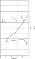
- Fig. 1 shows the situation as it happens in a dual clutch transmission without a special energy recovery solution.
- the two sub-transmissions of the dual clutch transmission rotate at different speeds.
- the internal combustion engine VM is coupled to the second partial transmission TG 2 , which rotates at 2000 revolutions / min, which is shown in the figure with the dashed line ins2_spd.
- the first partial transmission TG 1 rotates at a speed of 1000 revolutions / min and is represented by the graph ins1_spd.
- the internal combustion engine VM is switched off and the second clutch 20 of the second partial transmission TG 2 is opened.
- the speed of the internal combustion engine should then drop rapidly, the desired drop in the combustion speed tgt_eng_spd follows that of the dotted line in Fig. 1 .
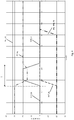
- Figure 2 is a representation of the torques over time on the same scale as Figure 1 .
- the resulting output torque which is available for driving the vehicle, is shown with the top horizontal line out_tq. Since the solution shown is a solution in a double clutch transmission with an electrical machine, the graph also shows the torque curve of the electrical machine EM_tq. Their torque EM_tq is reduced from 30 Nm to 20 Nm at 0.5 seconds when the internal combustion engine VM is switched off. From 0.5 seconds there is no drag torque from the combustion engine on the output, as the clutch opens. In order to maintain the same output torque, less torque of the electrical machine EM is therefore required (30 Nm -> 20 Nm).
- the torque of the first sub-transmission runs along the zero line with ins1_tq, while the second sub-transmission initially still has a torque ins2_tq and is connected in terms of drive technology.
- the torque of the internal combustion engine follows the dashed line eng_drag_tq, which shows that the internal combustion engine continues to spin and continues to run for up to 1.7 seconds even after the combustion process has been stopped for 0.5 seconds.
- the two sub-transmissions are again rotating at different rotational speeds.
- the first sub-transmission TG 1 rotates at 2000 revolutions / min ins1_spd
- the second sub-transmission TG 2 rotates at 1000 revolutions / min, ins2_spd.
- the drop in the rotational speed of the internal combustion engine again follows the graph eng_spd after the internal combustion engine VM has been switched off at 0.5 s. As long as the internal combustion engine VM has a higher speed than the first partial transmission TG 1 at the exemplary 1000 revolutions, energy can be obtained.
- the second clutch 20 of the second partial transmission TG 2 is opened. The goal is to brake the internal combustion engine faster and recover the energy.
- the first clutch 30 of the first partial transmission TG 1 is set with a torque ins1_tq of 20 Nm.
- the torque EM_tq of the electrical machine EM is reduced.
- the internal combustion engine VM is braked somewhat more quickly and the energy of rotation contained in it is used in that the electrical machine EM has to deliver less power. or can generate more.
- the torque EM_tq of the electrical machine EM is reduced below the target torque during the time t in which the first sub-transmission provides a torque.
- the removal of the energy can be recognized from the fact that the internal combustion engine coasts down faster, namely only up to a point in time of 1.5 seconds in the graphic representation, i.e. its residual energy is no longer as high.
- the residual energy in a dual clutch transmission with hybridization cannot be completely recovered.
- the speed of the internal combustion engine VM must be higher than the speed of the slower sub-transmission.
- the complete residual energy of the internal combustion engine VM can be recovered after switching off via the starter generator 13 and stored as electrical energy.
- This process for energy recovery is suitable for vehicles equipped with an automatic start-stop system.
- the starter generator can recover the remaining energy of the internal combustion engine VM until it almost comes to a standstill.
- the entire idea of recovering electrical energy when the combustion stops can also be realized when the combustion engine VM is uncoupled from the drive train. As soon as the internal combustion engine VM is decoupled from the drive train in the state of sailing, the energy contained in the deceleration of the rotational speed of the internal combustion engine VM can be recovered.
- gearbox connected is not important. If a starter generator is present, this energy can also be recovered with high yield.
- the method according to the invention is implemented in a software solution which can be contained in the vehicle control, more precisely either in an engine control, a transmission control or a combination of the controls.
- the method according to the invention is shown schematically in the Figures 6 and 7 shown.
- the process begins with the "Start" block, which can be triggered by different processes.
- the start can be initiated by switching off the internal combustion engine VM.
- the start can also be triggered by uncoupling the internal combustion engine VM from the drive train.
- the start of the method can also be triggered by reducing the demand on the internal combustion engine VM.
- step S1 a torque is set with the first clutch 30 of the first partial transmission TG 1 , while the second clutch 20 is opened. At the same time, the torque of the electrical machine is reduced below the setpoint in S2.
- step S3 This state continues during time t, which is shown in step S3. During this time t, which in the example shown is 0.4 seconds, the electrical machine consumes less energy.
- the speed difference between the internal combustion engine VM and the faster rotating shaft of the partial transmission is used up.
- the speed difference between the output shaft of the internal combustion engine and the faster rotating shaft of the partial transmission is used up.
- the method is stopped at this point, the set torque of the first clutch 30 is reset to zero and the torque of the electric machine is reset to the setpoint.
- Figure 7 schematically represents the simplified solution if the energy of the internal combustion engine VM is given directly to a starter generator or to an electrical machine in the transmission that is decoupled from the rest of the transmission when it is switched off or disconnected.
- Such an arrangement can connect the electrical machines on the input side in front of the gearbox, or a connection on the output side to a shaft.
- step S4 the electrical machine that is to function as a generator is connected to the rotating vehicle element and the kinetic energy is thus converted into electrical energy.
- the process is stopped when either the internal combustion engine VM has come to a complete standstill or, in an alternative solution, has reached its target speed - it can also be idling instead of standstill - or the energy recovery in the generator no longer continues for reasons of efficiency.
- the method can be applied to different hybrid arrangements. It is also an arrangement of the electrical machine EM on the input side in front of the transmission or an arrangement of the electrical machine EM at the transmission output with a direct connection to the output shaft of the transmission.
Landscapes
- Engineering & Computer Science (AREA)
- Chemical & Material Sciences (AREA)
- Combustion & Propulsion (AREA)
- Transportation (AREA)
- Mechanical Engineering (AREA)
- Automation & Control Theory (AREA)
- Hybrid Electric Vehicles (AREA)
- Control Of Vehicle Engines Or Engines For Specific Uses (AREA)
Claims (7)
- Procédé de récupération de l'énergie cinétique d'un moteur à combustion interne (VM) par la réduction de la vitesse de rotation du moteur à combustion interne (VM) pendant une durée (t) prédéfinie dans un véhicule et conversion de l'énergie cinétique de la rotation du moteur à combustion interne (eng_spd), directement au niveau du moteur à combustion interne ou au niveau d'un arbre en rotation du groupe de propulsion, en énergie électrique par au moins une machine électrique (EM, 13), le moteur à combustion interne (VM) étant débrayé de la chaîne cinématique du véhicule, caractérisé en ce que l'une des machines électriques (EM), dans une boîte de vitesses à double embrayage (14) comprenant une première et une deuxième boîte de vitesses partielle (TG1, TG2), peut être accouplée à une deuxième boîte de vitesses partielle (TG2), la vitesse de rotation du moteur à combustion interne (tgt_eng_spd) pendant la durée (t) prédéfinie étant supérieure ou égale à la vitesse de rotation de la première boîte de vitesses partielle (ins1_spd).
- Procédé de récupération de l'énergie cinétique d'un moteur à combustion interne (VM) selon la revendication 1, caractérisé en ce que le moteur à combustion interne (VM) est arrêté et au moins une partie de l'énergie cinétique du moteur à combustion interne (VM) en course d'inertie est récupérée.
- Procédé de récupération de l'énergie cinétique d'un moteur à combustion interne (VM) selon la revendication 1, caractérisé en ce que le moteur à combustion interne (VM) est débrayé et au moins une partie de l'énergie cinétique du moteur à combustion interne (VM) en course d'inertie est récupérée.
- Procédé de récupération de l'énergie cinétique d'un moteur à combustion interne (VM) selon l'une des revendications précédentes, caractérisé en ce que l'énergie du moteur à combustion interne (VM) en course d'inertie intervient au moyen d'un premier accouplement (30) et des positions d'un couple (ins1_tq) dans la première boîte de vitesses partielle (TG1) et d'une réduction du couple des machines électriques (EM_tq) dans la deuxième boîte de vitesses partielle (TG2).
- Procédé de récupération de l'énergie cinétique d'un moteur à combustion interne (VM) selon l'une des revendications précédentes, caractérisé en ce que le début du procédé (Start) est déclenché par la mise à l'arrêt du moteur à combustion interne (VM) et/ou par le débrayage du moteur à combustion interne (VM) de la chaîne cinématique et/ou par la réduction de la sollicitation du moteur à combustion interne (VM).
- Procédé de récupération de l'énergie cinétique d'un moteur à combustion interne (VM) selon l'une des revendications précédentes, caractérisé en ce que le procédé est arrêté (Stopp) lorsque le moteur à combustion interne (VM) s'est immobilisé ou se retrouve au-dessous d'une vitesse de rotation limite ou le rendement du générateur devient inférieur à un seuil.
- Commande destinée à mettre en œuvre le procédé selon l'une des revendications précédentes, la commande (42) étant une commande de moteur et/ou une commande de boîte de vitesses comprenant un échange de données respectif.
Applications Claiming Priority (1)
| Application Number | Priority Date | Filing Date | Title |
|---|---|---|---|
| DE102018206115.7A DE102018206115A1 (de) | 2018-04-20 | 2018-04-20 | Verfahren zur Rückgewinnung von Energie des Verbrennungsmotors sowie Steuergerät zur Durchführung des Verfahrens |
Publications (2)
| Publication Number | Publication Date |
|---|---|
| EP3556592A1 EP3556592A1 (fr) | 2019-10-23 |
| EP3556592B1 true EP3556592B1 (fr) | 2020-04-08 |
Family
ID=66091936
Family Applications (1)
| Application Number | Title | Priority Date | Filing Date |
|---|---|---|---|
| EP19166781.5A Active EP3556592B1 (fr) | 2018-04-20 | 2019-04-02 | Procédé de récupération d'énergie du moteur à combustion interne ainsi qu'appareil de commande permettant la mise en oeuvre dudit procédé |
Country Status (3)
| Country | Link |
|---|---|
| EP (1) | EP3556592B1 (fr) |
| CN (1) | CN110386133B (fr) |
| DE (1) | DE102018206115A1 (fr) |
Families Citing this family (1)
| Publication number | Priority date | Publication date | Assignee | Title |
|---|---|---|---|---|
| DE102020209452A1 (de) * | 2020-07-27 | 2022-01-27 | Magna Pt B.V. & Co. Kg | Verfahren zum Starten eines Verbrennungsmotors in einem Antriebsstrang mit hybridisiertem Doppelkupplungsgetriebe |
Family Cites Families (10)
| Publication number | Priority date | Publication date | Assignee | Title |
|---|---|---|---|---|
| DE102005015485A1 (de) * | 2005-04-05 | 2006-11-30 | Daimlerchrysler Ag | Antriebsstrang eines Fahrzeuges und Verfahren zur Steuerung eines Antriebsstranges |
| EP1714817A1 (fr) * | 2005-04-19 | 2006-10-25 | Getrag Ford Transmissions GmbH | Système d'entraînement hybride avec deux embrayages |
| DE102007031605A1 (de) * | 2007-07-06 | 2009-01-22 | Dr. Ing. H.C. F. Porsche Aktiengesellschaft | Hybridfahrzeug |
| DE102007055827A1 (de) * | 2007-12-17 | 2009-06-18 | Zf Friedrichshafen Ag | Verfahren und Vorrichtung zum Betrieb eines Hybridantriebes eines Fahrzeuges |
| DE102010022749B4 (de) * | 2009-06-25 | 2017-01-12 | Schaeffler Technologies AG & Co. KG | Verfahren zum Steuern eines Kraftfahrzeugs mit Doppelkupplungsgetriebe |
| DE102010044618B4 (de) | 2010-08-27 | 2013-10-31 | Getrag Getriebe- Und Zahnradfabrik Hermann Hagenmeyer Gmbh & Cie Kg | Verfahren zum Ansteuern eines Hybrid-Antriebsstranges |
| DE102011003080A1 (de) * | 2011-01-19 | 2012-07-19 | Robert Bosch Gmbh | Verfahren und Vorrichtung zum Betreiben einer Antriebsvorrichtung |
| CN202480860U (zh) * | 2012-03-21 | 2012-10-10 | 田丽欣 | 一种车辆势能回收系统 |
| DE102012024213A1 (de) * | 2012-12-11 | 2014-06-12 | Volkswagen Aktiengesellschaft | Verfahren zur Steuerung eines Antriebsstrangs eines Kraftfahrzeuges |
| KR101684542B1 (ko) * | 2015-06-26 | 2016-12-08 | 현대자동차 주식회사 | 하이브리드 차량의 엔진 정지 제어 시스템 및 그 방법 |
-
2018
- 2018-04-20 DE DE102018206115.7A patent/DE102018206115A1/de not_active Withdrawn
-
2019
- 2019-04-02 EP EP19166781.5A patent/EP3556592B1/fr active Active
- 2019-04-19 CN CN201910318179.8A patent/CN110386133B/zh active Active
Non-Patent Citations (1)
| Title |
|---|
| None * |
Also Published As
| Publication number | Publication date |
|---|---|
| CN110386133B (zh) | 2022-09-13 |
| DE102018206115A1 (de) | 2019-10-24 |
| EP3556592A1 (fr) | 2019-10-23 |
| CN110386133A (zh) | 2019-10-29 |
Similar Documents
| Publication | Publication Date | Title |
|---|---|---|
| EP2651681B1 (fr) | Motorisation hybride | |
| EP2708400B1 (fr) | Procédé destiné à la commande d'une chaîne d'entraînement hybride | |
| EP2855226B1 (fr) | Procédé et dispositif de commande d'une machine de travail mobile | |
| EP1554154B1 (fr) | Chaine cinematique pour un vehicule automobile, procede de demarrage d'un moteur a combustion interne et procede de production de courant electrique | |
| DE102011077594B4 (de) | Hybridantrieb | |
| DE112016002143B4 (de) | Neustartsteuerungsvorrichtung für eine verbrennungskraftmaschine | |
| EP1747929B1 (fr) | Unité de propulsion pour véhicule à chenilles | |
| EP2651680B1 (fr) | Dispositif pour une chaîne cinématique d'un véhicule hybride, chaîne cinématique et procédé pour faire fonctionner celle-ci | |
| EP1953059B1 (fr) | Procédé de fonctionnement de la transmission d'un véhicule hybride | |
| DE102011089467A1 (de) | Hybridantrieb eines Kraftfahrzeugs und Verfahren zum Betreiben desselben | |
| DE102007055827A1 (de) | Verfahren und Vorrichtung zum Betrieb eines Hybridantriebes eines Fahrzeuges | |
| DE10241457A1 (de) | Verteilergetriebe für Fahrzeuge sowie Verfahren zur Verteilung einer Antriebskraft auf zwei Fahrzeugachsen | |
| DE102010022395A1 (de) | Verfahren zum Wechseln der Gangschaltstufen bei einem Hybridantriebssystem | |
| DE102009023499A1 (de) | Steuerung eines Hybridantriebssystems | |
| WO2006105929A1 (fr) | Chaine cinematique de vehicule a moteur et procede pour commander une chaine cinematique | |
| DE102006054405B4 (de) | Elektrodynamisches Anfahrelement und Verfahren zum Regeln eines elektrodynamischen Anfahrelements | |
| EP3556592A1 (fr) | Procédé de récupération d'énergie du moteur à combustion interne ainsi qu'appareil de commande permettant la mise en uvre dudit procédé | |
| DE102017216984A1 (de) | Verfahren zur Ansteuerung eines Stufengetriebes und eines Antriebsstranges, sowie Steuereinrichtung und Antriebsstrang | |
| WO2005016681A1 (fr) | Procede de commande d'un systeme de propulsion d'un vehicule hybride | |
| DE102019220191A1 (de) | Verfahren zum Starten eines Verbrennungsmotors in einem Antriebsstrang mit hybridisiertem Doppelkupplungsgetriebe | |
| EP3781425B1 (fr) | Procédé de récupération de l'énergie d'un moteur à combustion pendant une montée de rapport et dispositif de commande pour la mise en oeuvre de ce procédé | |
| WO2018065313A1 (fr) | Procédé de démarrage d'un véhicule automobile | |
| WO2018069439A2 (fr) | Architecture de chaîne cinématique hybride à faibles coûts | |
| DE102020206020A1 (de) | Verfahren zum Ansteuern eines Hybridantriebsstrangs | |
| DE102020204284A1 (de) | Verfahren zum Betrieb eines Hybrid-Antriebsstrangs für ein Kraftfahrzeug |
Legal Events
| Date | Code | Title | Description |
|---|---|---|---|
| PUAI | Public reference made under article 153(3) epc to a published international application that has entered the european phase |
Free format text: ORIGINAL CODE: 0009012 |
|
| STAA | Information on the status of an ep patent application or granted ep patent |
Free format text: STATUS: REQUEST FOR EXAMINATION WAS MADE |
|
| 17P | Request for examination filed |
Effective date: 20190910 |
|
| AK | Designated contracting states |
Kind code of ref document: A1 Designated state(s): AL AT BE BG CH CY CZ DE DK EE ES FI FR GB GR HR HU IE IS IT LI LT LU LV MC MK MT NL NO PL PT RO RS SE SI SK SM TR |
|
| AX | Request for extension of the european patent |
Extension state: BA ME |
|
| GRAP | Despatch of communication of intention to grant a patent |
Free format text: ORIGINAL CODE: EPIDOSNIGR1 |
|
| STAA | Information on the status of an ep patent application or granted ep patent |
Free format text: STATUS: GRANT OF PATENT IS INTENDED |
|
| INTG | Intention to grant announced |
Effective date: 20191216 |
|
| GRAS | Grant fee paid |
Free format text: ORIGINAL CODE: EPIDOSNIGR3 |
|
| GRAA | (expected) grant |
Free format text: ORIGINAL CODE: 0009210 |
|
| STAA | Information on the status of an ep patent application or granted ep patent |
Free format text: STATUS: THE PATENT HAS BEEN GRANTED |
|
| AK | Designated contracting states |
Kind code of ref document: B1 Designated state(s): AL AT BE BG CH CY CZ DE DK EE ES FI FR GB GR HR HU IE IS IT LI LT LU LV MC MK MT NL NO PL PT RO RS SE SI SK SM TR |
|
| REG | Reference to a national code |
Ref country code: CH Ref legal event code: EP Ref country code: AT Ref legal event code: REF Ref document number: 1253905 Country of ref document: AT Kind code of ref document: T Effective date: 20200415 |
|
| REG | Reference to a national code |
Ref country code: DE Ref legal event code: R096 Ref document number: 502019000021 Country of ref document: DE |
|
| REG | Reference to a national code |
Ref country code: IE Ref legal event code: FG4D Free format text: LANGUAGE OF EP DOCUMENT: GERMAN |
|
| REG | Reference to a national code |
Ref country code: NL Ref legal event code: MP Effective date: 20200408 |
|
| REG | Reference to a national code |
Ref country code: LT Ref legal event code: MG4D |
|
| PG25 | Lapsed in a contracting state [announced via postgrant information from national office to epo] |
Ref country code: IS Free format text: LAPSE BECAUSE OF FAILURE TO SUBMIT A TRANSLATION OF THE DESCRIPTION OR TO PAY THE FEE WITHIN THE PRESCRIBED TIME-LIMIT Effective date: 20200808 Ref country code: FI Free format text: LAPSE BECAUSE OF FAILURE TO SUBMIT A TRANSLATION OF THE DESCRIPTION OR TO PAY THE FEE WITHIN THE PRESCRIBED TIME-LIMIT Effective date: 20200408 Ref country code: NL Free format text: LAPSE BECAUSE OF FAILURE TO SUBMIT A TRANSLATION OF THE DESCRIPTION OR TO PAY THE FEE WITHIN THE PRESCRIBED TIME-LIMIT Effective date: 20200408 Ref country code: SE Free format text: LAPSE BECAUSE OF FAILURE TO SUBMIT A TRANSLATION OF THE DESCRIPTION OR TO PAY THE FEE WITHIN THE PRESCRIBED TIME-LIMIT Effective date: 20200408 Ref country code: LT Free format text: LAPSE BECAUSE OF FAILURE TO SUBMIT A TRANSLATION OF THE DESCRIPTION OR TO PAY THE FEE WITHIN THE PRESCRIBED TIME-LIMIT Effective date: 20200408 Ref country code: NO Free format text: LAPSE BECAUSE OF FAILURE TO SUBMIT A TRANSLATION OF THE DESCRIPTION OR TO PAY THE FEE WITHIN THE PRESCRIBED TIME-LIMIT Effective date: 20200708 Ref country code: PT Free format text: LAPSE BECAUSE OF FAILURE TO SUBMIT A TRANSLATION OF THE DESCRIPTION OR TO PAY THE FEE WITHIN THE PRESCRIBED TIME-LIMIT Effective date: 20200817 Ref country code: GR Free format text: LAPSE BECAUSE OF FAILURE TO SUBMIT A TRANSLATION OF THE DESCRIPTION OR TO PAY THE FEE WITHIN THE PRESCRIBED TIME-LIMIT Effective date: 20200709 |
|
| PG25 | Lapsed in a contracting state [announced via postgrant information from national office to epo] |
Ref country code: BG Free format text: LAPSE BECAUSE OF FAILURE TO SUBMIT A TRANSLATION OF THE DESCRIPTION OR TO PAY THE FEE WITHIN THE PRESCRIBED TIME-LIMIT Effective date: 20200708 Ref country code: LV Free format text: LAPSE BECAUSE OF FAILURE TO SUBMIT A TRANSLATION OF THE DESCRIPTION OR TO PAY THE FEE WITHIN THE PRESCRIBED TIME-LIMIT Effective date: 20200408 Ref country code: RS Free format text: LAPSE BECAUSE OF FAILURE TO SUBMIT A TRANSLATION OF THE DESCRIPTION OR TO PAY THE FEE WITHIN THE PRESCRIBED TIME-LIMIT Effective date: 20200408 Ref country code: HR Free format text: LAPSE BECAUSE OF FAILURE TO SUBMIT A TRANSLATION OF THE DESCRIPTION OR TO PAY THE FEE WITHIN THE PRESCRIBED TIME-LIMIT Effective date: 20200408 |
|
| PG25 | Lapsed in a contracting state [announced via postgrant information from national office to epo] |
Ref country code: AL Free format text: LAPSE BECAUSE OF FAILURE TO SUBMIT A TRANSLATION OF THE DESCRIPTION OR TO PAY THE FEE WITHIN THE PRESCRIBED TIME-LIMIT Effective date: 20200408 |
|
| REG | Reference to a national code |
Ref country code: DE Ref legal event code: R097 Ref document number: 502019000021 Country of ref document: DE |
|
| PG25 | Lapsed in a contracting state [announced via postgrant information from national office to epo] |
Ref country code: EE Free format text: LAPSE BECAUSE OF FAILURE TO SUBMIT A TRANSLATION OF THE DESCRIPTION OR TO PAY THE FEE WITHIN THE PRESCRIBED TIME-LIMIT Effective date: 20200408 Ref country code: DK Free format text: LAPSE BECAUSE OF FAILURE TO SUBMIT A TRANSLATION OF THE DESCRIPTION OR TO PAY THE FEE WITHIN THE PRESCRIBED TIME-LIMIT Effective date: 20200408 Ref country code: ES Free format text: LAPSE BECAUSE OF FAILURE TO SUBMIT A TRANSLATION OF THE DESCRIPTION OR TO PAY THE FEE WITHIN THE PRESCRIBED TIME-LIMIT Effective date: 20200408 Ref country code: SM Free format text: LAPSE BECAUSE OF FAILURE TO SUBMIT A TRANSLATION OF THE DESCRIPTION OR TO PAY THE FEE WITHIN THE PRESCRIBED TIME-LIMIT Effective date: 20200408 Ref country code: RO Free format text: LAPSE BECAUSE OF FAILURE TO SUBMIT A TRANSLATION OF THE DESCRIPTION OR TO PAY THE FEE WITHIN THE PRESCRIBED TIME-LIMIT Effective date: 20200408 Ref country code: CZ Free format text: LAPSE BECAUSE OF FAILURE TO SUBMIT A TRANSLATION OF THE DESCRIPTION OR TO PAY THE FEE WITHIN THE PRESCRIBED TIME-LIMIT Effective date: 20200408 |
|
| PLBE | No opposition filed within time limit |
Free format text: ORIGINAL CODE: 0009261 |
|
| STAA | Information on the status of an ep patent application or granted ep patent |
Free format text: STATUS: NO OPPOSITION FILED WITHIN TIME LIMIT |
|
| PG25 | Lapsed in a contracting state [announced via postgrant information from national office to epo] |
Ref country code: PL Free format text: LAPSE BECAUSE OF FAILURE TO SUBMIT A TRANSLATION OF THE DESCRIPTION OR TO PAY THE FEE WITHIN THE PRESCRIBED TIME-LIMIT Effective date: 20200408 Ref country code: SK Free format text: LAPSE BECAUSE OF FAILURE TO SUBMIT A TRANSLATION OF THE DESCRIPTION OR TO PAY THE FEE WITHIN THE PRESCRIBED TIME-LIMIT Effective date: 20200408 |
|
| 26N | No opposition filed |
Effective date: 20210112 |
|
| PG25 | Lapsed in a contracting state [announced via postgrant information from national office to epo] |
Ref country code: MC Free format text: LAPSE BECAUSE OF FAILURE TO SUBMIT A TRANSLATION OF THE DESCRIPTION OR TO PAY THE FEE WITHIN THE PRESCRIBED TIME-LIMIT Effective date: 20200408 |
|
| PG25 | Lapsed in a contracting state [announced via postgrant information from national office to epo] |
Ref country code: LU Free format text: LAPSE BECAUSE OF NON-PAYMENT OF DUE FEES Effective date: 20210402 |
|
| REG | Reference to a national code |
Ref country code: BE Ref legal event code: MM Effective date: 20210430 |
|
| PG25 | Lapsed in a contracting state [announced via postgrant information from national office to epo] |
Ref country code: IE Free format text: LAPSE BECAUSE OF NON-PAYMENT OF DUE FEES Effective date: 20210402 |
|
| PG25 | Lapsed in a contracting state [announced via postgrant information from national office to epo] |
Ref country code: BE Free format text: LAPSE BECAUSE OF NON-PAYMENT OF DUE FEES Effective date: 20210430 |
|
| PGFP | Annual fee paid to national office [announced via postgrant information from national office to epo] |
Ref country code: IT Payment date: 20220430 Year of fee payment: 4 Ref country code: FR Payment date: 20220421 Year of fee payment: 4 |
|
| REG | Reference to a national code |
Ref country code: CH Ref legal event code: PL |
|
| PG25 | Lapsed in a contracting state [announced via postgrant information from national office to epo] |
Ref country code: LI Free format text: LAPSE BECAUSE OF NON-PAYMENT OF DUE FEES Effective date: 20220430 Ref country code: CH Free format text: LAPSE BECAUSE OF NON-PAYMENT OF DUE FEES Effective date: 20220430 |
|
| PG25 | Lapsed in a contracting state [announced via postgrant information from national office to epo] |
Ref country code: CY Free format text: LAPSE BECAUSE OF FAILURE TO SUBMIT A TRANSLATION OF THE DESCRIPTION OR TO PAY THE FEE WITHIN THE PRESCRIBED TIME-LIMIT Effective date: 20200408 |
|
| PG25 | Lapsed in a contracting state [announced via postgrant information from national office to epo] |
Ref country code: HU Free format text: LAPSE BECAUSE OF FAILURE TO SUBMIT A TRANSLATION OF THE DESCRIPTION OR TO PAY THE FEE WITHIN THE PRESCRIBED TIME-LIMIT; INVALID AB INITIO Effective date: 20190402 |
|
| PG25 | Lapsed in a contracting state [announced via postgrant information from national office to epo] |
Ref country code: SI Free format text: LAPSE BECAUSE OF FAILURE TO SUBMIT A TRANSLATION OF THE DESCRIPTION OR TO PAY THE FEE WITHIN THE PRESCRIBED TIME-LIMIT Effective date: 20200408 |
|
| GBPC | Gb: european patent ceased through non-payment of renewal fee |
Effective date: 20230402 |
|
| PG25 | Lapsed in a contracting state [announced via postgrant information from national office to epo] |
Ref country code: GB Free format text: LAPSE BECAUSE OF NON-PAYMENT OF DUE FEES Effective date: 20230402 |
|
| PG25 | Lapsed in a contracting state [announced via postgrant information from national office to epo] |
Ref country code: GB Free format text: LAPSE BECAUSE OF NON-PAYMENT OF DUE FEES Effective date: 20230402 Ref country code: FR Free format text: LAPSE BECAUSE OF NON-PAYMENT OF DUE FEES Effective date: 20230430 |
|
| PG25 | Lapsed in a contracting state [announced via postgrant information from national office to epo] |
Ref country code: MK Free format text: LAPSE BECAUSE OF FAILURE TO SUBMIT A TRANSLATION OF THE DESCRIPTION OR TO PAY THE FEE WITHIN THE PRESCRIBED TIME-LIMIT Effective date: 20200408 Ref country code: IT Free format text: LAPSE BECAUSE OF NON-PAYMENT OF DUE FEES Effective date: 20230402 |
|
| PG25 | Lapsed in a contracting state [announced via postgrant information from national office to epo] |
Ref country code: MT Free format text: LAPSE BECAUSE OF FAILURE TO SUBMIT A TRANSLATION OF THE DESCRIPTION OR TO PAY THE FEE WITHIN THE PRESCRIBED TIME-LIMIT Effective date: 20200408 |
|
| REG | Reference to a national code |
Ref country code: DE Ref legal event code: R082 Ref document number: 502019000021 Country of ref document: DE Representative=s name: EULER, MATTHIAS, DR., DE |
|
| REG | Reference to a national code |
Ref country code: AT Ref legal event code: MM01 Ref document number: 1253905 Country of ref document: AT Kind code of ref document: T Effective date: 20240402 |
|
| PGFP | Annual fee paid to national office [announced via postgrant information from national office to epo] |
Ref country code: DE Payment date: 20250422 Year of fee payment: 7 |
|
| PG25 | Lapsed in a contracting state [announced via postgrant information from national office to epo] |
Ref country code: AT Free format text: LAPSE BECAUSE OF NON-PAYMENT OF DUE FEES Effective date: 20240402 |
|
| REG | Reference to a national code |
Ref country code: DE Ref legal event code: R081 Ref document number: 502019000021 Country of ref document: DE Owner name: MAGNA PT B.V. & CO. KGAA, DE Free format text: FORMER OWNER: MAGNA PT B.V. & CO. KG, 74199 UNTERGRUPPENBACH, DE |
|
| PG25 | Lapsed in a contracting state [announced via postgrant information from national office to epo] |
Ref country code: TR Free format text: LAPSE BECAUSE OF FAILURE TO SUBMIT A TRANSLATION OF THE DESCRIPTION OR TO PAY THE FEE WITHIN THE PRESCRIBED TIME-LIMIT Effective date: 20200408 |
|
| PGFP | Annual fee paid to national office [announced via postgrant information from national office to epo] |
Ref country code: AT Payment date: 20260410 Year of fee payment: 5 |