EP3781346B1 - Innengekühltes ventil mit ventilboden und verfahren zu dessen herstellung - Google Patents
Innengekühltes ventil mit ventilboden und verfahren zu dessen herstellung Download PDFInfo
- Publication number
- EP3781346B1 EP3781346B1 EP18752460.8A EP18752460A EP3781346B1 EP 3781346 B1 EP3781346 B1 EP 3781346B1 EP 18752460 A EP18752460 A EP 18752460A EP 3781346 B1 EP3781346 B1 EP 3781346B1
- Authority
- EP
- European Patent Office
- Prior art keywords
- valve
- base element
- valve base
- cavity
- friction welding
- Prior art date
- Legal status (The legal status is an assumption and is not a legal conclusion. Google has not performed a legal analysis and makes no representation as to the accuracy of the status listed.)
- Active
Links
Images


Classifications
-
- B—PERFORMING OPERATIONS; TRANSPORTING
- B23—MACHINE TOOLS; METAL-WORKING NOT OTHERWISE PROVIDED FOR
- B23K—SOLDERING OR UNSOLDERING; WELDING; CLADDING OR PLATING BY SOLDERING OR WELDING; CUTTING BY APPLYING HEAT LOCALLY, e.g. FLAME CUTTING; WORKING BY LASER BEAM
- B23K20/00—Non-electric welding by applying impact or other pressure, with or without the application of heat, e.g. cladding or plating
- B23K20/12—Non-electric welding by applying impact or other pressure, with or without the application of heat, e.g. cladding or plating the heat being generated by friction; Friction welding
- B23K20/129—Non-electric welding by applying impact or other pressure, with or without the application of heat, e.g. cladding or plating the heat being generated by friction; Friction welding specially adapted for particular articles or work
-
- B—PERFORMING OPERATIONS; TRANSPORTING
- B23—MACHINE TOOLS; METAL-WORKING NOT OTHERWISE PROVIDED FOR
- B23K—SOLDERING OR UNSOLDERING; WELDING; CLADDING OR PLATING BY SOLDERING OR WELDING; CUTTING BY APPLYING HEAT LOCALLY, e.g. FLAME CUTTING; WORKING BY LASER BEAM
- B23K20/00—Non-electric welding by applying impact or other pressure, with or without the application of heat, e.g. cladding or plating
- B23K20/12—Non-electric welding by applying impact or other pressure, with or without the application of heat, e.g. cladding or plating the heat being generated by friction; Friction welding
-
- B—PERFORMING OPERATIONS; TRANSPORTING
- B21—MECHANICAL METAL-WORKING WITHOUT ESSENTIALLY REMOVING MATERIAL; PUNCHING METAL
- B21K—MAKING FORGED OR PRESSED METAL PRODUCTS, e.g. HORSE-SHOES, RIVETS, BOLTS OR WHEELS
- B21K1/00—Making machine elements
- B21K1/20—Making machine elements valve parts
-
- F—MECHANICAL ENGINEERING; LIGHTING; HEATING; WEAPONS; BLASTING
- F01—MACHINES OR ENGINES IN GENERAL; ENGINE PLANTS IN GENERAL; STEAM ENGINES
- F01L—CYCLICALLY OPERATING VALVES FOR MACHINES OR ENGINES
- F01L3/00—Lift-valve, i.e. cut-off apparatus with closure members having at least a component of their opening and closing motion perpendicular to the closing faces; Parts or accessories thereof
-
- F—MECHANICAL ENGINEERING; LIGHTING; HEATING; WEAPONS; BLASTING
- F01—MACHINES OR ENGINES IN GENERAL; ENGINE PLANTS IN GENERAL; STEAM ENGINES
- F01L—CYCLICALLY OPERATING VALVES FOR MACHINES OR ENGINES
- F01L3/00—Lift-valve, i.e. cut-off apparatus with closure members having at least a component of their opening and closing motion perpendicular to the closing faces; Parts or accessories thereof
- F01L3/12—Cooling of valves
- F01L3/14—Cooling of valves by means of a liquid or solid coolant, e.g. sodium, in a closed chamber in a valve
-
- F—MECHANICAL ENGINEERING; LIGHTING; HEATING; WEAPONS; BLASTING
- F01—MACHINES OR ENGINES IN GENERAL; ENGINE PLANTS IN GENERAL; STEAM ENGINES
- F01P—COOLING OF MACHINES OR ENGINES IN GENERAL; COOLING OF INTERNAL-COMBUSTION ENGINES
- F01P3/00—Liquid cooling
- F01P3/12—Arrangements for cooling other engine or machine parts
- F01P3/14—Arrangements for cooling other engine or machine parts for cooling intake or exhaust valves
-
- B—PERFORMING OPERATIONS; TRANSPORTING
- B22—CASTING; POWDER METALLURGY
- B22F—WORKING METALLIC POWDER; MANUFACTURE OF ARTICLES FROM METALLIC POWDER; MAKING METALLIC POWDER; APPARATUS OR DEVICES SPECIALLY ADAPTED FOR METALLIC POWDER
- B22F3/00—Manufacture of workpieces or articles from metallic powder characterised by the manner of compacting or sintering; Apparatus specially adapted therefor ; Presses and furnaces
- B22F3/22—Manufacture of workpieces or articles from metallic powder characterised by the manner of compacting or sintering; Apparatus specially adapted therefor ; Presses and furnaces for producing castings from a slip
- B22F3/225—Manufacture of workpieces or articles from metallic powder characterised by the manner of compacting or sintering; Apparatus specially adapted therefor ; Presses and furnaces for producing castings from a slip by injection molding
-
- F—MECHANICAL ENGINEERING; LIGHTING; HEATING; WEAPONS; BLASTING
- F01—MACHINES OR ENGINES IN GENERAL; ENGINE PLANTS IN GENERAL; STEAM ENGINES
- F01L—CYCLICALLY OPERATING VALVES FOR MACHINES OR ENGINES
- F01L2303/00—Manufacturing of components used in valve arrangements
Definitions
- the present invention relates to an internally cooled valve with a valve base inserted by friction welding.
- DE 102015220891 A1 , US 2006/0005792 A1 (Base for the preamble of claim 1) and DE 102015116009 B3 (Base for the preamble of claim 7) each disclose cavity valves, the production of which involves friction welding a valve base with a valve head in order to close the cavity of the valve.
- the present invention relates to a method for producing an internally cooled valve, the valve base of which has been connected to the valve head by friction welding, and to a valve produced by this method. Preferred embodiments are described in the dependent claims.
- a method of manufacturing an internally cooled valve according to claim 1 is provided.
- a friction welding process can enable a high material density and a uniform structure or a relatively uniform structure transition.
- One aspect of friction welding concerns the transmission of the torque required for friction welding, which is very unfavorable in the present case because the valve stem on which the valve can be clamped is much thinner than the diameter of the resulting friction weld seam. There may therefore be a risk of twisting the valve plate off the valve stem during friction welding. This must be taken into account when designing the friction welding parameters.
- contact between the friction partners can also be optimized in order to achieve welding in both the axial direction and the radial direction.
- the valve base element to be welded should not only be welded in an axial direction, but also in a radial direction, for which there is much less experience compared to pure friction welding in the axial direction.
- the friction welding is carried out as inductive friction welding.
- This design allows friction welding to be carried out with a lower torque, which can in particular allow the valve body to be clamped to the valve stem when welding to the valve base element, without the valve stem being sheared off by torsional forces.
- Another exemplary embodiment of the method further includes filling the cavity at least partially with a coolant such as sodium or a coolant comprising sodium before closing the cavity by friction welding.
- a coolant such as sodium or a coolant comprising sodium
- the valve does not have to be opened, filled and closed again after the opening at the bottom of the valve plate has been closed.
- the sodium should be filled into the valve stem and preferably the valve stem should be clamped using a cooled chuck or a cooled collet.
- the valve base element and/or the valve body has an engagement structure.
- the engagement structure clamps the valve base element and/or the valve body in a centered manner.
- the engagement structure can be designed in such a way that it enables increased torque transmission to the valve base element and/or the valve body.
- a central bore is provided on the valve base element.
- the valve base element can also be provided with a flank toothing, which can be brought into engagement with a corresponding toothing on a drive element in order to be able to transmit the torque during friction welding.
- the toothing runs in the circumferential direction and the amplitude of the toothing runs in the axial direction.
- the flank teeth can be designed as zigzag or sawtooth teeth in order to be able to transmit large torques. It is also possible to design the engagement structure as a 3-, 4-, 5- or 6-corner prism in order to be able to clamp the engagement structure in a jaw chuck.
- the back of the valve disk can be provided with an engagement or driver structure which allows a higher torque to be transmitted to the valve disk than would be possible with the shaft alone. Introducing force at the edge of the valve plate also appears to be problematic, since only a relatively small amount of torque can be transmitted due to the small axial width of the valve plate edge.
- the engagement structures on the back of the valve plate and/or the valve base element can make friction welding possible here.
- this further includes removing and/or removing the engagement structure.
- This can be achieved by grinding, milling or other cutting or non-cutting processes.
- at least part of the intervention structure is removed.
- a part of the engagement structure can remain on the valve plate and serve, for example, as cooling fins.
- Another exemplary embodiment of the method uses a valve base element and a valve body with a welding surface contour which, during a friction welding process, produces welding in the cavity in the form of a (circumferential) cooling fin.
- welding usually occurs and emerges from the side of a welding gap. Since it is to be expected that welding will also occur on the side of the cavity, the welding contour and the other friction welding parameters can be selected so that the welding, which extends into the cavity, has the shape of a circumferential cooling fin in order to prevent heat transfer from the Valve base or the edge of the valve plate towards the coolant improve.
- Friction welding parameters influence the shape of the resulting welding.
- this further includes removing or removing an external welding flash. Welding on the outside of the valve or on the outside of the valve base can be removed after friction welding. It is also planned to remove an external friction welding extrusion using machining or non-machining after friction welding.
- the method according to the invention further comprises producing a valve base element by sintering from a valve base element green part or brown part.
- a new technique is used to produce the valve base element. Through the use of sintered materials, it has become easier to produce cooling fins or another structure, for example to influence coolant flow in the cavity. All design and layout parameters can be easily implemented during sintering, since when a green or brown part is produced, the material does not yet have the high strength that is required for later use or operation.
- valve base element green part or brown part is produced by metal powder injection molding. These processes allow quick and easy production of valve base element green parts or brown parts without the need for significant machining effort.
- a valve base element with a coolant or coolant guide structure and an engagement structure can be produced quickly and efficiently, without the forming steps and machining usually required for this being necessary.
- a valve base element green part is further provided for a valve base element green part to be freed from a binder by thermal or chemical debinding and to be transformed into a brown part before the brown part is sintered into the final valve base element. It is also possible to view thermal debinding as a sintering process step, whereby the green part is heated so that thermal debinding takes place before actual sintering.
- an internally cooled valve according to claim 7 is provided.
- this has a friction welding projection on an inside of the cavity, which has the shape of a cooling fin.
- the cooling fin in the valve head allows improved heat transfer from the valve head to the coolant.
- the cooling fin or the two cooling fins that can occur during a friction welding process extend from a previous welding gap into the cavity.
- the valve base element is provided with a cooling fin and/or flow influencing structure on a surface facing the cavity.
- the inner surface of the valve base element can be provided with a structure that can improve improved cooling or improved heat transfer to the coolant even outside of a cooling fin generated by welding.
- a flow guide structure such as a jet guide cone or a jet diversion screw can also be attached to the valve base element in order to distribute coolant flowing from the valve stem into the cavity in the valve head.
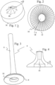
- Figure 1 shows a perspective view of a valve base element 12.
- a later inside 20 of the valve base element 12 and a cooling fin / flow influencing structure 14 shown, which is intended to distribute coolant flowing from above from a hollow valve stem evenly in the valve head.
- an engagement structure 16 or torque transmission element can be seen, with which torque can be transmitted to the valve base element 12 during a friction welding process.
- a sawtooth profile can also be used to enable even better torque transmission even with low axial contact or friction welding pressures.
- Figure 2 shows the valve base element 12 from Figure 1 in a lower view, whereby the engagement structure 18 or the torque transmission element can be seen as flank teeth.
- a hole is arranged as a centering element 18 on an underside of the valve base element 12.
- Figures 3 and 4 represent a perspective view and a section view of one
- the valve bodies 4 each include a valve stem 6 and a valve plate 8. From the side of the valve plate 8, a cavity 10 opens for a coolant such as sodium or a material that is liquid at operating temperature and contains sodium. Through the opening on the valve base, a structurally stable valve can be produced very easily on the one hand, and on the other hand, a cavity can be produced very easily in the valve body, which extends over a large area of the diameter of the valve head 8.
- a coolant such as sodium or a material that is liquid at operating temperature and contains sodium.
- FIGs 5 and 6 show a beginning and an end of a friction welding process according to the invention.
- the valve base element 12 with the cooling fin/flow influencing structure 14 is attached to the cavity 10 of the valve body 4 facing the latter.
- the valve base element 12 is clamped or placed on a friction welding mandrel 26, while the valve body 4 itself is clamped on the valve stem 6.
- the friction welding mandrel 26 is rotated, as a result of which the contact surface between the valve base element 12 and the valve body 4 is heated by frictional heat. This can also be further heated using additional induction heating.
- FIG. 6 represents one end of a friction welding process according to the invention.
- the valve base element 12 was pressed into the valve body 4 after the respective metals had heated up sufficiently to achieve sufficient deformability. For the sake of clarity, friction welding is not shown here.
- Figure 7 shows a partial sectional view through the head of a valve 2 according to the invention.
- a protruding remainder of the valve base element 12 was removed by a machining process, so that a substantially flat valve base was achieved.
- the valve base element 12 is connected to the valve body 4 or the valve head 8 via the welding area or the heat-affected zone 22. Friction welding that had occurred on the outside was also removed.
- a friction welding projection extends on an inside 20 or in the cavity 10.
- the friction welding output 24 could be produced in the form of a cooling fin. This can also improve the heat transfer from the valve head 8 to a coolant located in the cavity 10 (but not shown).
- FIG 8 shows a partial perspective view of a valve 2 according to the invention.
- the valve stem 6 ends in the valve head 8.
- the opening of the cavity Figure 3 is closed by the valve base element 12.
- the engagement elements of the valve base element 12 Figure 2 were removed. Only part of the bore of the centering element 18 can still be seen on the bottom of the valve head.
- the welding area/heat affected zone is indicated by dashed lines.
- Figure 9 represents a valve base element 12, which is placed on a friction welding mandrel 24.
- the friction welding mandrel 26 is provided with structures that are complementary to the engagement element 16 of the valve base element 12 for transmitting a torque and complementary to the centering element 18 of the valve base element 12.
- the shape of the engagement/centering element determines how and how much torque can be transmitted and whether the valve base element 12 should or must be further clamped. Contrary to the illustration, a sawtooth-shaped flank toothing is preferred in order to be able to transmit the torque from the friction welding mandrel 26 to the valve base element 12 independently of an axial force component.
Landscapes
- Engineering & Computer Science (AREA)
- Mechanical Engineering (AREA)
- General Engineering & Computer Science (AREA)
- Chemical & Material Sciences (AREA)
- Combustion & Propulsion (AREA)
- Pressure Welding/Diffusion-Bonding (AREA)
Description
- Die vorliegende Erfindung betrifft ein innengekühltes Ventil mit einem durch Reibschweißen eingesetzten Ventilboden.
- Bisher werden verschiedene Methoden verwendet, um hohle innengekühlte Ventile für Verbrennungsmotoren herzustellen. Es ist bekannt, einen Ventilschaft durch Reibschweißen zu verschließen. Es ist ebenfalls bekannt, einen Ventilboden einzusetzen, um einen Hohlraum in einem innengekühlten Ventil zu verschließen. Herkömmlicherweise wird bei einem gebauten Ventil der Ventilboden durch Elektronenstrahl- oder Laserschweißen mit dem Ventilkopf verbunden. Es gibt jedoch auch andere Möglichkeiten, einen Hohlraum in einem Innengekühlten Ventil zu verschließen, beispielsweise durch ein Verschließen einer Bohrung in einem Ventilschaft.
DE 102015220891 A1 ,US 2006/0005792 A1 (Basis für den Oberbegriff des Anspruchs 1) undDE 102015116009 B3 (Basis für den Oberbegriff des Anspruchs 7) offenbaren jeweils Hohlraumventile, deren Herstellung ein Reibschweißen eines Ventilbodens mit einem Ventilkopf umfasst, um den Hohlraum des Ventils zu verschließen. - Es ist erstrebenswert, ein Verfahren zur Verfügung zu haben, mit dem sich innengekühlte Ventile insbesondere mit einem hohlen Ventilkopf, sogenannte Hohlkopfventile einfach und kostengünstig herstellen lassen.
- Die vorliegende Erfindung betrifft Verfahren zur Herstellung eines innengekühlten Ventils, dessen Ventilboden durch Reibschweißen mit dem Ventilkopf verbunden wurde, sowie ein durch dieses Verfahren hergestelltes Ventil. Bevorzugte Ausführungen sind in den abhängigen Ansprüchen beschrieben.
- Gemäß einem ersten Aspekt der vorliegenden Erfindung wird ein Verfahren zum Herstellen eines innengekühlten Ventils gemäß des Anspruchs 1 bereitgestellt.
- Bisherige Verbindungsverfahren wie Elektronenstrahlschweißen, Laserschweißen oder dergleichen weisen deutliche Nachteile bezüglich der fertigen Materialeigenschaften auf. Ein Reibschweißvorgang hingegen kann eine hohe Materialdichte und ein gleichmäßiges Gefüge bzw. einen relativ gleichmäßigen Gefüge-Übergang ermöglichen.
- Ein Aspekt beim Reibschweißen betrifft eine Übertragung des zum Reibschweißen notwendigen Drehmoments, was bei dem vorliegenden Fall sehr ungünstig ausfällt, da der Ventilschaft, an dem das Ventil eingespannt werden kann, viel dünner ist als der Durchmesser der resultierenden Reibschweißnaht. Es kann also eine Gefahr bestehen, den Ventilteller beim Reibschweißen von dem Ventilschaft abzudrehen. Dies ist bei einer Auslegung der Reibschweißparamter zu beachten.
- Um die Verfahrensparameter des Verfahrens zu optimieren, kann zudem ein Kontakt der Reibpartner optimiert werden, um sowohl eine Verschweißung in Axialrichtung als auch in Radialrichtung zu erreichen. Das zu verschweißende Ventilbodenelement soll hier nicht nur in einer axialen Richtung, sondern auch in einer Radialrichtung verschweißt werden, wofür im Vergleich zu einer reinen Reibverschweißung in Axialrichtung viel weniger Erfahrungswerte vorliegen.
- Bei einer beispielhaften Ausführungsform des Verfahrens wird das Reibschweißen als induktives Reibschweißen ausgeführt. Diese Ausführung gestattet es, das Reibschweißen mit einem geringeren Drehmoment auszuführen, was es insbesondere gestatten kann, den Ventilköper beim Verschweißen mit dem Ventilbodenelement am Ventilschaft einzuspannen, ohne dass der Ventilschaft durch Torsionskräfte abgeschert wird.
- Eine weitere beispielhafte Ausführungsform des Verfahrens umfasst weiter, dass der Hohlraum zumindest teilweise mit einem Kühlmittel wie Natrium oder einem Kühlmittel, das Natrium umfasst, gefüllt wird, bevor der Hohlraum durch Reibschweißen verschlossen wird. Somit muss das Ventil nach dem Verschließen der Öffnung unten am Ventilteller nicht noch einmal geöffnet, gefüllt und verschlossen werden. Dazu sollte das Natrium in den Ventilschaft gefüllt werden und vorzugsweise der Ventilschaft durch ein gekühltes Futter oder eine gekühlte Spannzange eingespannt werden.
- Bei dem erfindungsgemässen Verfahren weist das Ventilbodenelement und/oder der Ventilkörper eine Eingriffsstruktur auf. Durch die Eingriffsstruktur wird das Ventilbodenelement und/oder der Ventilkörper zentriert eingespannt. Weiterhin kann die Eingriffsstruktur so gestaltet sein, dass sie eine erhöhte Drehmomentübertragung auf das Ventilbodenelement und/oder den Ventilkörper ermöglicht. Hier ist insbesondere eine Zentralbohrung an dem Ventilbodenelement vorgesehen. Das Ventilbodenelement kann zudem mit einer Flankenverzahnung versehen sein, die mit einer entsprechenden Verzahnung an einem Antriebselement in Eingriff gebracht werden kann, um das Drehmoment beim Reibschweißen übertragen zu können. Die Verzahnung verläuft dabei in Umfangsrichtung und die Amplitude der Verzahnung verläuft in Axialrichtung. Die Flankenverzahnung kann als Zickzack- oder als Sägezahnverzahnung ausgeführt sein, um große Drehmomente übertragen zu können. Es ist ebenfalls möglich, die Eingriffsstruktur als ein 3-, 4-, 5- oder 6-Eck-Prisma auszuführen, um die Eingriffsstruktur in einem Backenfutter einspannen zu können. Weiterhin kann die Rückseite des Ventiltellers mit einer Eingriffs- oder Mitnehmerstruktur versehen sein, die es gestattet, ein höheres Drehmoment auf den Ventilteller zu übertragen als es mit dem Schaft alleine möglich wäre. Auch eine Krafteinleitung am Rand des Ventiltellers erscheint problematisch, da durch die geringe axiale Breite des Ventiltellerrandes ebenfalls nur ein relativ geringes Drehmoment übertragen werden kann. Die Eingriffsstrukturen an der Ventilteller-Rückseite und/oder dem Ventilbodenelement kann hier ein Reibschweißen erst ermöglichen.
- Bei einer anderen beispielhaften Ausführungsform des Verfahrens umfasst dieses weiter ein Entfernen und/oder Abtragen der Eingriffsstruktur. Dies kann durch Schleifen, Fräsen oder andere spanende oder auch nichtspanende Verfahren erreicht werden. Hier wird zumindest ein Teil der Eingriffsstruktur abgetragen. Ein Teil der Eingriffsstruktur kann an dem Ventilteller verbleiben und beispielsweise als Kühlrippen dienen.
- Eine andere beispielhafte Ausführungsform des Verfahrens verwendet ein Ventilbodenelement und einen Ventilkörper mit einer Schweißflächenkontur, die bei einem Reibschweißvorgang einen Schweißaustrieb in dem Hohlraum in einer Form einer (umlaufenden) Kühlrippe erzeugt. Beim Reibschweißen tritt üblicherweise ein Schweißaustrieb auf, der seitlich aus einem Schweißspalt austritt. Da zu erwarten ist, dass auch auf der Seite des Hohlraums ein Schweißaustritt auftritt, können die Schweißkontur und die anderen Reibschweißparameter so gewählt werden, dass der Schweißaustritt, der sich in den Hohlraum erstreckt, die Form einer umlaufenden Kühlrippe aufweist, um einen Wärmeübertrag von dem Ventilboden bzw. dem Rand des Ventiltellers auf das Kühlmittel zu verbessern. Hier kann durch die Form der jeweiligen Schweißflächenkonturen und der
- Reibschweißparameter die Form des entstehenden Schweißaustriebs beeinflusst werden. Bei einer weiteren Ausführungsform des Verfahrens umfasst dieses weiter ein Abtragen bzw. Entfernen eines äußeren Schweißaustriebs. Ein Schweißaustrieb an einer Außenseite des Ventils bzw. außen am Ventilboden kann nach dem Reibschweißen abgetragen werden. Es ist zudem vorgesehen, einen äußeren Reibschweißaustrieb nach dem Reibschweißen spanend oder nichtspanend abzutragen.
- Das erfindungsgemässe Verfahren umfasst weiter ein Herstellen eines Ventilbodenelements durch Sintern aus einem Ventilbodenelement-Grünteil oder -Braunteil. Dabei wird eine neue Technik angewendet, das Ventilbodenelement herzustellen. Durch die Nutzung von Sintermaterialien ist es einfacher geworden, Kühlrippen oder eine andere Struktur herzustellen, um beispielsweise einen Kühlmittelfluss in dem Hohlraum zu beeinflussen. Alle Design- und Auslegungsparameter lassen sich beim Sintern leicht umsetzen, da das Material bei einer Herstellung eines Grün- oder Braunteils noch nicht die hohe Festigkeit aufweist, die bei einem späteren Einsatz bzw. Betrieb benötigt wird.
- Bei dem erfindungsgemässen Verfahren wird das Ventilbodenelement-Grünteil oder -Braunteil durch Metallpulver-Spritzgießen hergestellt. Diese Verfahren gestatten eine schnelle und einfache Herstellung von Ventilbodenelement-Grünteilen oder -Braunteilen, ohne dass dafür ein erheblicher Aufwand an spanender Bearbeitung notwendig ist. Hier kann erstmals ein Ventilbodenelement mit eine Kühl- bzw Kühlflüssigkeits-Leitstruktur und einer Eingriffsstruktur schnell und effizient hergestellt werden, ohne dass die dafür üblicherweise benötigten Umformschritte und spanende Bearbeitung notwendig wären. Es ist weiter vorgesehen, ein Ventilbodenelement-Grünteil durch thermisches oder chemisches Entbindern von einem Binder zu befreien und in ein Braunteil zu verwandeln, bevor das Braunteil durch Sintern zu dem endgültigen Ventilbodenelement gesintert wird. Es ist ebenfalls möglich, das thermische Entbinden als einen Verfahrensschritt des Sinters zu betrachten, wobei das Grünteil so erhitzt wird, dass vor einem eigentlichen Sintern ein thermisches Entbindern stattfindet.
- Gemäß einem weiteren Aspekt der vorliegenden Erfindung wird ein innengekühltes Ventil gemäß dem Anspruch 7 bereitgestellt.
- Bei einer Ausführungsform des innengekühlten Ventils, weist dieses einen Reibschweißaustrieb an einer Innenseite des Hohlraums auf, der eine Form einer Kühlrippe zeigt. Die Kühlrippe in dem Ventilkopf gestattet einen verbesserten Wärmeübertrag von dem Ventilkopf auf das Kühlmittel. Die Kühlrippe bzw. die zwei Kühlrippen, die bei einem Reibschweißvorgang auftreten können, erstrecken sich von einem vorhergehenden Schweißspalt bis in den Hohlraum.
- Bei dem erfindungsgemässen innengekühlten Ventil ist das Ventilbodenelement auf einer dem Hohlraum zugewandten Fläche mit einer Kühlrippen- und/oder Strömungsbeeinflussungsstruktur versehen. Die Innenfläche des Ventilbodenelements kann dabei mit einer Struktur versehen sein, die eine verbesserte Kühlung bzw. einen verbesserten Wärmeübertrag auf das Kühlmittel auch außerhalb einer durch einen Schweißaustrieb erzeugten Kühlrippe verbessern kann. Zusätzlich oder anstelle von Kühlrippen kann auch eine Strömungsleit-Struktur wie ein Strahlleiter-Kegel oder eine Strahl-Umleitungsschnecke an dem Ventilbodenelement angebracht sein, um ein aus dem Ventilschaft strömendes Kühlmittel in dem Hohlraum in dem Ventilkopf zu verteilen.
- Im Folgenden wird die Erfindung anhand von schematischen Figuren näher veranschaulicht.
-
Figuren 1 und 2 zeigen eine perspektivische Ansicht eines Ventilbodenelements. -
Figuren 3 und 4 stellen eine perspektivische Ansicht und eine Schnittansicht eines Ventilkörpers dar. -
Figuren 5 und 6 zeigen einen Beginn und ein Ende eines erfindungsgemäßen Reibschweißvorgangs. -
Figuren 7 und 8 stellen eine Schnitt-Teilansicht und eine perspektivische Teilansicht eines erfindungsgemäßen Ventils dar. -
Figur 9 stellt ein Ventilbodenelement dar, das auf einen Reibschweißdorn aufgesetzt ist. - Sowohl in der Beschreibung als auch in den Figuren werden gleiche oder ähnliche Bezugszeichen verwendet, um auf gleiche oder ähnliche Elemente oder Komponenten Bezug zu nehmen.
-
Figur 1 zeigt eine perspektivische Ansicht eines Ventilbodenelements 12. In der Ansicht vonFigur 1 ist eine spätere Innenseite 20 des Ventilbodenelements 12 und eine Kühlrippen- / Strömungsbeeinflussungsstruktur 14 dargestellt, die ein von oben aus einem hohlen Ventilschaft strömendes Kühlmittel gleichmäßig in dem Ventilkopf verteilen soll. Unten am dem Ventilbodenelement 12 ist eine Eingriffsstruktur 16 bzw. Drehmoment-Übertragungselement zu erkennen, mit der während eines Reibschweißvorgangs ein Drehmoment auf das Ventilbodenelement 12 übertragen werden kann. Abweichend von der Darstellung kann auch ein Sägezahnprofil verwendet werden, um eine noch bessere Drehmomentübertragung auch bei geringen axialen Anpress- bzw. Reibschweißdrücken zu ermöglichen. -
Figur 2 zeigt das Ventilbodenelement 12 vonFigur 1 in einer unteren Ansicht, wobei hier die Eingriffsstruktur 18 bzw. das Drehmoment-Übertragungselement als Flankenzahnung zu erkennen ist. In der Mitte ist eine Bohrung als Zentrierelement 18 auf einer Unterseite des Ventilbodenelements 12 angeordnet. -
Figuren 3 und 4 stellen eine perspektivische Ansicht und eine Schnittansicht eines - Ventilkörpers dar. Die Ventilkörper 4 umfassen jeweils einen Ventilschaft 6 und einen Ventilteller 8. Von der Seite des Ventiltellers 8 aus öffnet sich ein Hohlraum 10 für ein Kühlmittel wie Natrium oder ein bei Betriebstemperatur flüssiges Material, das Natrium enthält. Durch die Öffnung am Ventilboden kann sehr einfach einerseits ein strukturell stabiles Ventil hergestellt werden, und andererseits kann sehr einfach ein Hohlraum in dem Ventilkörper hergestellt werden, der sich über einen großen Bereich eines Durchmessers des Ventilkopfes 8 erstreckt.
-
Figuren 5 und 6 zeigen einen Beginn und ein Ende eines erfindungsgemäßen Reibschweißvorgangs. InFigur 5 ist das Ventilbodenelement 12 mit der Kühlrippen- / Strömungsbeeinflussungsstruktur 14 zum Hohlraum 10 des Ventilkörpers 4 weisend an diesem angesetzt. Das Ventilbodenelement 12 ist auf einem Reibschweißdorn 26 aufgespannt oder aufgesetzt, während der Ventilkörper 4 selbst am Ventilschaft 6 eingespannt ist. Zu Beginn des Verfahrens wird der Reibschweißdorn 26 in eine Drehung versetzt, wodurch sich die Berührungsfläche zwischen Ventilbodenelement 12 und Ventilkörper 4 durch Reibungswärme erwärmt. Dies kann ebenfalls durch eine zusätzliche Induktionsheizung weiter erwärmt werden. -
Figur 6 stellt ein Ende eines erfindungsgemäßen Reibschweißvorgangs dar. Das Ventilbodenelement 12 wurde in den Ventilkörper 4 hineingedrückt, nachdem sich die jeweiligen Metalle hinreichend erwärmt haben, um eine ausreichende Verformbarkeit zu erreichen. Ein Reibschweißaustrieb ist hier der Klarheit halber nicht dargestellt. -
Figur 7 stellt eine Schnitt-Teilansicht durch den Kopf eines erfindungsgemäßen Ventils 2 dar. Ein überstehender Rest des Ventilbodenelements 12 wurde durch einen spanenden Vorgang abgetragen, sodass ein im Wesentlichen ebener Ventilboden erreicht wurde. Das Ventilbodenelement 12 ist über den Schweißbereich bzw. die Wärmebeeinflussungszone 22 mit dem Ventilköper 4 bzw. dem Ventilkopf 8 verbunden. Ein an einer Außenseite aufgetretener Reibschweißaustrieb wurde ebenfalls abgetragen. An einer Innenseite 20 bzw. in dem Hohlraum 10 erstreckt sich ein Reibschweißaustrieb. Durch geeignete Verfahrensparameter sowie eine geeignete Materialwahl konnte der Reibschweißaustrieb 24 in Form einer Kühlrippe erzeugt werden. Dies kann ebenfalls den Wärmeübertrag von dem Ventilkopf 8 auf ein in dem Hohlraum 10 befindliches (jedoch nicht dargestelltes) Kühlmittel verbessern. -
Figur 8 zeigt eine perspektivische Teilansicht eines erfindungsgemäßen Ventils 2. Der Ventilschaft 6 läuft dabei in dem Ventilkopf 8 aus. Die Öffnung des Hohlraumes ausFigur 3 ist durch das Ventilbodenelement 12 verschlossen. Die Eingriffselemente des Ventilbodenelements 12 ausFigur 2 wurden abgetragen. Lediglich ein Teil der Bohrung des Zentrierelements 18 ist noch am Boden des Ventilkopfes zu erkennen. Der Schweißbereich / die Wärmebeeinflussungszone ist durch gestrichelte Linien angedeutet. -
Figur 9 stellt ein Ventilbodenelement 12 dar, das auf einem Reibschweißdorn 24 aufgesetzt ist. Der Reibschweißdorn 26 ist mit Strukturen versehen, die komplementär zu dem Eingriffselement 16 des Ventilbodenelements 12 zur Übertragung eines Drehmoments und komplementär zu dem Zentrierelement 18 des Ventilbodenelements 12 sind. Die Form des Eingriffs-/Zentrierelements entscheidet darüber, wie und wieviel Drehmoment übertragen werden kann, und ob das Ventilbodenelement 12 weiter eingespannt werden soll oder muss. Es wird entgegen der Darstellung eine sägezahnförmige Flankenverzahnung bevorzugt, um das Drehmoment unabhängig von einer axialen Kraftkomponente von dem Reibschweißdorn 26 auf das Ventilbodenelement 12 übertragen zu können. -
- 2
- Innengekühltes Ventil mit Reibverschweißter Bodenelement
- 4
- Rohling / Ventilkörper eines innengekühlten V4ntils
- 6
- Ventilschaft eines innengekühlten Ventils
- 8
- Ventilkopf eines innengekühlten Ventils
- 10
- Hohlraum eines innengekühlten Ventils
- 12
- Ventilbodenelement
- 14
- Kühlrippen- / Strömungsbeeinflussungsstruktur
- 16
- Eingriffsstruktur des Ventilbodenelements
- 18
- Zentrierelement des Ventilbodenelements
- 20
- Innenseite des Ventilbodenelements
- 22
- Schweißbereich / Wärmebeeinflussungszone
- 24
- Reibschweißaustrieb an einer Innenseite des Hohlraums in Form einer Kühlrippe
- 26
- Reibschweißdorn
Claims (8)
- Verfahren zur Herstellung eines innengekühlten Ventils (2) umfassend Bereitstellen eines Ventilkörpers (4) mit einem Ventilschaft (6), der in einem Ventilkopf (8) ausläuft, wobei der Ventilkörper (4) einen Hohlraum (10) aufweist, der zum Ventilkopf (8) hin offen ist,Bereitstellen eines Ventilbodenelements (12), undVerschließen des Hohlraums (10) mit dem Ventilbodenelement (12) durch Reibverschweißen des Ventilbodenelements (12) mit dem Ventilkopf (8),dadurch gekennzeichnet, dassdas Ventilbodenelement (12) und/oder der Ventilkörper (4) eine Eingriffsstruktur (16) aufweist bzw. aufweisen, mit der das Ventilbodenelement (12) und/oder der Ventilkörper (4) zentriert eingespannt wird und ein Drehmoment auf das Ventilbodenelement (12) und/oder den Ventilkörper (4) übertragen wird,wobei das Verfahren umfasstHerstellen eines Ventilbodenelement-Grünteils oder -Braunteils durch Metallpulver-Spritzgießen, und Herstellen des Ventilbodenelements (12) durch Sintern aus dem Ventilbodenelement-Grünteil oder -Braunteil,wobei das Ventilbodenelement (12) auf einer dem Hohlraum (10) zugewandten Fläche mit einer Kühlrippen- und/oder Strömungsbeeinflussungsstruktur (14) versehen wird.
- Verfahren gemäß Anspruch 1, wobei das Reibschweißen als induktives Reibschweißen ausgeführt wird.
- Verfahren gemäß Anspruch 1 oder 2, weiter umfassend zumindest Teilweise füllen des Hohlraums (10) mit einem Kühlmittel wie Natrium oder einem Kühlmittel das Natrium umfasst, bevor der Hohlraum (10) durch Reibschweißen verschlossen wird.
- Verfahren gemäß Anspruch 1, weiter umfassend Entfernen und/oder Abtragen der Eingriffsstruktur (16).
- Verfahren gemäß einem der vorstehenden Ansprüche, wobei das Ventilbodenelement (12) und der Ventilkörper (4) eine Schweißflächenkontur aufweisen, die bei einem Reibschweißvorgang einen Schweißaustrieb (24) in dem Hohlraum (10) in einer gewünschten Form einer Kühlrippe erzeugt.
- Verfahren gemäß Anspruch 5, weiter umfassend Entfernen eines äußeren Schweißaustriebs.
- Innengekühltes Ventil (2) mit einem Ventilkörper (4), der einen Ventilkopf (8) und einen Ventilschaft (6) umfasst, wobei in dem Ventilkörper (4) ein Hohlraum (10) angeordnet ist, der sich bis in den Ventilkopf (8) hinein erstreckt, wobei der Hohlraum (10) durch einen Ventilboden verschlossen ist, der durch Reibschweißen mit dem Ventilkopf (8) verbunden ist, wobei das Ventilbodenelement (12) auf einer dem Hohlraum (10) zugewandten Fläche mit einer Kühlrippen- und/oder Strömungsbeeinflussungsstruktur versehen ist, dadurch gekennzeichnet, dass das Ventilbodenelement (12) und/oder der Ventilkörper (4) eine Eingriffsstruktur (16) aufweist bzw. aufweisen, mit der das Ventilbodenelement (12) und/oder der Ventilkörper (4) zentriert eingespannt werden kann und ein Drehmoment auf das Ventilbodenelement (12) und/oder den Ventilkörper (4) übertragen werden kann, und wobei das Ventilbodenelement (12) durch Sintern aus einem Ventilbodenelement-Grünteil oder -Braunteil hergestellt ist, das durch Metallpulver-Spritzgießen hergestellt ist.
- Innengekühltes Ventil (2) nach Anspruch 7, wobei der Reibschweißaustrieb (24) an einer Innenseite (20) des Hohlraums (10) die Form einer Kühlrippe aufweist, die einen verbesserten Wärmeübertrag von dem Ventilkopf (8) auf das Kühlmittel ermöglicht.
Applications Claiming Priority (2)
| Application Number | Priority Date | Filing Date | Title |
|---|---|---|---|
| DE102017127986.5A DE102017127986A1 (de) | 2017-11-27 | 2017-11-27 | Innengekühltes Ventil mit Ventilboden und Verfahren zu dessen Herstellung |
| PCT/EP2018/071315 WO2019101374A1 (de) | 2017-11-27 | 2018-08-07 | Innengekühltes ventil mit ventilboden und verfahren zu dessen herstellung |
Publications (2)
| Publication Number | Publication Date |
|---|---|
| EP3781346A1 EP3781346A1 (de) | 2021-02-24 |
| EP3781346B1 true EP3781346B1 (de) | 2023-09-27 |
Family
ID=63144994
Family Applications (1)
| Application Number | Title | Priority Date | Filing Date |
|---|---|---|---|
| EP18752460.8A Active EP3781346B1 (de) | 2017-11-27 | 2018-08-07 | Innengekühltes ventil mit ventilboden und verfahren zu dessen herstellung |
Country Status (5)
| Country | Link |
|---|---|
| US (1) | US11311964B2 (de) |
| EP (1) | EP3781346B1 (de) |
| DE (1) | DE102017127986A1 (de) |
| PL (1) | PL3781346T3 (de) |
| WO (1) | WO2019101374A1 (de) |
Families Citing this family (3)
| Publication number | Priority date | Publication date | Assignee | Title |
|---|---|---|---|---|
| DE102022117120A1 (de) * | 2022-07-08 | 2024-01-11 | Federal-Mogul Valvetrain Gmbh | Reibgeschweisstes Hohlraumventil, Komponenten davon und Werkzeug zu dessen Herstellung |
| DE102022117119A1 (de) * | 2022-07-08 | 2024-01-11 | Federal-Mogul Valvetrain Gmbh | Reibgeschweisstes Hohlraumventil, Komponenten davon und Werkzeug zu dessen Herstellung |
| DE102022117117B4 (de) * | 2022-07-08 | 2024-11-07 | Federal-Mogul Valvetrain Gmbh | Ventilrohling und Ventilbodendeckel sowie innengekühltes Hohlventil |
Citations (1)
| Publication number | Priority date | Publication date | Assignee | Title |
|---|---|---|---|---|
| DE2433896A1 (de) * | 1974-07-15 | 1976-02-05 | Volkswagenwerk Ag | Verfahren zum panzern des ventilsitzes eines ventils, insbesondere eines auslassventils eines otto-motors |
Family Cites Families (18)
| Publication number | Priority date | Publication date | Assignee | Title |
|---|---|---|---|---|
| US2136690A (en) * | 1930-08-12 | 1938-11-15 | Eaton Mfg Co | Internal combustion engine valve and seat |
| US2609576A (en) * | 1949-12-06 | 1952-09-09 | Thompson Prod Inc | Method of making hollow shapes |
| US5503122A (en) * | 1992-09-17 | 1996-04-02 | Golden Technologies Company | Engine components including ceramic-metal composites |
| JPH09184404A (ja) * | 1995-12-28 | 1997-07-15 | Fuji Oozx Inc | 内燃機関用中空弁 |
| US5934648A (en) * | 1996-03-13 | 1999-08-10 | The United States Of America As Represented By The Administrator Of The National Aeronautics And Space Administration | Carbon fiber reinforced carbon composite valve for an internal combustion engine |
| US5792402A (en) * | 1996-03-13 | 1998-08-11 | The United States Of America As Represented By The Administrator Of The National Aeronautics And Space Administration | Method of manufacturing carbon fiber reinforced carbon composite valves |
| US6691910B2 (en) * | 2000-12-08 | 2004-02-17 | Fuji Oozx, Inc. | Method of joining different metal materials by friction welding |
| DE10160942A1 (de) * | 2001-12-12 | 2003-06-18 | Daimler Chrysler Ag | Gebautes Ventil für Hubkolbenmaschinen |
| DE10209770A1 (de) | 2002-03-05 | 2003-10-09 | Daimler Chrysler Ag | Leichtbauventil |
| DE10354085B4 (de) * | 2003-11-19 | 2005-11-24 | Daimlerchrysler Ag | Leichtbauventil |
| DE10354086B4 (de) * | 2003-11-19 | 2005-11-24 | Daimlerchrysler Ag | Leichtbauventil |
| US8234788B2 (en) * | 2008-05-13 | 2012-08-07 | GM Global Technology Operations LLC | Method of making titanium-based automotive engine valves |
| KR101542447B1 (ko) * | 2012-10-30 | 2015-08-06 | 니탄 밸브 가부시키가이샤 | 엔진 밸브 |
| JP6316588B2 (ja) * | 2013-12-27 | 2018-04-25 | 日本ピストンリング株式会社 | 内燃機関用バルブとバルブシートの組合せ体 |
| DE102015116010A1 (de) * | 2015-09-22 | 2017-03-23 | Federal-Mogul Valvetrain Gmbh | Gekühltes Ventil für Verbrennungsmotoren mit Entlastungsnut |
| DE102015116009C5 (de) * | 2015-09-22 | 2020-07-30 | Federal-Mogul Valvetrain Gmbh | Ventil für Verbrennungsmotoren mit Leitschaufel für Kühlmittel |
| DE102015220891A1 (de) * | 2015-10-26 | 2017-04-27 | Federal-Mogul Valvetrain Gmbh | Innengekühltes Ventil für Verbrennungsmotoren sowie Verfahren und Vorrichtung zu dessen Herstellung |
| DE102016122514B4 (de) * | 2016-11-22 | 2019-06-27 | Federal-Mogul Valvetrain Gmbh | Feuerverschweißtes innengekühltes Ventil sowie dadurch hergestelltes Ventil |
-
2017
- 2017-11-27 DE DE102017127986.5A patent/DE102017127986A1/de not_active Ceased
-
2018
- 2018-08-07 US US16/767,276 patent/US11311964B2/en active Active
- 2018-08-07 EP EP18752460.8A patent/EP3781346B1/de active Active
- 2018-08-07 PL PL18752460.8T patent/PL3781346T3/pl unknown
- 2018-08-07 WO PCT/EP2018/071315 patent/WO2019101374A1/de not_active Ceased
Patent Citations (1)
| Publication number | Priority date | Publication date | Assignee | Title |
|---|---|---|---|---|
| DE2433896A1 (de) * | 1974-07-15 | 1976-02-05 | Volkswagenwerk Ag | Verfahren zum panzern des ventilsitzes eines ventils, insbesondere eines auslassventils eines otto-motors |
Also Published As
| Publication number | Publication date |
|---|---|
| US20210086292A1 (en) | 2021-03-25 |
| DE102017127986A1 (de) | 2019-05-29 |
| EP3781346A1 (de) | 2021-02-24 |
| WO2019101374A1 (de) | 2019-05-31 |
| PL3781346T3 (pl) | 2024-04-08 |
| US11311964B2 (en) | 2022-04-26 |
Similar Documents
| Publication | Publication Date | Title |
|---|---|---|
| EP2049315B1 (de) | Auswerferstift für eine werkzeugform sowie verfahren zum herstellen eines solchen auswerferstifts | |
| EP2830803B1 (de) | Turbinenläufer für eine abgasturbine sowie ein verfahren zur herstellung des turbinenläufers | |
| WO2012084252A1 (de) | Heisskanaldüse | |
| DE102008049055B4 (de) | Verfahren zur Reparatur eines Gehäuseflanschs eines Flugzeugtriebwerks | |
| DE102020118836B3 (de) | Fertigungsverfahren für ein formgebendes Werkzeugteil eines Formwerkzeugs | |
| EP1042086B2 (de) | Verfahren zur herstellung eines bohrwerkzeugs f?r werkzeugmaschinen | |
| EP3481701B1 (de) | Zahnstange und ein verfahren zur herstellung einer zahnstange für ein lenkgetriebe eines kraftfahrzeugs | |
| WO2019101374A1 (de) | Innengekühltes ventil mit ventilboden und verfahren zu dessen herstellung | |
| EP1485582A1 (de) | Leichtbauventil | |
| DE602006000221T2 (de) | Verfahren zum Kneten von Metallknüppeln und Anordnung eines Mantels und eines Deckels zur Durchführung des Verfahrens | |
| DE3636798C2 (de) | ||
| EP2866968B1 (de) | Verfahren und anordnung zum herstellen eines räumlichen werkstoffverbunds unter verwendung eines expansionskörpers | |
| EP3870814B1 (de) | Innengekühltes ventil mit kühlmittelleitsystem | |
| DE102016122514B4 (de) | Feuerverschweißtes innengekühltes Ventil sowie dadurch hergestelltes Ventil | |
| EP3793762B1 (de) | Verfahren zur herstellung eines geschweissten hohlraumventils | |
| DE202009018136U1 (de) | Werkzeug zum Rührreibschweißen | |
| DE3730011C2 (de) | ||
| DE102016212301A1 (de) | Zahnstange und ein Verfahren zur Herstellung einer Zahnstange für ein Lenkgetriebe eines Kraftfahrzeugs | |
| DE102004042706B3 (de) | Werkzeug zum Thixoschmieden | |
| DE112014006913T5 (de) | Vorrichtung zurn Herstellen eines Metallteils | |
| EP2487007B1 (de) | Verfahren zur Herstellung einer Auswerferhülse für eine Werkzeugform | |
| DE102011109812B4 (de) | Bearbeitungsvorrichtung zur Herstellung einer Bauteilverbindung | |
| AT517240B1 (de) | Barrel für eine Thixomoldingvorrichtung | |
| DE102022117119A1 (de) | Reibgeschweisstes Hohlraumventil, Komponenten davon und Werkzeug zu dessen Herstellung | |
| DE1627778A1 (de) | Verfahren zum herstellen von spiralbohrern oder aehnlichen werkzeugen |
Legal Events
| Date | Code | Title | Description |
|---|---|---|---|
| STAA | Information on the status of an ep patent application or granted ep patent |
Free format text: STATUS: UNKNOWN |
|
| STAA | Information on the status of an ep patent application or granted ep patent |
Free format text: STATUS: THE INTERNATIONAL PUBLICATION HAS BEEN MADE |
|
| PUAI | Public reference made under article 153(3) epc to a published international application that has entered the european phase |
Free format text: ORIGINAL CODE: 0009012 |
|
| STAA | Information on the status of an ep patent application or granted ep patent |
Free format text: STATUS: REQUEST FOR EXAMINATION WAS MADE |
|
| 17P | Request for examination filed |
Effective date: 20200826 |
|
| AK | Designated contracting states |
Kind code of ref document: A1 Designated state(s): AL AT BE BG CH CY CZ DE DK EE ES FI FR GB GR HR HU IE IS IT LI LT LU LV MC MK MT NL NO PL PT RO RS SE SI SK SM TR |
|
| AX | Request for extension of the european patent |
Extension state: BA ME |
|
| DAV | Request for validation of the european patent (deleted) | ||
| DAX | Request for extension of the european patent (deleted) | ||
| REG | Reference to a national code |
Ref country code: DE Ref legal event code: R079 Free format text: PREVIOUS MAIN CLASS: B23K0020120000 Ipc: B21K0001200000 Ref document number: 502018013341 Country of ref document: DE |
|
| RIC1 | Information provided on ipc code assigned before grant |
Ipc: F01L 3/00 20060101ALI20230314BHEP Ipc: F01L 3/14 20060101ALI20230314BHEP Ipc: B23K 20/12 20060101ALI20230314BHEP Ipc: B21K 1/20 20060101AFI20230314BHEP |
|
| GRAP | Despatch of communication of intention to grant a patent |
Free format text: ORIGINAL CODE: EPIDOSNIGR1 |
|
| STAA | Information on the status of an ep patent application or granted ep patent |
Free format text: STATUS: GRANT OF PATENT IS INTENDED |
|
| INTG | Intention to grant announced |
Effective date: 20230508 |
|
| GRAS | Grant fee paid |
Free format text: ORIGINAL CODE: EPIDOSNIGR3 |
|
| GRAA | (expected) grant |
Free format text: ORIGINAL CODE: 0009210 |
|
| STAA | Information on the status of an ep patent application or granted ep patent |
Free format text: STATUS: THE PATENT HAS BEEN GRANTED |
|
| AK | Designated contracting states |
Kind code of ref document: B1 Designated state(s): AL AT BE BG CH CY CZ DE DK EE ES FI FR GB GR HR HU IE IS IT LI LT LU LV MC MK MT NL NO PL PT RO RS SE SI SK SM TR |
|
| REG | Reference to a national code |
Ref country code: GB Ref legal event code: FG4D Free format text: NOT ENGLISH |
|
| REG | Reference to a national code |
Ref country code: CH Ref legal event code: EP |
|
| REG | Reference to a national code |
Ref country code: DE Ref legal event code: R096 Ref document number: 502018013341 Country of ref document: DE |
|
| REG | Reference to a national code |
Ref country code: IE Ref legal event code: FG4D Free format text: LANGUAGE OF EP DOCUMENT: GERMAN |
|
| REG | Reference to a national code |
Ref country code: LT Ref legal event code: MG9D |
|
| PG25 | Lapsed in a contracting state [announced via postgrant information from national office to epo] |
Ref country code: GR Free format text: LAPSE BECAUSE OF FAILURE TO SUBMIT A TRANSLATION OF THE DESCRIPTION OR TO PAY THE FEE WITHIN THE PRESCRIBED TIME-LIMIT Effective date: 20231228 |
|
| PG25 | Lapsed in a contracting state [announced via postgrant information from national office to epo] |
Ref country code: SE Free format text: LAPSE BECAUSE OF FAILURE TO SUBMIT A TRANSLATION OF THE DESCRIPTION OR TO PAY THE FEE WITHIN THE PRESCRIBED TIME-LIMIT Effective date: 20230927 Ref country code: RS Free format text: LAPSE BECAUSE OF FAILURE TO SUBMIT A TRANSLATION OF THE DESCRIPTION OR TO PAY THE FEE WITHIN THE PRESCRIBED TIME-LIMIT Effective date: 20230927 Ref country code: NO Free format text: LAPSE BECAUSE OF FAILURE TO SUBMIT A TRANSLATION OF THE DESCRIPTION OR TO PAY THE FEE WITHIN THE PRESCRIBED TIME-LIMIT Effective date: 20231227 Ref country code: LV Free format text: LAPSE BECAUSE OF FAILURE TO SUBMIT A TRANSLATION OF THE DESCRIPTION OR TO PAY THE FEE WITHIN THE PRESCRIBED TIME-LIMIT Effective date: 20230927 Ref country code: LT Free format text: LAPSE BECAUSE OF FAILURE TO SUBMIT A TRANSLATION OF THE DESCRIPTION OR TO PAY THE FEE WITHIN THE PRESCRIBED TIME-LIMIT Effective date: 20230927 Ref country code: HR Free format text: LAPSE BECAUSE OF FAILURE TO SUBMIT A TRANSLATION OF THE DESCRIPTION OR TO PAY THE FEE WITHIN THE PRESCRIBED TIME-LIMIT Effective date: 20230927 Ref country code: GR Free format text: LAPSE BECAUSE OF FAILURE TO SUBMIT A TRANSLATION OF THE DESCRIPTION OR TO PAY THE FEE WITHIN THE PRESCRIBED TIME-LIMIT Effective date: 20231228 Ref country code: FI Free format text: LAPSE BECAUSE OF FAILURE TO SUBMIT A TRANSLATION OF THE DESCRIPTION OR TO PAY THE FEE WITHIN THE PRESCRIBED TIME-LIMIT Effective date: 20230927 |
|
| REG | Reference to a national code |
Ref country code: NL Ref legal event code: MP Effective date: 20230927 |
|
| PG25 | Lapsed in a contracting state [announced via postgrant information from national office to epo] |
Ref country code: NL Free format text: LAPSE BECAUSE OF FAILURE TO SUBMIT A TRANSLATION OF THE DESCRIPTION OR TO PAY THE FEE WITHIN THE PRESCRIBED TIME-LIMIT Effective date: 20230927 |
|
| PG25 | Lapsed in a contracting state [announced via postgrant information from national office to epo] |
Ref country code: IS Free format text: LAPSE BECAUSE OF FAILURE TO SUBMIT A TRANSLATION OF THE DESCRIPTION OR TO PAY THE FEE WITHIN THE PRESCRIBED TIME-LIMIT Effective date: 20240127 |
|
| PG25 | Lapsed in a contracting state [announced via postgrant information from national office to epo] |
Ref country code: ES Free format text: LAPSE BECAUSE OF FAILURE TO SUBMIT A TRANSLATION OF THE DESCRIPTION OR TO PAY THE FEE WITHIN THE PRESCRIBED TIME-LIMIT Effective date: 20230927 |
|
| PG25 | Lapsed in a contracting state [announced via postgrant information from national office to epo] |
Ref country code: SM Free format text: LAPSE BECAUSE OF FAILURE TO SUBMIT A TRANSLATION OF THE DESCRIPTION OR TO PAY THE FEE WITHIN THE PRESCRIBED TIME-LIMIT Effective date: 20230927 Ref country code: RO Free format text: LAPSE BECAUSE OF FAILURE TO SUBMIT A TRANSLATION OF THE DESCRIPTION OR TO PAY THE FEE WITHIN THE PRESCRIBED TIME-LIMIT Effective date: 20230927 Ref country code: IS Free format text: LAPSE BECAUSE OF FAILURE TO SUBMIT A TRANSLATION OF THE DESCRIPTION OR TO PAY THE FEE WITHIN THE PRESCRIBED TIME-LIMIT Effective date: 20240127 Ref country code: ES Free format text: LAPSE BECAUSE OF FAILURE TO SUBMIT A TRANSLATION OF THE DESCRIPTION OR TO PAY THE FEE WITHIN THE PRESCRIBED TIME-LIMIT Effective date: 20230927 Ref country code: EE Free format text: LAPSE BECAUSE OF FAILURE TO SUBMIT A TRANSLATION OF THE DESCRIPTION OR TO PAY THE FEE WITHIN THE PRESCRIBED TIME-LIMIT Effective date: 20230927 Ref country code: PT Free format text: LAPSE BECAUSE OF FAILURE TO SUBMIT A TRANSLATION OF THE DESCRIPTION OR TO PAY THE FEE WITHIN THE PRESCRIBED TIME-LIMIT Effective date: 20240129 Ref country code: SK Free format text: LAPSE BECAUSE OF FAILURE TO SUBMIT A TRANSLATION OF THE DESCRIPTION OR TO PAY THE FEE WITHIN THE PRESCRIBED TIME-LIMIT Effective date: 20230927 |
|
| REG | Reference to a national code |
Ref country code: DE Ref legal event code: R097 Ref document number: 502018013341 Country of ref document: DE |
|
| PG25 | Lapsed in a contracting state [announced via postgrant information from national office to epo] |
Ref country code: DK Free format text: LAPSE BECAUSE OF FAILURE TO SUBMIT A TRANSLATION OF THE DESCRIPTION OR TO PAY THE FEE WITHIN THE PRESCRIBED TIME-LIMIT Effective date: 20230927 |
|
| PG25 | Lapsed in a contracting state [announced via postgrant information from national office to epo] |
Ref country code: DK Free format text: LAPSE BECAUSE OF FAILURE TO SUBMIT A TRANSLATION OF THE DESCRIPTION OR TO PAY THE FEE WITHIN THE PRESCRIBED TIME-LIMIT Effective date: 20230927 |
|
| PLBE | No opposition filed within time limit |
Free format text: ORIGINAL CODE: 0009261 |
|
| STAA | Information on the status of an ep patent application or granted ep patent |
Free format text: STATUS: NO OPPOSITION FILED WITHIN TIME LIMIT |
|
| 26N | No opposition filed |
Effective date: 20240628 |
|
| PG25 | Lapsed in a contracting state [announced via postgrant information from national office to epo] |
Ref country code: SI Free format text: LAPSE BECAUSE OF FAILURE TO SUBMIT A TRANSLATION OF THE DESCRIPTION OR TO PAY THE FEE WITHIN THE PRESCRIBED TIME-LIMIT Effective date: 20230927 |
|
| PG25 | Lapsed in a contracting state [announced via postgrant information from national office to epo] |
Ref country code: SI Free format text: LAPSE BECAUSE OF FAILURE TO SUBMIT A TRANSLATION OF THE DESCRIPTION OR TO PAY THE FEE WITHIN THE PRESCRIBED TIME-LIMIT Effective date: 20230927 |
|
| PG25 | Lapsed in a contracting state [announced via postgrant information from national office to epo] |
Ref country code: BG Free format text: LAPSE BECAUSE OF FAILURE TO SUBMIT A TRANSLATION OF THE DESCRIPTION OR TO PAY THE FEE WITHIN THE PRESCRIBED TIME-LIMIT Effective date: 20230927 |
|
| PG25 | Lapsed in a contracting state [announced via postgrant information from national office to epo] |
Ref country code: BG Free format text: LAPSE BECAUSE OF FAILURE TO SUBMIT A TRANSLATION OF THE DESCRIPTION OR TO PAY THE FEE WITHIN THE PRESCRIBED TIME-LIMIT Effective date: 20230927 |
|
| REG | Reference to a national code |
Ref country code: CH Ref legal event code: PL |
|
| PG25 | Lapsed in a contracting state [announced via postgrant information from national office to epo] |
Ref country code: LU Free format text: LAPSE BECAUSE OF NON-PAYMENT OF DUE FEES Effective date: 20240807 |
|
| GBPC | Gb: european patent ceased through non-payment of renewal fee |
Effective date: 20240807 |
|
| PG25 | Lapsed in a contracting state [announced via postgrant information from national office to epo] |
Ref country code: CH Free format text: LAPSE BECAUSE OF NON-PAYMENT OF DUE FEES Effective date: 20240831 Ref country code: MC Free format text: LAPSE BECAUSE OF FAILURE TO SUBMIT A TRANSLATION OF THE DESCRIPTION OR TO PAY THE FEE WITHIN THE PRESCRIBED TIME-LIMIT Effective date: 20230927 |
|
| REG | Reference to a national code |
Ref country code: BE Ref legal event code: MM Effective date: 20240831 |
|
| PG25 | Lapsed in a contracting state [announced via postgrant information from national office to epo] |
Ref country code: GB Free format text: LAPSE BECAUSE OF NON-PAYMENT OF DUE FEES Effective date: 20240807 |
|
| PG25 | Lapsed in a contracting state [announced via postgrant information from national office to epo] |
Ref country code: BE Free format text: LAPSE BECAUSE OF NON-PAYMENT OF DUE FEES Effective date: 20240831 |
|
| PG25 | Lapsed in a contracting state [announced via postgrant information from national office to epo] |
Ref country code: IE Free format text: LAPSE BECAUSE OF NON-PAYMENT OF DUE FEES Effective date: 20240807 |
|
| PGFP | Annual fee paid to national office [announced via postgrant information from national office to epo] |
Ref country code: DE Payment date: 20250724 Year of fee payment: 8 |
|
| PGFP | Annual fee paid to national office [announced via postgrant information from national office to epo] |
Ref country code: TR Payment date: 20250730 Year of fee payment: 8 Ref country code: IT Payment date: 20250723 Year of fee payment: 8 Ref country code: PL Payment date: 20250723 Year of fee payment: 8 |
|
| REG | Reference to a national code |
Ref country code: AT Ref legal event code: MM01 Ref document number: 1614895 Country of ref document: AT Kind code of ref document: T Effective date: 20240807 |
|
| PG25 | Lapsed in a contracting state [announced via postgrant information from national office to epo] |
Ref country code: AT Free format text: LAPSE BECAUSE OF NON-PAYMENT OF DUE FEES Effective date: 20240807 |
|
| PGFP | Annual fee paid to national office [announced via postgrant information from national office to epo] |
Ref country code: FR Payment date: 20250725 Year of fee payment: 8 |
|
| PGFP | Annual fee paid to national office [announced via postgrant information from national office to epo] |
Ref country code: CZ Payment date: 20250725 Year of fee payment: 8 |
|
| PG25 | Lapsed in a contracting state [announced via postgrant information from national office to epo] |
Ref country code: CY Free format text: LAPSE BECAUSE OF FAILURE TO SUBMIT A TRANSLATION OF THE DESCRIPTION OR TO PAY THE FEE WITHIN THE PRESCRIBED TIME-LIMIT; INVALID AB INITIO Effective date: 20180807 |
|
| PG25 | Lapsed in a contracting state [announced via postgrant information from national office to epo] |
Ref country code: HU Free format text: LAPSE BECAUSE OF FAILURE TO SUBMIT A TRANSLATION OF THE DESCRIPTION OR TO PAY THE FEE WITHIN THE PRESCRIBED TIME-LIMIT; INVALID AB INITIO Effective date: 20180807 |