EP3781322B1 - Cleaning assembly for magnet assemblies - Google Patents
Cleaning assembly for magnet assemblies Download PDFInfo
- Publication number
- EP3781322B1 EP3781322B1 EP19787624.6A EP19787624A EP3781322B1 EP 3781322 B1 EP3781322 B1 EP 3781322B1 EP 19787624 A EP19787624 A EP 19787624A EP 3781322 B1 EP3781322 B1 EP 3781322B1
- Authority
- EP
- European Patent Office
- Prior art keywords
- magnet
- assembly
- cleaning assembly
- vertically extending
- wiper
- Prior art date
- Legal status (The legal status is an assumption and is not a legal conclusion. Google has not performed a legal analysis and makes no representation as to the accuracy of the status listed.)
- Active
Links
- 238000004140 cleaning Methods 0.000 title claims description 74
- 230000000712 assembly Effects 0.000 title claims description 33
- 238000000429 assembly Methods 0.000 title claims description 33
- 239000000463 material Substances 0.000 claims description 17
- 238000005303 weighing Methods 0.000 claims description 8
- 238000003780 insertion Methods 0.000 claims description 3
- 230000037431 insertion Effects 0.000 claims description 3
- 239000002184 metal Substances 0.000 description 14
- 238000005520 cutting process Methods 0.000 description 13
- 239000000696 magnetic material Substances 0.000 description 9
- 238000004891 communication Methods 0.000 description 4
- 238000005259 measurement Methods 0.000 description 3
- 238000013459 approach Methods 0.000 description 2
- 238000005553 drilling Methods 0.000 description 2
- 230000001788 irregular Effects 0.000 description 2
- 230000009286 beneficial effect Effects 0.000 description 1
- 230000005540 biological transmission Effects 0.000 description 1
- 239000012530 fluid Substances 0.000 description 1
- 238000009434 installation Methods 0.000 description 1
- 238000012423 maintenance Methods 0.000 description 1
- 239000007769 metal material Substances 0.000 description 1
- 238000000034 method Methods 0.000 description 1
- 239000003129 oil well Substances 0.000 description 1
- 239000002994 raw material Substances 0.000 description 1
- 230000000717 retained effect Effects 0.000 description 1
Images


Classifications
-
- B—PERFORMING OPERATIONS; TRANSPORTING
- B03—SEPARATION OF SOLID MATERIALS USING LIQUIDS OR USING PNEUMATIC TABLES OR JIGS; MAGNETIC OR ELECTROSTATIC SEPARATION OF SOLID MATERIALS FROM SOLID MATERIALS OR FLUIDS; SEPARATION BY HIGH-VOLTAGE ELECTRIC FIELDS
- B03C—MAGNETIC OR ELECTROSTATIC SEPARATION OF SOLID MATERIALS FROM SOLID MATERIALS OR FLUIDS; SEPARATION BY HIGH-VOLTAGE ELECTRIC FIELDS
- B03C1/00—Magnetic separation
- B03C1/02—Magnetic separation acting directly on the substance being separated
- B03C1/28—Magnetic plugs and dipsticks
- B03C1/286—Magnetic plugs and dipsticks disposed at the inner circumference of a recipient, e.g. magnetic drain bolt
-
- B—PERFORMING OPERATIONS; TRANSPORTING
- B03—SEPARATION OF SOLID MATERIALS USING LIQUIDS OR USING PNEUMATIC TABLES OR JIGS; MAGNETIC OR ELECTROSTATIC SEPARATION OF SOLID MATERIALS FROM SOLID MATERIALS OR FLUIDS; SEPARATION BY HIGH-VOLTAGE ELECTRIC FIELDS
- B03C—MAGNETIC OR ELECTROSTATIC SEPARATION OF SOLID MATERIALS FROM SOLID MATERIALS OR FLUIDS; SEPARATION BY HIGH-VOLTAGE ELECTRIC FIELDS
- B03C1/00—Magnetic separation
- B03C1/02—Magnetic separation acting directly on the substance being separated
- B03C1/28—Magnetic plugs and dipsticks
- B03C1/284—Magnetic plugs and dipsticks with associated cleaning means, e.g. retractable non-magnetic sleeve
-
- B—PERFORMING OPERATIONS; TRANSPORTING
- B03—SEPARATION OF SOLID MATERIALS USING LIQUIDS OR USING PNEUMATIC TABLES OR JIGS; MAGNETIC OR ELECTROSTATIC SEPARATION OF SOLID MATERIALS FROM SOLID MATERIALS OR FLUIDS; SEPARATION BY HIGH-VOLTAGE ELECTRIC FIELDS
- B03C—MAGNETIC OR ELECTROSTATIC SEPARATION OF SOLID MATERIALS FROM SOLID MATERIALS OR FLUIDS; SEPARATION BY HIGH-VOLTAGE ELECTRIC FIELDS
- B03C1/00—Magnetic separation
- B03C1/02—Magnetic separation acting directly on the substance being separated
- B03C1/025—High gradient magnetic separators
- B03C1/031—Component parts; Auxiliary operations
- B03C1/033—Component parts; Auxiliary operations characterised by the magnetic circuit
- B03C1/0332—Component parts; Auxiliary operations characterised by the magnetic circuit using permanent magnets
-
- B—PERFORMING OPERATIONS; TRANSPORTING
- B03—SEPARATION OF SOLID MATERIALS USING LIQUIDS OR USING PNEUMATIC TABLES OR JIGS; MAGNETIC OR ELECTROSTATIC SEPARATION OF SOLID MATERIALS FROM SOLID MATERIALS OR FLUIDS; SEPARATION BY HIGH-VOLTAGE ELECTRIC FIELDS
- B03C—MAGNETIC OR ELECTROSTATIC SEPARATION OF SOLID MATERIALS FROM SOLID MATERIALS OR FLUIDS; SEPARATION BY HIGH-VOLTAGE ELECTRIC FIELDS
- B03C1/00—Magnetic separation
- B03C1/02—Magnetic separation acting directly on the substance being separated
- B03C1/28—Magnetic plugs and dipsticks
-
- B—PERFORMING OPERATIONS; TRANSPORTING
- B08—CLEANING
- B08B—CLEANING IN GENERAL; PREVENTION OF FOULING IN GENERAL
- B08B1/00—Cleaning by methods involving the use of tools
- B08B1/10—Cleaning by methods involving the use of tools characterised by the type of cleaning tool
- B08B1/16—Rigid blades, e.g. scrapers; Flexible blades, e.g. wipers
- B08B1/165—Scrapers
-
- B—PERFORMING OPERATIONS; TRANSPORTING
- B08—CLEANING
- B08B—CLEANING IN GENERAL; PREVENTION OF FOULING IN GENERAL
- B08B1/00—Cleaning by methods involving the use of tools
- B08B1/30—Cleaning by methods involving the use of tools by movement of cleaning members over a surface
-
- B—PERFORMING OPERATIONS; TRANSPORTING
- B08—CLEANING
- B08B—CLEANING IN GENERAL; PREVENTION OF FOULING IN GENERAL
- B08B9/00—Cleaning hollow articles by methods or apparatus specially adapted thereto
- B08B9/02—Cleaning pipes or tubes or systems of pipes or tubes
- B08B9/023—Cleaning the external surface
-
- E—FIXED CONSTRUCTIONS
- E21—EARTH OR ROCK DRILLING; MINING
- E21B—EARTH OR ROCK DRILLING; OBTAINING OIL, GAS, WATER, SOLUBLE OR MELTABLE MATERIALS OR A SLURRY OF MINERALS FROM WELLS
- E21B31/00—Fishing for or freeing objects in boreholes or wells
- E21B31/06—Fishing for or freeing objects in boreholes or wells using magnetic means
-
- E—FIXED CONSTRUCTIONS
- E21—EARTH OR ROCK DRILLING; MINING
- E21B—EARTH OR ROCK DRILLING; OBTAINING OIL, GAS, WATER, SOLUBLE OR MELTABLE MATERIALS OR A SLURRY OF MINERALS FROM WELLS
- E21B37/00—Methods or apparatus for cleaning boreholes or wells
- E21B37/02—Scrapers specially adapted therefor
- E21B37/04—Scrapers specially adapted therefor operated by fluid pressure, e.g. free-piston scrapers
- E21B37/045—Free-piston scrapers
-
- B—PERFORMING OPERATIONS; TRANSPORTING
- B03—SEPARATION OF SOLID MATERIALS USING LIQUIDS OR USING PNEUMATIC TABLES OR JIGS; MAGNETIC OR ELECTROSTATIC SEPARATION OF SOLID MATERIALS FROM SOLID MATERIALS OR FLUIDS; SEPARATION BY HIGH-VOLTAGE ELECTRIC FIELDS
- B03C—MAGNETIC OR ELECTROSTATIC SEPARATION OF SOLID MATERIALS FROM SOLID MATERIALS OR FLUIDS; SEPARATION BY HIGH-VOLTAGE ELECTRIC FIELDS
- B03C2201/00—Details of magnetic or electrostatic separation
- B03C2201/18—Magnetic separation whereby the particles are suspended in a liquid
-
- B—PERFORMING OPERATIONS; TRANSPORTING
- B03—SEPARATION OF SOLID MATERIALS USING LIQUIDS OR USING PNEUMATIC TABLES OR JIGS; MAGNETIC OR ELECTROSTATIC SEPARATION OF SOLID MATERIALS FROM SOLID MATERIALS OR FLUIDS; SEPARATION BY HIGH-VOLTAGE ELECTRIC FIELDS
- B03C—MAGNETIC OR ELECTROSTATIC SEPARATION OF SOLID MATERIALS FROM SOLID MATERIALS OR FLUIDS; SEPARATION BY HIGH-VOLTAGE ELECTRIC FIELDS
- B03C2201/00—Details of magnetic or electrostatic separation
- B03C2201/28—Parts being easily removable for cleaning purposes
Definitions
- the present invention is related to a cleaning assembly for magnet assemblies, according to the preamble of claim 1.
- the present invention is especially related to a cleaning assembly for magnet assemblies used for capturing and removing magnetic material in a flow of material.
- Magnetized bars are used to remove magnetic/metal material, such as metal cuttings, metal shavings, metal parts, and the like, in a flow of material, such as in a fluid stream of oil well drilling mud or flow of raw material. Removal of the metal cuttings, metal shavings, metal parts captured by the magnetized bars can be performed by the use of a non-magnetic wiper assembly arranged slidable upon the magnetized bar between the ends thereof for removal of the captured metal from the magnetized bar.
- ditch magnets Many of the metal parts that are collected by the magnetized bars, also known as ditch magnets, are pieces that have been cut or shaved and are thus of irregular shape and can have sharp edges/ points, or the like. Safety is very important and meaningful in such operations including personnel handling equipment like this, especially in the oil and gas industry. Cuttings that are collected by a ditch magnet can include sharp edged debris that could possibly cut the hand of a worker who handles the ditch magnet. In prior art solutions personnel handling such magnetized bars are exposed due to manual handling of wiper assemblies for removing collected metal cuttings, metal shavings or metal parts on the magnet rods.
- Cuttings that have been retrieved from a ditch magnet can provide information that is beneficial to oil and gas well operators. These collected cuttings may indicate casing wear during ordinary drilling operations, pipe wear, or any other factor which could be used for economic or maintenance considerations. Prior art fails to provide a solution where one in a simple manner can collect and register the collected cuttings.
- This can also be used for detecting irregular operative incidents when it is detected high amount of magnetic material on the magnet assemblies, which is not expected during normal operation. This can indicate damage of used mechanical equipment. There is accordingly a need for a cleaning assembly that can clean with high frequency such that incidents like this can be detected rapidly by reporting from logging equipment.
- Such magnet rods/bars are known from e.g. US 8474629 , which discloses the preamble of claim 1, WO2009137930 , EP1245288 , US5043063 , US5188239 , US8641899 , US5190159 and NO20131274 , as well as WO2016159779 in the name of the applicant. Some of them describe manual cleaning of the magnet rods, while some of them describe an automated approach for cleaning the magnet rods. Some of the solutions are arranged to move an exterior sleeve of the magnet rods or interior sleeve of the magnet rods for disposal of magnetic material attached thereto and are not related to a scraper solution moving outside and along the magnet rod.
- the main object of the present invention is to provide a separate cleaning assembly for magnet assemblies partly or entirely solving the disadvantages of prior art solutions.
- HSE Environment and Safety
- An object of the present invention is to provide a separate cleaning assembly for magnet assemblies where the removal of cuttings is performed in a safe and separated environment with no exposure for personnel in the vicinity.
- An object of the present invention is to provide a separate cleaning assembly for magnet assemblies arranged for automated removal of the cuttings, i.e. without personnel having to be in contact with the cuttings.
- An object of the present invention is to provide a separate cleaning assembly for magnet assemblies which can be arranged to a robot solution retrieving the magnet assemblies from a device for capturing and removing magnetic material in a flow of material, cleaning the magnet assemblies and inserting them back in the device after cleaning.
- a separate cleaning assembly for magnet assemblies according to the present invention is disclosed in claim 1. Preferable features of the cleaning assembly are disclosed in the remaining claims.
- the present invention is related to a separate cleaning assembly for magnet assemblies formed by at least one magnet rod, wiper assembly and magnet handle device, wherein the wiper assembly is movable in longitudinal direction of the at least one magnet rod.
- the cleaning assembly comprises a base and a vertically extending main body, extending from the base and upwards.
- the main body and base are formed as one piece.
- the cleaning assembly further comprises retaining means for retaining the magnet assembly to the main body and receiving means for receiving and accommodating the wiper assembly.
- the cleaning assembly according to the present invention further comprises moving means, to which moving means the receiving means for the wiper assembly is arranged, wherein the moving means is arranged to move the wiper assembly in longitudinal direction of the magnet rods.
- the moving means for the wiper assembly comprises a driving unit arranged movable in longitudinal direction of a vertically extending column, integrated or arranged to the main body.
- the vertically extending column is provided with a longitudinally extending guide track, at a longitudinal side thereof, and the driving unit is extending through the longitudinally extending track and is arranged movably to a vertically extending shaft arranged in the vertically extending column.
- the driving unit is arranged to a driving source/arrangement or provided with a driving source/arrangement for moving the driving unit up and down the vertical shaft.
- the retaining means for retaining the magnet assembly is formed by two mirror doors pivotably arranged to the main body at upper end and the base at lower end. Further, the mirror doors are provided with upper end plates provided with corresponding recesses in contact surfaces thereof, arranged such that when the mirror doors connect each other the recesses are adapted to receive, accommodate and retain the magnet handle device of the magnet assembly and thus retain the magnet assembly to the main body and base. Accordingly, in this embodiment the mirror doors have two functions, wherein the first is to retain the magnet assembly, and the second is to close the cleaning assembly to provide a closed environment wherein cleaning of the magnet assemblies can be performed. The mirror doors can further be arranged to driving means for opening or closing the doors and/or locking means for locking the doors in closed and/or open position.
- the retaining means can be arranged to the main body, above the receiving means for the wiper assembly.
- the cleaning assembly is provided with weighing means, such as a load cell, arranged at lower part of the cleaning assembly, for weighing removed material from the magnet assembly collected in a container or box.
- weighing means such as a load cell
- a scale exterior of the separate cleaning assembly for reading the measurements of the load cell.
- the separate cleaning assembly can further be provided with a communication unit, wireless and/or wired, enabling one-way or two-way communication with the cleaning assembly. This will also enable the measurements of the load cell to be transferred to external systems.
- the separate cleaning assembly is arranged to a manipulator system for insertion and removal of magnet assemblies to/from the separate cleaning assembly.
- the separate cleaning assembly according to the present invention will further be provided with a power source, in the form of a chargeable unit, such as batteries, and/or power grid connector, and possibly energy harvester device(s).
- a power source in the form of a chargeable unit, such as batteries, and/or power grid connector, and possibly energy harvester device(s).
- the separate cleaning assembly according to the present invention will further be provided with a control device provided with means and/or software for controlling driving source/arrangement for moving the driving unit and/or driving means for the doors, and communication unit.
- the separate cleaning assembly according to the present invention can be arranged for manual, semi-automatic and/or automatic cleaning of magnet assemblies.
- a separate cleaning assembly for magnet assemblies which does not need to be arranged together with a device for capturing and removing magnetic material in a flow of material containing one or more magnet assemblies.
- the separate cleaning assembly can be arranged where the user desires and has space for it. It is a well-known fact that space is an issue on rigs and other installations, which does not allow the cleaning assembly to be arranged together with the mentioned device. With the present invention one can thus arrange the cleaning assembly at a suitable location.
- the magnet assemblies can thus be removed from the mentioned device and inserted into the separate cleaning assembly according to the present invention with the mirror doors in open position where the wiper assembly is received and accommodated in the receiving assembly.
- the mirror doors are then closed and the recesses in the end plates therein enclose and retain the magnet assembly.
- the moving means can then be activated whereupon the wiper assembly is moved in longitudinal direction of the at least one magnet rods, cleaning the magnet rod for material collected on exterior surface thereof.
- the removed material is then collected in the box or container and weighed by the weighing means. After the cleaning process is completed the doors are again opened and the magnet assembly can be removed from the cleaning assembly and reinserted into the mentioned device.
- the magnet assembly 10 comprises a set of at least two magnet rods 11 in the form of permanent magnets, enclosed in a non-magnetic sleeve or material, and where upper and lower ends 13a, 13b thereof do not contain magnets. Even if permanent magnet rods 11 hereafter will be used as the example, this does not limit the invention as also other magnet rods can be used, such as controllable magnet rods.
- the permanent magnet rods 11 are at upper end fixed to a magnet handle device 14 formed by a handle 15 and a fixation plate 16 having a mainly elliptic shape. At the lower end the permanent magnet rods 11 are fixed to a magnet guider 17 having a mainly elliptic shape with tapering distal ends 17a-b.
- the magnet assembly 10 further includes a wiper assembly 20 formed by upper and lower scraper bodies 21a and 21b having a mainly elliptic shape provided with through holes 22a-b for accommodating the permanent magnet rods 11. Between the scraper bodies 21a-b and in connection with the through holes 22a-b are arranged metal wipers 23a-b of non-magnetic material, one for each permanent magnet rod 11, which metal wipers 23a-b having a central opening adapted to outer surface of the permanent magnet rods 11. In this way the metal wipers 23a-b are movably arranged along the permanent magnet rods 11 by means of the scraper bodies 21a-b.
- magnet assemblies 10 comprising two magnet rods
- the present invention is also related to magnet assemblies 10 comprising one magnet rod 11 or more than two magnet rods 11, with a magnet handle device 14 and wiper assembly 20.
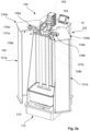
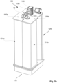
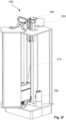
- FIGS 2a-f are principle drawings of separate cleaning assembly 100 for magnet assemblies 10.
- the separate cleaning assembly 100 is formed by a base 110 and main body 120 extending upwards from the base 110, as well as retaining means 130a-b for retaining the magnet assembly 10, and receiving means 140 for receiving and accommodating the wiper assembly 20 of the magnet assembly 10.
- the retaining means 130a-b according to the present invention are formed by two mirror doors 131a-b, arranged pivotable to the main body 120 at upper side and the base 110 at lower side thereof.
- the mirror doors 131a-b exhibit in the shown example a mainly triangular elongated shape which at lower end is provided with an exterior extending flange 132a-b provided with a hole 133a-b for connection to the base 110 via a pin or bolt (not shown).
- the mirror doors 131a-b are provided with an end plate 134a-b provided with an extending part with a hole 135a-b ( Figures 2d-e ) for connection to upper side of the main body 120 via a pin or bolt (not shown).
- the mirror doors 131a-b can further be arranged to driving means (not shown) for opening or closing the mirror doors 131a-b and/or locking means (not shown) for locking the doors in closed and/or open position.
- the end plates 134a-b of the mirror doors 131a-b are provided with corresponding recesses 136a-b at contact surfaces 137 thereof, such that when the mirror doors 131a-b are in contact with each other, the recesses 136a-b are adapted to receive, accommodate and retain the magnet handle device 14 of the magnet assembly 10, and thus retain the magnet assembly 10, as shown in Figure 2b .
- the contact surfaces 137a-b of the mirror doors 131a-b are further provided with recesses 138a-b adapted the handle 15 of the magnet assembly 10 allowing the mirror doors 131a-b to entirely contact each other with the contact surfaces 137a-b.
- the base 110, main body 120 and retaining means 130a-b/mirror doors 131a-b thus form a mainly rectangular housing or container with doors 131a-b that can be opened, as shown in Figure 2a , to receive a magnet assembly 10, and closed, as shown in Figure 2b , to retain the magnet assembly 10.
- the receiving means 140 for receiving and accommodating the wiper assembly 20 of the magnet assembly 10 is e.g. formed by a clamp, adapted the shape and size of the wiper assembly 20.
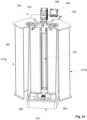
- the receiving means 140 for the wiper assembly 20 is arranged to a driving unit 150 arranged to move the wiper assembly 20 in longitudinal direction of the magnet rod(s) 11 of the magnet assembly 20.
- the receiving means 140 can further be provided with locking means for locking the wiper assembly 20 when inserted therein for increased safety during operation.
- the driving unit 150 is arranged movable in longitudinal direction of a vertically extending column 160, integrated or arranged to the main body 120.
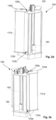
- the vertically extending column 160 is provided with a longitudinally extending guide track 161 ( Figure 2c ), at a longitudinal side thereof facing the magnet assembly 10/receiving means 140, and the driving unit 140 is extending through the longitudinally extending track 161 and is arranged movably to a vertically extending shaft 170 arranged in the vertically extending column 160, as shown in Figure 2f , where several parts have been removed revealing interior details.
- the driving unit 150 can be provided with an electric motor with a shaft with a toothed wheel arranged thereto which is in engagement with a toothed rack arranged in the vertically extending shaft 170.
- the driving unit 150 is provided with an electric motor with a shaft provided with driving wheels with high friction in engagement with the vertically extending shaft 170.
- the vertically extending shaft 170 is provided with threads (lead screw) and the driving unit 150 is provided with a threaded section/element (e.g. a nut) in engagement with the threads of the vertically extending shaft 170, and the vertical shaft 170 is arranged rotatable in the vertically extending column 160 and driven by an electric motor 180 arranged to the base 110, with transmission means (not shown) between the electric motor and vertically extending shaft arranged in the base 110.
- a threaded section/element e.g. a nut
- the driving mechanism of the driving unit 150 can also be realized with a belt drive instead of a lead screw.
- a magnet assembly 10 can be inserted into the separate cleaning assembly 100 by opening the doors 131a-b and wherein the magnet assembly 10 is received and held by that the wiper assembly 20, in upper position, is received and held by the receiving means 140.
- the mirror doors 131a-b are then closed and the recesses 136a-b receive, accommodate and enclose the magnet handle device 14 of the magnet assembly 10 and retain the magnet assembly 10.
- the driving unit 150 can then be activated and move the wiper assembly 20 downwards and upwards along the magnet rods 11 removing material attached thereto, one or several times until all material are removed from the exterior surface of the magnet rods 11. After the cleaning is completed, the mirror doors 131a-b are again opened and the magnet assembly 10 is ready for use.
- the separate cleaning assembly 100 it is further provided with weighing means 300 for weighing the removed material.
- the separate cleaning assembly 100 can be provided a load cell 300 arranged at lower part of the main body 120 or in the base 110, such that removed material (cuttings) can be registered.
- the removed material is preferably collected in a box or container 310 arranged on a collar 320 ( Figure 2c ) arranged to the load cell 300.
- the results of the measurement of the load cell 300 is preferably shown on a scale 330 arranged exterior of the cleaning assembly 100 or transferred to an exterior unit by means of the cleaning assembly 100 comprising a communication device.
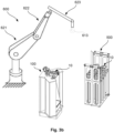
- Figure 3a-b shows examples of the use of manipulator systems 600 for insertion and removal of magnet assemblies 10 to and from the separate cleaning assembly 100 according to the present invention.
- Figure 3a-b is also show a typical example of area of use of the present invention, i.e. a device 500 comprising a numerous of magnet assemblies 10, as described in WO2016159779 , arranged in a material flow, and where the magnet assemblies 10 are to be cleaned when desired.
- the separate cleaning assembly 100 can be arranged in the vicinity of the device 500, and where manipulator systems 600, e.g. as in Figure 3a in the form of a monorail 610, a traverser carriage 611, and to the traverser carriage 611 arranged a lifting device 612.
- the lifting device 612 comprises a hook 613 adapted for connection to the magnet handle device 14 for lifting the magnet assembly 10 out of the device 500 and moving it to the separate cleaning assembly 100 by means of the traverser carriage 611 and inserting the magnet assembly 10 into the cleaning assembly 100.
- the magnet assembly 10 is next cleaned as described above, whereupon the magnet assembly 10 is removed from the cleaning assembly 100 and returned to the device 500 by means of the lifting device 612 and traverser carriage 611.
- Figure 3b is shown an alternative solution where the manipulator system 600 is formed by at least two manipulator arms 621-623 and wherein a hook 613 is arranged at a free end of the manipulator arm 623. By the manipulator arms 621-623 the magnet assembly 10 is moved and cleaned as described above for the monorail solution.
- the entire operation can be automated.
Landscapes
- Life Sciences & Earth Sciences (AREA)
- Engineering & Computer Science (AREA)
- Geology (AREA)
- Mining & Mineral Resources (AREA)
- Physics & Mathematics (AREA)
- Environmental & Geological Engineering (AREA)
- Fluid Mechanics (AREA)
- General Life Sciences & Earth Sciences (AREA)
- Geochemistry & Mineralogy (AREA)
- Marine Sciences & Fisheries (AREA)
- Mechanical Engineering (AREA)
- Cleaning In General (AREA)
- Reciprocating, Oscillating Or Vibrating Motors (AREA)
- Magnetically Actuated Valves (AREA)
Applications Claiming Priority (2)
| Application Number | Priority Date | Filing Date | Title |
|---|---|---|---|
| NO20180544A NO344126B1 (en) | 2018-04-20 | 2018-04-20 | Cleaning assembly for magnet assemblies |
| PCT/NO2019/050071 WO2019203656A1 (en) | 2018-04-20 | 2019-04-08 | Cleaning assembly for magnet assemblies |
Publications (4)
| Publication Number | Publication Date |
|---|---|
| EP3781322A1 EP3781322A1 (en) | 2021-02-24 |
| EP3781322A4 EP3781322A4 (en) | 2022-01-05 |
| EP3781322C0 EP3781322C0 (en) | 2024-03-06 |
| EP3781322B1 true EP3781322B1 (en) | 2024-03-06 |
Family
ID=67997747
Family Applications (1)
| Application Number | Title | Priority Date | Filing Date |
|---|---|---|---|
| EP19787624.6A Active EP3781322B1 (en) | 2018-04-20 | 2019-04-08 | Cleaning assembly for magnet assemblies |
Country Status (7)
| Country | Link |
|---|---|
| US (1) | US11684931B2 (no) |
| EP (1) | EP3781322B1 (no) |
| AU (1) | AU2019257116B2 (no) |
| BR (1) | BR112020021366A2 (no) |
| CA (1) | CA3097702A1 (no) |
| NO (1) | NO344126B1 (no) |
| WO (1) | WO2019203656A1 (no) |
Families Citing this family (2)
| Publication number | Priority date | Publication date | Assignee | Title |
|---|---|---|---|---|
| NO345634B1 (en) * | 2019-07-12 | 2021-05-18 | Jagtech As | Device for capturing and removing magnetic material from a flow of material |
| CN116493304B (zh) * | 2023-06-30 | 2023-11-03 | 宁德时代新能源科技股份有限公司 | 清洗装置、除杂系统和清洗方法 |
Family Cites Families (21)
| Publication number | Priority date | Publication date | Assignee | Title |
|---|---|---|---|---|
| DE3218791A1 (de) | 1981-05-27 | 1983-03-31 | Günther 8011 Pliening Deisenberger | Magnetabscheider fuer rieselfaehiges festes gut |
| US5043063A (en) | 1990-03-21 | 1991-08-27 | Eriez Manufacturing Company | Magnetic trap and cleaning means therefor |
| US5066390A (en) | 1990-06-04 | 1991-11-19 | Rhodes Keith J | Magnetic separator with reciprocating grate |
| US5188239A (en) | 1991-06-17 | 1993-02-23 | Industrial Magnetics, Inc. | Tramp metal separation device |
| US5190159A (en) | 1992-03-23 | 1993-03-02 | Eriez Manufacturing Company | Self-cleaning grate magnet and bushing |
| FR2718065B1 (fr) * | 1994-03-31 | 1996-05-31 | Tournier Alain Le | Dispositif de nettoyage automatique de barreaux de retenue de particules magnétisables en suspension dans un fluide. |
| US6250475B1 (en) * | 1998-05-01 | 2001-06-26 | Magnetic Products, Inc. | Permanent magnet separator having moveable stripper plate |
| KR200200851Y1 (ko) * | 2000-06-09 | 2000-10-16 | 양병곤 | 금속이물질 제거장치용 금속편 제거구 |
| US6638425B2 (en) * | 2001-03-28 | 2003-10-28 | Filter Specialists, Inc. | Magnetic filter |
| US6453738B1 (en) * | 2001-04-10 | 2002-09-24 | Cesmat Service Company, Inc. | Method and apparatus for analyzing casing wear and retrieval of metallic fragments |
| US8641899B2 (en) | 2007-05-09 | 2014-02-04 | Petroleum Specialty Rental, Llc | Method and apparatus for removing metal cuttings from an oil well drilling mud stream |
| WO2009124342A1 (en) | 2008-04-08 | 2009-10-15 | William John Baker | Magnetic separation apparatus |
| US20100065504A1 (en) * | 2008-04-30 | 2010-03-18 | Ping-Wen Yen | Novel filtration method for refining and chemical industries |
| CA2762034C (en) * | 2008-05-13 | 2016-07-12 | Roger M. Simonson | Pipeline magnetic separator system |
| US8132674B1 (en) * | 2009-04-22 | 2012-03-13 | Industrial Magnetics, Inc. | Continuous cleaning tramp metal separation device |
| US8474629B1 (en) * | 2010-05-24 | 2013-07-02 | Industrial Magnetics, Inc. | Self-cleaning tramp metal separation device for pneumatic conveying lines |
| DE102011118696A1 (de) * | 2011-11-16 | 2013-05-16 | Hacanoka Gmbh | Vorrichtung zur Auf- oder Entnahme von magnetischen oder magnetisierbaren Teilen |
| GB2518162B (en) | 2013-09-11 | 2016-02-03 | Eclipse Magnetics Ltd | Magnetic filtration apparatus |
| NO336314B1 (no) | 2013-09-23 | 2015-07-27 | Apply Rig & Modules As | Anordning og fremgangsmåte for fjerning av magnetisk materiale fra en fluidstrøm |
| NO341809B1 (en) * | 2015-03-30 | 2018-01-29 | Sapeg As | Device for capturing and removing magnetic material in a flow of material |
| GB201616947D0 (en) * | 2016-10-05 | 2016-11-23 | Romar International Limited | Apparatus and method for removing magnetic particles from liquids and slurries |
-
2018
- 2018-04-20 NO NO20180544A patent/NO344126B1/en unknown
-
2019
- 2019-04-08 EP EP19787624.6A patent/EP3781322B1/en active Active
- 2019-04-08 BR BR112020021366-7A patent/BR112020021366A2/pt unknown
- 2019-04-08 AU AU2019257116A patent/AU2019257116B2/en active Active
- 2019-04-08 US US17/049,188 patent/US11684931B2/en active Active
- 2019-04-08 WO PCT/NO2019/050071 patent/WO2019203656A1/en active Application Filing
- 2019-04-08 CA CA3097702A patent/CA3097702A1/en active Pending
Also Published As
| Publication number | Publication date |
|---|---|
| EP3781322C0 (en) | 2024-03-06 |
| BR112020021366A2 (pt) | 2021-01-19 |
| EP3781322A1 (en) | 2021-02-24 |
| NO344126B1 (en) | 2019-09-09 |
| WO2019203656A1 (en) | 2019-10-24 |
| AU2019257116B2 (en) | 2024-04-04 |
| US20210237099A1 (en) | 2021-08-05 |
| AU2019257116A1 (en) | 2020-11-26 |
| US11684931B2 (en) | 2023-06-27 |
| EP3781322A4 (en) | 2022-01-05 |
| CA3097702A1 (en) | 2019-10-24 |
Similar Documents
| Publication | Publication Date | Title |
|---|---|---|
| EP3781322B1 (en) | Cleaning assembly for magnet assemblies | |
| DE102011055899A1 (de) | Verfahren und eine Vorrichtung zum Handhaben von Probenbehältern | |
| KR20080105488A (ko) | 증기발생기 2차측 관판 상부의 전열관 다발 틈새 육안검사및 이물질 제거장치 | |
| NO20151424A1 (en) | Device for capturing and removing magnetic material in a flow of material | |
| CN109109003B (zh) | 一种牢固抓取机械手 | |
| CN104677677A (zh) | 一种投放式水体采集系统 | |
| CN104677682A (zh) | 一种定点触发式底层水保真采集器 | |
| CN104677676A (zh) | 一种采水器 | |
| CN208203118U (zh) | 岩土采样钻孔器 | |
| CN104729882A (zh) | 深海悬垂式水样气密采样器 | |
| US10706976B2 (en) | Assembly for acting on the outer surface of a tube, and corresponding method | |
| DE202007018443U1 (de) | Vorrichtung zum Bearbeiten eines Lager- und/oder Transportbehältnisses | |
| CN112534516A (zh) | 用于对核燃料组件进行干预的装置 | |
| CN207427645U (zh) | 一种plc自动化维护辅助装置 | |
| CN215199727U (zh) | 一种液压阀零件加工用钻孔装置 | |
| CN206263353U (zh) | 一种切管机自动下料装置 | |
| CN104677692A (zh) | 分层水体收集装置 | |
| CN209903130U (zh) | 具有收集灰尘功能的墙体钻孔机 | |
| CN209387326U (zh) | 一种便于使用的土壤治理用取样装置 | |
| KR101074344B1 (ko) | 배관 내부의 방사성 오염시료 채취장치 | |
| DE19654522C2 (de) | Einrichtung zum Entfernen von Proben aus einer Meßsonde | |
| DE3910614C2 (no) | ||
| CN216102155U (zh) | 一种水利工程用混凝土运输装置 | |
| DE4425370A1 (de) | Ferngesteuerter Greifer zum sicheren Greifen von Fässern in senkrechter und waagerechter Position ohne Raumverlust | |
| CN112660797B (zh) | 过滤器滤芯污水收集装置 |
Legal Events
| Date | Code | Title | Description |
|---|---|---|---|
| STAA | Information on the status of an ep patent application or granted ep patent |
Free format text: STATUS: THE INTERNATIONAL PUBLICATION HAS BEEN MADE |
|
| PUAI | Public reference made under article 153(3) epc to a published international application that has entered the european phase |
Free format text: ORIGINAL CODE: 0009012 |
|
| STAA | Information on the status of an ep patent application or granted ep patent |
Free format text: STATUS: REQUEST FOR EXAMINATION WAS MADE |
|
| 17P | Request for examination filed |
Effective date: 20201116 |
|
| AK | Designated contracting states |
Kind code of ref document: A1 Designated state(s): AL AT BE BG CH CY CZ DE DK EE ES FI FR GB GR HR HU IE IS IT LI LT LU LV MC MK MT NL NO PL PT RO RS SE SI SK SM TR |
|
| AX | Request for extension of the european patent |
Extension state: BA ME |
|
| DAV | Request for validation of the european patent (deleted) | ||
| DAX | Request for extension of the european patent (deleted) | ||
| A4 | Supplementary search report drawn up and despatched |
Effective date: 20211203 |
|
| RIC1 | Information provided on ipc code assigned before grant |
Ipc: B08B 9/023 20060101ALI20211129BHEP Ipc: B08B 1/00 20060101ALI20211129BHEP Ipc: B03C 1/28 20060101AFI20211129BHEP |
|
| P01 | Opt-out of the competence of the unified patent court (upc) registered |
Effective date: 20230526 |
|
| GRAP | Despatch of communication of intention to grant a patent |
Free format text: ORIGINAL CODE: EPIDOSNIGR1 |
|
| STAA | Information on the status of an ep patent application or granted ep patent |
Free format text: STATUS: GRANT OF PATENT IS INTENDED |
|
| INTG | Intention to grant announced |
Effective date: 20230925 |
|
| GRAS | Grant fee paid |
Free format text: ORIGINAL CODE: EPIDOSNIGR3 |
|
| GRAA | (expected) grant |
Free format text: ORIGINAL CODE: 0009210 |
|
| STAA | Information on the status of an ep patent application or granted ep patent |
Free format text: STATUS: THE PATENT HAS BEEN GRANTED |
|
| RAP3 | Party data changed (applicant data changed or rights of an application transferred) |
Owner name: JAGTECH AS |
|
| AK | Designated contracting states |
Kind code of ref document: B1 Designated state(s): AL AT BE BG CH CY CZ DE DK EE ES FI FR GB GR HR HU IE IS IT LI LT LU LV MC MK MT NL NO PL PT RO RS SE SI SK SM TR |
|
| REG | Reference to a national code |
Ref country code: CH Ref legal event code: EP |
|
| REG | Reference to a national code |
Ref country code: IE Ref legal event code: FG4D |
|
| REG | Reference to a national code |
Ref country code: DE Ref legal event code: R096 Ref document number: 602019047870 Country of ref document: DE |
|
| U01 | Request for unitary effect filed |
Effective date: 20240326 |
|
| U07 | Unitary effect registered |
Designated state(s): AT BE BG DE DK EE FI FR IT LT LU LV MT NL PT SE SI Effective date: 20240408 |
|
| U20 | Renewal fee paid [unitary effect] |
Year of fee payment: 6 Effective date: 20240404 |
|
| P04 | Withdrawal of opt-out of the competence of the unified patent court (upc) registered |
Effective date: 20240412 |