EP3780945B1 - Cultivation system for cultivating plants - Google Patents
Cultivation system for cultivating plants Download PDFInfo
- Publication number
- EP3780945B1 EP3780945B1 EP19716252.2A EP19716252A EP3780945B1 EP 3780945 B1 EP3780945 B1 EP 3780945B1 EP 19716252 A EP19716252 A EP 19716252A EP 3780945 B1 EP3780945 B1 EP 3780945B1
- Authority
- EP
- European Patent Office
- Prior art keywords
- filling
- cultivation
- water
- cultivation system
- connection
- Prior art date
- Legal status (The legal status is an assumption and is not a legal conclusion. Google has not performed a legal analysis and makes no representation as to the accuracy of the status listed.)
- Active
Links
- XLYOFNOQVPJJNP-UHFFFAOYSA-N water Substances O XLYOFNOQVPJJNP-UHFFFAOYSA-N 0.000 claims description 95
- 230000003287 optical effect Effects 0.000 claims description 8
- 238000011144 upstream manufacturing Methods 0.000 claims description 8
- 230000001580 bacterial effect Effects 0.000 claims description 6
- 239000011888 foil Substances 0.000 claims description 6
- 239000000758 substrate Substances 0.000 claims description 4
- 238000005520 cutting process Methods 0.000 claims description 3
- 230000003612 virological effect Effects 0.000 claims description 2
- 230000001419 dependent effect Effects 0.000 claims 1
- 101100298222 Caenorhabditis elegans pot-1 gene Proteins 0.000 description 53
- 241000196324 Embryophyta Species 0.000 description 21
- 230000012010 growth Effects 0.000 description 7
- 238000011109 contamination Methods 0.000 description 3
- 238000003780 insertion Methods 0.000 description 3
- 230000037431 insertion Effects 0.000 description 3
- 238000005259 measurement Methods 0.000 description 3
- 230000008635 plant growth Effects 0.000 description 3
- 238000007789 sealing Methods 0.000 description 3
- 239000012780 transparent material Substances 0.000 description 3
- 240000008415 Lactuca sativa Species 0.000 description 2
- 235000003228 Lactuca sativa Nutrition 0.000 description 2
- 241001529734 Ocimum Species 0.000 description 2
- 235000010676 Ocimum basilicum Nutrition 0.000 description 2
- 230000005791 algae growth Effects 0.000 description 2
- QVGXLLKOCUKJST-UHFFFAOYSA-N atomic oxygen Chemical compound [O] QVGXLLKOCUKJST-UHFFFAOYSA-N 0.000 description 2
- 238000012864 cross contamination Methods 0.000 description 2
- 238000002845 discoloration Methods 0.000 description 2
- 238000012544 monitoring process Methods 0.000 description 2
- 229910052760 oxygen Inorganic materials 0.000 description 2
- 239000001301 oxygen Substances 0.000 description 2
- 241000195493 Cryptophyta Species 0.000 description 1
- 239000000549 coloured material Substances 0.000 description 1
- 238000005202 decontamination Methods 0.000 description 1
- 230000003588 decontaminative effect Effects 0.000 description 1
- 230000007423 decrease Effects 0.000 description 1
- 238000011161 development Methods 0.000 description 1
- 230000018109 developmental process Effects 0.000 description 1
- 239000012530 fluid Substances 0.000 description 1
- 230000035784 germination Effects 0.000 description 1
- 238000003973 irrigation Methods 0.000 description 1
- 230000002262 irrigation Effects 0.000 description 1
- 239000000463 material Substances 0.000 description 1
- 238000012986 modification Methods 0.000 description 1
- 230000004048 modification Effects 0.000 description 1
- 230000003020 moisturizing effect Effects 0.000 description 1
- 235000015097 nutrients Nutrition 0.000 description 1
- 239000002689 soil Substances 0.000 description 1
- 238000004659 sterilization and disinfection Methods 0.000 description 1
Images


Classifications
-
- A—HUMAN NECESSITIES
- A01—AGRICULTURE; FORESTRY; ANIMAL HUSBANDRY; HUNTING; TRAPPING; FISHING
- A01G—HORTICULTURE; CULTIVATION OF VEGETABLES, FLOWERS, RICE, FRUIT, VINES, HOPS OR SEAWEED; FORESTRY; WATERING
- A01G27/00—Self-acting watering devices, e.g. for flower-pots
- A01G27/008—Component parts, e.g. dispensing fittings, level indicators
-
- A—HUMAN NECESSITIES
- A01—AGRICULTURE; FORESTRY; ANIMAL HUSBANDRY; HUNTING; TRAPPING; FISHING
- A01G—HORTICULTURE; CULTIVATION OF VEGETABLES, FLOWERS, RICE, FRUIT, VINES, HOPS OR SEAWEED; FORESTRY; WATERING
- A01G27/00—Self-acting watering devices, e.g. for flower-pots
- A01G27/006—Reservoirs, separate from plant-pots, dispensing directly into rooting medium
-
- A—HUMAN NECESSITIES
- A01—AGRICULTURE; FORESTRY; ANIMAL HUSBANDRY; HUNTING; TRAPPING; FISHING
- A01G—HORTICULTURE; CULTIVATION OF VEGETABLES, FLOWERS, RICE, FRUIT, VINES, HOPS OR SEAWEED; FORESTRY; WATERING
- A01G9/00—Cultivation in receptacles, forcing-frames or greenhouses; Edging for beds, lawn or the like
- A01G9/02—Receptacles, e.g. flower-pots or boxes; Glasses for cultivating flowers
- A01G9/029—Receptacles for seedlings
- A01G9/0293—Seed or shoot receptacles
-
- Y—GENERAL TAGGING OF NEW TECHNOLOGICAL DEVELOPMENTS; GENERAL TAGGING OF CROSS-SECTIONAL TECHNOLOGIES SPANNING OVER SEVERAL SECTIONS OF THE IPC; TECHNICAL SUBJECTS COVERED BY FORMER USPC CROSS-REFERENCE ART COLLECTIONS [XRACs] AND DIGESTS
- Y02—TECHNOLOGIES OR APPLICATIONS FOR MITIGATION OR ADAPTATION AGAINST CLIMATE CHANGE
- Y02P—CLIMATE CHANGE MITIGATION TECHNOLOGIES IN THE PRODUCTION OR PROCESSING OF GOODS
- Y02P60/00—Technologies relating to agriculture, livestock or agroalimentary industries
- Y02P60/20—Reduction of greenhouse gas [GHG] emissions in agriculture, e.g. CO2
- Y02P60/21—Dinitrogen oxide [N2O], e.g. using aquaponics, hydroponics or efficiency measures
Definitions
- the invention relates to a cultivation system for cultivating plants from e.g. seed, seedlings, cuttings, etc., arranged in or on substrate plugs at the top of the cultivation pots, in cultivation pots which are part of or are associated with the cultivation system.
- Such a cultivation system is generally known.
- Chinese patent publication CN 2722605 Y discloses a water-saving water storage type flower pot, wherein one or a plurality of tubes are arranged within the pot and extend upward from a hole in the bottom of the pot such that water can be stored therein.
- the one or the plurality of tubes allow watering of the flower pot through capillary principles.
- Chinese patent publication CN 203708968 U discloses a device for automatically watering a flower in a flower pot.
- the device comprises a water storage device and a water delivery pipe formed by a main pipe and a branch pipe. An upper end of the branch pipe is inserted upward into a flower pot from the bottom thereof, wherein the depth of insertion determines a moisturizing position in the flower pot.
- US patent publication US 2017/0188528 A1 discloses a self-watering planter device having an integral internal irrigation system, wherein distribution channels are provided that extend upward from a bottom end of the planter device and wherein the distribution channels have outer outlet orifices that are positioned within the planter device.
- US patent application US 2016/183488 A1 discloses a hydroponic cultivation apparatus which stores a nutrient synthesized in an above-ground part into an underground part, and is configured to water the underground part.
- Chinese patent publication CN 104172819 B discloses a plant cultivation system whereby filling channels are located in the pots and are connected to a dedicated water supply pipe. The system also includes means to measure the soil humidity.
- the present invention aims to provide a cultivation system of the above-mentioned type, provided with or comprising means for bringing up to standard the level of water in the cultivation pots used.
- a cultivation system of the above-mentioned type wherein the cultivation pots are each provided with a filling channel extending vertically upwards from a bottom and / or side wall, the filling channel being arranged to cooperate with a filling module which is part of or cooperates with the cultivation system, and which has one or more filling connections, each filling connection being arranged to engage with the filling channel for supplying the associated cultivation pot with sufficient water.
- the cultivation system comprises means for measuring the actual quantity of water or the actual water level in each associated cultivation pot and for additional filling with water in dependence thereof.
- the cultivation system comprises or utilizes at least one cultivation pot having a bottom wall, a (circumferential) side wall and a filling channel that extends upwards from the bottom and/or side wall.
- the cultivation system further comprises a filling module provided with at least one filling connection which is configured to cooperate/engage with the filling channel of the at least one cultivation pot for supplying the at least one cultivation pot with water.
- the cultivation system comprises means for measuring an actual quantity/amount of water and/or an actual water level in the at least one cultivation pot allowing control of the amount of water being supplied thereto.
- the cultivation system of the present invention may comprise any plurality of cultivation pots, wherein each cultivation pot has a bottom wall, a (circumferential) side wall and a filling channel that extends upwards from the bottom and/or side wall.
- the cultivation system then comprises a filling module provided with a (corresponding) plurality of filling connections each of which is configured to cooperate/engage with a filling channel of a cultivation pot of the plurality of cultivation pots for supplying water thereto.
- the cultivation system then comprises means for measuring an actual quantity/amount of water and/or an actual water level in each cultivation pot allowing control of the amount of water being supplied to each cultivation pot.
- the cultivation system according to the invention may also comprise means which are arranged to provide that the water level does not fall below a minimum level and does not exceed a maximum level, for the germination and J or further development of the seed etc. in the associated cultivation pot.
- the present invention also comprises a cultivation pot which is arranged to form part of, or at least to cooperate with, a cultivation system according to the invention as indicated above, which cultivation pot comprises a filling channel extending vertically upwards from a bottom and / or side wall, and arranged to be able to cooperate with the one or more filling connections of a filling module of the cultivation system in order to be able to provide the cultivation pot with sufficient water.
- Figs. 1a and 1b both show an exemplary embodiment of a cultivation system for cultivating plants from, for example, seed, seedlings, cuttings, etc., arranged in or on substrate plugs 2 in cultivation pots 1 belonging to, or at least cooperating with, the cultivation system (see for example http://www.bvb-substrates.nl/nieuwe-toepassing-bvb-sublime/) at the top of the cultivation pots, which are for example placed in lids 3 or foil applied to the cultivation pots.
- the cultivation pots 1 are each provided with a filling channel 5 extending vertically upwards from a bottom wall 4a (see Fig. 1a ) and / or side wall 4b (see Fig. 1b ), so as to cooperate with a filling module 6 belonging to the cultivation system or at least co-operating therewith, comprising a number of vertically upwardly extending filling connections 7, each of which is adapted to contact with the filling channel 5 of cultivation pots 1 in order to provide the associated cultivation pot 1 with water.
- the cultivation system comprises at least one cultivation pot 1 having a bottom wall 4a, a (circumferential) side wall 4b and a filling channel 5 that extends upwards from the bottom and/or side wall 4a, 4b.
- the cultivation system then comprises a filling module 6 provided with at least one filling connection 7 which is configured to cooperate/engage with the filling channel 5 of the at least one cultivation pot 1 for supplying water thereto. Therefore, given one or more cultivation pots 1, the filling module 6 comprises a corresponding one or more filling connections 7 each of which is configured to engage with the filling channel 5 of one of the one or more cultivation pots 1.
- the cultivation system shown comprises means, for instance a water supply control module 8, which ensures that the cultivation pots 1 are filled to such a level 9 that there is sufficient water for the plant for a certain period of time.
- the cultivation system comprises, for example, sensors for measuring the actual amount of water (for example by weight measurement, e.g. weight sensors) or the actual water level 9 (for example by optical sensors) in each associated cultivation pot 1, and for supplying a quantity of water to each cultivation pot 1 in dependence thereof.
- sensors for measuring the actual amount of water for example by weight measurement, e.g. weight sensors
- the actual water level 9 for example by optical sensors
- the filling channel 5 extends upwards and has a substantial length which is such that if the cultivation pots 1 are removed after filling with water from the filling module 6, the water cannot flow away via the filling channel 5. Due to the large length of the filling channel 5, an amount of water remains in the cultivation pot 1 such that the plant to be grown in the plug 2 has sufficient water for a longer period of time. Because the plant roots develop in length while the water level drops, the plant will thus have sufficient water for a longer period of time, for example a week.
- Fig. 1a shows an exemplary embodiment of a cultivation system in which the cultivation pots 1 are each provided with a filling channel 5 extending vertically upwards from the bottom wall 4a, arranged to cooperate with the filling module 6 comprising a number of vertically upwardly extending filling connections 7, each arranged to make contact with the filling channel 5 of the cultivation pots 1 in order to be able to provide them with water.
- water is provided through the filling connection 7 and through the filling channel 5, wherein the filling channel 5 comprises an upper opening extending above the water level 9.
- each filling connection 7 and each filling channel 5 comprises a passageway through which water can flow. So when a filling connection 7 is in engagement with a filling channel 5 of a cultivation pot 1, then the passageways of the filling connection 7 and the filling channel 5 are fluidly connected.
- each of the filling connections 7 comprises a tapered upper part for congruent engagement within a tapered lower part of the filling channel 5.
- This embodiment allows for good leak free sealing between the filling connection 7 and the filling channel 5, so that water may be pushed upwards in leak free fashion and through the upper opening of filling channel 5 into the cultivation pot 1.
- the tapered upper part and tapered lower part of the filling connection 7 and the filling channel 5, respectively, also provide improved alignment, such as improved alignment of the aforementioned passageways.
- the tapered upper part of each filling connection 7 and the tapered lower part of each filling channel 5 are conical shaped such that further sealing is provided and alignment is improved, e.g. alignment of the aforementioned passageways through the filling connection 7 and filling channel 5.
- An important advantage of having the above mentioned tapered/conical upper part and tapered/conical lower part for a filling connection 7 and a filling channel 5, respectively, is that bacterial and/or algae contamination of water in a cultivation pot 1 is reduced.
- Fig. 1b shows an exemplary embodiment of a cultivation system in which the cultivation pots 1 are each provided with a filling channel 5 extending vertically upwards partly from the bottom wall 4a and partly from the side wall 4b, arranged to cooperate with the filling module 6 which has a number of vertical upwardly extending filling connections 7, each adapted to be able to contact with the filling channel 5 of the cultivation pots 1 in order to be able to provide them with water.
- the filling channel 5 extends vertically upwardly (partially) from the (obliquely extending) side wall 4b
- the filling connections 7 are for that reason longer in order to obtain sufficient sealing with the filling channel 5.
- the filling channel 5 of a cultivation pot 1 may be offset from the centre/middle of the cultivation pot 1. This allows the plug 2 to be provided in the centre/middle of the cultivation pot 1 for providing maximum space around the plug 2 for cultivating a plant, particularly maximizing space for plant roots to grow in the water. So by offsetting the filling channel 5, obstruction to plant growth in the cultivation pot 1 is minimized.
- offsetting the filling channel 5 allows for better use of space, so that plant growth in width direction rather than height or in upward direction is facilitated. Lettuce, for instance, grows much more in width rather than height and as such having an offset filling channel 5 allows lettuce to symmetrically expand in all directions without interference with the offset filling channel 5. A plant such as Basil, on the other, grows much more in height rather than width and so a more centrally located filling channel 5 need not interfere with the growth cycle of Basil.
- the cultivation pots 1 can be provided with water from below, from the filling module 6, wherein the water flows into the top of the cultivation pot 1 (see figs. 1a and 1b ) via the high positioned outlet opening of the filling channel 5.
- the cultivation pots 1 can simply be connected to the filling connections 7 by placing them (from above) onto the filling module 6, and can then be removed from the filling connections 7 again by simply moving the cultivation pots upwards. It should be clear that in this manner (if desired) several cultivation pots can be connected simultaneously (for example per complete tray) to the filling module 6 and can be removed again simultaneously thereafter without having to connect and later disconnect the water connections in a separate operation / movement.
- each cultivation pot 1 may be provided with a perforated foil 3 configured for covering the cultivation pot 1 when in use.
- the perforated foil 3 covers the cultivation pot 1 but does allow for airto escape when water flows into the cultivation pot 1 as the volume above the water level 9 decreases when the water level 9 rises.
- the perforated foil 3 also improves exchange of oxygen to the cultivation pot 1 and in particular the water contained therein for optimized growth.
- the perforated foil 3 comprises perforations between 80 to 100 microns in size, allowing for further improved air and oxygen exchange.
- the cultivation pots 1 are transparent, i.e. made of transparent material, so that the growth of roots in the water can be checked and/or water discoloration can be checked, wherein water discoloration could be indicative of unwanted algae growth.
- the cultivation pots 1 are made of a non-transparent material, e.g. a white or coloured material, possibly translucent material. In case of such a non-transparent material, algae growth will be hindered, minimized, or even completely prevented.
- Fig. 2 shows a filling connection 7 according to an embodiment of the present invention.
- each filling connection 7 has a tapered shape along its entire length for congruent engagement within a tapered shape along the entire length of the filling channel 5.
- a tapered shape is provided to the entire length/height of the filling connection 7 and a tapered shape is provide to the entire length/height of the filling channel 5.
- each filling connection 7 comprises an upper water orifice 7a configured to extend beyond an top opening of the filling channel 5 when the filling connection 7 extends through the filling channel 5 of the cultivation pot 1 when in use.
- Another advantage of this embodiment is that leakage between the filling connection 7 and the filling channel 5 is reduced as there is a direct flow through the passageway that completely extends through the filling connection 7 toward the upper water orifice 7a.
- the upper water orifice 7a of each filling connection 7 is arranged in a side face thereof.
- water is being supplied in sideways fashion into the cultivation pot 1, so that it is possible to direct the supplied water through the upper water orifice 7a away from the plug 2, e.g. away from plant roots to avoid damage thereof.
- This may be achieved by directing the upper water orifice 7a toward the side wall 4b of the cultivation pot 1, which would also minimize splatter.
- the upper water orifice 7a may also be directed toward a corner of e.g. a rectangular/square cultivation pot 1, so that damage to the plant or roots thereof is prevented and splatter is reduced.
- the filter module 6 may further comprise a (bacterial, viral, etc.) filter 12 for each filling connection 7, and wherein the filter 12 is arranged upstream from the filling connection 7.
- the filter 12 prevents bacterial contamination from a water source 15 of the filter module 6, as water supplied by the water source 15 must first pass through the filter 12 before entering the filling connection 7 toward the cultivation pot 1.
- the filter module 6 may comprises a steam source 14 for each filling connection 7 and wherein the steam source 14 is arranged upstream from the filling connection 7.
- the passageway extending there through can be sterilized/decontaminated.
- the filter module 6 may comprise a filter 12 and a steam source 14 for each filling connection 7, wherein the filter 12 is arranged upstream from the filling connection 7 and wherein the steam source 14 may be arranged upstream from the filter 12.
- the steam source 14 allows for sterilisation of the filter 12 as well as the filling connection 7.
- the water source 15 and steam source 14 may be connected to a main supply tube 11 which is in turn connected to the filling connection 7, wherein the supply of steam from the steam source 14 and the supply of water from the water source 15 may be controlled through an appropriate valve arrangement.
- the (bacterial) filter 12 may be connected to the main supply tube 11 upstream therefrom, and wherein the steam source 14 and water source 15 may be connected to a filter supply tube 13 connected to the (bacterial) filter 12 upstream therefrom.
- each filling connection 7 may comprise one or more suction openings 7c configured for suction engagement with an inner wall of the filling channel 5.
- the filling connection 7 may be fully inserted into the filling channel 5 such that the one or more suction openings 7c engage the inner wall of the filling channel 5. Then by providing a vacuum or negative pressure at the suction openings 7c, the filling channel 5 and filling connection 7 can be forced into snug and tight engagement as a result of which an improved leak feel seal is provided between the filling channel 5 and filling connection 7. Also, through suction the cultivation pots 1 are sufficiently secured to the filling connection 7.
- filling connecting 7 and the filling channel 5 each comprise a tapered or conical shape for congruent engagement
- suction provided at the one or more suction openings 7c the filling connection 7 is forced further into the filling channel 5 up to a maximum depth, thereby further facilitating a snug and fluid tight seal between the filling channel 5 and filling connection 7.
- the filling connection 7 comprises the aforementioned passageway 7b connected to the upper water orifice 7a for supplying water to the cultivation pot 1.
- the passageway 7b is then connected to the water source 15 by means of the connection inlet 7f of the filling connection 7.
- the one or more suction openings 7c may be connected to secondary passageways 7d extending through the filling connection 7, and wherein the secondary passageways 7d may then be connected to suction inlets 7e of the filling connection 7.
- the suction inlets 7e are connected to a vacuum or negative pressure source (not shown).
- the suction inlets 7e may also be connected to a combined positive pressure source and vacuum/negative pressure source, so that the one or more suction openings 7c may be used for providing a vacuum/negative pressure or a positive pressure.
- the positive pressure may facilitate disconnecting the filling connection 7 from the filling channel 5 by separating them through a positive pressure at the one or more suction outlets 7c.
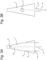
- the one or more suction openings 7c of each filling connection 7 may be arranged substantially along a mid-section thereof. As shown in Fig. 3a and 3b , the one or more suction openings 7c may be arranged substantially midway/halfway the length of the filling connection 7, so that parts of the filling connection 7 below and above the one or more suction openings 7c experience a similar vacuum/negative or positive pressure between the inner wall of the filling channel 5 and the filling connection 7.
- the one or more suction openings 7c are arranged in a side face/surface of the filling connection 7, wherein, in a further embodiment, the side face/surface may be a tapered surface, e.g. a conical surface.
- Fig. 4 shows an embodiment of a support table 20 according to the present invention.
- the cultivation system may comprise a support table 20 provided with at least one upward extending support post 21 comprising an upper end having a filling connection 7 attached thereto.
- the support post 21 allows a cultivation pot 1 to be positioned on a filling connection 7 away from the support table 20, so that the cultivation pot 1 can be handled by an automated pick-and-place system more easily as there is less interference from the support table 20.
- an automated pick-and-place system may be an automated crate system, wherein a crate is used to lower and lift the cultivation pot 1 to and away from the support table 20, i.e. the filling connection 7.
- the upper end of the support post 21 may comprise a support base 22 arranged (directly) below the filling connection 7, e.g. at the connection inlet 7f, wherein the support base 22 is configured to support the cultivation pot 1 when in use.
- the cultivation pot 1 rests on the support base 22, which may then determine the insertion depth of the filling connection 7 into the filling channel 5 of the cultivation pot 1.
- the filling connection 7 may be arranged offset from a centre point of the support base 22, thereby allowing for a cultivation pot 1 which is provided with a filling channel 5 offset from the centre/middle of the cultivation pot 1.
- This embodiment allows full support of the bottom wall 4a of the cultivation pot 1 whilst allowing offset placement of the filling channel 5.
- the support post 21 may be provided with a weight sensor and/or optical sensor configured to determine the water weight and/or water level 9, respectively, in a cultivation pot 1 when in use.
- the weight and/or optical sensor may be arranged on the support base 22. This allows close monitoring of the amount of water in the cultivation pot 1 and based on the measurements the supply of water can be controlled.
- Fig. 4 also shows how the support table 20 allows managing and handling of a plurality of cultivation pots 1.
- the cultivation system may comprise the support table 20 which is then provided with an array arrangement of at least two upward extending spaced apart support posts 21 each of which comprises an upper end having a filling connection 7 attached thereto.
- the at least two support posts 21 then have different heights with respect to the support table 20.
- the two spaced apart support posts 21 have different heights so that interference between plants of two adjacent cultivation pots 1 is prevented. This improves growth and prevents tangling of adjacent plants which would make placement and/or removal of the at least two cultivation pots 1 difficult.
- each of the at least two support posts 21 may comprise a support base 22 which is arranged (directly) below the filling connection 7, e.g. at the connection inlet 7f, wherein each support base 22 is configured to support a cultivation pot 1 when in use.
- each cultivation pot 1 is positioned on a respective support base 22 when in use, so that each support base 22 determines the insertion depth of the filling connection 7 into the filling channel 5 of the cultivation pot 1 supported on the respective support base 22.
- each filling connection 7 is arranged offset from a centre point of the support base 22, which is arranged (directly) below the filling connection 7, e.g. at the connection inlet 7f. This allows full support of the bottom wall 4a of the cultivation pot 1 whilst allowing offset placement of the fillings channel 5.
- providing an offset filling channel 5 to a cultivation pot 1 allows for efficient use of the cultivation pot 1 for plant varieties that tend to grow much more in width rather than height.
- By arranging each filling connection 7 offset from the centre point of the support base 22 allows for offset placement of each filling channel 5 whilst providing stable support to the cultivation pot 1.
- each support post 21 is provided with a weight sensor and/or optical sensor configured to determine a water weight and/or a water level, respectively, in the cultivation pot 1 supported on the support post 21 when in use.
- a weight sensor and/or optical sensor may be arranged on the support base 22 in a further embodiment.
- a weight sensor may be arranged directly underneath the support base 22 for measuring the weight of a cultivation pot 1 positioned on the support base 22. It is also conceivable that in an alternative embodiment the weight sensor is arranged directly on top of the support base 22 and configured to directly engage a cultivation pot 1.
- the support table 20 may be provided with an array arrangement of any plurality of upward extending spaced apart support posts 21, each of which comprises an upper end having a filling connection 7 attached thereto.
- the array arrangement forms a staggered/alternating arrangement of spaced apart support posts 21 with respect to height.
- any plurality of cultivation pots 1 can be used whilst preventing interference between the plants grown therein.
- Such a staggered/alternating arrangement of cultivation pots 1 at different heights also facilitates automated removal and placement of the cultivation pots 1.
- a (square) staggered/alternating arrangement of spaced apart support posts 21 is depicted based on two different heights.
- an automated crate positioning system it is possible to first remove cultivation pots 1 at the highest position with respect to the support table 20. This would yield a crate carrying a "checkerboard pattern" of spaced apart cultivation pots 1, allowing further growth of the plants kept in the cultivation pots 1 as there is more space for growth there between.
- Another crate may then be used to remove the cultivation pots 1 at the lowest position with respect the support table 20. This also yields a crate carrying a "checkerboard pattern" of spaced apart cultivation pots 1 to enable further growth of the plants kept therein.
- Fig. 4 further shows that the support table 20 may be connected to a water source by means of a hose or tube 23, and wherein the support table 20 may be provided with an electronic module 24 for e.g. connection to weight and/or optical sensors, water and/or steam valves etc.
Landscapes
- Life Sciences & Earth Sciences (AREA)
- Environmental Sciences (AREA)
- Engineering & Computer Science (AREA)
- Water Supply & Treatment (AREA)
- Cultivation Receptacles Or Flower-Pots, Or Pots For Seedlings (AREA)
- Hydroponics (AREA)
Description
- The invention relates to a cultivation system for cultivating plants from e.g. seed, seedlings, cuttings, etc., arranged in or on substrate plugs at the top of the cultivation pots, in cultivation pots which are part of or are associated with the cultivation system.
- Such a cultivation system is generally known.
- Chinese patent publication
CN 2722605 Y discloses a water-saving water storage type flower pot, wherein one or a plurality of tubes are arranged within the pot and extend upward from a hole in the bottom of the pot such that water can be stored therein. The one or the plurality of tubes allow watering of the flower pot through capillary principles. - Chinese patent publication
CN 203708968 U discloses a device for automatically watering a flower in a flower pot. The device comprises a water storage device and a water delivery pipe formed by a main pipe and a branch pipe. An upper end of the branch pipe is inserted upward into a flower pot from the bottom thereof, wherein the depth of insertion determines a moisturizing position in the flower pot. - US patent publication
US 2017/0188528 A1 discloses a self-watering planter device having an integral internal irrigation system, wherein distribution channels are provided that extend upward from a bottom end of the planter device and wherein the distribution channels have outer outlet orifices that are positioned within the planter device. - US patent application
US 2016/183488 A1 discloses a hydroponic cultivation apparatus which stores a nutrient synthesized in an above-ground part into an underground part, and is configured to water the underground part. Chinese patent publicationCN 104172819 B discloses a plant cultivation system whereby filling channels are located in the pots and are connected to a dedicated water supply pipe. The system also includes means to measure the soil humidity. - The present invention aims to provide a cultivation system of the above-mentioned type, provided with or comprising means for bringing up to standard the level of water in the cultivation pots used.
- To that end, according to the invention, there is provided a cultivation system of the above-mentioned type, wherein the cultivation pots are each provided with a filling channel extending vertically upwards from a bottom and / or side wall, the filling channel being arranged to cooperate with a filling module which is part of or cooperates with the cultivation system, and which has one or more filling connections, each filling connection being arranged to engage with the filling channel for supplying the associated cultivation pot with sufficient water.
- The cultivation system comprises means for measuring the actual quantity of water or the actual water level in each associated cultivation pot and for additional filling with water in dependence thereof.
- In particular, according to the present invention, the cultivation system comprises or utilizes at least one cultivation pot having a bottom wall, a (circumferential) side wall and a filling channel that extends upwards from the bottom and/or side wall. The cultivation system further comprises a filling module provided with at least one filling connection which is configured to cooperate/engage with the filling channel of the at least one cultivation pot for supplying the at least one cultivation pot with water. The cultivation system comprises means for measuring an actual quantity/amount of water and/or an actual water level in the at least one cultivation pot allowing control of the amount of water being supplied thereto.
- Note that the cultivation system of the present invention may comprise any plurality of cultivation pots, wherein each cultivation pot has a bottom wall, a (circumferential) side wall and a filling channel that extends upwards from the bottom and/or side wall. The cultivation system then comprises a filling module provided with a (corresponding) plurality of filling connections each of which is configured to cooperate/engage with a filling channel of a cultivation pot of the plurality of cultivation pots for supplying water thereto. The cultivation system then comprises means for measuring an actual quantity/amount of water and/or an actual water level in each cultivation pot allowing control of the amount of water being supplied to each cultivation pot.
- The cultivation system according to the invention may also comprise means which are arranged to provide that the water level does not fall below a minimum level and does not exceed a maximum level, for the germination and J or further development of the seed etc. in the associated cultivation pot.
- The present invention also comprises a cultivation pot which is arranged to form part of, or at least to cooperate with, a cultivation system according to the invention as indicated above, which cultivation pot comprises a filling channel extending vertically upwards from a bottom and / or side wall, and arranged to be able to cooperate with the one or more filling connections of a filling module of the cultivation system in order to be able to provide the cultivation pot with sufficient water.
- The present invention will now be further discussed with reference to the figure description below, in which
-
Figure 1a shows an embodiment of a cultivation pot of a cultivation system according to the present invention; -
Figure 1b shows an alternative embodiment of a cultivation pot of a cultivation system according to the present invention; -
Figure 2 shows a filling connection according to an embodiment of the present invention; -
Figure 3a and 3b each show an embodiment of a filling connection with a suction opening according to the present invention; and wherein -
Figure 4 shows an embodiment of a support table according to the present invention. -
Figs. 1a and 1b both show an exemplary embodiment of a cultivation system for cultivating plants from, for example, seed, seedlings, cuttings, etc., arranged in or onsubstrate plugs 2 incultivation pots 1 belonging to, or at least cooperating with, the cultivation system (see for example http://www.bvb-substrates.nl/nieuwe-toepassing-bvb-sublime/) at the top of the cultivation pots, which are for example placed inlids 3 or foil applied to the cultivation pots. - The
cultivation pots 1 are each provided with a fillingchannel 5 extending vertically upwards from abottom wall 4a (seeFig. 1a ) and / orside wall 4b (seeFig. 1b ), so as to cooperate with afilling module 6 belonging to the cultivation system or at least co-operating therewith, comprising a number of vertically upwardly extendingfilling connections 7, each of which is adapted to contact with thefilling channel 5 ofcultivation pots 1 in order to provide the associatedcultivation pot 1 with water. - According to the present invention there is no intrinsic limit to the number of
cultivation pots 1 utilized, so that the cultivation system comprises at least onecultivation pot 1 having abottom wall 4a, a (circumferential)side wall 4b and a fillingchannel 5 that extends upwards from the bottom and/orside wall filling module 6 provided with at least onefilling connection 7 which is configured to cooperate/engage with thefilling channel 5 of the at least onecultivation pot 1 for supplying water thereto. Therefore, given one ormore cultivation pots 1, thefilling module 6 comprises a corresponding one ormore filling connections 7 each of which is configured to engage with thefilling channel 5 of one of the one ormore cultivation pots 1. - The cultivation system shown comprises means, for instance a water supply control module 8, which ensures that the
cultivation pots 1 are filled to such alevel 9 that there is sufficient water for the plant for a certain period of time. The cultivation system comprises, for example, sensors for measuring the actual amount of water (for example by weight measurement, e.g. weight sensors) or the actual water level 9 (for example by optical sensors) in each associatedcultivation pot 1, and for supplying a quantity of water to eachcultivation pot 1 in dependence thereof. Thus,several cultivation pots 1 can be provided with a sufficient quantity of water at the same time. - The
filling channel 5 extends upwards and has a substantial length which is such that if thecultivation pots 1 are removed after filling with water from thefilling module 6, the water cannot flow away via thefilling channel 5. Due to the large length of thefilling channel 5, an amount of water remains in thecultivation pot 1 such that the plant to be grown in theplug 2 has sufficient water for a longer period of time. Because the plant roots develop in length while the water level drops, the plant will thus have sufficient water for a longer period of time, for example a week. -
Fig. 1a shows an exemplary embodiment of a cultivation system in which thecultivation pots 1 are each provided with afilling channel 5 extending vertically upwards from thebottom wall 4a, arranged to cooperate with thefilling module 6 comprising a number of vertically upwardly extendingfilling connections 7, each arranged to make contact with thefilling channel 5 of thecultivation pots 1 in order to be able to provide them with water. As depicted, water is provided through thefilling connection 7 and through the fillingchannel 5, wherein thefilling channel 5 comprises an upper opening extending above thewater level 9. As is readily understood that eachfilling connection 7 and each fillingchannel 5 comprises a passageway through which water can flow. So when afilling connection 7 is in engagement with a fillingchannel 5 of acultivation pot 1, then the passageways of thefilling connection 7 and the fillingchannel 5 are fluidly connected. - In an embodiment, as depicted in
Fig. 1a , each of thefilling connections 7 comprises a tapered upper part for congruent engagement within a tapered lower part of thefilling channel 5. This embodiment allows for good leak free sealing between thefilling connection 7 and the fillingchannel 5, so that water may be pushed upwards in leak free fashion and through the upper opening of fillingchannel 5 into thecultivation pot 1. The tapered upper part and tapered lower part of thefilling connection 7 and the fillingchannel 5, respectively, also provide improved alignment, such as improved alignment of the aforementioned passageways. - In an advantageous embodiment, the tapered upper part of each
filling connection 7 and the tapered lower part of each fillingchannel 5 are conical shaped such that further sealing is provided and alignment is improved, e.g. alignment of the aforementioned passageways through thefilling connection 7 and fillingchannel 5. - An important advantage of having the above mentioned tapered/conical upper part and tapered/conical lower part for a
filling connection 7 and a fillingchannel 5, respectively, is that bacterial and/or algae contamination of water in acultivation pot 1 is reduced. -
Fig. 1b shows an exemplary embodiment of a cultivation system in which thecultivation pots 1 are each provided with afilling channel 5 extending vertically upwards partly from thebottom wall 4a and partly from theside wall 4b, arranged to cooperate with thefilling module 6 which has a number of vertical upwardly extendingfilling connections 7, each adapted to be able to contact with thefilling channel 5 of thecultivation pots 1 in order to be able to provide them with water. In this embodiment, in which thefilling channel 5 extends vertically upwardly (partially) from the (obliquely extending)side wall 4b, thefilling connections 7 are for that reason longer in order to obtain sufficient sealing with thefilling channel 5. - From
Fig. 1a and 1b it follows that in an advantageous embodiment the fillingchannel 5 of acultivation pot 1 may be offset from the centre/middle of thecultivation pot 1. This allows theplug 2 to be provided in the centre/middle of thecultivation pot 1 for providing maximum space around theplug 2 for cultivating a plant, particularly maximizing space for plant roots to grow in the water. So by offsetting the fillingchannel 5, obstruction to plant growth in thecultivation pot 1 is minimized. - Furthermore, by offsetting the filling
channel 5 allows for better use of space, so that plant growth in width direction rather than height or in upward direction is facilitated. Lettuce, for instance, grows much more in width rather than height and as such having an offset fillingchannel 5 allows lettuce to symmetrically expand in all directions without interference with the offset fillingchannel 5. A plant such as Basil, on the other, grows much more in height rather than width and so a more centrally located fillingchannel 5 need not interfere with the growth cycle of Basil. - So by positioning the filling
channel 5 in offset fashion with respect to thecultivation pot 1, a cultivation pot area can be utilized more efficiently for plant varieties that grow in width rather than height. In both embodiments it is ensured that thecultivation pots 1 can be provided with water from below, from the fillingmodule 6, wherein the water flows into the top of the cultivation pot 1 (seefigs. 1a and 1b ) via the high positioned outlet opening of the fillingchannel 5. In addition, it is achieved that thecultivation pots 1 can simply be connected to thefilling connections 7 by placing them (from above) onto thefilling module 6, and can then be removed from thefilling connections 7 again by simply moving the cultivation pots upwards. It should be clear that in this manner (if desired) several cultivation pots can be connected simultaneously (for example per complete tray) to thefilling module 6 and can be removed again simultaneously thereafter without having to connect and later disconnect the water connections in a separate operation / movement. - In an advantageous embodiment, each
cultivation pot 1 may be provided with aperforated foil 3 configured for covering thecultivation pot 1 when in use. In this embodiment theperforated foil 3 covers thecultivation pot 1 but does allow for airto escape when water flows into thecultivation pot 1 as the volume above thewater level 9 decreases when thewater level 9 rises. Theperforated foil 3 also improves exchange of oxygen to thecultivation pot 1 and in particular the water contained therein for optimized growth. In a further embodiment, theperforated foil 3 comprises perforations between 80 to 100 microns in size, allowing for further improved air and oxygen exchange. - In an advantageous embodiment, the
cultivation pots 1 are transparent, i.e. made of transparent material, so that the growth of roots in the water can be checked and/or water discoloration can be checked, wherein water discoloration could be indicative of unwanted algae growth. In an alternative embodiment, thecultivation pots 1 are made of a non-transparent material, e.g. a white or coloured material, possibly translucent material. In case of such a non-transparent material, algae growth will be hindered, minimized, or even completely prevented. -
Fig. 2 shows afilling connection 7 according to an embodiment of the present invention. In the embodiment shown, each fillingconnection 7 has a tapered shape along its entire length for congruent engagement within a tapered shape along the entire length of the fillingchannel 5. So in contrast to the embodiments ofFig. 1a, 1b , a tapered shape is provided to the entire length/height of thefilling connection 7 and a tapered shape is provide to the entire length/height of the fillingchannel 5. Further, each fillingconnection 7 comprises anupper water orifice 7a configured to extend beyond an top opening of the fillingchannel 5 when thefilling connection 7 extends through the fillingchannel 5 of thecultivation pot 1 when in use. So when thefilling connection 7 is fully received within the fillingchannel 5, theupper water orifice 7a extend beyond the upper opening of the fillingchannel 5. This embodiment provides a distinct advantage in that cross contamination betweencultivation pots 1 is reduced as thefilling connection 7 does not come into contact with water contained in acultivation pot 1. So in case thefilling connection 7 is withdrawn from a fillingchannel 5 of a first cultivation pot, and subsequently inserted into a fillingchannel 5 of a second cultivation pot, then cross contamination from water contained in thefirst cultivation pot 1 to water contained in the second cultivation pot will not occur. - Another advantage of this embodiment is that leakage between the filling
connection 7 and the fillingchannel 5 is reduced as there is a direct flow through the passageway that completely extends through thefilling connection 7 toward theupper water orifice 7a. - In an advantageous embodiment, the
upper water orifice 7a of each fillingconnection 7 is arranged in a side face thereof. In this embodiment water is being supplied in sideways fashion into thecultivation pot 1, so that it is possible to direct the supplied water through theupper water orifice 7a away from theplug 2, e.g. away from plant roots to avoid damage thereof. This may be achieved by directing theupper water orifice 7a toward theside wall 4b of thecultivation pot 1, which would also minimize splatter. Note that theupper water orifice 7a may also be directed toward a corner of e.g. a rectangular/square cultivation pot 1, so that damage to the plant or roots thereof is prevented and splatter is reduced. - As further shown in
Fig. 2 , in an embodiment thefilter module 6 may further comprise a (bacterial, viral, etc.)filter 12 for each fillingconnection 7, and wherein thefilter 12 is arranged upstream from the fillingconnection 7. In this embodiment thefilter 12 prevents bacterial contamination from awater source 15 of thefilter module 6, as water supplied by thewater source 15 must first pass through thefilter 12 before entering thefilling connection 7 toward thecultivation pot 1. - Further or alternative anti-contamination measures can be envisaged. In an exemplary embodiment, the
filter module 6 may comprises asteam source 14 for each fillingconnection 7 and wherein thesteam source 14 is arranged upstream from the fillingconnection 7. By forcing steam through thefilling connection 7, the passageway extending there through can be sterilized/decontaminated. - It is even possible to combine the
filter 12 and thesteam source 14 to provide further decontamination of water supplied to thecultivation pots 1. For example, in an embodiment, thefilter module 6 may comprise afilter 12 and asteam source 14 for each fillingconnection 7, wherein thefilter 12 is arranged upstream from the fillingconnection 7 and wherein thesteam source 14 may be arranged upstream from thefilter 12. In this embodiment thesteam source 14 allows for sterilisation of thefilter 12 as well as thefilling connection 7. - As further depicted in
Fig. 2 , thewater source 15 andsteam source 14 may be connected to amain supply tube 11 which is in turn connected to thefilling connection 7, wherein the supply of steam from thesteam source 14 and the supply of water from thewater source 15 may be controlled through an appropriate valve arrangement. In an embodiment, the (bacterial)filter 12 may be connected to themain supply tube 11 upstream therefrom, and wherein thesteam source 14 andwater source 15 may be connected to afilter supply tube 13 connected to the (bacterial)filter 12 upstream therefrom. - With regard to the engagement between the filling
connection 7 and the fillingchannel 5 of acultivation pot 1,Fig. 3a and 3b each show a further embodiment of afilling connection 7 according to the present invention. In the embodiment shown, each fillingconnection 7 may comprise one ormore suction openings 7c configured for suction engagement with an inner wall of the fillingchannel 5. In this embodiment thefilling connection 7 may be fully inserted into the fillingchannel 5 such that the one ormore suction openings 7c engage the inner wall of the fillingchannel 5. Then by providing a vacuum or negative pressure at thesuction openings 7c, the fillingchannel 5 and fillingconnection 7 can be forced into snug and tight engagement as a result of which an improved leak feel seal is provided between the fillingchannel 5 and fillingconnection 7. Also, through suction thecultivation pots 1 are sufficiently secured to thefilling connection 7. - In case the filling connecting 7 and the filling
channel 5 each comprise a tapered or conical shape for congruent engagement, then through suction provided at the one ormore suction openings 7c thefilling connection 7 is forced further into the fillingchannel 5 up to a maximum depth, thereby further facilitating a snug and fluid tight seal between the fillingchannel 5 and fillingconnection 7. - In
Fig. 3a and 3b it is further shown that thefilling connection 7 comprises theaforementioned passageway 7b connected to theupper water orifice 7a for supplying water to thecultivation pot 1. Thepassageway 7b is then connected to thewater source 15 by means of theconnection inlet 7f of thefilling connection 7. The one ormore suction openings 7c may be connected tosecondary passageways 7d extending through thefilling connection 7, and wherein thesecondary passageways 7d may then be connected tosuction inlets 7e of thefilling connection 7. In turn, thesuction inlets 7e are connected to a vacuum or negative pressure source (not shown). - Note, however, that in an embodiment the
suction inlets 7e may also be connected to a combined positive pressure source and vacuum/negative pressure source, so that the one ormore suction openings 7c may be used for providing a vacuum/negative pressure or a positive pressure. Here, the positive pressure may facilitate disconnecting thefilling connection 7 from the fillingchannel 5 by separating them through a positive pressure at the one ormore suction outlets 7c. - In an embodiment, the one or
more suction openings 7c of each fillingconnection 7 may be arranged substantially along a mid-section thereof. As shown inFig. 3a and 3b , the one ormore suction openings 7c may be arranged substantially midway/halfway the length of thefilling connection 7, so that parts of thefilling connection 7 below and above the one ormore suction openings 7c experience a similar vacuum/negative or positive pressure between the inner wall of the fillingchannel 5 and thefilling connection 7. Note that in an embodiment the one ormore suction openings 7c are arranged in a side face/surface of thefilling connection 7, wherein, in a further embodiment, the side face/surface may be a tapered surface, e.g. a conical surface. - With regard to managing and handling a
cultivation pot 1 and bringing it into engagement with afilling connection 7,Fig. 4 shows an embodiment of a support table 20 according to the present invention. In the embodiment shown, the cultivation system may comprise a support table 20 provided with at least one upward extendingsupport post 21 comprising an upper end having a fillingconnection 7 attached thereto. In this embodiment, thesupport post 21 allows acultivation pot 1 to be positioned on afilling connection 7 away from the support table 20, so that thecultivation pot 1 can be handled by an automated pick-and-place system more easily as there is less interference from the support table 20. In an embodiment, an automated pick-and-place system may be an automated crate system, wherein a crate is used to lower and lift thecultivation pot 1 to and away from the support table 20, i.e. the fillingconnection 7. - In an embodiment, the upper end of the
support post 21 may comprise asupport base 22 arranged (directly) below the fillingconnection 7, e.g. at theconnection inlet 7f, wherein thesupport base 22 is configured to support thecultivation pot 1 when in use. In this embodiment thecultivation pot 1 rests on thesupport base 22, which may then determine the insertion depth of thefilling connection 7 into the fillingchannel 5 of thecultivation pot 1. - In an embodiment, the filling
connection 7 may be arranged offset from a centre point of thesupport base 22, thereby allowing for acultivation pot 1 which is provided with a fillingchannel 5 offset from the centre/middle of thecultivation pot 1. This embodiment allows full support of thebottom wall 4a of thecultivation pot 1 whilst allowing offset placement of the fillingchannel 5. - In a further embodiment, the
support post 21 may be provided with a weight sensor and/or optical sensor configured to determine the water weight and/orwater level 9, respectively, in acultivation pot 1 when in use. In an embodiment, the weight and/or optical sensor may be arranged on thesupport base 22. This allows close monitoring of the amount of water in thecultivation pot 1 and based on the measurements the supply of water can be controlled. -
Fig. 4 also shows how the support table 20 allows managing and handling of a plurality ofcultivation pots 1. As shown, the cultivation system may comprise the support table 20 which is then provided with an array arrangement of at least two upward extending spaced apart support posts 21 each of which comprises an upper end having a fillingconnection 7 attached thereto. The at least twosupport posts 21 then have different heights with respect to the support table 20. In this embodiment the two spaced apart support posts 21 have different heights so that interference between plants of twoadjacent cultivation pots 1 is prevented. This improves growth and prevents tangling of adjacent plants which would make placement and/or removal of the at least twocultivation pots 1 difficult. - In an embodiment, the upper end of each of the at least two
support posts 21 may comprise asupport base 22 which is arranged (directly) below the fillingconnection 7, e.g. at theconnection inlet 7f, wherein eachsupport base 22 is configured to support acultivation pot 1 when in use. In this embodiment eachcultivation pot 1 is positioned on arespective support base 22 when in use, so that eachsupport base 22 determines the insertion depth of thefilling connection 7 into the fillingchannel 5 of thecultivation pot 1 supported on therespective support base 22. - For utilizing
cultivation pots 1 that are provided with a fillingchannel 5 offset from the centre/middle of thecultivation pot 1, an embodiment is provided wherein each fillingconnection 7 is arranged offset from a centre point of thesupport base 22, which is arranged (directly) below the fillingconnection 7, e.g. at theconnection inlet 7f. This allows full support of thebottom wall 4a of thecultivation pot 1 whilst allowing offset placement of thefillings channel 5. As mentioned earlier, providing an offset fillingchannel 5 to acultivation pot 1 allows for efficient use of thecultivation pot 1 for plant varieties that tend to grow much more in width rather than height. By arranging each fillingconnection 7 offset from the centre point of thesupport base 22 allows for offset placement of each fillingchannel 5 whilst providing stable support to thecultivation pot 1. In an advantageous embodiment, eachsupport post 21 is provided with a weight sensor and/or optical sensor configured to determine a water weight and/or a water level, respectively, in thecultivation pot 1 supported on thesupport post 21 when in use. This allows close monitoring of the amount of water in thecultivation pots 1, so that based on the measurements the supply of water can be controlled. Note that the weight sensor and/or optical sensor may be arranged on thesupport base 22 in a further embodiment. For example, in an embodiment a weight sensor may be arranged directly underneath thesupport base 22 for measuring the weight of acultivation pot 1 positioned on thesupport base 22. It is also conceivable that in an alternative embodiment the weight sensor is arranged directly on top of thesupport base 22 and configured to directly engage acultivation pot 1. - It is further noted that e.g. the speed of plant growth and/or the size of plants grown may be different between
cultivation pots 1. Consequently, by utilizing weight sensors and/or optical sensors as mentioned above allows that the supply of water can be accurately controlled for eachcultivation pot 1 individually according to the needs of a plant cultivated therein. - As is readily seen in
Fig. 4 that the support table 20 may be provided with an array arrangement of any plurality of upward extending spaced apart support posts 21, each of which comprises an upper end having a fillingconnection 7 attached thereto. By differentiating adjacent support posts 21 by different heights with respect to the support table 20, the array arrangement forms a staggered/alternating arrangement of spaced apart support posts 21 with respect to height. In this way any plurality ofcultivation pots 1 can be used whilst preventing interference between the plants grown therein. Such a staggered/alternating arrangement ofcultivation pots 1 at different heights also facilitates automated removal and placement of thecultivation pots 1. - For example, in
Fig. 4 a (square) staggered/alternating arrangement of spaced apart support posts 21 is depicted based on two different heights. Using an automated crate positioning system it is possible to first removecultivation pots 1 at the highest position with respect to the support table 20. This would yield a crate carrying a "checkerboard pattern" of spaced apartcultivation pots 1, allowing further growth of the plants kept in thecultivation pots 1 as there is more space for growth there between. Another crate may then be used to remove thecultivation pots 1 at the lowest position with respect the support table 20. This also yields a crate carrying a "checkerboard pattern" of spaced apartcultivation pots 1 to enable further growth of the plants kept therein. - Finally,
Fig. 4 further shows that the support table 20 may be connected to a water source by means of a hose ortube 23, and wherein the support table 20 may be provided with anelectronic module 24 for e.g. connection to weight and/or optical sensors, water and/or steam valves etc. - The present invention has been described above with reference to a number of exemplary embodiments as shown in the drawings. Modifications and alternative implementations of some parts or elements are possible, and are included in the scope of protection as defined in the appended claims.
Claims (15)
- A cultivation system for cultivating plants from e.g. seeds, seedlings, cuttings, etc. arranged in or onto substrate plugs (2), in cultivation pots (1) which are part of or are associated with the cultivation system, wherein the cultivation pots are provided with a filling channel extending upwards from a bottom and / or side wall (4a and b, respectively) of the cultivation pot, the filling channel being arranged to cooperate with a filling module (6) which is part of or co-operates with the cultivation system and which has one or more filling connections (7), each filling connection being arranged to engage with the filling channel (5) of a cultivation pot for supplying the associated cultivation pot with water, further comprising means for measuring the actual quantity of water or the actual water level in each associated cultivation pot (1) and for additional filling of water in dependence thereon.
- The cultivation system according to claim 1, wherein each of the filling connections (7) comprises a tapered upper part for congruent engagement within a tapered lower part of the filling channel (5).
- The cultivation system according to claim 1, wherein each of the filling connections (7) has a tapered shape along its entire length for congruent engagement within a tapered shape along the entire length of the filling channel (5),
wherein each filling connection (7) comprises an upper water orifice (7a) configured to extend beyond an upper opening of the filling channel (5) when the filling connection (7) extends through the filling channel (5). - The cultivation system according to claim 3, wherein the upper water orifice (7a) of each filling connection (7) is arranged in a side face thereof.
- The cultivation system according to any of claims 1-4, wherein each filling connection (7) comprises one or more suction openings (7c) configured for suction engagement with an inner wall of the filling channel (5).
- The cultivation system according to claim 5, wherein the one or more suction openings (7c) of each filling connection (7) are arranged substantially along a mid-section thereof.
- The cultivation system according to any of claims 1-6, wherein the filter module (6) further comprises a [bacterial/viral] filter (12) for each filling connection (7), and wherein the filter (12) is arranged upstream from the filling connection (7).
- The cultivation system according to any of claims 1-7, wherein the filter module (6) further comprises a steam source (14) for each filling connection (7).
- The cultivation system according claim 8, when dependent on claim 7, wherein the steam source (14) is arranged upstream from the filter (12).
- The cultivation system according to any of claims 1-9, further comprising a support table (20) provided with an array arrangement of at least two upward extending spaced apart support posts (21) each of which comprises an upper end having a filling connection (7) attached thereto, wherein the at least two support posts (21) have different heights with respect the support table (20).
- The cultivation system according to claim 10, wherein the upper end of each support post (21) comprises a support base (22) arranged below the filling connection (7), wherein the support base (22) is configured to support a cultivation pot (1) when in use.
- The cultivation system according to claim 11, wherein each filling connection (7) is arranged offset from a centre point of the support base (22) which is arranged below the filling connection (7).
- The cultivation system according to any of claims 10-12, wherein each support post (21) is provided with a weight sensor or optical sensor configured to determine water weight or water level, respectively, in a cultivation pot (1) when in use.
- The cultivation system according to any of claims 1-13, wherein each of the cultivation pots (1) are provided with a perforated foil configured for covering the cultivation pot (10) when in use.
- The cultivation system according to any of claims 1-14, wherein the cultivation pots (1) are transparent.
Applications Claiming Priority (2)
| Application Number | Priority Date | Filing Date | Title |
|---|---|---|---|
| NL1042822A NL1042822B1 (en) | 2018-04-16 | 2018-04-16 | Growing system comprising growing pots provided with a filling channel extending upwards from a bottom and / or side wall |
| PCT/NL2019/050101 WO2019203637A1 (en) | 2018-04-16 | 2019-02-15 | Cultivation system for cultivating plants |
Publications (3)
| Publication Number | Publication Date |
|---|---|
| EP3780945A1 EP3780945A1 (en) | 2021-02-24 |
| EP3780945B1 true EP3780945B1 (en) | 2023-09-20 |
| EP3780945C0 EP3780945C0 (en) | 2023-09-20 |
Family
ID=66092384
Family Applications (1)
| Application Number | Title | Priority Date | Filing Date |
|---|---|---|---|
| EP19716252.2A Active EP3780945B1 (en) | 2018-04-16 | 2019-02-15 | Cultivation system for cultivating plants |
Country Status (5)
| Country | Link |
|---|---|
| US (1) | US11700803B2 (en) |
| EP (1) | EP3780945B1 (en) |
| JP (1) | JP7337405B2 (en) |
| NL (1) | NL1042822B1 (en) |
| WO (1) | WO2019203637A1 (en) |
Families Citing this family (2)
| Publication number | Priority date | Publication date | Assignee | Title |
|---|---|---|---|---|
| KR20210031329A (en) * | 2019-09-11 | 2021-03-19 | 삼성전자주식회사 | Aeroponics system with aeroponics box and controlling method thereof |
| NL2024336B1 (en) * | 2019-11-29 | 2021-08-31 | Own Greens Holding B V | Cultivation pot, container and method for growing plants |
Family Cites Families (26)
| Publication number | Priority date | Publication date | Assignee | Title |
|---|---|---|---|---|
| US774988A (en) * | 1904-05-31 | 1904-11-15 | Louis Maurer | Device for keeping flowers on graves alive. |
| US3274730A (en) * | 1964-05-08 | 1966-09-27 | Whirlpool Co | Underground gas diffusion system |
| JPH01274894A (en) * | 1988-04-26 | 1989-11-02 | Sansui:Kk | Current water sterilizing apparatus and the same apparatus of culture solution |
| US5272562A (en) | 1993-02-05 | 1993-12-21 | Minnesota Mining And Manufacturing Company | Cube-corner retroreflective articles |
| US20020020111A1 (en) * | 2000-08-03 | 2002-02-21 | Peretz Rosenberg | Liquid dispensing devices particularly useful for irrigating plants |
| CN2722605Y (en) | 2004-07-28 | 2005-09-07 | 余志鹏 | Water saving and water storage flower pot |
| US20060207175A1 (en) * | 2005-03-18 | 2006-09-21 | Wu Shi F | Flowerpot |
| WO2006102797A1 (en) * | 2005-04-01 | 2006-10-05 | Jun Zhu | Water-controlling valve pipe, water-controlling head and microirrigator |
| WO2007136531A2 (en) * | 2006-05-18 | 2007-11-29 | Sargent Ronald J | Apparatus for monitoring and regulating soil moisture |
| US20080134576A1 (en) * | 2006-12-08 | 2008-06-12 | Melinda Merryweather | Tree watering device |
| CH700639A1 (en) * | 2009-03-20 | 2010-09-30 | Alfons Egloff | Holder for plant pots. |
| TWM403889U (en) * | 2010-09-17 | 2011-05-21 | Zhe-Peng Lin | Water supply device of planting container |
| WO2013093083A1 (en) * | 2011-12-22 | 2013-06-27 | Rockwool International A/S | Plant growth system |
| US9516821B1 (en) * | 2013-06-18 | 2016-12-13 | WaterWell Planters, Inc. | Self-watering planter insert assembly |
| CN203708968U (en) | 2013-07-31 | 2014-07-16 | 李小波 | Automatic watering device used for potted flowers in urban waysides or gardens |
| JP5639701B1 (en) | 2013-09-12 | 2014-12-10 | パナソニック株式会社 | Hydroponics apparatus and hydroponics method |
| NL2012234C2 (en) | 2014-02-10 | 2015-08-17 | Vivi B V | Plant holder. |
| CN104172819B (en) * | 2014-08-07 | 2016-09-14 | 姚忠元 | Greening flower pot and wall type greening flower stand |
| CN104429875B (en) * | 2014-12-04 | 2016-08-24 | 重庆华宇园林有限公司 | Anti-slip type hydroponic box |
| CN105052714A (en) * | 2015-07-27 | 2015-11-18 | 苏州纽东精密制造科技有限公司 | Taper type hydroponic plant container |
| US20170188528A1 (en) | 2016-01-05 | 2017-07-06 | Jeff Gordon | Self-Watering Planter |
| GB2550105A (en) | 2016-03-22 | 2017-11-15 | Growell Hydroponics And Plant Lighting Ltd | Plant container irrigation apparatus |
| CN106212223B (en) * | 2016-09-13 | 2022-04-08 | 运城清海科技有限公司 | Plant green keeping tank |
| US11096349B2 (en) * | 2017-08-02 | 2021-08-24 | Insectergy, Llc | Cannabis farming systems and methods |
| US20180368343A1 (en) * | 2017-06-22 | 2018-12-27 | Greg O'Rourke | Sustainable Growing System and Method |
| CN109463174A (en) * | 2018-12-25 | 2019-03-15 | 安徽泽生态建设有限公司 | A kind of vertical greening device |
-
2018
- 2018-04-16 NL NL1042822A patent/NL1042822B1/en active
-
2019
- 2019-02-15 WO PCT/NL2019/050101 patent/WO2019203637A1/en unknown
- 2019-02-15 JP JP2021506607A patent/JP7337405B2/en active Active
- 2019-02-15 EP EP19716252.2A patent/EP3780945B1/en active Active
- 2019-02-15 US US17/047,093 patent/US11700803B2/en active Active
Also Published As
| Publication number | Publication date |
|---|---|
| WO2019203637A1 (en) | 2019-10-24 |
| US20210144941A1 (en) | 2021-05-20 |
| EP3780945C0 (en) | 2023-09-20 |
| US11700803B2 (en) | 2023-07-18 |
| EP3780945A1 (en) | 2021-02-24 |
| NL1042822B1 (en) | 2019-10-23 |
| JP2021521887A (en) | 2021-08-30 |
| JP7337405B2 (en) | 2023-09-04 |
Similar Documents
| Publication | Publication Date | Title |
|---|---|---|
| US9629314B2 (en) | Holder for plants and a plant cultivation method | |
| KR101232644B1 (en) | Bed for growing hydroponic vegetables | |
| EP3780945B1 (en) | Cultivation system for cultivating plants | |
| KR101961291B1 (en) | Multi-stage plant cultivation apparatus having improved water supply structure | |
| CN111343860B (en) | Hydroponic culture device and hydroponic culture method | |
| CN205962176U (en) | Experimental hydroponic device of soybean nutritional deficiency | |
| KR102039379B1 (en) | multi-pot with a water tank which is easy for planting | |
| KR101637227B1 (en) | cultivating facilities USING pot for strawberry and cultivating methods | |
| KR20140081651A (en) | A Pot tray for under water supply system | |
| CN211090894U (en) | Landscape is with flower seedling device of growing seedlings | |
| CN104082117A (en) | Simple high-flux laboratory plant hydroponic device | |
| GB2334420A (en) | Plant cultivating method and apparatus | |
| KR101865289B1 (en) | FlOWERPOT SET FOR TRANSPLANTING FLOWER | |
| WO2018062987A1 (en) | Method and system for cultivating plant material | |
| CN210298899U (en) | Take water level control structure's water planting pipeline | |
| CN212812965U (en) | Potted plant device capable of performing paddy-upland rotation | |
| CN210695373U (en) | Sand water culture device for culturing crop seedlings | |
| CN210226343U (en) | Flower seedling is cultivated with device that simply waters | |
| KR200191189Y1 (en) | Tray to grow seedling and to supply water for flowerpot | |
| KR20200057996A (en) | Plant cultivation apparatus | |
| KR102558057B1 (en) | The A pot holder with individual separating and taking out strawberry pots for high snow cultivation | |
| KR20210016139A (en) | Flowerpot having removable humidity sensor | |
| CN209994954U (en) | Banana seedling raising device | |
| CN218680451U (en) | Tea-oil camellia device of growing seedlings | |
| CN215269579U (en) | Simple plant cuttage device |
Legal Events
| Date | Code | Title | Description |
|---|---|---|---|
| STAA | Information on the status of an ep patent application or granted ep patent |
Free format text: STATUS: UNKNOWN |
|
| STAA | Information on the status of an ep patent application or granted ep patent |
Free format text: STATUS: THE INTERNATIONAL PUBLICATION HAS BEEN MADE |
|
| PUAI | Public reference made under article 153(3) epc to a published international application that has entered the european phase |
Free format text: ORIGINAL CODE: 0009012 |
|
| STAA | Information on the status of an ep patent application or granted ep patent |
Free format text: STATUS: REQUEST FOR EXAMINATION WAS MADE |
|
| 17P | Request for examination filed |
Effective date: 20201113 |
|
| AK | Designated contracting states |
Kind code of ref document: A1 Designated state(s): AL AT BE BG CH CY CZ DE DK EE ES FI FR GB GR HR HU IE IS IT LI LT LU LV MC MK MT NL NO PL PT RO RS SE SI SK SM TR |
|
| AX | Request for extension of the european patent |
Extension state: BA ME |
|
| DAV | Request for validation of the european patent (deleted) | ||
| DAX | Request for extension of the european patent (deleted) | ||
| GRAP | Despatch of communication of intention to grant a patent |
Free format text: ORIGINAL CODE: EPIDOSNIGR1 |
|
| STAA | Information on the status of an ep patent application or granted ep patent |
Free format text: STATUS: GRANT OF PATENT IS INTENDED |
|
| INTG | Intention to grant announced |
Effective date: 20230503 |
|
| GRAS | Grant fee paid |
Free format text: ORIGINAL CODE: EPIDOSNIGR3 |
|
| GRAA | (expected) grant |
Free format text: ORIGINAL CODE: 0009210 |
|
| STAA | Information on the status of an ep patent application or granted ep patent |
Free format text: STATUS: THE PATENT HAS BEEN GRANTED |
|
| AK | Designated contracting states |
Kind code of ref document: B1 Designated state(s): AL AT BE BG CH CY CZ DE DK EE ES FI FR GB GR HR HU IE IS IT LI LT LU LV MC MK MT NL NO PL PT RO RS SE SI SK SM TR |
|
| REG | Reference to a national code |
Ref country code: GB Ref legal event code: FG4D |
|
| REG | Reference to a national code |
Ref country code: CH Ref legal event code: EP |
|
| REG | Reference to a national code |
Ref country code: IE Ref legal event code: FG4D |
|
| REG | Reference to a national code |
Ref country code: DE Ref legal event code: R096 Ref document number: 602019037791 Country of ref document: DE |
|
| U01 | Request for unitary effect filed |
Effective date: 20231011 |
|
| U07 | Unitary effect registered |
Designated state(s): AT BE BG DE DK EE FI FR IT LT LU LV MT NL PT SE SI Effective date: 20231019 |
|
| PG25 | Lapsed in a contracting state [announced via postgrant information from national office to epo] |
Ref country code: GR Free format text: LAPSE BECAUSE OF FAILURE TO SUBMIT A TRANSLATION OF THE DESCRIPTION OR TO PAY THE FEE WITHIN THE PRESCRIBED TIME-LIMIT Effective date: 20231221 |
|
| PG25 | Lapsed in a contracting state [announced via postgrant information from national office to epo] |
Ref country code: RS Free format text: LAPSE BECAUSE OF FAILURE TO SUBMIT A TRANSLATION OF THE DESCRIPTION OR TO PAY THE FEE WITHIN THE PRESCRIBED TIME-LIMIT Effective date: 20230920 Ref country code: NO Free format text: LAPSE BECAUSE OF FAILURE TO SUBMIT A TRANSLATION OF THE DESCRIPTION OR TO PAY THE FEE WITHIN THE PRESCRIBED TIME-LIMIT Effective date: 20231220 Ref country code: HR Free format text: LAPSE BECAUSE OF FAILURE TO SUBMIT A TRANSLATION OF THE DESCRIPTION OR TO PAY THE FEE WITHIN THE PRESCRIBED TIME-LIMIT Effective date: 20230920 Ref country code: GR Free format text: LAPSE BECAUSE OF FAILURE TO SUBMIT A TRANSLATION OF THE DESCRIPTION OR TO PAY THE FEE WITHIN THE PRESCRIBED TIME-LIMIT Effective date: 20231221 |
|
| U20 | Renewal fee paid [unitary effect] |
Year of fee payment: 6 Effective date: 20240104 |
|
| PG25 | Lapsed in a contracting state [announced via postgrant information from national office to epo] |
Ref country code: IS Free format text: LAPSE BECAUSE OF FAILURE TO SUBMIT A TRANSLATION OF THE DESCRIPTION OR TO PAY THE FEE WITHIN THE PRESCRIBED TIME-LIMIT Effective date: 20240120 |
|
| PG25 | Lapsed in a contracting state [announced via postgrant information from national office to epo] |
Ref country code: ES Free format text: LAPSE BECAUSE OF FAILURE TO SUBMIT A TRANSLATION OF THE DESCRIPTION OR TO PAY THE FEE WITHIN THE PRESCRIBED TIME-LIMIT Effective date: 20230920 |
|
| PG25 | Lapsed in a contracting state [announced via postgrant information from national office to epo] |
Ref country code: SM Free format text: LAPSE BECAUSE OF FAILURE TO SUBMIT A TRANSLATION OF THE DESCRIPTION OR TO PAY THE FEE WITHIN THE PRESCRIBED TIME-LIMIT Effective date: 20230920 Ref country code: RO Free format text: LAPSE BECAUSE OF FAILURE TO SUBMIT A TRANSLATION OF THE DESCRIPTION OR TO PAY THE FEE WITHIN THE PRESCRIBED TIME-LIMIT Effective date: 20230920 Ref country code: IS Free format text: LAPSE BECAUSE OF FAILURE TO SUBMIT A TRANSLATION OF THE DESCRIPTION OR TO PAY THE FEE WITHIN THE PRESCRIBED TIME-LIMIT Effective date: 20240120 Ref country code: ES Free format text: LAPSE BECAUSE OF FAILURE TO SUBMIT A TRANSLATION OF THE DESCRIPTION OR TO PAY THE FEE WITHIN THE PRESCRIBED TIME-LIMIT Effective date: 20230920 Ref country code: CZ Free format text: LAPSE BECAUSE OF FAILURE TO SUBMIT A TRANSLATION OF THE DESCRIPTION OR TO PAY THE FEE WITHIN THE PRESCRIBED TIME-LIMIT Effective date: 20230920 Ref country code: SK Free format text: LAPSE BECAUSE OF FAILURE TO SUBMIT A TRANSLATION OF THE DESCRIPTION OR TO PAY THE FEE WITHIN THE PRESCRIBED TIME-LIMIT Effective date: 20230920 |
|
| PGFP | Annual fee paid to national office [announced via postgrant information from national office to epo] |
Ref country code: GB Payment date: 20240220 Year of fee payment: 6 |