EP3780945B1 - Kultivierungssystem für pflanzen - Google Patents
Kultivierungssystem für pflanzen Download PDFInfo
- Publication number
- EP3780945B1 EP3780945B1 EP19716252.2A EP19716252A EP3780945B1 EP 3780945 B1 EP3780945 B1 EP 3780945B1 EP 19716252 A EP19716252 A EP 19716252A EP 3780945 B1 EP3780945 B1 EP 3780945B1
- Authority
- EP
- European Patent Office
- Prior art keywords
- filling
- cultivation
- water
- cultivation system
- connection
- Prior art date
- Legal status (The legal status is an assumption and is not a legal conclusion. Google has not performed a legal analysis and makes no representation as to the accuracy of the status listed.)
- Active
Links
Images


Classifications
-
- A—HUMAN NECESSITIES
- A01—AGRICULTURE; FORESTRY; ANIMAL HUSBANDRY; HUNTING; TRAPPING; FISHING
- A01G—HORTICULTURE; CULTIVATION OF VEGETABLES, FLOWERS, RICE, FRUIT, VINES, HOPS OR SEAWEED; FORESTRY; WATERING
- A01G27/00—Self-acting watering devices, e.g. for flower-pots
- A01G27/008—Component parts, e.g. dispensing fittings, level indicators
-
- A—HUMAN NECESSITIES
- A01—AGRICULTURE; FORESTRY; ANIMAL HUSBANDRY; HUNTING; TRAPPING; FISHING
- A01G—HORTICULTURE; CULTIVATION OF VEGETABLES, FLOWERS, RICE, FRUIT, VINES, HOPS OR SEAWEED; FORESTRY; WATERING
- A01G27/00—Self-acting watering devices, e.g. for flower-pots
- A01G27/006—Reservoirs, separate from plant-pots, dispensing directly into rooting medium
-
- A—HUMAN NECESSITIES
- A01—AGRICULTURE; FORESTRY; ANIMAL HUSBANDRY; HUNTING; TRAPPING; FISHING
- A01G—HORTICULTURE; CULTIVATION OF VEGETABLES, FLOWERS, RICE, FRUIT, VINES, HOPS OR SEAWEED; FORESTRY; WATERING
- A01G9/00—Cultivation in receptacles, forcing-frames or greenhouses; Edging for beds, lawn or the like
- A01G9/02—Receptacles, e.g. flower-pots or boxes; Glasses for cultivating flowers
- A01G9/029—Receptacles for seedlings
- A01G9/0293—Seed or shoot receptacles
-
- Y—GENERAL TAGGING OF NEW TECHNOLOGICAL DEVELOPMENTS; GENERAL TAGGING OF CROSS-SECTIONAL TECHNOLOGIES SPANNING OVER SEVERAL SECTIONS OF THE IPC; TECHNICAL SUBJECTS COVERED BY FORMER USPC CROSS-REFERENCE ART COLLECTIONS [XRACs] AND DIGESTS
- Y02—TECHNOLOGIES OR APPLICATIONS FOR MITIGATION OR ADAPTATION AGAINST CLIMATE CHANGE
- Y02P—CLIMATE CHANGE MITIGATION TECHNOLOGIES IN THE PRODUCTION OR PROCESSING OF GOODS
- Y02P60/00—Technologies relating to agriculture, livestock or agroalimentary industries
- Y02P60/20—Reduction of greenhouse gas [GHG] emissions in agriculture, e.g. CO2
- Y02P60/21—Dinitrogen oxide [N2O], e.g. using aquaponics, hydroponics or efficiency measures
Definitions
- the invention relates to a cultivation system for cultivating plants from e.g. seed, seedlings, cuttings, etc., arranged in or on substrate plugs at the top of the cultivation pots, in cultivation pots which are part of or are associated with the cultivation system.
- Such a cultivation system is generally known.
- Chinese patent publication CN 2722605 Y discloses a water-saving water storage type flower pot, wherein one or a plurality of tubes are arranged within the pot and extend upward from a hole in the bottom of the pot such that water can be stored therein.
- the one or the plurality of tubes allow watering of the flower pot through capillary principles.
- Chinese patent publication CN 203708968 U discloses a device for automatically watering a flower in a flower pot.
- the device comprises a water storage device and a water delivery pipe formed by a main pipe and a branch pipe. An upper end of the branch pipe is inserted upward into a flower pot from the bottom thereof, wherein the depth of insertion determines a moisturizing position in the flower pot.
- US patent publication US 2017/0188528 A1 discloses a self-watering planter device having an integral internal irrigation system, wherein distribution channels are provided that extend upward from a bottom end of the planter device and wherein the distribution channels have outer outlet orifices that are positioned within the planter device.
- US patent application US 2016/183488 A1 discloses a hydroponic cultivation apparatus which stores a nutrient synthesized in an above-ground part into an underground part, and is configured to water the underground part.
- Chinese patent publication CN 104172819 B discloses a plant cultivation system whereby filling channels are located in the pots and are connected to a dedicated water supply pipe. The system also includes means to measure the soil humidity.
- the present invention aims to provide a cultivation system of the above-mentioned type, provided with or comprising means for bringing up to standard the level of water in the cultivation pots used.
- a cultivation system of the above-mentioned type wherein the cultivation pots are each provided with a filling channel extending vertically upwards from a bottom and / or side wall, the filling channel being arranged to cooperate with a filling module which is part of or cooperates with the cultivation system, and which has one or more filling connections, each filling connection being arranged to engage with the filling channel for supplying the associated cultivation pot with sufficient water.
- the cultivation system comprises means for measuring the actual quantity of water or the actual water level in each associated cultivation pot and for additional filling with water in dependence thereof.
- the cultivation system comprises or utilizes at least one cultivation pot having a bottom wall, a (circumferential) side wall and a filling channel that extends upwards from the bottom and/or side wall.
- the cultivation system further comprises a filling module provided with at least one filling connection which is configured to cooperate/engage with the filling channel of the at least one cultivation pot for supplying the at least one cultivation pot with water.
- the cultivation system comprises means for measuring an actual quantity/amount of water and/or an actual water level in the at least one cultivation pot allowing control of the amount of water being supplied thereto.
- the cultivation system of the present invention may comprise any plurality of cultivation pots, wherein each cultivation pot has a bottom wall, a (circumferential) side wall and a filling channel that extends upwards from the bottom and/or side wall.
- the cultivation system then comprises a filling module provided with a (corresponding) plurality of filling connections each of which is configured to cooperate/engage with a filling channel of a cultivation pot of the plurality of cultivation pots for supplying water thereto.
- the cultivation system then comprises means for measuring an actual quantity/amount of water and/or an actual water level in each cultivation pot allowing control of the amount of water being supplied to each cultivation pot.
- the cultivation system according to the invention may also comprise means which are arranged to provide that the water level does not fall below a minimum level and does not exceed a maximum level, for the germination and J or further development of the seed etc. in the associated cultivation pot.
- the present invention also comprises a cultivation pot which is arranged to form part of, or at least to cooperate with, a cultivation system according to the invention as indicated above, which cultivation pot comprises a filling channel extending vertically upwards from a bottom and / or side wall, and arranged to be able to cooperate with the one or more filling connections of a filling module of the cultivation system in order to be able to provide the cultivation pot with sufficient water.
- Figs. 1a and 1b both show an exemplary embodiment of a cultivation system for cultivating plants from, for example, seed, seedlings, cuttings, etc., arranged in or on substrate plugs 2 in cultivation pots 1 belonging to, or at least cooperating with, the cultivation system (see for example http://www.bvb-substrates.nl/nieuwe-toepassing-bvb-sublime/) at the top of the cultivation pots, which are for example placed in lids 3 or foil applied to the cultivation pots.
- the cultivation pots 1 are each provided with a filling channel 5 extending vertically upwards from a bottom wall 4a (see Fig. 1a ) and / or side wall 4b (see Fig. 1b ), so as to cooperate with a filling module 6 belonging to the cultivation system or at least co-operating therewith, comprising a number of vertically upwardly extending filling connections 7, each of which is adapted to contact with the filling channel 5 of cultivation pots 1 in order to provide the associated cultivation pot 1 with water.
- the cultivation system comprises at least one cultivation pot 1 having a bottom wall 4a, a (circumferential) side wall 4b and a filling channel 5 that extends upwards from the bottom and/or side wall 4a, 4b.
- the cultivation system then comprises a filling module 6 provided with at least one filling connection 7 which is configured to cooperate/engage with the filling channel 5 of the at least one cultivation pot 1 for supplying water thereto. Therefore, given one or more cultivation pots 1, the filling module 6 comprises a corresponding one or more filling connections 7 each of which is configured to engage with the filling channel 5 of one of the one or more cultivation pots 1.
- the cultivation system shown comprises means, for instance a water supply control module 8, which ensures that the cultivation pots 1 are filled to such a level 9 that there is sufficient water for the plant for a certain period of time.
- the cultivation system comprises, for example, sensors for measuring the actual amount of water (for example by weight measurement, e.g. weight sensors) or the actual water level 9 (for example by optical sensors) in each associated cultivation pot 1, and for supplying a quantity of water to each cultivation pot 1 in dependence thereof.
- sensors for measuring the actual amount of water for example by weight measurement, e.g. weight sensors
- the actual water level 9 for example by optical sensors
- the filling channel 5 extends upwards and has a substantial length which is such that if the cultivation pots 1 are removed after filling with water from the filling module 6, the water cannot flow away via the filling channel 5. Due to the large length of the filling channel 5, an amount of water remains in the cultivation pot 1 such that the plant to be grown in the plug 2 has sufficient water for a longer period of time. Because the plant roots develop in length while the water level drops, the plant will thus have sufficient water for a longer period of time, for example a week.
- Fig. 1a shows an exemplary embodiment of a cultivation system in which the cultivation pots 1 are each provided with a filling channel 5 extending vertically upwards from the bottom wall 4a, arranged to cooperate with the filling module 6 comprising a number of vertically upwardly extending filling connections 7, each arranged to make contact with the filling channel 5 of the cultivation pots 1 in order to be able to provide them with water.
- water is provided through the filling connection 7 and through the filling channel 5, wherein the filling channel 5 comprises an upper opening extending above the water level 9.
- each filling connection 7 and each filling channel 5 comprises a passageway through which water can flow. So when a filling connection 7 is in engagement with a filling channel 5 of a cultivation pot 1, then the passageways of the filling connection 7 and the filling channel 5 are fluidly connected.
- each of the filling connections 7 comprises a tapered upper part for congruent engagement within a tapered lower part of the filling channel 5.
- This embodiment allows for good leak free sealing between the filling connection 7 and the filling channel 5, so that water may be pushed upwards in leak free fashion and through the upper opening of filling channel 5 into the cultivation pot 1.
- the tapered upper part and tapered lower part of the filling connection 7 and the filling channel 5, respectively, also provide improved alignment, such as improved alignment of the aforementioned passageways.
- the tapered upper part of each filling connection 7 and the tapered lower part of each filling channel 5 are conical shaped such that further sealing is provided and alignment is improved, e.g. alignment of the aforementioned passageways through the filling connection 7 and filling channel 5.
- An important advantage of having the above mentioned tapered/conical upper part and tapered/conical lower part for a filling connection 7 and a filling channel 5, respectively, is that bacterial and/or algae contamination of water in a cultivation pot 1 is reduced.
- Fig. 1b shows an exemplary embodiment of a cultivation system in which the cultivation pots 1 are each provided with a filling channel 5 extending vertically upwards partly from the bottom wall 4a and partly from the side wall 4b, arranged to cooperate with the filling module 6 which has a number of vertical upwardly extending filling connections 7, each adapted to be able to contact with the filling channel 5 of the cultivation pots 1 in order to be able to provide them with water.
- the filling channel 5 extends vertically upwardly (partially) from the (obliquely extending) side wall 4b
- the filling connections 7 are for that reason longer in order to obtain sufficient sealing with the filling channel 5.
- the filling channel 5 of a cultivation pot 1 may be offset from the centre/middle of the cultivation pot 1. This allows the plug 2 to be provided in the centre/middle of the cultivation pot 1 for providing maximum space around the plug 2 for cultivating a plant, particularly maximizing space for plant roots to grow in the water. So by offsetting the filling channel 5, obstruction to plant growth in the cultivation pot 1 is minimized.
- offsetting the filling channel 5 allows for better use of space, so that plant growth in width direction rather than height or in upward direction is facilitated. Lettuce, for instance, grows much more in width rather than height and as such having an offset filling channel 5 allows lettuce to symmetrically expand in all directions without interference with the offset filling channel 5. A plant such as Basil, on the other, grows much more in height rather than width and so a more centrally located filling channel 5 need not interfere with the growth cycle of Basil.
- the cultivation pots 1 can be provided with water from below, from the filling module 6, wherein the water flows into the top of the cultivation pot 1 (see figs. 1a and 1b ) via the high positioned outlet opening of the filling channel 5.
- the cultivation pots 1 can simply be connected to the filling connections 7 by placing them (from above) onto the filling module 6, and can then be removed from the filling connections 7 again by simply moving the cultivation pots upwards. It should be clear that in this manner (if desired) several cultivation pots can be connected simultaneously (for example per complete tray) to the filling module 6 and can be removed again simultaneously thereafter without having to connect and later disconnect the water connections in a separate operation / movement.
- each cultivation pot 1 may be provided with a perforated foil 3 configured for covering the cultivation pot 1 when in use.
- the perforated foil 3 covers the cultivation pot 1 but does allow for airto escape when water flows into the cultivation pot 1 as the volume above the water level 9 decreases when the water level 9 rises.
- the perforated foil 3 also improves exchange of oxygen to the cultivation pot 1 and in particular the water contained therein for optimized growth.
- the perforated foil 3 comprises perforations between 80 to 100 microns in size, allowing for further improved air and oxygen exchange.
- the cultivation pots 1 are transparent, i.e. made of transparent material, so that the growth of roots in the water can be checked and/or water discoloration can be checked, wherein water discoloration could be indicative of unwanted algae growth.
- the cultivation pots 1 are made of a non-transparent material, e.g. a white or coloured material, possibly translucent material. In case of such a non-transparent material, algae growth will be hindered, minimized, or even completely prevented.
- Fig. 2 shows a filling connection 7 according to an embodiment of the present invention.
- each filling connection 7 has a tapered shape along its entire length for congruent engagement within a tapered shape along the entire length of the filling channel 5.
- a tapered shape is provided to the entire length/height of the filling connection 7 and a tapered shape is provide to the entire length/height of the filling channel 5.
- each filling connection 7 comprises an upper water orifice 7a configured to extend beyond an top opening of the filling channel 5 when the filling connection 7 extends through the filling channel 5 of the cultivation pot 1 when in use.
- Another advantage of this embodiment is that leakage between the filling connection 7 and the filling channel 5 is reduced as there is a direct flow through the passageway that completely extends through the filling connection 7 toward the upper water orifice 7a.
- the upper water orifice 7a of each filling connection 7 is arranged in a side face thereof.
- water is being supplied in sideways fashion into the cultivation pot 1, so that it is possible to direct the supplied water through the upper water orifice 7a away from the plug 2, e.g. away from plant roots to avoid damage thereof.
- This may be achieved by directing the upper water orifice 7a toward the side wall 4b of the cultivation pot 1, which would also minimize splatter.
- the upper water orifice 7a may also be directed toward a corner of e.g. a rectangular/square cultivation pot 1, so that damage to the plant or roots thereof is prevented and splatter is reduced.
- the filter module 6 may further comprise a (bacterial, viral, etc.) filter 12 for each filling connection 7, and wherein the filter 12 is arranged upstream from the filling connection 7.
- the filter 12 prevents bacterial contamination from a water source 15 of the filter module 6, as water supplied by the water source 15 must first pass through the filter 12 before entering the filling connection 7 toward the cultivation pot 1.
- the filter module 6 may comprises a steam source 14 for each filling connection 7 and wherein the steam source 14 is arranged upstream from the filling connection 7.
- the passageway extending there through can be sterilized/decontaminated.
- the filter module 6 may comprise a filter 12 and a steam source 14 for each filling connection 7, wherein the filter 12 is arranged upstream from the filling connection 7 and wherein the steam source 14 may be arranged upstream from the filter 12.
- the steam source 14 allows for sterilisation of the filter 12 as well as the filling connection 7.
- the water source 15 and steam source 14 may be connected to a main supply tube 11 which is in turn connected to the filling connection 7, wherein the supply of steam from the steam source 14 and the supply of water from the water source 15 may be controlled through an appropriate valve arrangement.
- the (bacterial) filter 12 may be connected to the main supply tube 11 upstream therefrom, and wherein the steam source 14 and water source 15 may be connected to a filter supply tube 13 connected to the (bacterial) filter 12 upstream therefrom.
- each filling connection 7 may comprise one or more suction openings 7c configured for suction engagement with an inner wall of the filling channel 5.
- the filling connection 7 may be fully inserted into the filling channel 5 such that the one or more suction openings 7c engage the inner wall of the filling channel 5. Then by providing a vacuum or negative pressure at the suction openings 7c, the filling channel 5 and filling connection 7 can be forced into snug and tight engagement as a result of which an improved leak feel seal is provided between the filling channel 5 and filling connection 7. Also, through suction the cultivation pots 1 are sufficiently secured to the filling connection 7.
- filling connecting 7 and the filling channel 5 each comprise a tapered or conical shape for congruent engagement
- suction provided at the one or more suction openings 7c the filling connection 7 is forced further into the filling channel 5 up to a maximum depth, thereby further facilitating a snug and fluid tight seal between the filling channel 5 and filling connection 7.
- the filling connection 7 comprises the aforementioned passageway 7b connected to the upper water orifice 7a for supplying water to the cultivation pot 1.
- the passageway 7b is then connected to the water source 15 by means of the connection inlet 7f of the filling connection 7.
- the one or more suction openings 7c may be connected to secondary passageways 7d extending through the filling connection 7, and wherein the secondary passageways 7d may then be connected to suction inlets 7e of the filling connection 7.
- the suction inlets 7e are connected to a vacuum or negative pressure source (not shown).
- the suction inlets 7e may also be connected to a combined positive pressure source and vacuum/negative pressure source, so that the one or more suction openings 7c may be used for providing a vacuum/negative pressure or a positive pressure.
- the positive pressure may facilitate disconnecting the filling connection 7 from the filling channel 5 by separating them through a positive pressure at the one or more suction outlets 7c.
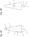
- the one or more suction openings 7c of each filling connection 7 may be arranged substantially along a mid-section thereof. As shown in Fig. 3a and 3b , the one or more suction openings 7c may be arranged substantially midway/halfway the length of the filling connection 7, so that parts of the filling connection 7 below and above the one or more suction openings 7c experience a similar vacuum/negative or positive pressure between the inner wall of the filling channel 5 and the filling connection 7.
- the one or more suction openings 7c are arranged in a side face/surface of the filling connection 7, wherein, in a further embodiment, the side face/surface may be a tapered surface, e.g. a conical surface.
- Fig. 4 shows an embodiment of a support table 20 according to the present invention.
- the cultivation system may comprise a support table 20 provided with at least one upward extending support post 21 comprising an upper end having a filling connection 7 attached thereto.
- the support post 21 allows a cultivation pot 1 to be positioned on a filling connection 7 away from the support table 20, so that the cultivation pot 1 can be handled by an automated pick-and-place system more easily as there is less interference from the support table 20.
- an automated pick-and-place system may be an automated crate system, wherein a crate is used to lower and lift the cultivation pot 1 to and away from the support table 20, i.e. the filling connection 7.
- the upper end of the support post 21 may comprise a support base 22 arranged (directly) below the filling connection 7, e.g. at the connection inlet 7f, wherein the support base 22 is configured to support the cultivation pot 1 when in use.
- the cultivation pot 1 rests on the support base 22, which may then determine the insertion depth of the filling connection 7 into the filling channel 5 of the cultivation pot 1.
- the filling connection 7 may be arranged offset from a centre point of the support base 22, thereby allowing for a cultivation pot 1 which is provided with a filling channel 5 offset from the centre/middle of the cultivation pot 1.
- This embodiment allows full support of the bottom wall 4a of the cultivation pot 1 whilst allowing offset placement of the filling channel 5.
- the support post 21 may be provided with a weight sensor and/or optical sensor configured to determine the water weight and/or water level 9, respectively, in a cultivation pot 1 when in use.
- the weight and/or optical sensor may be arranged on the support base 22. This allows close monitoring of the amount of water in the cultivation pot 1 and based on the measurements the supply of water can be controlled.
- Fig. 4 also shows how the support table 20 allows managing and handling of a plurality of cultivation pots 1.
- the cultivation system may comprise the support table 20 which is then provided with an array arrangement of at least two upward extending spaced apart support posts 21 each of which comprises an upper end having a filling connection 7 attached thereto.
- the at least two support posts 21 then have different heights with respect to the support table 20.
- the two spaced apart support posts 21 have different heights so that interference between plants of two adjacent cultivation pots 1 is prevented. This improves growth and prevents tangling of adjacent plants which would make placement and/or removal of the at least two cultivation pots 1 difficult.
- each of the at least two support posts 21 may comprise a support base 22 which is arranged (directly) below the filling connection 7, e.g. at the connection inlet 7f, wherein each support base 22 is configured to support a cultivation pot 1 when in use.
- each cultivation pot 1 is positioned on a respective support base 22 when in use, so that each support base 22 determines the insertion depth of the filling connection 7 into the filling channel 5 of the cultivation pot 1 supported on the respective support base 22.
- each filling connection 7 is arranged offset from a centre point of the support base 22, which is arranged (directly) below the filling connection 7, e.g. at the connection inlet 7f. This allows full support of the bottom wall 4a of the cultivation pot 1 whilst allowing offset placement of the fillings channel 5.
- providing an offset filling channel 5 to a cultivation pot 1 allows for efficient use of the cultivation pot 1 for plant varieties that tend to grow much more in width rather than height.
- By arranging each filling connection 7 offset from the centre point of the support base 22 allows for offset placement of each filling channel 5 whilst providing stable support to the cultivation pot 1.
- each support post 21 is provided with a weight sensor and/or optical sensor configured to determine a water weight and/or a water level, respectively, in the cultivation pot 1 supported on the support post 21 when in use.
- a weight sensor and/or optical sensor may be arranged on the support base 22 in a further embodiment.
- a weight sensor may be arranged directly underneath the support base 22 for measuring the weight of a cultivation pot 1 positioned on the support base 22. It is also conceivable that in an alternative embodiment the weight sensor is arranged directly on top of the support base 22 and configured to directly engage a cultivation pot 1.
- the support table 20 may be provided with an array arrangement of any plurality of upward extending spaced apart support posts 21, each of which comprises an upper end having a filling connection 7 attached thereto.
- the array arrangement forms a staggered/alternating arrangement of spaced apart support posts 21 with respect to height.
- any plurality of cultivation pots 1 can be used whilst preventing interference between the plants grown therein.
- Such a staggered/alternating arrangement of cultivation pots 1 at different heights also facilitates automated removal and placement of the cultivation pots 1.
- a (square) staggered/alternating arrangement of spaced apart support posts 21 is depicted based on two different heights.
- an automated crate positioning system it is possible to first remove cultivation pots 1 at the highest position with respect to the support table 20. This would yield a crate carrying a "checkerboard pattern" of spaced apart cultivation pots 1, allowing further growth of the plants kept in the cultivation pots 1 as there is more space for growth there between.
- Another crate may then be used to remove the cultivation pots 1 at the lowest position with respect the support table 20. This also yields a crate carrying a "checkerboard pattern" of spaced apart cultivation pots 1 to enable further growth of the plants kept therein.
- Fig. 4 further shows that the support table 20 may be connected to a water source by means of a hose or tube 23, and wherein the support table 20 may be provided with an electronic module 24 for e.g. connection to weight and/or optical sensors, water and/or steam valves etc.
Landscapes
- Life Sciences & Earth Sciences (AREA)
- Environmental Sciences (AREA)
- Engineering & Computer Science (AREA)
- Water Supply & Treatment (AREA)
- Cultivation Receptacles Or Flower-Pots, Or Pots For Seedlings (AREA)
- Hydroponics (AREA)
Claims (15)
- Kultursystem zur Kultivierung von Pflanzen z.B. aus Samen, Sämlingen, Setzlingen usw., welche in oder auf Substratpfropfen (2) in Kulturtöpfen (1) angeordnet sind, die ein Teil des Kultursystems sind oder damit assoziiert sind, wobei die Kulturtöpfe mit einem Füllkanal versehen sind, der sich von einem Boden und/oder einer Seitenwand (4a bzw. b) des Kulturtopfs nach oben erstreckt, wobei der Füllkanal angeordnet ist, um mit einem Füllmodul (6) zusammenzuwirken, das ein Teil des Kultursystems ist oder damit zusammenwirkt und das eine oder mehrere Füllverbindungen (7) aufweist, wobei jede Füllverbindung angeordnet ist, um mit dem Füllkanal (5) eines Kulturtopfs zur Versorgung des assoziierten Kulturtopfs mit Wasser ein Eingriff zu gelangen, ferner umfassend Mittel zum Messen der tatsächlichen Wassermenge oder des tatsächlichen Wasserspiegels in jedem assoziierten Kulturtopf (1) und zum zusätzlichen Einfüllen von Wasser in Abhängigkeit davon.
- Kultursystem nach Anspruch 1, wobei jede der Füllverbindungen (7) einen verjüngten oberen Teil für einen kongruenten Eingriff innerhalb eines verjüngten unteren Teils des Füllkanals (5) umfasst.
- Kultursystem nach Anspruch 1, wobei jede der Füllverbindungen (7) eine verjüngte Form entlang ihrer gesamten Länge für einen kongruenten Eingriff innerhalb einer verjüngten Form entlang der gesamten Länge des Füllkanals (5) aufweist, wobei jede Füllverbindung (7) eine obere Wasseröffnung (7a) aufweist, die dafür ausgelegt ist, um sich über eine obere Öffnung des Füllkanals (5) hinaus zu erstrecken, wenn sich die Füllverbindung (7) durch den Füllkanal (5) erstreckt.
- Kultursystem nach Anspruch 3, wobei die obere Wasseröffnung (7a) jeder Füllverbindung (7) in einer Seitenfläche davon angeordnet ist.
- Kultursystem nach einem der Ansprüche 1 bis 4, wobei jede Füllverbindung (7) eine oder mehrere Saugöffnungen (7c) umfasst, die für einen Saugeingriff mit einer Innenwand des Füllkanals (5) ausgelegt ist oder sind.
- Kultursystem nach Anspruch 5, wobei die eine oder die mehreren Saugöffnungen (7c) jeder Füllverbindung (7) im Wesentlichen entlang einer Mittelsektion davon angeordnet ist oder sind.
- Kultursystem nach einem der Ansprüche 1 bis 6, wobei das Filtermodul (6) ferner einen [bakteriellen/viralen] Filter (12) für jede Füllverbindung (7) umfasst, und wobei der Filter (12) stromaufwärts von der Füllverbindung (7) angeordnet ist.
- Kultursystem nach einem der Ansprüche 1 bis 7, wobei das Filtermodul (6) ferner eine Dampfquelle (14) für jede Füllverbindung (7) umfasst.
- Kultursystem nach Anspruch 8, wenn von Anspruch 7 abhängig, wobei die Dampfquelle (14) stromaufwärts von dem Filter (12) angeordnet ist.
- Kultursystem nach einem der Ansprüche 1 bis 9, ferner umfassend einen Trägertisch (20), der mit einer Arrayanordnung von mindestens zwei sich nach oben erstreckenden beabstandeten Trägerpfosten (21) versehen ist, von denen jeder ein oberes Ende mit einer daran angebrachten Füllverbindung (7) umfasst, wobei die mindestens zwei Trägerpfosten (21) unterschiedliche Höhen in Bezug auf den Trägertisch (20) aufweisen.
- Kultursystem nach Anspruch 10, wobei das obere Ende jedes Trägerpfostens (21) eine Trägerbasis (22) umfasst, die unterhalb der Füllverbindung (7) angeordnet ist, wobei die Trägerbasis (22) dafür ausgelegt ist, um im Gebrauch einen Kulturtopf (1) zu tragen.
- Kultursystem nach Anspruch 11, wobei jede Füllverbindung (7) von einem zentralen Punkt der Trägerbasis (22) versetzt angeordnet ist, die unter der Füllverbindung (7) angeordnet ist.
- Kultursystem nach einem der Ansprüche 1 bis 12, wobei jeder Trägerpfosten (21) mit einem Gewichtssensor oder optischen Sensor versehen ist, der dafür ausgelegt ist, um im Gebrauch jeweils das Wassergewicht oder den Wasserspiegel in einem Kulturtopf (1) zu bestimmen.
- Kultursystem nach einem der Ansprüche 1 bis 13, wobei jeder der Kulturtöpfe (1) mit einer perforierten Folie versehen ist, die dafür ausgelegt ist, um im Gebrauch den Kulturtopf (1) abzudecken.
- Kultursystem nach einem der Ansprüche 1 bis 14, wobei die Kulturtöpfe (1) transparent sind.
Applications Claiming Priority (2)
| Application Number | Priority Date | Filing Date | Title |
|---|---|---|---|
| NL1042822A NL1042822B1 (nl) | 2018-04-16 | 2018-04-16 | Kweeksysteem omvattende kweekpotten voorzien van een zich vanuit een bodem- en/of zijwand omhoog uitstrekkend vulkanaal |
| PCT/NL2019/050101 WO2019203637A1 (en) | 2018-04-16 | 2019-02-15 | Cultivation system for cultivating plants |
Publications (3)
| Publication Number | Publication Date |
|---|---|
| EP3780945A1 EP3780945A1 (de) | 2021-02-24 |
| EP3780945C0 EP3780945C0 (de) | 2023-09-20 |
| EP3780945B1 true EP3780945B1 (de) | 2023-09-20 |
Family
ID=66092384
Family Applications (1)
| Application Number | Title | Priority Date | Filing Date |
|---|---|---|---|
| EP19716252.2A Active EP3780945B1 (de) | 2018-04-16 | 2019-02-15 | Kultivierungssystem für pflanzen |
Country Status (5)
| Country | Link |
|---|---|
| US (1) | US11700803B2 (de) |
| EP (1) | EP3780945B1 (de) |
| JP (1) | JP7337405B2 (de) |
| NL (1) | NL1042822B1 (de) |
| WO (1) | WO2019203637A1 (de) |
Families Citing this family (3)
| Publication number | Priority date | Publication date | Assignee | Title |
|---|---|---|---|---|
| KR102832611B1 (ko) * | 2019-09-11 | 2025-07-11 | 삼성전자주식회사 | 재배 시스템, 재배 박스 및 그 제어 방법 |
| NL2024336B1 (en) * | 2019-11-29 | 2021-08-31 | Own Greens Holding B V | Cultivation pot, container and method for growing plants |
| US20230180687A1 (en) * | 2020-05-05 | 2023-06-15 | Land Green And Technology Co., Ltd. | Method and system for capable of selecting optimal plant cultivation method |
Family Cites Families (26)
| Publication number | Priority date | Publication date | Assignee | Title |
|---|---|---|---|---|
| US774988A (en) * | 1904-05-31 | 1904-11-15 | Louis Maurer | Device for keeping flowers on graves alive. |
| US3274730A (en) * | 1964-05-08 | 1966-09-27 | Whirlpool Co | Underground gas diffusion system |
| JPH01274894A (ja) * | 1988-04-26 | 1989-11-02 | Sansui:Kk | 流水殺菌装置と培養液の流水殺菌装置 |
| US5272562A (en) | 1993-02-05 | 1993-12-21 | Minnesota Mining And Manufacturing Company | Cube-corner retroreflective articles |
| US20020020111A1 (en) * | 2000-08-03 | 2002-02-21 | Peretz Rosenberg | Liquid dispensing devices particularly useful for irrigating plants |
| CN2722605Y (zh) | 2004-07-28 | 2005-09-07 | 余志鹏 | 节水蓄水式花盆 |
| US20060207175A1 (en) * | 2005-03-18 | 2006-09-21 | Wu Shi F | Flowerpot |
| WO2006102797A1 (fr) * | 2005-04-01 | 2006-10-05 | Jun Zhu | Tuyau dote d’une valve destine a reguler l’eau, tete destinee a reguler l’eau et micro-irrigateur |
| WO2007136531A2 (en) * | 2006-05-18 | 2007-11-29 | Sargent Ronald J | Apparatus for monitoring and regulating soil moisture |
| US20080134576A1 (en) * | 2006-12-08 | 2008-06-12 | Melinda Merryweather | Tree watering device |
| CH700639A1 (de) * | 2009-03-20 | 2010-09-30 | Alfons Egloff | Halterung für Pflanzentöpfe. |
| TWM403889U (en) * | 2010-09-17 | 2011-05-21 | Zhe-Peng Lin | Water supply device of planting container |
| US9149005B2 (en) * | 2011-12-22 | 2015-10-06 | Rockwool International A/S | Plant growth system |
| US9516821B1 (en) * | 2013-06-18 | 2016-12-13 | WaterWell Planters, Inc. | Self-watering planter insert assembly |
| CN203708968U (zh) | 2013-07-31 | 2014-07-16 | 李小波 | 用于城市道旁或园林盆栽花的自动浇水装置 |
| JP5639701B1 (ja) | 2013-09-12 | 2014-12-10 | パナソニック株式会社 | 水耕栽培装置及び水耕栽培方法 |
| NL2012234C2 (en) | 2014-02-10 | 2015-08-17 | Vivi B V | Plant holder. |
| CN104172819B (zh) * | 2014-08-07 | 2016-09-14 | 姚忠元 | 绿化花盆和墙壁式绿化花架 |
| CN104429875B (zh) * | 2014-12-04 | 2016-08-24 | 重庆华宇园林有限公司 | 防滑式水培箱 |
| CN105052714A (zh) * | 2015-07-27 | 2015-11-18 | 苏州纽东精密制造科技有限公司 | 一种锥型水培植物容器 |
| US20170188528A1 (en) | 2016-01-05 | 2017-07-06 | Jeff Gordon | Self-Watering Planter |
| GB2550105A (en) | 2016-03-22 | 2017-11-15 | Growell Hydroponics And Plant Lighting Ltd | Plant container irrigation apparatus |
| CN106212223B (zh) * | 2016-09-13 | 2022-04-08 | 运城清海科技有限公司 | 植物葆青罐 |
| US11096349B2 (en) * | 2017-08-02 | 2021-08-24 | Insectergy, Llc | Cannabis farming systems and methods |
| US20180368343A1 (en) * | 2017-06-22 | 2018-12-27 | Greg O'Rourke | Sustainable Growing System and Method |
| CN109463174A (zh) * | 2018-12-25 | 2019-03-15 | 安徽泽生态建设有限公司 | 一种垂直绿化装置 |
-
2018
- 2018-04-16 NL NL1042822A patent/NL1042822B1/nl not_active IP Right Cessation
-
2019
- 2019-02-15 EP EP19716252.2A patent/EP3780945B1/de active Active
- 2019-02-15 US US17/047,093 patent/US11700803B2/en active Active
- 2019-02-15 JP JP2021506607A patent/JP7337405B2/ja active Active
- 2019-02-15 WO PCT/NL2019/050101 patent/WO2019203637A1/en not_active Ceased
Also Published As
| Publication number | Publication date |
|---|---|
| EP3780945C0 (de) | 2023-09-20 |
| EP3780945A1 (de) | 2021-02-24 |
| NL1042822B1 (nl) | 2019-10-23 |
| US11700803B2 (en) | 2023-07-18 |
| WO2019203637A1 (en) | 2019-10-24 |
| US20210144941A1 (en) | 2021-05-20 |
| JP7337405B2 (ja) | 2023-09-04 |
| JP2021521887A (ja) | 2021-08-30 |
Similar Documents
| Publication | Publication Date | Title |
|---|---|---|
| EP3780945B1 (de) | Kultivierungssystem für pflanzen | |
| US9629314B2 (en) | Holder for plants and a plant cultivation method | |
| KR101232644B1 (ko) | 수경 재배용 베드 | |
| CN111343860B (zh) | 水培栽培装置以及水培栽培方法 | |
| KR101961291B1 (ko) | 개량된 급수구조를 갖는 다단식 식물 재배장치 | |
| KR20140081651A (ko) | 저면관수용 포트 받침 | |
| KR102039379B1 (ko) | 식재가 용이한 저수조 멀티 화분 | |
| GB2334420A (en) | Plant cultivating method and apparatus | |
| CN104082117A (zh) | 一种简易高通量的实验室植物水培装置 | |
| CN211090894U (zh) | 一种园林景观用花苗育苗装置 | |
| KR102300685B1 (ko) | 식물재배용 물 공급장치 | |
| US20250063994A1 (en) | Plant cultivation container | |
| WO2018062987A1 (en) | Method and system for cultivating plant material | |
| KR101232643B1 (ko) | 수경 재배장치 | |
| KR101614197B1 (ko) | 데스크용 전자 화분 | |
| EP2835047B1 (de) | Integriertes modulares system zur saatkiemung, kultivierung, bepflanzung, düngung und pflanzenwartung | |
| KR102558057B1 (ko) | 고설 재배용 딸기화분 개별 분리 및 취출 기능을 갖는 화분거취대 | |
| KR20210016139A (ko) | 착탈식 습도센서를 갖는 화분 | |
| CN210298899U (zh) | 一种带水位调节结构的水培种植管道 | |
| CN212812965U (zh) | 一种可进行水旱轮作的盆栽装置 | |
| CN210226343U (zh) | 一种花苗培育用简易浇水装置 | |
| KR20220151516A (ko) | 육묘포트용 저면관수시스템 | |
| KR20200057996A (ko) | 상단에 식물재배가 가능한 식물재배장치 | |
| KR20170057992A (ko) | 절수형 토양 양액 재배 겸용 화분 | |
| CN220733692U (zh) | 一种园林树木幼苗培育装置 |
Legal Events
| Date | Code | Title | Description |
|---|---|---|---|
| STAA | Information on the status of an ep patent application or granted ep patent |
Free format text: STATUS: UNKNOWN |
|
| STAA | Information on the status of an ep patent application or granted ep patent |
Free format text: STATUS: THE INTERNATIONAL PUBLICATION HAS BEEN MADE |
|
| PUAI | Public reference made under article 153(3) epc to a published international application that has entered the european phase |
Free format text: ORIGINAL CODE: 0009012 |
|
| STAA | Information on the status of an ep patent application or granted ep patent |
Free format text: STATUS: REQUEST FOR EXAMINATION WAS MADE |
|
| 17P | Request for examination filed |
Effective date: 20201113 |
|
| AK | Designated contracting states |
Kind code of ref document: A1 Designated state(s): AL AT BE BG CH CY CZ DE DK EE ES FI FR GB GR HR HU IE IS IT LI LT LU LV MC MK MT NL NO PL PT RO RS SE SI SK SM TR |
|
| AX | Request for extension of the european patent |
Extension state: BA ME |
|
| DAV | Request for validation of the european patent (deleted) | ||
| DAX | Request for extension of the european patent (deleted) | ||
| GRAP | Despatch of communication of intention to grant a patent |
Free format text: ORIGINAL CODE: EPIDOSNIGR1 |
|
| STAA | Information on the status of an ep patent application or granted ep patent |
Free format text: STATUS: GRANT OF PATENT IS INTENDED |
|
| INTG | Intention to grant announced |
Effective date: 20230503 |
|
| GRAS | Grant fee paid |
Free format text: ORIGINAL CODE: EPIDOSNIGR3 |
|
| GRAA | (expected) grant |
Free format text: ORIGINAL CODE: 0009210 |
|
| STAA | Information on the status of an ep patent application or granted ep patent |
Free format text: STATUS: THE PATENT HAS BEEN GRANTED |
|
| AK | Designated contracting states |
Kind code of ref document: B1 Designated state(s): AL AT BE BG CH CY CZ DE DK EE ES FI FR GB GR HR HU IE IS IT LI LT LU LV MC MK MT NL NO PL PT RO RS SE SI SK SM TR |
|
| REG | Reference to a national code |
Ref country code: GB Ref legal event code: FG4D |
|
| REG | Reference to a national code |
Ref country code: CH Ref legal event code: EP |
|
| REG | Reference to a national code |
Ref country code: IE Ref legal event code: FG4D |
|
| REG | Reference to a national code |
Ref country code: DE Ref legal event code: R096 Ref document number: 602019037791 Country of ref document: DE |
|
| U01 | Request for unitary effect filed |
Effective date: 20231011 |
|
| U07 | Unitary effect registered |
Designated state(s): AT BE BG DE DK EE FI FR IT LT LU LV MT NL PT SE SI Effective date: 20231019 |
|
| PG25 | Lapsed in a contracting state [announced via postgrant information from national office to epo] |
Ref country code: GR Free format text: LAPSE BECAUSE OF FAILURE TO SUBMIT A TRANSLATION OF THE DESCRIPTION OR TO PAY THE FEE WITHIN THE PRESCRIBED TIME-LIMIT Effective date: 20231221 |
|
| PG25 | Lapsed in a contracting state [announced via postgrant information from national office to epo] |
Ref country code: RS Free format text: LAPSE BECAUSE OF FAILURE TO SUBMIT A TRANSLATION OF THE DESCRIPTION OR TO PAY THE FEE WITHIN THE PRESCRIBED TIME-LIMIT Effective date: 20230920 Ref country code: NO Free format text: LAPSE BECAUSE OF FAILURE TO SUBMIT A TRANSLATION OF THE DESCRIPTION OR TO PAY THE FEE WITHIN THE PRESCRIBED TIME-LIMIT Effective date: 20231220 Ref country code: HR Free format text: LAPSE BECAUSE OF FAILURE TO SUBMIT A TRANSLATION OF THE DESCRIPTION OR TO PAY THE FEE WITHIN THE PRESCRIBED TIME-LIMIT Effective date: 20230920 Ref country code: GR Free format text: LAPSE BECAUSE OF FAILURE TO SUBMIT A TRANSLATION OF THE DESCRIPTION OR TO PAY THE FEE WITHIN THE PRESCRIBED TIME-LIMIT Effective date: 20231221 |
|
| U20 | Renewal fee for the european patent with unitary effect paid |
Year of fee payment: 6 Effective date: 20240104 |
|
| PG25 | Lapsed in a contracting state [announced via postgrant information from national office to epo] |
Ref country code: IS Free format text: LAPSE BECAUSE OF FAILURE TO SUBMIT A TRANSLATION OF THE DESCRIPTION OR TO PAY THE FEE WITHIN THE PRESCRIBED TIME-LIMIT Effective date: 20240120 |
|
| PG25 | Lapsed in a contracting state [announced via postgrant information from national office to epo] |
Ref country code: ES Free format text: LAPSE BECAUSE OF FAILURE TO SUBMIT A TRANSLATION OF THE DESCRIPTION OR TO PAY THE FEE WITHIN THE PRESCRIBED TIME-LIMIT Effective date: 20230920 |
|
| PG25 | Lapsed in a contracting state [announced via postgrant information from national office to epo] |
Ref country code: SM Free format text: LAPSE BECAUSE OF FAILURE TO SUBMIT A TRANSLATION OF THE DESCRIPTION OR TO PAY THE FEE WITHIN THE PRESCRIBED TIME-LIMIT Effective date: 20230920 Ref country code: RO Free format text: LAPSE BECAUSE OF FAILURE TO SUBMIT A TRANSLATION OF THE DESCRIPTION OR TO PAY THE FEE WITHIN THE PRESCRIBED TIME-LIMIT Effective date: 20230920 Ref country code: IS Free format text: LAPSE BECAUSE OF FAILURE TO SUBMIT A TRANSLATION OF THE DESCRIPTION OR TO PAY THE FEE WITHIN THE PRESCRIBED TIME-LIMIT Effective date: 20240120 Ref country code: ES Free format text: LAPSE BECAUSE OF FAILURE TO SUBMIT A TRANSLATION OF THE DESCRIPTION OR TO PAY THE FEE WITHIN THE PRESCRIBED TIME-LIMIT Effective date: 20230920 Ref country code: CZ Free format text: LAPSE BECAUSE OF FAILURE TO SUBMIT A TRANSLATION OF THE DESCRIPTION OR TO PAY THE FEE WITHIN THE PRESCRIBED TIME-LIMIT Effective date: 20230920 Ref country code: SK Free format text: LAPSE BECAUSE OF FAILURE TO SUBMIT A TRANSLATION OF THE DESCRIPTION OR TO PAY THE FEE WITHIN THE PRESCRIBED TIME-LIMIT Effective date: 20230920 |
|
| PG25 | Lapsed in a contracting state [announced via postgrant information from national office to epo] |
Ref country code: PL Free format text: LAPSE BECAUSE OF FAILURE TO SUBMIT A TRANSLATION OF THE DESCRIPTION OR TO PAY THE FEE WITHIN THE PRESCRIBED TIME-LIMIT Effective date: 20230920 |
|
| REG | Reference to a national code |
Ref country code: DE Ref legal event code: R097 Ref document number: 602019037791 Country of ref document: DE |
|
| PLBE | No opposition filed within time limit |
Free format text: ORIGINAL CODE: 0009261 |
|
| STAA | Information on the status of an ep patent application or granted ep patent |
Free format text: STATUS: NO OPPOSITION FILED WITHIN TIME LIMIT |
|
| 26N | No opposition filed |
Effective date: 20240621 |
|
| PG25 | Lapsed in a contracting state [announced via postgrant information from national office to epo] |
Ref country code: MC Free format text: LAPSE BECAUSE OF FAILURE TO SUBMIT A TRANSLATION OF THE DESCRIPTION OR TO PAY THE FEE WITHIN THE PRESCRIBED TIME-LIMIT Effective date: 20230920 |
|
| REG | Reference to a national code |
Ref country code: CH Ref legal event code: PL |
|
| PG25 | Lapsed in a contracting state [announced via postgrant information from national office to epo] |
Ref country code: CH Free format text: LAPSE BECAUSE OF NON-PAYMENT OF DUE FEES Effective date: 20240229 |
|
| PG25 | Lapsed in a contracting state [announced via postgrant information from national office to epo] |
Ref country code: CH Free format text: LAPSE BECAUSE OF NON-PAYMENT OF DUE FEES Effective date: 20240229 |
|
| PG25 | Lapsed in a contracting state [announced via postgrant information from national office to epo] |
Ref country code: IE Free format text: LAPSE BECAUSE OF NON-PAYMENT OF DUE FEES Effective date: 20240215 |
|
| PG25 | Lapsed in a contracting state [announced via postgrant information from national office to epo] |
Ref country code: IE Free format text: LAPSE BECAUSE OF NON-PAYMENT OF DUE FEES Effective date: 20240215 |
|
| U21 | Renewal fee for the european patent with unitary effect paid with additional fee |
Year of fee payment: 7 Effective date: 20250409 |
|
| PG25 | Lapsed in a contracting state [announced via postgrant information from national office to epo] |
Ref country code: CY Free format text: LAPSE BECAUSE OF FAILURE TO SUBMIT A TRANSLATION OF THE DESCRIPTION OR TO PAY THE FEE WITHIN THE PRESCRIBED TIME-LIMIT; INVALID AB INITIO Effective date: 20190215 |
|
| PG25 | Lapsed in a contracting state [announced via postgrant information from national office to epo] |
Ref country code: HU Free format text: LAPSE BECAUSE OF FAILURE TO SUBMIT A TRANSLATION OF THE DESCRIPTION OR TO PAY THE FEE WITHIN THE PRESCRIBED TIME-LIMIT; INVALID AB INITIO Effective date: 20190215 |
|
| PG25 | Lapsed in a contracting state [announced via postgrant information from national office to epo] |
Ref country code: TR Free format text: LAPSE BECAUSE OF FAILURE TO SUBMIT A TRANSLATION OF THE DESCRIPTION OR TO PAY THE FEE WITHIN THE PRESCRIBED TIME-LIMIT Effective date: 20230920 |
|
| U20 | Renewal fee for the european patent with unitary effect paid |
Year of fee payment: 8 Effective date: 20260224 |
|
| PGFP | Annual fee paid to national office [announced via postgrant information from national office to epo] |
Ref country code: GB Payment date: 20260223 Year of fee payment: 8 |