EP3780610A1 - Procédé, appareil et dispositif de commande de débit de code de codage de vidéo, et support de stockage - Google Patents
Procédé, appareil et dispositif de commande de débit de code de codage de vidéo, et support de stockage Download PDFInfo
- Publication number
- EP3780610A1 EP3780610A1 EP19775531.7A EP19775531A EP3780610A1 EP 3780610 A1 EP3780610 A1 EP 3780610A1 EP 19775531 A EP19775531 A EP 19775531A EP 3780610 A1 EP3780610 A1 EP 3780610A1
- Authority
- EP
- European Patent Office
- Prior art keywords
- picture frame
- domain complexity
- quantization parameter
- target bit
- space domain
- Prior art date
- Legal status (The legal status is an assumption and is not a legal conclusion. Google has not performed a legal analysis and makes no representation as to the accuracy of the status listed.)
- Pending
Links
Images


Classifications
-
- H—ELECTRICITY
- H04—ELECTRIC COMMUNICATION TECHNIQUE
- H04N—PICTORIAL COMMUNICATION, e.g. TELEVISION
- H04N19/00—Methods or arrangements for coding, decoding, compressing or decompressing digital video signals
- H04N19/10—Methods or arrangements for coding, decoding, compressing or decompressing digital video signals using adaptive coding
- H04N19/134—Methods or arrangements for coding, decoding, compressing or decompressing digital video signals using adaptive coding characterised by the element, parameter or criterion affecting or controlling the adaptive coding
- H04N19/146—Data rate or code amount at the encoder output
-
- H—ELECTRICITY
- H04—ELECTRIC COMMUNICATION TECHNIQUE
- H04N—PICTORIAL COMMUNICATION, e.g. TELEVISION
- H04N19/00—Methods or arrangements for coding, decoding, compressing or decompressing digital video signals
- H04N19/10—Methods or arrangements for coding, decoding, compressing or decompressing digital video signals using adaptive coding
- H04N19/134—Methods or arrangements for coding, decoding, compressing or decompressing digital video signals using adaptive coding characterised by the element, parameter or criterion affecting or controlling the adaptive coding
- H04N19/136—Incoming video signal characteristics or properties
- H04N19/137—Motion inside a coding unit, e.g. average field, frame or block difference
-
- H—ELECTRICITY
- H04—ELECTRIC COMMUNICATION TECHNIQUE
- H04N—PICTORIAL COMMUNICATION, e.g. TELEVISION
- H04N19/00—Methods or arrangements for coding, decoding, compressing or decompressing digital video signals
- H04N19/10—Methods or arrangements for coding, decoding, compressing or decompressing digital video signals using adaptive coding
- H04N19/102—Methods or arrangements for coding, decoding, compressing or decompressing digital video signals using adaptive coding characterised by the element, parameter or selection affected or controlled by the adaptive coding
- H04N19/124—Quantisation
-
- H—ELECTRICITY
- H04—ELECTRIC COMMUNICATION TECHNIQUE
- H04N—PICTORIAL COMMUNICATION, e.g. TELEVISION
- H04N19/00—Methods or arrangements for coding, decoding, compressing or decompressing digital video signals
- H04N19/10—Methods or arrangements for coding, decoding, compressing or decompressing digital video signals using adaptive coding
- H04N19/134—Methods or arrangements for coding, decoding, compressing or decompressing digital video signals using adaptive coding characterised by the element, parameter or criterion affecting or controlling the adaptive coding
- H04N19/136—Incoming video signal characteristics or properties
- H04N19/14—Coding unit complexity, e.g. amount of activity or edge presence estimation
-
- H—ELECTRICITY
- H04—ELECTRIC COMMUNICATION TECHNIQUE
- H04N—PICTORIAL COMMUNICATION, e.g. TELEVISION
- H04N19/00—Methods or arrangements for coding, decoding, compressing or decompressing digital video signals
- H04N19/10—Methods or arrangements for coding, decoding, compressing or decompressing digital video signals using adaptive coding
- H04N19/134—Methods or arrangements for coding, decoding, compressing or decompressing digital video signals using adaptive coding characterised by the element, parameter or criterion affecting or controlling the adaptive coding
- H04N19/157—Assigned coding mode, i.e. the coding mode being predefined or preselected to be further used for selection of another element or parameter
- H04N19/159—Prediction type, e.g. intra-frame, inter-frame or bidirectional frame prediction
-
- H—ELECTRICITY
- H04—ELECTRIC COMMUNICATION TECHNIQUE
- H04N—PICTORIAL COMMUNICATION, e.g. TELEVISION
- H04N19/00—Methods or arrangements for coding, decoding, compressing or decompressing digital video signals
- H04N19/10—Methods or arrangements for coding, decoding, compressing or decompressing digital video signals using adaptive coding
- H04N19/169—Methods or arrangements for coding, decoding, compressing or decompressing digital video signals using adaptive coding characterised by the coding unit, i.e. the structural portion or semantic portion of the video signal being the object or the subject of the adaptive coding
- H04N19/17—Methods or arrangements for coding, decoding, compressing or decompressing digital video signals using adaptive coding characterised by the coding unit, i.e. the structural portion or semantic portion of the video signal being the object or the subject of the adaptive coding the unit being an image region, e.g. an object
- H04N19/172—Methods or arrangements for coding, decoding, compressing or decompressing digital video signals using adaptive coding characterised by the coding unit, i.e. the structural portion or semantic portion of the video signal being the object or the subject of the adaptive coding the unit being an image region, e.g. an object the region being a picture, frame or field
-
- H—ELECTRICITY
- H04—ELECTRIC COMMUNICATION TECHNIQUE
- H04N—PICTORIAL COMMUNICATION, e.g. TELEVISION
- H04N19/00—Methods or arrangements for coding, decoding, compressing or decompressing digital video signals
- H04N19/85—Methods or arrangements for coding, decoding, compressing or decompressing digital video signals using pre-processing or post-processing specially adapted for video compression
- H04N19/86—Methods or arrangements for coding, decoding, compressing or decompressing digital video signals using pre-processing or post-processing specially adapted for video compression involving reduction of coding artifacts, e.g. of blockiness
-
- H—ELECTRICITY
- H04—ELECTRIC COMMUNICATION TECHNIQUE
- H04N—PICTORIAL COMMUNICATION, e.g. TELEVISION
- H04N19/00—Methods or arrangements for coding, decoding, compressing or decompressing digital video signals
- H04N19/10—Methods or arrangements for coding, decoding, compressing or decompressing digital video signals using adaptive coding
- H04N19/134—Methods or arrangements for coding, decoding, compressing or decompressing digital video signals using adaptive coding characterised by the element, parameter or criterion affecting or controlling the adaptive coding
- H04N19/146—Data rate or code amount at the encoder output
- H04N19/147—Data rate or code amount at the encoder output according to rate distortion criteria
-
- H—ELECTRICITY
- H04—ELECTRIC COMMUNICATION TECHNIQUE
- H04N—PICTORIAL COMMUNICATION, e.g. TELEVISION
- H04N19/00—Methods or arrangements for coding, decoding, compressing or decompressing digital video signals
- H04N19/10—Methods or arrangements for coding, decoding, compressing or decompressing digital video signals using adaptive coding
- H04N19/169—Methods or arrangements for coding, decoding, compressing or decompressing digital video signals using adaptive coding characterised by the coding unit, i.e. the structural portion or semantic portion of the video signal being the object or the subject of the adaptive coding
- H04N19/184—Methods or arrangements for coding, decoding, compressing or decompressing digital video signals using adaptive coding characterised by the coding unit, i.e. the structural portion or semantic portion of the video signal being the object or the subject of the adaptive coding the unit being bits, e.g. of the compressed video stream
-
- H—ELECTRICITY
- H04—ELECTRIC COMMUNICATION TECHNIQUE
- H04N—PICTORIAL COMMUNICATION, e.g. TELEVISION
- H04N19/00—Methods or arrangements for coding, decoding, compressing or decompressing digital video signals
- H04N19/50—Methods or arrangements for coding, decoding, compressing or decompressing digital video signals using predictive coding
- H04N19/503—Methods or arrangements for coding, decoding, compressing or decompressing digital video signals using predictive coding involving temporal prediction
-
- H—ELECTRICITY
- H04—ELECTRIC COMMUNICATION TECHNIQUE
- H04N—PICTORIAL COMMUNICATION, e.g. TELEVISION
- H04N19/00—Methods or arrangements for coding, decoding, compressing or decompressing digital video signals
- H04N19/50—Methods or arrangements for coding, decoding, compressing or decompressing digital video signals using predictive coding
- H04N19/593—Methods or arrangements for coding, decoding, compressing or decompressing digital video signals using predictive coding involving spatial prediction techniques
Definitions
- This disclosure relates to the field of picture processing technologies, and in particular, to a video encoding code rate control method, apparatus, and device, and a storage medium.
- Code rate control as an important component of video encoding, can optimize allocation of current remaining target bits according to a state of a channel, and dynamically adjust quantization parameters according to a current condition of an encoder, so as to provide optimal video quality under a limited bandwidth condition.
- a technical section of the code rate control is mainly divided into bit allocation and bit control.
- the bit allocation includes three phases: group of pictures (GOP)-level bit allocation, frame-level bit allocation and macroblock-level bit allocation.
- GOP group of pictures
- a target quantity of bits of the current GOP is allocated according to a bandwidth of a current channel, a frame rate of a current video and a length of the GOP.
- target bits of the current picture frame are allocated according to a quantity of remaining frames and a quantity of remaining bits in the current GOP.
- macroblocks in the current picture frame are encoded, the target bits are allocated to a currently encoding unit according to remaining bit data in the current picture frame and a quantity of macroblocks to be encoded.
- bit allocation when bit allocation is performed at a frame level, for the quantity of remaining bits of the current GOP, two modes are mainly used: average allocation and bit allocation according to predetermined weights.
- This distribution mode can achieve a desirable effect in a continuous natural scene.
- a user may experience a series of complex operations such as mobile phone shaking, light changing, scene transitions or camera switching. Therefore, diversified video call scenes may occur.
- bit allocation and quantization parameter calculation solution cannot make an adaptive adjustment according to a change of video content, resulting in a large amount of bits consumed by the current picture frame and causing a relatively long time delay or a video freezing phenomenon, which affects user experience.
- An embodiment of this disclosure provides a video encoding code rate control method, including:
- An embodiment of this disclosure provides a video encoding code rate control method, including:
- An embodiment of this disclosure further provides a video encoding code rate control apparatus, including:
- An embodiment of this disclosure further provides a video encoding code rate control device, including a processor and a memory, the memory storing at least one instruction, at least one program, a code set, or an instruction set, and the at least one instruction, the at least one program, the code set or the instruction set being loaded and executed by the processor to implement the video encoding code rate control method according to the embodiment of this disclosure.
- An embodiment of this disclosure provides a computer-readable storage medium, the storage medium storing at least one instruction, at least one program, a code set, or an instruction set, and the at least one instruction, the at least one program, the code set or the instruction set being loaded and executed by a processor to implement the video encoding code rate control method according to the embodiment of this disclosure.
- FIG. 1A is a system architecture diagram applicable to a video encoding code rate control method according to an embodiment of this disclosure.
- the system architecture diagram applicable to the video encoding code rate control method according to some embodiments of this disclosure at least includes: a first terminal 11, a network 12, and a server 13.
- the system architecture diagram applicable to the video encoding code rate control method according to some embodiments of this disclosure may further include: a second terminal 14.
- the first terminal 11 and the second terminal 14 may refer to intelligent devices having a data computing and processing function, and include but are not limited to a smartphone, a palmtop computer, a tablet computer, a personal computer, and the like (in which a communications module is installed).
- An operating system is installed on the device terminal 11, including but not limited to: an Android operating system, a Symbian operating system, a Windows mobile operating system, an Apple iPhone OS operating system, and the like.
- the first terminal 11 and the second terminal 14 are provided with various disclosure clients such as an disclosure client for video encoding code rate control.
- the network 12 may include a wired network and a wireless network. As shown in FIG. 1A , on a side of an access network, the first terminal 11 and the second terminal 14 may access the network 12 in a wireless or wired manner. However, on a side of a core network, the server 13 is usually connected to the network 12 in a wired manner. The server 13 may alternatively be connected to the network 12 in a wireless manner.
- the server 13 may be a server of an disclosure client, and is mainly configured to receive a compressed code stream transmitted by a terminal device.
- the server 13 may be an independent server, or may be a cluster server including a plurality of servers.
- an embodiment of this disclosure provides a video encoding code rate control method executed by a terminal device.
- the terminal device may be a first terminal, or may be a second terminal.
- the method may include the following steps.
- step S101 video information is captured by using a corresponding picture capture device (e.g., a camera) of a current mobile terminal. Specifically, picture frames in a video to be transmitted are obtained, and a picture frame to be transmitted is used as a first picture frame (a current picture frame), which serves as an object of subsequent processing.
- a corresponding picture capture device e.g., a camera
- a frame is a single image picture of a minimum unit in a video, a single frame is a still picture, and continuous frames form an animation, a video, or the like.
- the quantity of frames in short, is the quantity of frames of pictures transmitted in one second, which may also be interpreted as the number of refreshes per second of a graphics processor, and may be generally represented by frames per second (FPS).
- FPS frames per second
- Each frame is a still picture, and frames displayed quickly and continuously produce a motion illusion.
- a smooth and vivid animation may be obtained with a high frame rate. As FPS increases, a displayed action is smoother.
- the first picture frame is processed to obtain a space domain complexity of the first picture frame and a time domain complexity of the first picture frame.
- the processing of the first picture frame may include: downsampling a video picture, and then calculating a space domain complexity and a time domain complexity of the downsampled picture by using an 8 * 8 pixel block as a basic unit.
- Each pixel block may be referred to as one basic unit.
- a reference frame in the encoding process mainly adopts an intra picture and predicted picture (IPPP) format structure.
- IPPP is an encoding structure, in which only P frames exist and the current frame may only refer to a forward frame, as shown in FIG. 2 .
- the space domain complexity of the first picture frame is used for representing a texture complexity of the first picture frame.
- a scene with higher space complexity indicates a higher value of the space domain complexity.
- the space domain complexity corresponds to intra-frame prediction.
- the intra-frame prediction is prediction based on an encoded block in the same frame, to construct a prediction block and calculate a residual with the current block, thereby encoding information such as the residual and the prediction mode.
- the intra-frame prediction is mainly to remove spatial redundancy.
- the time domain complexity of the first picture frame is a time domain correlation between the first picture frame and an encoded picture frame in a group of pictures in which the first picture frame is located, and is used for representing a time variation of a picture frame sequence.
- the picture frame sequence having a relatively high motion degree usually has a relatively high time domain complexity value.
- the time domain complexity corresponds to inter-frame prediction.
- the inter-frame prediction is prediction based on one or more encoded frames, to construct a prediction block and calculate a residual with the current block, thereby encoding information such as the residual, the prediction mode, a motion vector residual, and a reference picture index.
- the inter-frame prediction is mainly to remove temporal redundancy.
- a first target bit of the first picture frame is updated to a second target bit according to the space domain complexity and the time domain complexity.
- a first initial quantization parameter of the first picture frame is updated to a second initial quantization parameter according to the space domain complexity and the time domain complexity.
- the first target bit is an existing target bit
- the first initial quantization parameter is an existing initial quantization parameter
- the second target bit is a new target bit
- the second initial quantization parameter is a new initial quantization parameter
- the existing target bit is a target bit allocated, after an encoder of the terminal device allocates a target bit quantity to the group of pictures in which the first picture frame is located, to the first picture frame according to a remaining frame quantity and a remaining bit quantity in the current group of pictures during encoding of the first picture frame.
- the existing initial quantization parameter is a quantization parameter obtained through calculation according to the existing target bit of the first picture frame.
- step S102 the updating a first target bit of the first picture frame to a second target bit according to the space domain complexity and the time domain complexity can include the following steps.
- a motion estimation attribute of the first picture frame and a motion estimation attribute of a second picture frame are obtained, the motion estimation attribute of the first picture frame being a ratio of the space domain complexity to the time domain complexity of the first picture frame, the motion estimation attribute of the second picture frame being a ratio of the time domain complexity to the space domain complexity of the second picture frame, and the second picture frame being a previous picture frame of the first picture frame.
- a first limiting condition is obtained, and the first target bit of the first picture frame is adjusted to the second target bit according to the first limiting condition, the first limiting condition including a ratio of the motion estimation attribute of the first picture frame to the motion estimation attribute of the second picture frame.
- step S 102 the updating a first initial quantization parameter of the first picture frame to a second initial quantization parameter according to the space domain complexity and the time domain complexity includes: obtaining a second limiting condition, and updating the first initial quantization parameter of the first picture frame to the second initial quantization parameter according to the second limiting condition, the second limiting condition including a ratio of the space domain complexity of the first picture frame to a space domain complexity of a second picture frame, and a ratio of the space domain complexity of the first picture frame to a space domain complexity of a previous picture frame of the second picture frame.
- bit control is performed by using a quadratic rate-distortion model.
- a formula corresponding to the quadratic rate-distortion model is shown in formula (1):
- R ⁇ R Head M a ⁇ QP ⁇ 1 + b ⁇ QP ⁇ 2
- R Head is the quantity of bits consumed for header information of the macroblock
- M is a mean absolute difference (MAD) of a residual signal of the first picture frame (the current picture frame)
- a and b are corresponding limiting parameters.
- the MAD is obtained by updating formula (2):
- MAD j p 1 ⁇ MAD j ⁇ 1 + p 2
- MAD ( j -1) represents an actual MAD value of a previous frame of the current picture frame
- p1 and p2 are corresponding limiting parameters.
- a compressed code stream of the first picture frame is generated according to the second target bit and the second initial quantization parameter.
- the code stream refers to data traffic used by a video file per unit time, and is the most important part of picture quality control in video encoding.
- the existing target bit and the initial quantization parameter are adjusted to adapt to scene switching, so as to obtain a video stream suitable for transmission, namely, a compressed code stream.
- the target bit quantity and the encoding quantization parameter of the first picture frame are adjusted, thereby effectively reducing a peak code rate per second when a scene is switched or a scene is moved, and avoiding code rate runaway, so that the video stream can be smoothly transmitted.
- An embodiment of this disclosure further provides another video encoding code rate control method. As shown in FIG. 4 , the method can include the following steps.
- a video picture is downsampled, and then a space domain complexity Icost and a time domain complexity Pcost of the downsampled picture are calculated by using an 8 ⁇ 8 pixel block as a basic unit.
- Each pixel block may be regarded as one basic unit.
- the basic unit may be equal to the foregoing macroblock.
- the obtaining a space domain complexity of a first picture frame in a video stream includes: obtaining an optimal intra-frame prediction cost of a first basic unit in the first picture frame; and obtaining the space domain complexity of the first picture frame according to the optimal intra-frame prediction cost of the first basic unit.
- the optimal intra-frame prediction cost is a calculated estimated quantity of bits consumed by the first picture frame.
- the amount of distortion of the first picture frame may also be considered. That is, the optimal intra-frame prediction cost may also be a weighted sum of the quantity of estimated bits consumed by the first picture frame and the amount of distortion of the first picture frame.
- the method specifically includes the following steps:
- step S2A a plurality of target directions is selected from intra-frame prediction directions of the first picture frame, at intervals of a first preset quantity of intra-frame prediction directions. An intra-frame cost of each target direction is obtained.
- step S2B a target direction corresponding to a minimum intra-frame cost is used as an optimal direction.
- step S2C an optimal intra-frame prediction direction is obtained by using the optimal direction as a center and a second preset quantity as a radius.
- step S2C in some embodiments, the second preset quantity is half of the first preset quantity.
- the optimal intra-frame prediction direction is obtained by using the optimal direction as the center and 8/2 as the radius. That is, with the optimal direction as the center, four basic units are searched for on the left side and the right side respectively to obtain the optimal intra-frame prediction direction.
- step S2D a sum of absolute transformed differences (SATD) value of a residual between the first basic unit and a second basic unit is obtained, based on the optimal intra-frame prediction direction, to obtain an optimal intra-frame prediction cost of the first basic unit.
- the space domain complexity of the first picture frame is calculated according to the optimal intra-frame prediction cost of the first basic unit.
- the second basic unit is a basic unit in the optimal intra-frame prediction direction.
- the SATD is a measure of a size of a video residual signal, and the value of the SATD is obtained by performing a Hadamard transform on a corresponding residual and then summing absolute values. In a video coding standard, the Hadamard transform is mostly used for calculating the SATD.
- a picture frame having 35 intra-frame directions is used as an example.
- the optimal intra-frame prediction direction of the first basic unit is obtained first.
- the optimal intra-frame prediction direction is obtained in two stages: First, the intra-frame cost is calculated by taking one direction from the 35 intra-frame prediction directions at intervals of ⁇ directions, and after primary screening in this mode, the optimal direction is obtained. In the second phase, the optimal direction is used as a center to search for an optimal intra-frame prediction direction within a radius of ⁇ /2.
- a value of ⁇ being 8 is used as an example.
- the SATD value of the residual between the first basic unit and the second basic unit is calculated to obtain the optimal intra-frame prediction cost of the first basic unit.
- the optimal intra-frame prediction cost of the first picture frame that is, the space domain complexity of the first picture frame is calculated according to the optimal intra-frame prediction cost of the first basic unit.
- the space domain complexity Icost of the first picture frame is represented by ⁇ I _ cur ' and the space domain complexity Icost of the second picture frame is represented by ⁇ I _ pre .
- the obtaining a time domain complexity of the first picture frame includes: obtaining an optimal inter-frame prediction cost of a first basic unit in the first picture frame; and obtaining the time domain complexity of the first picture frame according to the optimal inter-frame prediction cost of the first basic unit.
- the method specifically includes the following steps:
- step S2a an optimum matching block of the first basic unit in the first picture frame is obtained by using a positive pixel diamond search algorithm, and the optimum matching block is used as a reference unit.
- step S2b an SATD value of a residual between the reference unit and the first basic unit is obtained, the SATD value being an optimal cost of the first basic unit.
- the obtaining a time domain complexity of the first picture frame further includes the following step:
- step S2c in which the optimal cost of the first basic unit is compared with an optimal intra-frame prediction cost of the first basic unit, a minimum value is used as an optimal inter-frame prediction cost of the first basic unit.
- the time domain complexity of the first picture frame is obtained according to the optimal inter-frame prediction cost of the first basic unit.
- an optimal best matching block of the first basic unit is obtained by using a positive pixel diamond search algorithm, and the best matching block is used as a reference unit. After the reference unit is determined, the SATD value of the residual is further calculated as the optimal cost of the first basic unit. Finally, the obtained optimal cost is compared with Icost of the first basic unit, and a minimum value is used as Pcost of the first basic unit. Pcost of the first picture frame is further obtained. Pcost of the first picture frame is represented by ⁇ P _ cur , and Pcost of the previous frame of the first picture frame is represented by ⁇ P_pre .
- step S202a a first target bit of the first picture frame is updated to a second target bit according to the space domain complexity and the time domain complexity; as shown in FIG. 7 , this step includes the following steps.
- step S3A the first target bit of the first picture frame is adjusted by using a first bit adjustment function to obtain the second target bit of the first picture frame in a case that a motion estimation attribute of the first picture frame is less than a first section parameter; or
- step S3B the first target bit of the first picture frame is adjusted by using a second bit adjustment function to obtain the second target bit of the first picture frame in a case that the motion estimation attribute of the first picture frame is less than a second section parameter; or
- step S3C the first target bit of the first picture frame is adjusted by using a third bit adjustment function to obtain the second target bit of the first picture frame in a case that the motion estimation attribute of the first picture frame is less than a third section parameter.
- Values of the first section parameter, the second section parameter, and the third section parameter belong to a same trend, and sequentially increase in this embodiment.
- the first picture frame is a current picture frame
- the second picture frame is a previous picture frame of the current picture frame, that is, a last picture frame of the current picture frame.
- the ratio of the time domain complexity ⁇ I_cur to the space domain complexity ⁇ P_cur corresponding to the first picture frame is used as the motion estimation attribute ⁇ IP_ cur of the first picture frame.
- the ratio of the time domain complexity ⁇ I_ pre to the space domain complexity ⁇ P _pre corresponding to the second picture frame is used as the motion estimation attribute ⁇ IP _ pre of the second picture frame.
- the ratio of the motion estimation attribute ⁇ IP_ cur of the first picture frame and the ratio of the motion estimation attribute ⁇ IP_pre of the second picture frame is used as a limiting condition to adjust the first target bit R T ar of the first picture frame, to obtain the second target bit R T ar ' of the first picture frame.
- the adjusting the first target bit R T ar of the first picture frame to obtain the second target bit R T ar ' of the first picture frame includes: after the target bit R T ar is obtained according to an existing calculation mode of the target bit, setting a piecewise function according to the time and space domain complexities of a first picture, and setting three grades ⁇ 1 , ⁇ 2 and ⁇ 3 according to the value of ⁇ IP_ cur , to adjust R T ar .
- ⁇ 1 , ⁇ 2 and ⁇ 3 are set to 2.5, 3, 3.5 respectively in this embodiment.
- R T ar ′ ⁇ ⁇ 1 ⁇ R T ar ⁇ IP _ pre / ⁇ IP _ cur ⁇ ⁇ 1 ⁇ 2 ⁇ R T ar ⁇ 2 ⁇ ⁇ IP _ pre / ⁇ IP _ cur ⁇ ⁇ 1 ⁇ 3 ⁇ R T ar ⁇ 3 ⁇ ⁇ IP _ pre / ⁇ IP _ cur ⁇ ⁇ 2
- ⁇ 1 , ⁇ 2 and ⁇ 3 are weights for adjusting R T ar according to the time and space domain complexities of the picture; ⁇ 1 , ⁇ 2 and ⁇ 3 are a first condition parameter, a second condition parameter and a third condition parameter respectively.
- ⁇ 1 , ⁇ 2 and ⁇ 3 are set to 3.2, 2.6 and 1.6 respectively, and ⁇ 1 , ⁇ 2 and ⁇ 3 are set to 3, 2.5, and 2 respectively.
- the adjusting the first target bit R T ar of the first picture frame further includes: adjusting the first target bit R T ar of the first picture frame by using the following formula (a fourth bit adjustment function) to obtain the second target bit R T ar ' of the first picture frame:
- R T ar ′ ⁇ 4 ⁇ R T ar ⁇ P _ cur / ⁇ P _ pre > ⁇ 4
- ⁇ 4 is a fourth weight for adjusting R T ar , and ⁇ 4 is a fourth condition parameter. In the embodiment, ⁇ 4 is set to 2, and ⁇ 4 is set to 5.
- ⁇ 5 and ⁇ 6 are a fifth weight and a sixth weight for adjusting R T ar ; ⁇ 5 and ⁇ 6 are a fifth condition parameter and a sixth condition parameter respectively.
- ⁇ 5 and ⁇ 6 are set to 2.6 and 2
- ⁇ 5 and ⁇ 6 are set to 2 and 1.5.
- ⁇ 7 is a seventh weight for adjusting R T ar ; ⁇ 7 is a seventh conditional parameter. In this embodiment, ⁇ 7 is set to 2, and ⁇ 7 is set to 1.2.
- the corresponding piecewise function may further be adjusted according to a scene requirement.
- the first bit adjustment function corresponding to the case of ⁇ IP _cur ⁇ ⁇ 1 may be set to a piecewise function with four pieces; for data obtained by adjustment based on the piecewise function with four pieces, an effect finally displayed at a receiving end needs to be further tested and adjusted, and appropriate parameters are selected to meet the scene requirement.
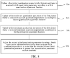
- step S202b a first initial quantization parameter of the first picture frame is updated to a second initial quantization parameter according to the space domain complexity and the time domain complexity. As shown in FIG. 8 , this step includes the following step:
- the method further includes the following steps:
- a step S3b in which a first maximum quantization parameter of the first picture frame is updated to a second maximum quantization parameter according to a second quantization adjustment function; and/or, a step S3c, in which a first minimum quantization parameter of the first picture frame is updated to a second minimum quantization parameter according to a third quantization adjustment function.
- the method further includes the following step:
- the first picture frame is a current picture frame
- the second picture frame is a previous picture frame, that is, a previous picture frame of the current picture frame.
- the ratio of the space domain complexity ⁇ P_ cur of the first picture frame to the space domain complexity ⁇ P _ pre of the second picture frame and the ratio of the space domain complexity ⁇ P _ cur of the first picture frame to the space domain complexity ⁇ P _ prepre of the previous picture frame of the second picture frame are used as a limiting condition.
- the first initial quantization parameter of the first picture frame QP frame is adjusted to obtain the second initial quantization parameter QP frame 1 of the first picture frame.
- the adjusting the first initial quantization parameter QP frame of the first picture frame to obtain QP frame 1 includes:
- the first maximum quantization parameter QP max of the first picture frame is adjusted by using the following formula (the second quantization adjustment function):
- QP max ′ ⁇ QP max + ⁇ 1 ⁇ P _ cur / ⁇ P _ pre > ⁇ 1 & ⁇ P _ cur / ⁇ P _ prepre > ⁇ 2
- the first minimum quantization parameter QP min of the first picture frame is adjusted by using the following formula (the third quantization adjustment function):
- QP min ′ ⁇ QP min + ⁇ 1 ⁇ P _ cur / ⁇ P _ pre > ⁇ 1 & ⁇ P _ cur / ⁇ P _ prepre > ⁇ 2
- whether the first picture frame is in a large-amplitude motion scene is determined according to a Pcost relationship between the first picture frame and the second picture frame, and a Pcost relationship between the first picture frame (the current picture frame) and a picture frame prior to the previous picture frame (that is, the picture frame prior to the second picture frame (the previous picture frame)). If the first picture frame is in the large-amplitude motion scene, the initial quantization parameter of the first picture frame needs to be up-regulated, to avoid consuming excessive bits during encoding.
- ⁇ P_pre and ⁇ P _prepre represent Pcost of the second picture frame and Pcost of the picture frame prior to the previous picture frame (that is, the picture frame prior to the second picture frame (the previous picture frame)) respectively.
- Both ⁇ 1 and ⁇ 3 are thresholds of a Pcost ratio between the first picture frame and the second picture frame (the previous picture frame).
- ⁇ 1 and ⁇ 3 are set to 6 and 3.
- Both ⁇ 2 and ⁇ 4 are thresholds of a Pcost ratio between the first picture frame and the picture frame prior to the second picture frame.
- ⁇ 2 and ⁇ 4 are set to 8 and 4.
- ⁇ 1 and ⁇ 2 are a first offset value and a second offset value corresponding to the current initial QP, the maximum QP and the minimum QP respectively.
- ⁇ 1 and ⁇ 2 are set to 6 and 3.
- the method further includes:
- step S203 a compressed code stream of the first picture frame is generated according to the second target bit and the second initial quantization parameter.
- the existing target bit is adjusted according to different fluctuation degrees of the first picture frame in different scenes, and the existing quantization parameters (the initial quantization parameter, the maximum quantization parameter and the minimum quantization parameter) are properly adjusted according to different time domain correlations between the first picture frame and the second picture frame in different scenes. That is, the picture parameters may be adaptively adjusted according to a content characteristic of the current picture, so that relatively few bits are consumed in the process of transmitting the first picture frame, and a long time delay or a video freezing phenomenon is avoided in the real-time video process, thereby improving user experience.
- An embodiment provides a video encoding code rate control method. As shown in FIG. 9 , the method includes the following steps:
- step S301 a first terminal obtains a first picture frame in a video stream.
- step S302 the first terminal processes the first picture frame to obtain a space domain complexity of the first picture frame and a time domain complexity of the first picture frame.
- step S303 the first terminal updates a first target bit of the first picture frame to a second target bit according to the space domain complexity and the time domain complexity, and updates a first initial quantization parameter of the first picture frame to a second initial quantization parameter.
- step S304 the first terminal generates a compressed code stream of the first picture frame according to the second target bit and the initial quantization parameter.
- step S305 the first terminal transmits the compressed code stream to a server.
- a second mobile terminal obtains the compressed code stream from the server, decodes the compressed code stream, and displays, on the second mobile terminal, a target picture frame obtained through decoding.
- the first terminal before transmitting video data, the first terminal first adjusts parameters of a picture frame to be transmitted, to obtain a compressed code stream applicable to a requirement of a scene, so that fewer bits are consumed during the transmission of the video data and the video data can be transmitted smoothly, thereby improving user viscosity of a corresponding disclosure.
- An embodiment provides a video encoding code rate control apparatus. As shown in FIG. 10 , the apparatus includes:
- the apparatus in the apparatus embodiment can be based on the same concept as the method embodiment.
- An embodiment provides a video encoding code rate control apparatus.
- the apparatus includes: a time-space domain complexity obtaining module 210, configured to obtain a space domain complexity of a first picture frame, and obtain a time domain complexity of the first picture frame in a video stream.
- the time-space domain complexity obtaining module 210 includes a space domain complexity obtaining unit 211.
- the space domain complexity obtaining unit 211 includes:
- the space domain complexity obtaining unit may include:
- time-space domain complexity obtaining module 210 includes a time domain complexity obtaining unit 212. As shown in FIG. 13 , the time domain complexity obtaining unit 212 includes:
- the time domain complexity obtaining unit may include:
- a parameter adjustment module 220 is configured to adjust a first target bit of the first picture frame according to the space domain complexity and the time domain complexity to obtain a second target bit of the first picture frame; and adjust a first initial quantization parameter of the first picture frame according to the space domain complexity and the time domain complexity to obtain a second initial quantization parameter of the first picture frame.
- the parameter adjustment module 220 includes:
- the second target bit obtaining unit 222 includes:
- the first section parameter, the second section parameter, and the third section parameter increase sequentially.
- the parameter adjustment module 220 includes: a second quantization parameter obtaining unit 223, configured to obtain a second limiting condition, and update the first initial quantization parameter of the first picture frame to the second initial quantization parameter according to the second limiting condition, the second limiting condition including a ratio of the space domain complexity of the first picture frame to a space domain complexity of a second picture frame, and a ratio of the space domain complexity of the first picture frame to a space domain complexity of a previous picture frame of the second picture frame.
- the second quantization parameter obtaining unit 223 includes: an initial quantization adjustment subunit 2231, configured to update the first initial quantization parameter of the first picture frame to the second initial quantization parameter according to a first quantization adjustment function.
- the second quantization parameter obtaining unit 232 further includes:
- the quantization parameter obtaining unit further includes:
- the apparatus in the apparatus embodiment can be based on the same concept as the method embodiment.
- An embodiment of this disclosure further provides a video encoding code rate control device, including a processor and a memory, the memory storing at least one instruction, at least one program, a code set, or an instruction set, and the at least one instruction, the at least one program, the code set or the instruction set being loaded and executed by the processor to implement the video encoding code rate control method according to the method embodiments.
- An embodiment of this disclosure provides a computer-readable storage medium, the storage medium storing at least one instruction, at least one program, a code set, or an instruction set, and the at least one instruction, the at least one program, the code set or the instruction set being loaded and executed by a processor to implement the video encoding code rate control method according to the method embodiments.
- the at least one instruction, the at least one program, the code set or the instruction set includes instructions used for performing the following operations:
- An embodiment of this disclosure further provides a video encoding code rate control device.
- the device may be configured to implement the video encoding code rate control method according to the foregoing embodiments. As shown in FIG. 17 , specifically:
- the device may include components such as a radio frequency (RF) circuit 810, a memory 820 including one or more computer-readable storage media, an input unit 830, a display unit 840, a sensor 850, an audio circuit 860, a wireless fidelity (WiFi) module 870, a processor 880 including one or more processing cores, and a power supply 890.
- RF radio frequency
- the RF circuit 810 may be configured to receive and transmit a signal during an information receiving and transmitting process or a call process. Specifically, the RF circuit receives downlink information from a base station, then delivers the downlink information to one or more processors 880 for processing, and transmits related uplink data to the base station.
- the RF circuit 810 includes, but is not limited to, an antenna, at least one amplifier, a tuner, one or more oscillators, a subscriber identity module (SIM) card, a transceiver, a coupler, a low noise amplifier (LNA), a duplexer, and the like.
- SIM subscriber identity module
- LNA low noise amplifier
- the RF circuit 810 may also communicate with a network and another device by wireless communication.
- the wireless communication may use any communications standard or protocol, including but not limited to a Global System for Mobile Communications (GSM), a general packet radio service (GPRS), Code Division Multiple Access (CDMA), Wideband Code Division Multiple Access (WCDMA), Long Term Evolution (LTE), an e-mail, a short message service (SMS), or the like.
- GSM Global System for Mobile Communications
- GPRS general packet radio service
- CDMA Code Division Multiple Access
- WCDMA Wideband Code Division Multiple Access
- LTE Long Term Evolution
- SMS short message service
- the memory 820 may be configured to store a software program and module.
- the processor 880 runs the software program and module stored in the memory 820, to implement various functional disclosures and data processing.
- the memory 820 may mainly include a program storage area and a data storage area.
- the program storage area may store an operating system, an disclosure program required by a function, and the like.
- the data storage area may store data created according to use of the device, and the like.
- the memory 820 may include a high-speed random access memory, and may also include a non-volatile memory, such as at least one magnetic disk storage device, a flash memory, or another volatile solid-state storage device.
- the memory 820 may further include a memory controller, so as to provide access of the processor 880 and the input unit 830 to the memory 820.
- the input unit 830 may be configured to: receive input digit or character information, and generate a keyboard, mouse, joystick, optical, or trackball signal input related to a user setting and function control.
- the input unit 830 may include a touch-sensitive surface 831 and another input device 832.
- the touch-sensitive surface 831 may also be referred to as a touch display screen or a touch panel, and may collect a touch operation of a user on or near the touch-sensitive surface (such as an operation of a user on or near the touch-sensitive surface 831 by using any suitable object or accessory, such as a finger or a stylus), and drive a corresponding connection apparatus according to a preset program.
- the touch-sensitive surface 831 may include two parts: a touch detection apparatus and a touch controller.
- the touch detection apparatus detects a touch position of the user, detects a signal generated by the touch operation, and transfers the signal to the touch controller.
- the touch controller receives the touch information from the touch detection apparatus, converts the touch information into touch point coordinates, and transmits the touch point coordinates to the processor 880.
- the touch controller can receive a command transmitted by the processor 880 and execute the command.
- the touch-sensitive surface 831 may be implemented by using various types, such as a resistive type, a capacitance type, an infrared type, and a surface sound wave type.
- the input unit 830 may further include another input device 832.
- the another input device 832 may include, but is not limited to, one or more of a physical keyboard, a functional key (e.g., a volume control key or a switch key), a trackball, a mouse, and a joystick.
- the display unit 840 may be configured to display information inputted by the user or information provided for the user, and various graphical user interfaces of the device.
- the graphical user interfaces may include a graph, a text, an icon, a video and any combination thereof.
- the display unit 840 may include a display panel 841.
- the display panel 841 may be configured by using a liquid crystal display (LCD), an organic light-emitting diode (OLED), or the like.
- the touch-sensitive surface 831 may cover the display panel 841. After detecting a touch operation on or near the touch-sensitive surface, the touch-sensitive surface 831 transfers the touch operation to the processor 880, so as to determine the type of the touch event.
- the processor 880 then provides a corresponding visual output on the display panel 841 according to the type of the touch event.
- the touch-sensitive surface 831 and the display panel 841 may be used as two separate components to implement an input function and an output function. In some embodiments, the touch-sensitive surface 831 and the display panel 841 may be integrated to implement the input function and the output function.
- the device may further include at least one sensor 850 such as a light sensor, a motion sensor, and another sensor.
- the optical sensor may include an ambient light sensor and a proximity sensor.
- the ambient light sensor may adjust luminance of the display panel 841 according to brightness of the ambient light.
- the proximity sensor may switch off the display panel 841 and/or backlight when the device is moved to ears.
- a gravity acceleration sensor may detect a magnitude of accelerations in various directions (generally three axis), may detect a magnitude and a direction of the gravity when static, and may be used in an disclosure that recognizes a device attitude (e.g., switching between horizontal and longitudinal screens, a related game, and magnetometer attitude calibration), a function related to vibration identification (e.g., a pedometer and a knock), and the like.
- Other sensors such as a gyroscope, a barometer, a hygrometer, a thermometer, and an infrared sensor that may be configured in the device are not described herein again.
- the audio circuit 860, a loudspeaker 861, and a microphone 862 may provide audio interfaces between the user and the device.
- the audio circuit 860 may convert received audio data into an electrical signal and transmit the electrical signal to the speaker 861.
- the speaker 861 converts the electrical signal into a sound signal for output.
- the microphone 862 converts a collected sound signal into an electrical signal.
- the audio circuit 860 receives the electrical signal, converts the electrical signal into audio data, and outputs the audio data to the processor 880 for processing. Then, the processor 880 transmits the audio data to, for example, another device by using the RF circuit 810, or outputs the audio data to the memory 820 for further processing.
- the audio circuit 860 may further include an earplug jack, to provide communication between a peripheral earphone and the device.
- Wi-Fi belongs to a short distance wireless transmission technology.
- the device may help, by using the Wi-Fi module 870, a user receive and transmit e-mails, browse a web page, access streaming media, and so on.
- the Wi-Fi module provides wireless broadband Internet access for the user.
- FIG. 17 shows the Wi-Fi module 870, it may be understood that the Wi-Fi module is not a necessary component of the device, and may be omitted according to a requirement without changing the scope of the essence of the present disclosure.
- the processor 880 is a control center of the device, and is connected to various parts of the entire device by using various interfaces and lines. By running or executing the software program and/or module stored in the memory 820, and invoking data stored in the memory 820, the processor performs various functions and data processing of the device, thereby performing overall monitoring on the device.
- the processor 880 may include the one or more processing cores.
- the processor 880 may integrate an disclosure processor and a modem processor.
- the disclosure processor mainly processes an operating system, a user interface, an disclosure program, and the like.
- the modem processor mainly processes wireless communication. It may be understood that the modem processor alternatively may not be integrated into the processor 880.
- the device further includes the power supply 890 (e.g., a battery) for supplying power to the components.
- the power supply may be logically connected to the processor 880 by using a power management system, thereby implementing functions such as charging, discharging, and power consumption management by using the power management system.
- the power supply 890 may further include one or more of a direct current or alternate current power supply, a re-charging system, a power failure detection circuit, a power supply converter or inverter, a power supply state indicator, and any other component.
- the device may further include a camera, a Bluetooth module, and the like, which are not described herein.
- the display unit of the device is a touchscreen display, and the device further includes a memory and one or more programs.
- the one or more programs are stored in the memory, and configured to be executed by one or more processors to execute instructions in the apparatus embodiments of this disclosure.
- the processor is configured to execute the following operations:
- An embodiment provides a video encoding code rate control system. As shown in FIG. 18 , the system includes: a first terminal 11, a server 13, and a second terminal 14.
- the first terminal 11 includes:
- the first terminal 11 further includes: a compressed code stream transmitting module 350, configured to transmit the compressed code stream information to a server.
- the second terminal 14 includes:
- the system in the system embodiment can be based on the same concept as the method embodiments.
- the program may be stored in a computer-readable storage medium.
- the storage medium may include: a read-only memory, a magnetic disk, or an optical disc.
Landscapes
- Engineering & Computer Science (AREA)
- Multimedia (AREA)
- Signal Processing (AREA)
- Compression Or Coding Systems Of Tv Signals (AREA)
Applications Claiming Priority (2)
| Application Number | Priority Date | Filing Date | Title |
|---|---|---|---|
| CN201810265922.3A CN110324622B (zh) | 2018-03-28 | 2018-03-28 | 一种视频编码码率控制方法、装置、设备及存储介质 |
| PCT/CN2019/076310 WO2019184643A1 (fr) | 2018-03-28 | 2019-02-27 | Procédé, appareil et dispositif de commande de débit de code de codage de vidéo, et support de stockage |
Publications (2)
| Publication Number | Publication Date |
|---|---|
| EP3780610A1 true EP3780610A1 (fr) | 2021-02-17 |
| EP3780610A4 EP3780610A4 (fr) | 2021-04-28 |
Family
ID=68058556
Family Applications (1)
| Application Number | Title | Priority Date | Filing Date |
|---|---|---|---|
| EP19775531.7A Pending EP3780610A4 (fr) | 2018-03-28 | 2019-02-27 | Procédé, appareil et dispositif de commande de débit de code de codage de vidéo, et support de stockage |
Country Status (5)
| Country | Link |
|---|---|
| US (2) | US11240511B2 (fr) |
| EP (1) | EP3780610A4 (fr) |
| JP (1) | JP7229261B2 (fr) |
| CN (1) | CN110324622B (fr) |
| WO (1) | WO2019184643A1 (fr) |
Families Citing this family (18)
| Publication number | Priority date | Publication date | Assignee | Title |
|---|---|---|---|---|
| CN113132728B (zh) * | 2019-12-31 | 2023-06-27 | 上海海思技术有限公司 | 编码方法及编码器 |
| CN111083536B (zh) * | 2019-12-31 | 2022-02-22 | 广州酷狗计算机科技有限公司 | 调节视频码率的方法和装置 |
| CN113365061B (zh) * | 2020-03-03 | 2024-02-09 | 炬芯科技股份有限公司 | H264宏块级码率控制方法、装置及可读存储介质 |
| CN111479113B (zh) * | 2020-04-15 | 2021-04-09 | 腾讯科技(深圳)有限公司 | 码率控制方法和装置、存储介质和电子设备 |
| CN111447446B (zh) * | 2020-05-15 | 2022-08-23 | 西北民族大学 | 一种基于人眼视觉区域重要性分析的hevc码率控制方法 |
| CN111787318A (zh) * | 2020-06-24 | 2020-10-16 | 浙江大华技术股份有限公司 | 一种视频码率控制方法、装置、设备以及存储装置 |
| CN112165620A (zh) * | 2020-09-24 | 2021-01-01 | 北京金山云网络技术有限公司 | 视频的编码方法及装置、存储介质、电子设备 |
| CN112218083B (zh) * | 2020-10-16 | 2021-09-17 | 西安邮电大学 | 高效视频编码标准帧内图像码率估计方法 |
| CN112073723B (zh) * | 2020-11-16 | 2021-02-02 | 北京世纪好未来教育科技有限公司 | 视频信息处理方法、装置、电子设备及存储介质 |
| CN113132757B (zh) * | 2021-04-21 | 2022-07-05 | 北京汇钧科技有限公司 | 数据处理方法和装置 |
| CN113973205A (zh) * | 2021-10-21 | 2022-01-25 | 重庆邮电大学 | 基于视频内容特征的码率控制比特分配方法及存储介质 |
| CN115022719B (zh) * | 2022-05-12 | 2023-05-26 | 东风汽车集团股份有限公司 | 一种远程驾驶自适应视频码率控制传输方法与系统 |
| CN115225911B (zh) * | 2022-08-19 | 2022-12-06 | 腾讯科技(深圳)有限公司 | 一种码率自适应方法、装置、计算机设备和存储介质 |
| CN115412758B (zh) * | 2022-09-01 | 2023-11-14 | 北京奇艺世纪科技有限公司 | 一种视频处理方法及相关装置 |
| CN116094969B (zh) * | 2022-12-23 | 2024-03-29 | 中国联合网络通信集团有限公司 | 带宽调整方法、装置、设备及存储介质 |
| CN116208586B (zh) * | 2023-05-04 | 2023-06-30 | 广东珠江智联信息科技股份有限公司 | 一种低延时医疗影像数据传输方法及系统 |
| CN117014659B (zh) * | 2023-10-07 | 2024-02-06 | 腾讯科技(深圳)有限公司 | 一种视频转码方法、装置、电子设备和存储介质 |
| CN117478881A (zh) * | 2023-11-06 | 2024-01-30 | 淘宝(中国)软件有限公司 | 视频信息处理方法、系统、设备和存储介质 |
Family Cites Families (18)
| Publication number | Priority date | Publication date | Assignee | Title |
|---|---|---|---|---|
| US8005139B2 (en) * | 2004-06-27 | 2011-08-23 | Apple Inc. | Encoding with visual masking |
| US7474701B2 (en) * | 2004-09-23 | 2009-01-06 | International Business Machines Corporation | Single pass variable bit rate control strategy and encoder for processing a video frame of a sequence of video frames |
| WO2006060037A1 (fr) | 2004-12-02 | 2006-06-08 | Thomson Licensing | Determination d'un parametre de quantification regulant le debit d'un codeur video |
| US8208536B2 (en) | 2005-04-28 | 2012-06-26 | Apple Inc. | Method and apparatus for encoding using single pass rate controller |
| KR100790148B1 (ko) * | 2006-07-27 | 2008-01-02 | 삼성전자주식회사 | 실시간 영상 복잡도 측정 방법 |
| US8331438B2 (en) * | 2007-06-05 | 2012-12-11 | Microsoft Corporation | Adaptive selection of picture-level quantization parameters for predicted video pictures |
| JP5400876B2 (ja) * | 2008-06-16 | 2014-01-29 | ドルビー ラボラトリーズ ライセンシング コーポレイション | ビデオ符号化のための、スライス依存性に基づくレート制御モデル適合化 |
| CN101325711A (zh) * | 2008-07-16 | 2008-12-17 | 上海大学 | 基于时空掩盖效应的自适应码率控制方法 |
| WO2010057170A1 (fr) * | 2008-11-17 | 2010-05-20 | Cernium Corporation | Codage à modulation analytique d'une vidéo de surveillance |
| US20100166060A1 (en) * | 2008-12-31 | 2010-07-01 | Texas Instruments Incorporated | Video transcoder rate control |
| CN101827267B (zh) * | 2010-04-20 | 2012-07-04 | 上海大学 | 基于视频图像分割技术的码率控制方法 |
| US9565440B2 (en) * | 2013-06-25 | 2017-02-07 | Vixs Systems Inc. | Quantization parameter adjustment based on sum of variance and estimated picture encoding cost |
| US20150071343A1 (en) * | 2013-09-12 | 2015-03-12 | Magnum Semiconductor, Inc. | Methods and apparatuses including an encoding system with temporally adaptive quantization |
| US20150215621A1 (en) * | 2014-01-30 | 2015-07-30 | Qualcomm Incorporated | Rate control using complexity in video coding |
| EP2919232A1 (fr) * | 2014-03-14 | 2015-09-16 | Fraunhofer-Gesellschaft zur Förderung der angewandten Forschung e.V. | Codeur, décodeur et procédé de codage et de décodage |
| US9661329B2 (en) * | 2014-04-30 | 2017-05-23 | Intel Corporation | Constant quality video coding |
| US10397574B2 (en) * | 2014-05-12 | 2019-08-27 | Intel Corporation | Video coding quantization parameter determination suitable for video conferencing |
| CN104683804B (zh) * | 2015-02-14 | 2017-12-29 | 北京航空航天大学 | 基于视频内容特征的参数自适应多维码率控制方法 |
-
2018
- 2018-03-28 CN CN201810265922.3A patent/CN110324622B/zh active Active
-
2019
- 2019-02-27 EP EP19775531.7A patent/EP3780610A4/fr active Pending
- 2019-02-27 WO PCT/CN2019/076310 patent/WO2019184643A1/fr unknown
- 2019-02-27 JP JP2020544623A patent/JP7229261B2/ja active Active
-
2020
- 2020-05-27 US US16/884,330 patent/US11240511B2/en active Active
-
2021
- 2021-10-04 US US17/493,688 patent/US11606564B2/en active Active
Also Published As
| Publication number | Publication date |
|---|---|
| JP7229261B2 (ja) | 2023-02-27 |
| CN110324622A (zh) | 2019-10-11 |
| CN110324622B (zh) | 2022-09-23 |
| US20220030245A1 (en) | 2022-01-27 |
| US11606564B2 (en) | 2023-03-14 |
| EP3780610A4 (fr) | 2021-04-28 |
| JP2021517388A (ja) | 2021-07-15 |
| US20200288143A1 (en) | 2020-09-10 |
| US11240511B2 (en) | 2022-02-01 |
| WO2019184643A1 (fr) | 2019-10-03 |
Similar Documents
| Publication | Publication Date | Title |
|---|---|---|
| US11240511B2 (en) | Video encoding code rate control method, apparatus, and device, and storage medium | |
| US10986332B2 (en) | Prediction mode selection method, video encoding device, and storage medium | |
| CN110175062B (zh) | 一种移动终端的屏幕刷新帧率方法、移动终端及存储介质 | |
| US11297328B2 (en) | Video coding method, device, device and storage medium | |
| CN109168013B (zh) | 一种抽帧的方法、装置、设备及计算机可读存储介质 | |
| CN111010576B (zh) | 一种数据处理方法及相关设备 | |
| EP3595304A1 (fr) | Procédé d'attribution de débit de code, dispositif et support de stockage | |
| EP3764648A1 (fr) | Procédé et dispositif d'estimation de mouvement pour vidéo, terminal et support de stockage | |
| CN109474833B (zh) | 一种网络直播的方法、相关装置和系统 | |
| CN112866804B (zh) | 一种投屏自适应方法、移动终端及可读存储介质 | |
| EP3618445A1 (fr) | Procédé permettant de réalliser une estimation de mouvement, et appareil, dispositif et support de stockage associés | |
| CN112312370B (zh) | 切换门限值处理方法、装置 | |
| CN116939212A (zh) | 视频处理方法、装置、计算机可读存储介质及计算机设备 | |
| CN111263216B (zh) | 一种视频传输方法、装置、存储介质及终端 | |
| CN110035553B (zh) | 资源调度请求方法、装置和移动终端 | |
| CN115776593A (zh) | 一种视频内容的处理方法以及相关装置 | |
| CN113727181B (zh) | 一种投屏时延动态配置方法、设备及计算机可读存储介质 | |
| CN112866710B (zh) | 一种编码单元处理方法和相关装置 | |
| US20230180345A1 (en) | Method and apparatus for obtaining sensing window, and terminal | |
| CN109003313B (zh) | 一种传输网页图片的方法、装置和系统 | |
| CN113515386A (zh) | 显示处理方法、移动终端及存储介质 | |
| CN116156232A (zh) | 一种视频内容的播放方法以及相关装置 | |
| CN114210049A (zh) | 一种显示面板的调节方法、装置、存储介质及终端 | |
| CN117412102A (zh) | 多媒体数据传输方法、装置、介质及设备 |
Legal Events
| Date | Code | Title | Description |
|---|---|---|---|
| STAA | Information on the status of an ep patent application or granted ep patent |
Free format text: STATUS: THE INTERNATIONAL PUBLICATION HAS BEEN MADE |
|
| PUAI | Public reference made under article 153(3) epc to a published international application that has entered the european phase |
Free format text: ORIGINAL CODE: 0009012 |
|
| STAA | Information on the status of an ep patent application or granted ep patent |
Free format text: STATUS: REQUEST FOR EXAMINATION WAS MADE |
|
| 17P | Request for examination filed |
Effective date: 20200826 |
|
| AK | Designated contracting states |
Kind code of ref document: A1 Designated state(s): AL AT BE BG CH CY CZ DE DK EE ES FI FR GB GR HR HU IE IS IT LI LT LU LV MC MK MT NL NO PL PT RO RS SE SI SK SM TR |
|
| AX | Request for extension of the european patent |
Extension state: BA ME |
|
| REG | Reference to a national code |
Ref country code: DE Ref legal event code: R079 Free format text: PREVIOUS MAIN CLASS: H04N0019147000 Ipc: H04N0019124000 |
|
| A4 | Supplementary search report drawn up and despatched |
Effective date: 20210329 |
|
| RIC1 | Information provided on ipc code assigned before grant |
Ipc: H04N 19/124 20140101AFI20210323BHEP Ipc: H04N 19/14 20140101ALI20210323BHEP Ipc: H04N 19/137 20140101ALI20210323BHEP Ipc: H04N 19/172 20140101ALI20210323BHEP |
|
| DAV | Request for validation of the european patent (deleted) | ||
| DAX | Request for extension of the european patent (deleted) | ||
| RAP3 | Party data changed (applicant data changed or rights of an application transferred) |
Owner name: TENCENT TECHNOLOGY (SHENZHEN) COMPANY LIMITED |
|
| STAA | Information on the status of an ep patent application or granted ep patent |
Free format text: STATUS: EXAMINATION IS IN PROGRESS |
|
| 17Q | First examination report despatched |
Effective date: 20230303 |