EP3780104B1 - Camera assembly, assembly method therefor, and terminal - Google Patents
Camera assembly, assembly method therefor, and terminal Download PDFInfo
- Publication number
- EP3780104B1 EP3780104B1 EP19864283.7A EP19864283A EP3780104B1 EP 3780104 B1 EP3780104 B1 EP 3780104B1 EP 19864283 A EP19864283 A EP 19864283A EP 3780104 B1 EP3780104 B1 EP 3780104B1
- Authority
- EP
- European Patent Office
- Prior art keywords
- rdl
- infrared filter
- image sensor
- hole
- camera assembly
- Prior art date
- Legal status (The legal status is an assumption and is not a legal conclusion. Google has not performed a legal analysis and makes no representation as to the accuracy of the status listed.)
- Active
Links
Images
Classifications
-
- H—ELECTRICITY
- H10—SEMICONDUCTOR DEVICES; ELECTRIC SOLID-STATE DEVICES NOT OTHERWISE PROVIDED FOR
- H10F—INORGANIC SEMICONDUCTOR DEVICES SENSITIVE TO INFRARED RADIATION, LIGHT, ELECTROMAGNETIC RADIATION OF SHORTER WAVELENGTH OR CORPUSCULAR RADIATION
- H10F39/00—Integrated devices, or assemblies of multiple devices, comprising at least one element covered by group H10F30/00, e.g. radiation detectors comprising photodiode arrays
- H10F39/011—Manufacture or treatment of image sensors covered by group H10F39/12
- H10F39/018—Manufacture or treatment of image sensors covered by group H10F39/12 of hybrid image sensors
-
- H—ELECTRICITY
- H10—SEMICONDUCTOR DEVICES; ELECTRIC SOLID-STATE DEVICES NOT OTHERWISE PROVIDED FOR
- H10F—INORGANIC SEMICONDUCTOR DEVICES SENSITIVE TO INFRARED RADIATION, LIGHT, ELECTROMAGNETIC RADIATION OF SHORTER WAVELENGTH OR CORPUSCULAR RADIATION
- H10F39/00—Integrated devices, or assemblies of multiple devices, comprising at least one element covered by group H10F30/00, e.g. radiation detectors comprising photodiode arrays
- H10F39/80—Constructional details of image sensors
- H10F39/804—Containers or encapsulations
-
- H—ELECTRICITY
- H04—ELECTRIC COMMUNICATION TECHNIQUE
- H04N—PICTORIAL COMMUNICATION, e.g. TELEVISION
- H04N23/00—Cameras or camera modules comprising electronic image sensors; Control thereof
- H04N23/50—Constructional details
- H04N23/55—Optical parts specially adapted for electronic image sensors; Mounting thereof
-
- G—PHYSICS
- G02—OPTICS
- G02B—OPTICAL ELEMENTS, SYSTEMS OR APPARATUS
- G02B5/00—Optical elements other than lenses
- G02B5/20—Filters
- G02B5/208—Filters for use with infrared or ultraviolet radiation, e.g. for separating visible light from infrared and/or ultraviolet radiation
-
- G—PHYSICS
- G02—OPTICS
- G02B—OPTICAL ELEMENTS, SYSTEMS OR APPARATUS
- G02B7/00—Mountings, adjusting means, or light-tight connections, for optical elements
- G02B7/006—Filter holders
-
- G—PHYSICS
- G03—PHOTOGRAPHY; CINEMATOGRAPHY; ANALOGOUS TECHNIQUES USING WAVES OTHER THAN OPTICAL WAVES; ELECTROGRAPHY; HOLOGRAPHY
- G03B—APPARATUS OR ARRANGEMENTS FOR TAKING PHOTOGRAPHS OR FOR PROJECTING OR VIEWING THEM; APPARATUS OR ARRANGEMENTS EMPLOYING ANALOGOUS TECHNIQUES USING WAVES OTHER THAN OPTICAL WAVES; ACCESSORIES THEREFOR
- G03B11/00—Filters or other obturators specially adapted for photographic purposes
-
- H—ELECTRICITY
- H04—ELECTRIC COMMUNICATION TECHNIQUE
- H04N—PICTORIAL COMMUNICATION, e.g. TELEVISION
- H04N23/00—Cameras or camera modules comprising electronic image sensors; Control thereof
- H04N23/50—Constructional details
-
- H—ELECTRICITY
- H04—ELECTRIC COMMUNICATION TECHNIQUE
- H04N—PICTORIAL COMMUNICATION, e.g. TELEVISION
- H04N23/00—Cameras or camera modules comprising electronic image sensors; Control thereof
- H04N23/50—Constructional details
- H04N23/54—Mounting of pick-up tubes, electronic image sensors, deviation or focusing coils
-
- H—ELECTRICITY
- H04—ELECTRIC COMMUNICATION TECHNIQUE
- H04N—PICTORIAL COMMUNICATION, e.g. TELEVISION
- H04N23/00—Cameras or camera modules comprising electronic image sensors; Control thereof
- H04N23/57—Mechanical or electrical details of cameras or camera modules specially adapted for being embedded in other devices
-
- H—ELECTRICITY
- H10—SEMICONDUCTOR DEVICES; ELECTRIC SOLID-STATE DEVICES NOT OTHERWISE PROVIDED FOR
- H10F—INORGANIC SEMICONDUCTOR DEVICES SENSITIVE TO INFRARED RADIATION, LIGHT, ELECTROMAGNETIC RADIATION OF SHORTER WAVELENGTH OR CORPUSCULAR RADIATION
- H10F39/00—Integrated devices, or assemblies of multiple devices, comprising at least one element covered by group H10F30/00, e.g. radiation detectors comprising photodiode arrays
- H10F39/80—Constructional details of image sensors
- H10F39/809—Constructional details of image sensors of hybrid image sensors
Definitions
- This application relates to the field of semiconductor technologies, and more specifically, to a camera assembly, an assembly method, and a terminal.
- the camera module As the design of current mobile phones tends to be miniaturized and ultra-thin, the camera module, as an important module component of the mobile phone, also faces the challenges of miniaturization and ultra-thinness. In particular, the current high screen-to-body ratio and the full screen design have increased the need for a reduction in the outer dimensions of the camera module.
- the document US 2008/083980 A1 is a relevant prior art.
- An architecture of a conventional camera module includes a printed circuit board (printed circuit board, PCB), a soldering process, a gold wire bonding process, and the like.
- PCB printed circuit board
- soldering process soldering process
- gold wire bonding process gold wire bonding process
- This application provides a camera assembly, an assembly method, and a terminal, so as to implement an electrical connection between electronic components through metal wiring at a redistribution layer (redistribution layer, RDL). Because the RDL is thinner than the PCB board in a conventional camera module, the electrical connection between electronic components is implemented by replacing the PCB with the RDL, so that the overall height of the camera module can be reduced.
- RDL redistribution layer
- a method for assembling a camera assembly including the following steps:
- the electrical connection between the electronic components can be implemented through the metal wiring at the RDL. Because the RDL is thinner than the PCB board in a conventional camera module, when the electrical connection between the electronic components is implemented by replacing the PCB with the RDL, the overall height of the camera module can be reduced.
- the method further includes: fixing an infrared filter to a second surface of the RDL.
- the second surface of the RDL faces away from the first surface of the RDL.
- the infrared filter is opposite the through-hole, and light passing through the infrared filter is incident on the image sensor through the through-hole.
- the infrared filter can be fixed to the second surface of the RDL, so that the overall height of the camera module can be reduced.
- the infrared filter is fixed in the through-hole.
- the infrared filter can be fixed in the through-hole at the RDL, so that the impact of the infrared filter on the height of the camera module can be further reduced, and the overall height of the camera module can be reduced.
- a motor is fixed to the second surface of the RDL.
- any possible implementation of the first aspect further including: fixing a holder to the second surface of the RDL.
- the holder is configured to support the infrared filter.
- the infrared filter is opposite the through-hole, and light passing through the infrared filter is incident on the image sensor through the through-hole.
- the infrared filter can be fixed to the second surface of the RDL using the holder, so that the infrared filter can be closer to the lens, and the infrared light can be better blocked from entering the image sensor.
- a motor is fixed to the holder, and the motor and the RDL are respectively located on both sides of the holder.
- the surface mount electronic component and the image sensor are placed on a tray fixture.
- the surface mount electronic component and the image sensor are wrapped by an encapsulating material.
- the surface mount electronic component and the image sensor in the target encapsulated module can be positioned using the encapsulating material, so that the electrical connection between the electronic components can be better implemented.
- the encapsulating material is an epoxy resin material.
- a camera assembly including a target encapsulated module and a redistribution layer RDL.
- RDL redistribution layer
- a surface mount electronic component and an image sensor are encapsulated on the target encapsulated module.
- the target encapsulated module includes an active surface, and a solder end of the surface mount electronic component and the solder end of the image sensor are exposed on the active surface.
- the redistribution layer RDL is provided with a through-hole.
- the through-hole is opposite a photosensitive area of the image sensor.
- the RDL includes a dielectric layer and metal wiring disposed at the dielectric layer. The metal wiring is at least partially exposed on a first surface of the RDL.
- the metal wiring exposed on the first surface of the RDL is connected to a solder end on the active surface of the target encapsulated module.
- the electrical connection between the electronic components can be implemented through the metal wiring at the RDL. Because the RDL is thinner than the PCB board in a conventional camera module, when the electrical connection between the electronic components is implemented by replacing the PCB with the RDL, the overall height of the camera module can be reduced.
- the camera assembly further includes an infrared filter, where the infrared filter is fixed to a second surface of the RDL.
- the second surface of the RDL faces away from the first surface of the RDL.
- the infrared filter is opposite the through-hole, and light passing through the infrared filter is incident on the image sensor through the through-hole.
- the infrared filter can be fixed to the second surface of the RDL, so that the overall height of the camera module can be reduced.
- the camera assembly further includes an infrared filter, where the infrared filter is fixed in the through-hole.
- the infrared filter can be fixed in the through-hole at the RDL, so that the impact of the infrared filter on the height of the camera module can be further reduced, and the overall height of the camera module can be reduced.
- the camera assembly further includes a motor, where the motor is fixed to the second surface of the RDL.
- the camera assembly further includes a holder and an infrared filter.
- the holder is configured to support the infrared filter.
- the holder is fixed to the second surface of the RDL.
- the infrared filter is opposite the through-hole, and light passing through the infrared filter is incident on the image sensor through the through-hole.
- the infrared filter can be fixed to the second surface of the RDL using the holder, so that the infrared filter can be closer to the lens, and the infrared light can be better blocked from entering the image sensor.
- the camera assembly further includes a motor, where the motor is fixed to the holder, and the motor and the RDL are respectively located on both sides of the holder.
- the target encapsulated module further includes an encapsulating material.
- the encapsulating material surrounds a surface mount electronic component in the target encapsulated module and an image sensor.
- the surface mount electronic component and the image sensor in the target encapsulated module can be positioned using the encapsulating material, so that the electrical connection between the electronic components can be better implemented.
- the encapsulating material is an epoxy resin material.
- a terminal including a camera assembly according to the second aspect or any possible implementation of the second aspect and a processor configured to control the camera assembly.
- the type of a terminal device mentioned in the embodiments of this application is not specifically limited, and the terminal device may include, but is not limited to, a mobile station (mobile station, MS), a mobile telephone (mobile telephone), user equipment (UE), a handset (handset), portable equipment (portable equipment), a cellular telephone, a cordless telephone, a session initiation protocol (session initiation protocol, SIP) telephone, a wireless local loop (wireless local loop, WLL) station, a personal digital assistant (personal digital assistant, PDA), a radio frequency identification (radio frequency identification, RFID) terminal device for logistics, a handheld device having a wireless communication function, a computing device, another device connected to a wireless modem, an in-vehicle device, a wearable device, or a terminal device in an Internet of Things or an Internet of vehicles.
- a mobile station mobile station
- UE user equipment
- UE handset
- portable equipment portable equipment
- a cellular telephone a cordless telephone
- session initiation protocol session initiation protocol
- WLL
- the terminal device may alternatively be a wearable device.
- a wearable device may also be referred to as a wearable smart device, and is a general term for daily wearable devices that are smartly designed and developed by using wearable technologies, such as glasses, gloves, watches, apparels, and shoes.
- a wearable device is a portable device that can be worn directly on the body or integrated into the clothing or accessories of a user.
- the wearable device is not merely a hardware device, it can implement a powerful function based on software support, and data interaction, and cloud interaction.
- Generalized wearable smart devices include large-sized smart devices that can implement some functions without relying on a smartphone, such as smartwatches or smart glasses, and also include smart devices that focus on a particular application function and need to work with another device such as a smartphone, such as smart bands and smart jewelry that are used for sign monitoring.
- An embodiment of this application provides a camera assembly, so as to implement electrical connection between electronic components through metal wiring at a redistribution layer (redistribution layer, RDL). Because the RDL is thinner than the PCB board in a conventional camera module, the electrical connection between the electronic components is implemented by replacing the PCB with the RDL, so that the overall height of the camera module can be reduced.
- RDL redistribution layer
- a method for assembling a camera assembly according to an embodiment of this application is described in detail below with reference to FIG. 1 .
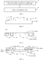
- FIG. 1 is a schematic block diagram of a method for assembling a camera assembly according to an embodiment of this application.
- the assembly method shown in FIG. 1 may include steps 110-120. Steps 110-120 are described in detail below.
- Step 110 Encapsulate a surface mount electronic component and an image sensor to form a target encapsulated module.
- the surface mount electronic component is not specifically limited in this embodiment of this application.
- the surface mount electronic component may be a surface mount device (surface mount device, SMD).
- the SMD may be a surface mount resistive component, a surface mount capacitive device, a small-outline transistor (small-outline transistor, SOT), a small outline integrated circuit (small outline integrated circuit, SOIC) component, or an array chip (for example, a ball grid array (ball grid array, BGA) component, or a micro lead frame (micro lead frame, MLF) component).
- the surface mount device SMD may include, but is not limited to, at least one of the following models: 0201, 0402, 0603, 0805, 1206, 1210, or 2010.
- the SOT transistor may include, but is not limited to, at least one of the following models: SOT23, SOT143, or SOT89.
- the SOIC component may include, but is not limited to, at least one of the following models: SOIC08, SOIC14, SOIC16, SOIC18, SOIC20, SOIC24, SOIC28, or SOIC32.
- the BGA component may be a plastic ball grid array (plastic ball grid array, PBGA) component, an erasable programmable read only memory (erasable programmable read only memory, EPROM) component, or a ceramic plastic ball grid array (ceramic plastic ball grid array, CBGA) component.
- PBGA plastic ball grid array
- EPROM erasable programmable read only memory
- CBGA ceramic plastic ball grid array
- an encapsulating process may be performed to position the surface mount electronic component and the image sensor.
- the molten epoxy resin can be injected into a mold using a high temperature injection molding technology, to wrap various components (for example, the image sensor and at least one surface mount electronic component) in the mold, so that an encapsulated module is formed and each component in the mold is positioned. A solder end of the surface mount electronic component and the solder end of the image sensor in the encapsulated module are exposed on the active surface of the encapsulated module.
- Step 120 Prepare an RDL.
- the RDL may be prepared on a target encapsulated module formed through encapsulating in step 110.
- the RDL may include a dielectric layer and a plurality of metal wirings disposed at the dielectric layer, and at least a part of each metal wiring is disposed on a first surface of the dielectric layer or a second surface opposite the first surface. It should be understood that, for each metal wiring, the remaining part is located at the dielectric layer, except for the part that is located on the first surface or the second surface of the dielectric layer.
- the dielectric layer (which may also be referred to as a substrate) may be used to maintain insulation between portions of each metal wiring located at the dielectric layer and other electronic components located outside the dielectric layer.
- the plurality of metal wirings include two or more metal wirings. It should be noted that the first surface of the dielectric layer is opposite the active surface of the target encapsulated module, or the first surface of the dielectric layer faces the active surface of the target encapsulated module. Accordingly, the second surface of the dielectric layer faces away from the first surface of the dielectric layer.
- the metal wiring exposed on the first surface of the dielectric layer is connected to the solder ends that are of at least one surface mount electronic component and the image sensor and that are exposed on the active surface of the encapsulated module.
- first surface of the dielectric layer is also the first surface of the RDL
- second surface of the dielectric layer is also the second surface of the RDL. That is, being exposed on the first surface of the dielectric layer can be understood as being exposed on the first surface of the RDL, and being exposed on the second surface of the dielectric layer can be understood as being exposed on the second surface of the RDL.
- descriptions of the same or similar cases will be omitted below.
- the RDL in this embodiment of this application is provided with a through-hole.
- the through-hole is opposite a photosensitive area of the image sensor in the encapsulated module, so that the photosensitive area of the image sensor is exposed, and a light signal can be transmitted to the photosensitive area of the image sensor through the through-hole on the RDL.
- An embodiment of this application provides a camera assembly, so as to implement electrical connection between electronic components through metal wiring at a redistribution layer RDL. Because the RDL is thinner than the PCB board in a conventional camera module, the electrical connection between the electronic components is implemented by replacing the PCB with the RDL, so that the overall height of the camera module can be reduced.
- the camera module may further include an infrared filter.
- An infrared filter can also be understood as an optical structure with infrared light filtering. The infrared filter can block the passage of filtered visible light while allowing the passage of infrared light, so that the infrared light can be separated in a light environment in which visible light and infrared light are mixed.
- the infrared filter may be fixed to the second surface of the RDL.
- the infrared filter is opposite the through-hole at the RDL, and the infrared filter and the image sensor in encapsulated module are respectively located on both sides of the RDL.
- the infrared filter may also be embedded in the through-hole at the RDL.
- the camera module may also include a holder, where the holder may be configured to support the infrared filter. The holder is fixed to the second surface of the RDL, and the infrared filter is opposite the through-hole at the RDL.
- FIG. 2 and FIG. 3 Specific implementations of forming a target encapsulated module through an injection molding process in this embodiment of this application are described in more detail below with reference to FIG. 2 and FIG. 3 .
- FIG. 2 and FIG. 3 are merely intended to help those skilled in the art understand the embodiments of this application, and are not intended to limit the embodiments of this application to the specific values or specific scenarios illustrated.
- a person skilled in the art can apparently make various equivalent modifications or changes according to the examples shown in FIG. 2 to FIG. 3 , and such modifications or changes also fall within the scope of the embodiments of this application.
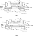
- FIG. 2 is a schematic structural diagram of an assembled electronic component according to an embodiment of this application.
- FIG. 2 may include a tray fixture 210, an image sensor 220, and an SMD device 230.
- This embodiment of this application does not specifically limit the type of the image sensor 220.
- a charge-coupled device (charge-coupled device, CCD) image sensor may be used
- a complementary metal oxide semiconductor (complementary metal oxide semiconductor, CMOS) image sensor may be used
- a photoelectric image sensor may be used.
- the tray fixture 210 may be a load-bearing fixture that covers the adhesive material (for example, glue) on one side.
- the SMD device 230 and the image sensor 220 may be attached to the tray tool 210 (by using glue) based on the design. After the SMD device 230 and the image sensor 220 are attached to the tray fixture 210, the SMD device 230 and the image sensor 220 may be encapsulated through an encapsulating process.
- the encapsulating technology can be injecting molten epoxy into the surroundings of the SMD device 230 and the image sensor 220 using a high temperature injection molding technology, so as to wrap the SMD device 230 and the image sensor 220. Then the encapsulated module may be removed from the tray fixture 210.
- the encapsulating time may be 20 to 40 seconds
- the curing time may be 2 to 3 minutes
- the curing temperature may be 180°C.
- FIG. 3 is a schematic structural diagram of a target encapsulated module 300 according to an embodiment of this application.
- target encapsulated module 300 may correspond to the encapsulated module described in FIG. 2 .
- the target encapsulated module 300 may include an active surface and a passive surface (where the active surface of the target encapsulated module 300 is opposite the passive surface). Soldering pads (also referred to as pins) of the SMD device 230 and the image sensor 220 are exposed on the active surface. An RDL may be fabricated on the soldering pads to implement electrical connection between the SMD device 230 and the image sensor 220.
- the soldering pads of the SMD device 230 and the image sensor 220 may be exposed on the surface of the active surface of the target encapsulated module 300.
- the soldering pads that are of the SMD device 230 and the image sensor 220 and that are exposed on the surface of the active surface of the target encapsulated module 300 may be connected to metal wiring in the prepared RDL, so as to implement electrical connection between the SMD device 230 and the image sensor 220.
- FIG. 4 is a schematic structural diagram of an RDL and the target encapsulated module 300 according to an embodiment of this application.
- the RDL 410 shown in FIG. 4 may be located on one side of the target encapsulated module 300 (for example, the active surface of the target encapsulated module 300).
- the procedure of preparing the RDL 410 on the active surface of the target encapsulated module 300 is described in detail below.
- the dielectric layer 420 is located on the active surface of the target encapsulated module 300, or the dielectric layer 420 is located on the active surface side of the target encapsulated module 300.
- a metal wiring 430 is provided at the dielectric layer 420.
- An exposed part of the metal wiring 430 on the first surface of the dielectric layer 420 may be interconnected with the soldering pads that are of the SMD device 230 and the image sensor 220 and that are exposed on the active surface of the target encapsulated module 300, so as to implement electrical connection between the SMD device 230 and the image sensor 220.
- the exposed part of the metal wiring 430 on the first surface of the dielectric layer 420 may be understood as that the metal wiring 430 is partially exposed on the first surface of the dielectric layer 420.
- the exposed part of the dielectric layer 420 on the first surface of the dielectric layer 420 may be connected to the soldering pads that are of the SMD device 230 and the image sensor 220 and that are exposed on the surface of the active surface of the target encapsulated module 300, so as to implement electrical connection between electronic components (for example, the image sensor 220 and the plurality of SMD devices 230 in FIG. 4 ).
- the RDL 410 is provided with a through-hole 440.
- the through-hole 440 is opposite the photosensitive area of the image sensor 220, so that the photosensitive area of the image sensor 220 is exposed, and a light signal can be incident on the photosensitive area of the image sensor 220 through the through-hole 440 at the RDL 410.
- the metal wiring 430 may be a metal material, for example, copper or aluminum.
- the dielectric layer 420 may be an insulating material, for example, polyimide (polyimide, PI), solder resist film (solder resist film, SRF), or benzocyclobutene (benzocyclobutene, BCB).
- each dielectric layer 420 may be designed to be 20 um; the line width of the metal wiring 430 may be designed to be 5 um; and the spacing between the at least one metal wiring 430 may be designed to be 5 um.
- the RDL 410 may be prepared through processes such as sputtering deposition to a surface, anticorrosion coating, exposure molding with a line lithography system, development, and electrochemical deposition for implementing a copper line layer.
- the camera module may further include an infrared filter and a motor.
- the infrared filter may be fixed to the second surface of the RDL.
- the infrared filter is opposite the through-hole at the RDL, and the infrared filter and the image sensor in encapsulated module are respectively located on both sides of the RDL.
- the motor may be fixed to the second surface of the RDL.
- FIG. 5 A possible camera assembly in an embodiment of this application is described in more detail below with reference to FIG. 5 .
- FIG. 5 is merely intended to help those skilled in the art understand this embodiment of this application, and is not intended to limit this embodiment of this application to the specific value or specific scenario illustrated.
- a person skilled in the art can apparently make various equivalent modifications or changes according to the examples shown in FIG. 5 , and such modifications or changes also fall within the scope of the embodiments of this application.
- FIG. 5 is a schematic structural diagram of a camera assembly 500 according to an embodiment of this application.
- the camera assembly 500 may include a target encapsulated module 300, an RDL 410, an infrared filter 510, a motor 520, and a lens 530.
- the target encapsulated module 300 is an image sensor 220 and a plurality of SMD devices 230.
- the type of the motor 520 is not specifically limited in this embodiment of this application.
- the motor 520 may be, for example, a voice coil motor (voice coil motor, VCM) or an optical zoom motor.
- the infrared filter 510 is located on the second surface of the RDL 410.
- the motor 520 is also located on the second surface of the RDL 410, and the infrared filter 510 is isolated from the motor 520.
- the infrared filter 510 is opposite the through-hole 440 at the RDL 410, and the infrared filter 510 and the image sensor 220 are respectively located on both sides of the RDL 410.
- the infrared filter 510 may be fixed to the second surface of the RDL 410. Further, the motor 520 may be fixed to the second surface of the RDL 410. Still further, the lens 530 may be fixed to the side of the infrared filter 510 facing away from the RDL410 by the motor 520, so that light passing through the infrared filter 510 is incident on the photosensitive area of the image sensor 220 through the through-hole 440, and the assembly of the camera module 500 is completed.
- the fixing may be implemented using an adhesive material, and the adhesive material may be, for example, glue.
- the infrared filter can be fixed to the second surface of the RDL, so that the overall height of the camera module can be reduced.
- the camera module further includes an infrared filter and a motor.
- the infrared filter is fixed in the through-hole. It should be understood that the infrared filter 510 in the camera assembly 500 shown in FIG. 5 may be embedded in the through-hole 440 at the RDL 410.
- the motor is fixed to the second surface of the RDL.
- the outer side wall of the infrared filter 510 is in contact with the inner side wall of the through-hole 440.
- the infrared filter 510 is specifically clamped in the through-hole 440, so that the infrared filter 510 is fixed in the through-hole 440.
- the clamping of the infrared filter 510 in the through-hole 440 means that the outer side wall of the infrared filter 510 and the inner side wall of the through-hole 440 are pressed against each other, so that the frictional force between them can carry the infrared filter 510, thereby fixing the infrared filter 510 in the through-hole 440.
- FIG. 6 A possible camera assembly in an embodiment of this application is described in more detail below with reference to FIG. 6 . It should be noted that the example in FIG. 6 is merely intended to help those skilled in the art understand this embodiment of this application, and is not intended to limit this embodiment of this application to the specific value or specific scenario illustrated. A person skilled in the art can apparently make various equivalent modifications or changes according to the examples shown in FIG. 6 , and such modifications or changes also fall within the scope of the embodiments of this application.
- FIG. 6 is a schematic structural diagram of a possible camera assembly 600 according to an embodiment of this application.
- the camera assembly 600 may include a target encapsulated module 300, an RDL 410, an infrared filter 510, a motor 520, and a lens 530.
- the target encapsulated module 300 is an image sensor 220 and a plurality of SMD devices 230.
- the infrared filter 510 is located in the through-hole 440 of the RDL 410.
- One side of the infrared filter 510 is opposite the image sensor 220.
- the motor 520 is located on the second surface of the RDL 410.
- the infrared filter 510 may be fixed in the through-hole 440 at the RDL 410. Further, the motor 520 may be fixed to the second surface of the RDL 410. Still further, the lens 530 is fixed to the side of the infrared filter 510 facing away from the image sensor 220 by the motor 520, so that light passing through the infrared filter 510 is incident on the photosensitive area of the image sensor 220, and the assembly of the camera module 600 is completed.
- the fixing may be implemented using an adhesive material, and the adhesive material may be, for example, glue.
- the infrared filter can be embedded (or clamped) in the through-hole at the RDL, thereby reducing the height of the camera module in the infrared filter.
- the camera assembly further includes a holder, an infrared filter, and a motor.
- the holder may be configured to support the infrared filter 510 in the camera assembly 500 shown in FIG. 5 .
- the holder is fixed to the second surface of the RDL.
- the infrared filter 510 is opposite the through-hole 440 at the RDL 410, and light passing through the infrared filter 510 is incident on the image sensor 220 through the through-hole 440.
- the motor is fixed to the holder, and the motor and the RDL are respectively located on both sides of the holder.
- FIG. 7 A possible camera assembly in an embodiment of this application is described in more detail below with reference to FIG. 7 . It should be noted that the example in FIG. 7 is merely intended to help those skilled in the art understand this embodiment of this application, and is not intended to limit this embodiment of this application to the specific value or specific scenario illustrated. A person skilled in the art can apparently make various equivalent modifications or changes according to the examples shown in FIG. 7 , and such modifications or changes also fall within the scope of the embodiments of this application.
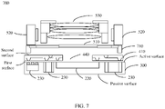
- FIG. 7 is a schematic structural diagram of a possible camera assembly 700 according to an embodiment of this application.
- the camera assembly 700 may include a target encapsulated module 300, an RDL 410, an infrared filter 510, a motor 520, a lens 530, and a holder 710.
- the target encapsulated module 300 is an image sensor 220 and a plurality of SMD devices 230.
- the holder 710 is located on the second surface of the RDL 410.
- the holder 710 may be configured to support the infrared filter 510.
- the infrared filter 510 is opposite the through-hole 440 at the RDL 410, and the infrared filter 510 and the image sensor 220 are respectively located on both sides of the RDL410.
- the motor 520 is located on the holder 710, and the motor 520 and the RDL 410 are respectively located on both sides of the holder 710.
- the holder 710 may be fixed to the second surface of the RDL 410.
- the infrared filter 510 may be fixed to the holder 710.
- the motor 520 may be fixed to the holder 710, and the motor 520 and the RDL 410 are respectively located on both sides of the holder 710.
- the lens 530 may be fixed to the side of the infrared filter 510 facing away from the RDL410 by the motor 520, so that light passing through the infrared filter 510 is incident on the photosensitive area of the image sensor 220 through the through-hole 440, and the assembly of the camera module 700 is completed.
- the fixing may be implemented using an adhesive material, and the adhesive material may be, for example, glue.
- the infrared filter can be fixed to the second surface of the RDL using the holder, so that the infrared filter can be closer to the lens, and the infrared light can be better blocked from entering the image sensor.
Landscapes
- Engineering & Computer Science (AREA)
- Multimedia (AREA)
- Signal Processing (AREA)
- Physics & Mathematics (AREA)
- General Physics & Mathematics (AREA)
- Optics & Photonics (AREA)
- Health & Medical Sciences (AREA)
- Toxicology (AREA)
- Studio Devices (AREA)
Description
- This application relates to the field of semiconductor technologies, and more specifically, to a camera assembly, an assembly method, and a terminal.
- As the design of current mobile phones tends to be miniaturized and ultra-thin, the camera module, as an important module component of the mobile phone, also faces the challenges of miniaturization and ultra-thinness. In particular, the current high screen-to-body ratio and the full screen design have increased the need for a reduction in the outer dimensions of the camera module.The document
US 2008/083980 A1 is a relevant prior art. - An architecture of a conventional camera module includes a printed circuit board (printed circuit board, PCB), a soldering process, a gold wire bonding process, and the like. Conventional PCBs are bulky, and the size of the PCB will direct affect the size of the camera module.
- Therefore, how to reduce the height of the camera module becomes a problem that needs to be urgently resolved.
- This application provides a camera assembly, an assembly method, and a terminal, so as to implement an electrical connection between electronic components through metal wiring at a redistribution layer (redistribution layer, RDL). Because the RDL is thinner than the PCB board in a conventional camera module, the electrical connection between electronic components is implemented by replacing the PCB with the RDL, so that the overall height of the camera module can be reduced.
- According to a first aspect, a method for assembling a camera assembly is provided, including the following steps:
- encapsulating a surface mount electronic component and an image sensor to form a target encapsulated module, where the target encapsulated module includes an active surface, and a solder end of the surface mount electronic component and the solder end of the image sensor are exposed on the active surface;
- preparing a redistribution layer RDL, and drilling the RDL to form a through-hole, where the through-hole is opposite to a photosensitive area of the image sensor, the RDL includes a dielectric layer and metal wiring disposed at the dielectric layer, and the metal wiring is at least partially exposed on a first surface of the RDL; and connecting the metal wiring exposed on the first surface of the RDL to a solder end on the active surface of the target encapsulated module.
- In this embodiment of this application, the electrical connection between the electronic components can be implemented through the metal wiring at the RDL. Because the RDL is thinner than the PCB board in a conventional camera module, when the electrical connection between the electronic components is implemented by replacing the PCB with the RDL, the overall height of the camera module can be reduced.
- With reference to the first aspect, in any possible implementation of the first aspect, the method further includes: fixing an infrared filter to a second surface of the RDL. The second surface of the RDL faces away from the first surface of the RDL. The infrared filter is opposite the through-hole, and light passing through the infrared filter is incident on the image sensor through the through-hole.
- In this embodiment of this application, the infrared filter can be fixed to the second surface of the RDL, so that the overall height of the camera module can be reduced.
- With reference to the first aspect, in any possible implementation of the first aspect, the infrared filter is fixed in the through-hole.
- In this embodiment of this application, the infrared filter can be fixed in the through-hole at the RDL, so that the impact of the infrared filter on the height of the camera module can be further reduced, and the overall height of the camera module can be reduced.
- With reference to the first aspect, in any possible implementation of the second aspect, a motor is fixed to the second surface of the RDL.
- With reference to the first aspect, in any possible implementation of the first aspect, further including: fixing a holder to the second surface of the RDL. The holder is configured to support the infrared filter. The infrared filter is opposite the through-hole, and light passing through the infrared filter is incident on the image sensor through the through-hole.
- In this embodiment of this application, the infrared filter can be fixed to the second surface of the RDL using the holder, so that the infrared filter can be closer to the lens, and the infrared light can be better blocked from entering the image sensor.
- With reference to the first aspect, in any possible implementation of the second aspect, a motor is fixed to the holder, and the motor and the RDL are respectively located on both sides of the holder.
- With reference to the first aspect, in any possible implementation of the first aspect, the surface mount electronic component and the image sensor are placed on a tray fixture. The surface mount electronic component and the image sensor are wrapped by an encapsulating material.
- In this embodiment of this application, the surface mount electronic component and the image sensor in the target encapsulated module can be positioned using the encapsulating material, so that the electrical connection between the electronic components can be better implemented.
- Optionally, the encapsulating material is an epoxy resin material.
- According to a second aspect, a camera assembly is provided, including a target encapsulated module and a redistribution layer RDL. The connection relationships between the foregoing modules are described in detail below.
- A surface mount electronic component and an image sensor are encapsulated on the target encapsulated module. The target encapsulated module includes an active surface, and a solder end of the surface mount electronic component and the solder end of the image sensor are exposed on the active surface.
- The redistribution layer RDL is provided with a through-hole. The through-hole is opposite a photosensitive area of the image sensor. The RDL includes a dielectric layer and metal wiring disposed at the dielectric layer. The metal wiring is at least partially exposed on a first surface of the RDL.
- The metal wiring exposed on the first surface of the RDL is connected to a solder end on the active surface of the target encapsulated module.
- In this embodiment of this application, the electrical connection between the electronic components can be implemented through the metal wiring at the RDL. Because the RDL is thinner than the PCB board in a conventional camera module, when the electrical connection between the electronic components is implemented by replacing the PCB with the RDL, the overall height of the camera module can be reduced.
- With reference to the second aspect, in any possible implementation of the second aspect, the camera assembly further includes an infrared filter, where the infrared filter is fixed to a second surface of the RDL. The second surface of the RDL faces away from the first surface of the RDL. The infrared filter is opposite the through-hole, and light passing through the infrared filter is incident on the image sensor through the through-hole.
- In this embodiment of this application, the infrared filter can be fixed to the second surface of the RDL, so that the overall height of the camera module can be reduced.
- With reference to the second aspect, in any possible implementation of the second aspect, the camera assembly further includes an infrared filter, where the infrared filter is fixed in the through-hole.
- In this embodiment of this application, the infrared filter can be fixed in the through-hole at the RDL, so that the impact of the infrared filter on the height of the camera module can be further reduced, and the overall height of the camera module can be reduced.
- With reference to the second aspect, in any possible implementation of the second aspect, the camera assembly further includes a motor, where the motor is fixed to the second surface of the RDL.
- With reference to the second aspect, in any possible implementation of the second aspect, the camera assembly further includes a holder and an infrared filter. The holder is configured to support the infrared filter. The holder is fixed to the second surface of the RDL. The infrared filter is opposite the through-hole, and light passing through the infrared filter is incident on the image sensor through the through-hole.
- In this embodiment of this application, the infrared filter can be fixed to the second surface of the RDL using the holder, so that the infrared filter can be closer to the lens, and the infrared light can be better blocked from entering the image sensor.
- With reference to the second aspect, in any possible implementation of the second aspect, the camera assembly further includes a motor, where the motor is fixed to the holder, and the motor and the RDL are respectively located on both sides of the holder.
- With reference to the second aspect, in any possible implementation of the second aspect, the target encapsulated module further includes an encapsulating material. The encapsulating material surrounds a surface mount electronic component in the target encapsulated module and an image sensor.
- In this embodiment of this application, the surface mount electronic component and the image sensor in the target encapsulated module can be positioned using the encapsulating material, so that the electrical connection between the electronic components can be better implemented.
- Optionally, the encapsulating material is an epoxy resin material.
- According to a third aspect, a terminal is provided, including a camera assembly according to the second aspect or any possible implementation of the second aspect and a processor configured to control the camera assembly.
-
-
FIG. 1 is a schematic block diagram of a method for assembling a camera assembly according to an embodiment of this application; -
FIG. 2 is a schematic structural diagram of an assembled electronic component according to an embodiment of this application; -
FIG. 3 is a schematic structural diagram of a target encapsulatedmodule 300 according to an embodiment of this application; -
FIG. 4 is a schematic structural diagram of an RDL and the target encapsulatedmodule 300 according to an embodiment of this application; -
FIG. 5 is a schematic structural diagram of a possible camera assembly 500 according to an embodiment of this application; -
FIG. 6 is a schematic structural diagram of apossible camera assembly 600 according to an embodiment of this application; and -
FIG. 7 is a schematic structural diagram of apossible camera assembly 700 according to an embodiment of this application. - The following describes technical solutions of this application with reference to accompanying drawings.
- It should be understood that the type of a terminal device mentioned in the embodiments of this application is not specifically limited, and the terminal device may include, but is not limited to, a mobile station (mobile station, MS), a mobile telephone (mobile telephone), user equipment (UE), a handset (handset), portable equipment (portable equipment), a cellular telephone, a cordless telephone, a session initiation protocol (session initiation protocol, SIP) telephone, a wireless local loop (wireless local loop, WLL) station, a personal digital assistant (personal digital assistant, PDA), a radio frequency identification (radio frequency identification, RFID) terminal device for logistics, a handheld device having a wireless communication function, a computing device, another device connected to a wireless modem, an in-vehicle device, a wearable device, or a terminal device in an Internet of Things or an Internet of vehicles.
- By way of example but not limitation, in an embodiment of this application, the terminal device may alternatively be a wearable device. A wearable device may also be referred to as a wearable smart device, and is a general term for daily wearable devices that are smartly designed and developed by using wearable technologies, such as glasses, gloves, watches, apparels, and shoes. A wearable device is a portable device that can be worn directly on the body or integrated into the clothing or accessories of a user. The wearable device is not merely a hardware device, it can implement a powerful function based on software support, and data interaction, and cloud interaction. Generalized wearable smart devices include large-sized smart devices that can implement some functions without relying on a smartphone, such as smartwatches or smart glasses, and also include smart devices that focus on a particular application function and need to work with another device such as a smartphone, such as smart bands and smart jewelry that are used for sign monitoring.
- An embodiment of this application provides a camera assembly, so as to implement electrical connection between electronic components through metal wiring at a redistribution layer (redistribution layer, RDL). Because the RDL is thinner than the PCB board in a conventional camera module, the electrical connection between the electronic components is implemented by replacing the PCB with the RDL, so that the overall height of the camera module can be reduced.
- A method for assembling a camera assembly according to an embodiment of this application is described in detail below with reference to
FIG. 1 . -
FIG. 1 is a schematic block diagram of a method for assembling a camera assembly according to an embodiment of this application. The assembly method shown inFIG. 1 may include steps 110-120. Steps 110-120 are described in detail below. - Step 110: Encapsulate a surface mount electronic component and an image sensor to form a target encapsulated module.
- The surface mount electronic component is not specifically limited in this embodiment of this application. Optionally, by way of example, the surface mount electronic component may be a surface mount device (surface mount device, SMD). For example, the SMD may be a surface mount resistive component, a surface mount capacitive device, a small-outline transistor (small-outline transistor, SOT), a small outline integrated circuit (small outline integrated circuit, SOIC) component, or an array chip (for example, a ball grid array (ball grid array, BGA) component, or a micro lead frame (micro lead frame, MLF) component).
- The surface mount device SMD may include, but is not limited to, at least one of the following models: 0201, 0402, 0603, 0805, 1206, 1210, or 2010. The SOT transistor may include, but is not limited to, at least one of the following models: SOT23, SOT143, or SOT89. The SOIC component may include, but is not limited to, at least one of the following models: SOIC08, SOIC14, SOIC16, SOIC18, SOIC20, SOIC24, SOIC28, or SOIC32. The BGA component may be a plastic ball grid array (plastic ball grid array, PBGA) component, an erasable programmable read only memory (erasable programmable read only memory, EPROM) component, or a ceramic plastic ball grid array (ceramic plastic ball grid array, CBGA) component.
- In this embodiment of this application, an encapsulating process may be performed to position the surface mount electronic component and the image sensor.
- Specifically, the molten epoxy resin can be injected into a mold using a high temperature injection molding technology, to wrap various components (for example, the image sensor and at least one surface mount electronic component) in the mold, so that an encapsulated module is formed and each component in the mold is positioned. A solder end of the surface mount electronic component and the solder end of the image sensor in the encapsulated module are exposed on the active surface of the encapsulated module. A specific implementation of forming the target encapsulated module will be described below with reference to
FIG. 2 , and therefore is not first described in detail herein. - In this embodiment of this application, the RDL may be prepared on a target encapsulated module formed through encapsulating in
step 110. The RDL may include a dielectric layer and a plurality of metal wirings disposed at the dielectric layer, and at least a part of each metal wiring is disposed on a first surface of the dielectric layer or a second surface opposite the first surface. It should be understood that, for each metal wiring, the remaining part is located at the dielectric layer, except for the part that is located on the first surface or the second surface of the dielectric layer. The dielectric layer (which may also be referred to as a substrate) may be used to maintain insulation between portions of each metal wiring located at the dielectric layer and other electronic components located outside the dielectric layer. It should also be noted that the plurality of metal wirings include two or more metal wirings. It should be noted that the first surface of the dielectric layer is opposite the active surface of the target encapsulated module, or the first surface of the dielectric layer faces the active surface of the target encapsulated module. Accordingly, the second surface of the dielectric layer faces away from the first surface of the dielectric layer. - In this embodiment of this application, the metal wiring exposed on the first surface of the dielectric layer is connected to the solder ends that are of at least one surface mount electronic component and the image sensor and that are exposed on the active surface of the encapsulated module.
- It should be noted that the first surface of the dielectric layer is also the first surface of the RDL, and the second surface of the dielectric layer is also the second surface of the RDL. That is, being exposed on the first surface of the dielectric layer can be understood as being exposed on the first surface of the RDL, and being exposed on the second surface of the dielectric layer can be understood as being exposed on the second surface of the RDL. For brevity, descriptions of the same or similar cases will be omitted below.
- The RDL in this embodiment of this application is provided with a through-hole. The through-hole is opposite a photosensitive area of the image sensor in the encapsulated module, so that the photosensitive area of the image sensor is exposed, and a light signal can be transmitted to the photosensitive area of the image sensor through the through-hole on the RDL.
- It should be understood that a specific implementation of preparing the RDL will be described below with reference to
FIG. 4 , and therefore is not first described in detail herein. - An embodiment of this application provides a camera assembly, so as to implement electrical connection between electronic components through metal wiring at a redistribution layer RDL. Because the RDL is thinner than the PCB board in a conventional camera module, the electrical connection between the electronic components is implemented by replacing the PCB with the RDL, so that the overall height of the camera module can be reduced.
- Optionally, in some embodiments, the camera module may further include an infrared filter. An infrared filter can also be understood as an optical structure with infrared light filtering. The infrared filter can block the passage of filtered visible light while allowing the passage of infrared light, so that the infrared light can be separated in a light environment in which visible light and infrared light are mixed.
- The position of the infrared filter is not specifically limited in this embodiment of this application. By way of example, the infrared filter may be fixed to the second surface of the RDL. In addition, the infrared filter is opposite the through-hole at the RDL, and the infrared filter and the image sensor in encapsulated module are respectively located on both sides of the RDL. As another example, the infrared filter may also be embedded in the through-hole at the RDL. As another example, the camera module may also include a holder, where the holder may be configured to support the infrared filter. The holder is fixed to the second surface of the RDL, and the infrared filter is opposite the through-hole at the RDL. The camera assemblies with the foregoing connection relationships will be described in detail below with reference to
FIG. 4 to FIG. 6 , and therefore are not first described in detail herein. - Specific implementations of forming a target encapsulated module through an injection molding process in this embodiment of this application are described in more detail below with reference to
FIG. 2 and FIG. 3 . It should be noted that the examples inFIG. 2 and FIG. 3 are merely intended to help those skilled in the art understand the embodiments of this application, and are not intended to limit the embodiments of this application to the specific values or specific scenarios illustrated. A person skilled in the art can apparently make various equivalent modifications or changes according to the examples shown inFIG. 2 to FIG. 3 , and such modifications or changes also fall within the scope of the embodiments of this application. -
FIG. 2 is a schematic structural diagram of an assembled electronic component according to an embodiment of this application.FIG. 2 may include atray fixture 210, animage sensor 220, and anSMD device 230. - This embodiment of this application does not specifically limit the type of the
image sensor 220. For example, a charge-coupled device (charge-coupled device, CCD) image sensor may be used, a complementary metal oxide semiconductor (complementary metal oxide semiconductor, CMOS) image sensor may be used, or a photoelectric image sensor may be used. - The
tray fixture 210 may be a load-bearing fixture that covers the adhesive material (for example, glue) on one side. TheSMD device 230 and theimage sensor 220 may be attached to the tray tool 210 (by using glue) based on the design. After theSMD device 230 and theimage sensor 220 are attached to thetray fixture 210, theSMD device 230 and theimage sensor 220 may be encapsulated through an encapsulating process. - The encapsulating technology can be injecting molten epoxy into the surroundings of the
SMD device 230 and theimage sensor 220 using a high temperature injection molding technology, so as to wrap theSMD device 230 and theimage sensor 220. Then the encapsulated module may be removed from thetray fixture 210. - Specifically, in the foregoing encapsulating procedure, the encapsulating time may be 20 to 40 seconds, the curing time may be 2 to 3 minutes, and the curing temperature may be 180°C.
- For the encapsulated body removed from the
tray fixture 210, reference may be made toFIG. 3 . -
FIG. 3 is a schematic structural diagram of a target encapsulatedmodule 300 according to an embodiment of this application. - It should be understood that the target encapsulated
module 300 may correspond to the encapsulated module described inFIG. 2 . - Referring to
FIG. 3 , the target encapsulatedmodule 300 may include an active surface and a passive surface (where the active surface of the target encapsulatedmodule 300 is opposite the passive surface). Soldering pads (also referred to as pins) of theSMD device 230 and theimage sensor 220 are exposed on the active surface. An RDL may be fabricated on the soldering pads to implement electrical connection between theSMD device 230 and theimage sensor 220. - It should be noted that the side of the
SMD device 230 and the side of theimage sensor 220 that are in contact with thetray fixture 210 are not encapsulated because of the protection of thetray fixture 210. Therefore, the soldering pads of theSMD device 230 and theimage sensor 220 may be exposed on the surface of the active surface of the target encapsulatedmodule 300. The soldering pads that are of theSMD device 230 and theimage sensor 220 and that are exposed on the surface of the active surface of the target encapsulatedmodule 300 may be connected to metal wiring in the prepared RDL, so as to implement electrical connection between theSMD device 230 and theimage sensor 220. A description will be provided below with reference toFIG. 4 , so no detailed description is first provided herein.FIG. 4 is a schematic structural diagram of an RDL and the target encapsulatedmodule 300 according to an embodiment of this application. TheRDL 410 shown inFIG. 4 may be located on one side of the target encapsulated module 300 (for example, the active surface of the target encapsulated module 300). The procedure of preparing theRDL 410 on the active surface of the target encapsulatedmodule 300 is described in detail below. - The
dielectric layer 420 is located on the active surface of the target encapsulatedmodule 300, or thedielectric layer 420 is located on the active surface side of the target encapsulatedmodule 300. Ametal wiring 430 is provided at thedielectric layer 420. An exposed part of themetal wiring 430 on the first surface of thedielectric layer 420 may be interconnected with the soldering pads that are of theSMD device 230 and theimage sensor 220 and that are exposed on the active surface of the target encapsulatedmodule 300, so as to implement electrical connection between theSMD device 230 and theimage sensor 220. - It should be noted that the exposed part of the
metal wiring 430 on the first surface of thedielectric layer 420 may be understood as that themetal wiring 430 is partially exposed on the first surface of thedielectric layer 420. In addition, the exposed part of thedielectric layer 420 on the first surface of thedielectric layer 420 may be connected to the soldering pads that are of theSMD device 230 and theimage sensor 220 and that are exposed on the surface of the active surface of the target encapsulatedmodule 300, so as to implement electrical connection between electronic components (for example, theimage sensor 220 and the plurality ofSMD devices 230 inFIG. 4 ). - The
RDL 410 is provided with a through-hole 440. The through-hole 440 is opposite the photosensitive area of theimage sensor 220, so that the photosensitive area of theimage sensor 220 is exposed, and a light signal can be incident on the photosensitive area of theimage sensor 220 through the through-hole 440 at theRDL 410. - In this embodiment of this application, the
metal wiring 430 may be a metal material, for example, copper or aluminum. Thedielectric layer 420 may be an insulating material, for example, polyimide (polyimide, PI), solder resist film (solder resist film, SRF), or benzocyclobutene (benzocyclobutene, BCB). - In this embodiment of this application, the thickness of each
dielectric layer 420 may be designed to be 20 um; the line width of themetal wiring 430 may be designed to be 5 um; and the spacing between the at least onemetal wiring 430 may be designed to be 5 um. - The
RDL 410 may be prepared through processes such as sputtering deposition to a surface, anticorrosion coating, exposure molding with a line lithography system, development, and electrochemical deposition for implementing a copper line layer. - Optionally, in some embodiments, the camera module may further include an infrared filter and a motor. The infrared filter may be fixed to the second surface of the RDL. In addition, the infrared filter is opposite the through-hole at the RDL, and the infrared filter and the image sensor in encapsulated module are respectively located on both sides of the RDL. The motor may be fixed to the second surface of the RDL.
- A possible camera assembly in an embodiment of this application is described in more detail below with reference to
FIG. 5 . It should be noted that the example inFIG. 5 is merely intended to help those skilled in the art understand this embodiment of this application, and is not intended to limit this embodiment of this application to the specific value or specific scenario illustrated. A person skilled in the art can apparently make various equivalent modifications or changes according to the examples shown inFIG. 5 , and such modifications or changes also fall within the scope of the embodiments of this application. -
FIG. 5 is a schematic structural diagram of a camera assembly 500 according to an embodiment of this application. The camera assembly 500 may include a target encapsulatedmodule 300, anRDL 410, aninfrared filter 510, amotor 520, and alens 530. The target encapsulatedmodule 300 is animage sensor 220 and a plurality ofSMD devices 230. - The type of the
motor 520 is not specifically limited in this embodiment of this application. Themotor 520 may be, for example, a voice coil motor (voice coil motor, VCM) or an optical zoom motor. - Referring to
FIG. 5 , theinfrared filter 510 is located on the second surface of theRDL 410. Themotor 520 is also located on the second surface of theRDL 410, and theinfrared filter 510 is isolated from themotor 520. Theinfrared filter 510 is opposite the through-hole 440 at theRDL 410, and theinfrared filter 510 and theimage sensor 220 are respectively located on both sides of theRDL 410. - Specifically, the
infrared filter 510 may be fixed to the second surface of theRDL 410. Further, themotor 520 may be fixed to the second surface of theRDL 410. Still further, thelens 530 may be fixed to the side of theinfrared filter 510 facing away from the RDL410 by themotor 520, so that light passing through theinfrared filter 510 is incident on the photosensitive area of theimage sensor 220 through the through-hole 440, and the assembly of the camera module 500 is completed. - It should be understood that this embodiment of this application does not limit the specific implementation of the fixing. By way of example, the fixing may be implemented using an adhesive material, and the adhesive material may be, for example, glue.
- In this embodiment of this application, the infrared filter can be fixed to the second surface of the RDL, so that the overall height of the camera module can be reduced.
- Optionally, in some embodiments, the camera module further includes an infrared filter and a motor. The infrared filter is fixed in the through-hole. It should be understood that the
infrared filter 510 in the camera assembly 500 shown inFIG. 5 may be embedded in the through-hole 440 at theRDL 410. The motor is fixed to the second surface of the RDL. - Optionally, the outer side wall of the
infrared filter 510 is in contact with the inner side wall of the through-hole 440. - Optionally, the
infrared filter 510 is specifically clamped in the through-hole 440, so that theinfrared filter 510 is fixed in the through-hole 440. - It should be understood that the clamping of the
infrared filter 510 in the through-hole 440 means that the outer side wall of theinfrared filter 510 and the inner side wall of the through-hole 440 are pressed against each other, so that the frictional force between them can carry theinfrared filter 510, thereby fixing theinfrared filter 510 in the through-hole 440. - A possible camera assembly in an embodiment of this application is described in more detail below with reference to
FIG. 6 . It should be noted that the example inFIG. 6 is merely intended to help those skilled in the art understand this embodiment of this application, and is not intended to limit this embodiment of this application to the specific value or specific scenario illustrated. A person skilled in the art can apparently make various equivalent modifications or changes according to the examples shown inFIG. 6 , and such modifications or changes also fall within the scope of the embodiments of this application. -
FIG. 6 is a schematic structural diagram of apossible camera assembly 600 according to an embodiment of this application. Thecamera assembly 600 may include a target encapsulatedmodule 300, anRDL 410, aninfrared filter 510, amotor 520, and alens 530. The target encapsulatedmodule 300 is animage sensor 220 and a plurality ofSMD devices 230. - Referring to
FIG. 6 , theinfrared filter 510 is located in the through-hole 440 of theRDL 410. One side of theinfrared filter 510 is opposite theimage sensor 220. Themotor 520 is located on the second surface of theRDL 410. - Specifically, the
infrared filter 510 may be fixed in the through-hole 440 at theRDL 410. Further, themotor 520 may be fixed to the second surface of theRDL 410. Still further, thelens 530 is fixed to the side of theinfrared filter 510 facing away from theimage sensor 220 by themotor 520, so that light passing through theinfrared filter 510 is incident on the photosensitive area of theimage sensor 220, and the assembly of thecamera module 600 is completed. - It should be understood that this embodiment of this application does not limit the specific implementation of the fixing. By way of example, the fixing may be implemented using an adhesive material, and the adhesive material may be, for example, glue.
- In this embodiment of this application, the infrared filter can be embedded (or clamped) in the through-hole at the RDL, thereby reducing the height of the camera module in the infrared filter.
- Optionally, in some embodiments, the camera assembly further includes a holder, an infrared filter, and a motor. The holder may be configured to support the
infrared filter 510 in the camera assembly 500 shown inFIG. 5 . The holder is fixed to the second surface of the RDL. Theinfrared filter 510 is opposite the through-hole 440 at theRDL 410, and light passing through theinfrared filter 510 is incident on theimage sensor 220 through the through-hole 440. The motor is fixed to the holder, and the motor and the RDL are respectively located on both sides of the holder. - A possible camera assembly in an embodiment of this application is described in more detail below with reference to
FIG. 7 . It should be noted that the example inFIG. 7 is merely intended to help those skilled in the art understand this embodiment of this application, and is not intended to limit this embodiment of this application to the specific value or specific scenario illustrated. A person skilled in the art can apparently make various equivalent modifications or changes according to the examples shown inFIG. 7 , and such modifications or changes also fall within the scope of the embodiments of this application. -
FIG. 7 is a schematic structural diagram of apossible camera assembly 700 according to an embodiment of this application. Thecamera assembly 700 may include a target encapsulatedmodule 300, anRDL 410, aninfrared filter 510, amotor 520, alens 530, and aholder 710. The target encapsulatedmodule 300 is animage sensor 220 and a plurality ofSMD devices 230. - Referring to
FIG. 7 , theholder 710 is located on the second surface of theRDL 410. Theholder 710 may be configured to support theinfrared filter 510. Theinfrared filter 510 is opposite the through-hole 440 at theRDL 410, and theinfrared filter 510 and theimage sensor 220 are respectively located on both sides of the RDL410. Further, themotor 520 is located on theholder 710, and themotor 520 and theRDL 410 are respectively located on both sides of theholder 710. - Specifically, the
holder 710 may be fixed to the second surface of theRDL 410. Further, theinfrared filter 510 may be fixed to theholder 710. Still further, themotor 520 may be fixed to theholder 710, and themotor 520 and theRDL 410 are respectively located on both sides of theholder 710. Still further, thelens 530 may be fixed to the side of theinfrared filter 510 facing away from the RDL410 by themotor 520, so that light passing through theinfrared filter 510 is incident on the photosensitive area of theimage sensor 220 through the through-hole 440, and the assembly of thecamera module 700 is completed. - It should be understood that this embodiment of this application does not limit the specific implementation of the fixing. By way of example, the fixing may be implemented using an adhesive material, and the adhesive material may be, for example, glue.
- In this embodiment of this application, the infrared filter can be fixed to the second surface of the RDL using the holder, so that the infrared filter can be closer to the lens, and the infrared light can be better blocked from entering the image sensor.
- It should be understood that, the term "and/or" in the embodiments of this application describes only an association relationship for describing associated objects and represents that three relationships may exist. For example, A and/or B may represent the following cases: Only A exists, both A and B exist, and only B exists. In addition, the character "/" in this specification generally indicates an "or" relationship between the associated objects.
- The foregoing descriptions are merely specific implementations of this application, but are not intended to limit the protection scope of this application. Any variation or replacement readily figured out by a person skilled in the art within the technical scope disclosed in this application shall fall within the protection scope of this application. Therefore, the protection scope of this application shall be subject to the protection scope of the claims.
Claims (15)
- A method for assembling a camera assembly (500, 600,700) wherein the method comprises:encapsulating a surface mount electronic component (230) and an image sensor (220) to form a target encapsulated module, where the target encapsulated module includes an active surface, and a solder end of the surface mount electronic component and a solder end of the image sensor are exposed on the active surface;preparing a redistribution layer RDL (410) and drilling the RDL to form a through-hole (440) where the through-hole is opposite to a photosensitive area of the image sensor, the RDL includes a dielectric layer (420) and metal wiring (430)disposed at the dielectric layer, and the metal wiring is at least partially exposed on a first surface of the RDL; and connecting the metal wiring exposed on the first surface of the RDL to the solder end of the surface mount electronic component and the solder end of the image sensor on the active surface of the target encapsulated module.
- The method according to claim 1, wherein the method further comprises:fixing an infrared filter (510)to a second surface of the RDL, wherein the second surface of the RDL faces away from the first surface of the RDL, the infrared filter is opposite to the through-hole, and light passing through the infrared filter is incident on the image sensor through the through-hole.
- The method according to claim 2, , wherein the infrared filter is fixed in the through-hole.
- The method of claim 2 or 3, further comprising: fixing a motor (520) to the second surface of the RDL.
- The method according to claim 1, further comprising:
fixing a holder (710) to the second surface of the RDL, wherein the holder is configured to support the infrared filter, the infrared filter is opposite to the through-hole, and light passing through the infrared filter is incident on the image sensor through the through-hole. - The method according to claim 5, wherein a motor is fixed to the holder, and the motor and the RDL are respectively located on both sides of the holder.
- The method according to any one of claims 1 to 6, wherein the encapsulating a surface mount electronic component and an image sensor to form a target encapsulated module comprises:placing the surface mount electronic component and the image sensor on a tray fixture; andwrapping the surface mount electronic component and the image sensor by an encapsulating material.
- A camera assembly (500,600,700), comprising:a target encapsulated module encapsulated with a surface mount electronic component (230) and an image sensor (220),wherein the target encapsulated module comprises an active surface, and a solder end of the surface mount electronic component and a solder end of the image sensor are exposed on the active surface; anda redistribution layer RDL (410) with a through-hole (440), wherein the through-hole is opposite to a photosensitive area of the image sensor, the RDL comprises a dielectric layer (420) and metal wiring (430) disposed at the dielectric layer, the metal wiring is at least partially exposed on a first surface of the RDL, andcharacterised in that the
metal wiring exposed on the first surface of the RDL is connected to the solder end of the surface mount electronic component and the solder end of the image sensor on the active surface of the target encapsulated module. - The camera assembly according to claim 8, further comprising:
an infrared filter, wherein the infrared filter is fixed to a second surface of the RDL, the second surface of the RDL faces away from the first surface of the RDL, the infrared filter is opposite to the through-hole, and light passing through the infrared filter is incident on the image sensor through the through-hole. - The camera assembly according to claim 8, further comprising an infrared filter, wherein the infrared filter is fixed in the through-hole.
- The camera assembly according to claim 9 or 10, further comprising:
a motor, wherein the motor is fixed to the second surface of the RDL. - The camera assembly according to claim 8, further comprising a holder and an infrared filter, wherein
the holder is configured to support the infrared filter, the holder is fixed to the second surface of the RDL, the infrared filter is opposite to the through-hole, and light passing through the infrared filter is incident on the image sensor through the through-hole. - The camera assembly according to claim 12, further comprising a motor, wherein the motor is fixed to the holder, and the motor and the RDL are respectively located on both sides of the holder.
- The camera assembly according to any one of claims 8 to 13, wherein the target encapsulated module further comprises an encapsulating material, and the encapsulating material surrounds a surface mount electronic component in the target encapsulated module and an image sensor.
- A terminal, comprising a camera assembly according to any one of claims 8 to 14 and a processor configured to control the camera assembly.
Applications Claiming Priority (2)
| Application Number | Priority Date | Filing Date | Title |
|---|---|---|---|
| CN201811155503.0A CN109461746A (en) | 2018-09-30 | 2018-09-30 | A kind of CCD camera assembly, assemble method and terminal |
| PCT/CN2019/090232 WO2020062915A1 (en) | 2018-09-30 | 2019-06-06 | Camera assembly, assembly method therefor, and terminal |
Publications (3)
| Publication Number | Publication Date |
|---|---|
| EP3780104A1 EP3780104A1 (en) | 2021-02-17 |
| EP3780104A4 EP3780104A4 (en) | 2021-06-09 |
| EP3780104B1 true EP3780104B1 (en) | 2022-08-24 |
Family
ID=65607233
Family Applications (1)
| Application Number | Title | Priority Date | Filing Date |
|---|---|---|---|
| EP19864283.7A Active EP3780104B1 (en) | 2018-09-30 | 2019-06-06 | Camera assembly, assembly method therefor, and terminal |
Country Status (4)
| Country | Link |
|---|---|
| US (1) | US20210075940A1 (en) |
| EP (1) | EP3780104B1 (en) |
| CN (1) | CN109461746A (en) |
| WO (1) | WO2020062915A1 (en) |
Families Citing this family (5)
| Publication number | Priority date | Publication date | Assignee | Title |
|---|---|---|---|---|
| CN109461746A (en) * | 2018-09-30 | 2019-03-12 | 华为技术有限公司 | A kind of CCD camera assembly, assemble method and terminal |
| CN110099202A (en) * | 2019-04-24 | 2019-08-06 | 维沃移动通信(杭州)有限公司 | Camera module, terminal equipment and method of making the camera module |
| CN111866323A (en) * | 2019-04-30 | 2020-10-30 | 宁波舜宇光电信息有限公司 | Camera module and its photosensitive assembly, electronic equipment and preparation method |
| CN111866322A (en) * | 2019-04-30 | 2020-10-30 | 宁波舜宇光电信息有限公司 | Camera module and its photosensitive assembly, electronic equipment and preparation method |
| DE102024134469A1 (en) * | 2024-11-22 | 2026-05-28 | Pac Tech - Packaging Technologies Gmbh | Electronic device for a camera module, method for its manufacture and camera module |
Family Cites Families (25)
| Publication number | Priority date | Publication date | Assignee | Title |
|---|---|---|---|---|
| TWI303105B (en) * | 2006-01-11 | 2008-11-11 | Advanced Semiconductor Eng | Wafer level package for image sensor components and its fabricating method |
| US20080083980A1 (en) * | 2006-10-06 | 2008-04-10 | Advanced Chip Engineering Technology Inc. | Cmos image sensor chip scale package with die receiving through-hole and method of the same |
| US20080211075A1 (en) * | 2006-10-06 | 2008-09-04 | Advanced Chip Engineering Technology Inc. | Image sensor chip scale package having inter-adhesion with gap and method of the same |
| US20080173792A1 (en) * | 2007-01-23 | 2008-07-24 | Advanced Chip Engineering Technology Inc. | Image sensor module and the method of the same |
| US20090045476A1 (en) * | 2007-08-16 | 2009-02-19 | Kingpak Technology Inc. | Image sensor package and method for forming the same |
| KR20110001659A (en) * | 2009-06-30 | 2011-01-06 | 삼성테크윈 주식회사 | Camera module |
| US20110221018A1 (en) * | 2010-03-15 | 2011-09-15 | Xunqing Shi | Electronic Device Package and Methods of Manufacturing an Electronic Device Package |
| US8934052B2 (en) * | 2010-11-02 | 2015-01-13 | Stmicroelectronics Pte Ltd | Camera module including an image sensor and a laterally adjacent surface mount device coupled at a lower surface of a dielectric material layer |
| JP5329629B2 (en) * | 2011-09-26 | 2013-10-30 | シャープ株式会社 | The camera module |
| CN105845635B (en) * | 2015-01-16 | 2018-12-07 | 恒劲科技股份有限公司 | Electronic Package Structure |
| CN205122586U (en) * | 2015-11-28 | 2016-03-30 | 江西芯创光电有限公司 | Image sensor encapsulates and has camera module of this encapsulation |
| CN106206485A (en) * | 2016-09-20 | 2016-12-07 | 苏州科阳光电科技有限公司 | Imageing sensor module and preparation method thereof |
| CN106449680A (en) * | 2016-09-21 | 2017-02-22 | 苏州科阳光电科技有限公司 | Image sensor module and manufacturing method thereof |
| KR102051373B1 (en) * | 2016-09-23 | 2019-12-04 | 삼성전자주식회사 | Fan-out sensor package and camera module comprising the same |
| US10644046B2 (en) * | 2017-04-07 | 2020-05-05 | Samsung Electronics Co., Ltd. | Fan-out sensor package and optical fingerprint sensor module including the same |
| TWI656632B (en) * | 2017-05-12 | 2019-04-11 | 海華科技股份有限公司 | Portable electronic device and image-capturing module thereof, and carrier assembly thereof |
| CN107634076A (en) * | 2017-09-06 | 2018-01-26 | 中芯长电半导体(江阴)有限公司 | Cmos image sensor fan-out package structure and preparation method thereof |
| CN108323034A (en) * | 2017-12-25 | 2018-07-24 | 华为技术有限公司 | Production method, PCB, CCD camera assembly and the terminal of PCB |
| CN207589016U (en) * | 2017-12-27 | 2018-07-06 | 信利光电股份有限公司 | A kind of camera module |
| CN207766370U (en) * | 2018-01-17 | 2018-08-24 | 信利光电股份有限公司 | A kind of imager chip, image-forming module and camera module |
| KR20190088812A (en) * | 2018-01-19 | 2019-07-29 | 삼성전자주식회사 | Fan-out sensor package |
| CN110752225B (en) * | 2018-07-23 | 2022-07-12 | 宁波舜宇光电信息有限公司 | Photosensitive assembly and manufacturing method thereof |
| CN109461746A (en) * | 2018-09-30 | 2019-03-12 | 华为技术有限公司 | A kind of CCD camera assembly, assemble method and terminal |
| CN111866322A (en) * | 2019-04-30 | 2020-10-30 | 宁波舜宇光电信息有限公司 | Camera module and its photosensitive assembly, electronic equipment and preparation method |
| CN111866323A (en) * | 2019-04-30 | 2020-10-30 | 宁波舜宇光电信息有限公司 | Camera module and its photosensitive assembly, electronic equipment and preparation method |
-
2018
- 2018-09-30 CN CN201811155503.0A patent/CN109461746A/en active Pending
-
2019
- 2019-06-06 EP EP19864283.7A patent/EP3780104B1/en active Active
- 2019-06-06 WO PCT/CN2019/090232 patent/WO2020062915A1/en not_active Ceased
-
2020
- 2020-11-19 US US16/952,984 patent/US20210075940A1/en not_active Abandoned
Also Published As
| Publication number | Publication date |
|---|---|
| WO2020062915A1 (en) | 2020-04-02 |
| EP3780104A1 (en) | 2021-02-17 |
| EP3780104A4 (en) | 2021-06-09 |
| US20210075940A1 (en) | 2021-03-11 |
| CN109461746A (en) | 2019-03-12 |
Similar Documents
| Publication | Publication Date | Title |
|---|---|---|
| US20210075940A1 (en) | Camera assembly, assembly method, and terminal | |
| JP4724145B2 (en) | The camera module | |
| KR102403631B1 (en) | Photographing module abd electrical bracket thereof | |
| US7964945B2 (en) | Glass cap molding package, manufacturing method thereof and camera module | |
| KR100735806B1 (en) | Semiconductor device for image sensing and method for making the same | |
| US8009222B2 (en) | Image pickup apparatus and method of manufacturing the same | |
| US20100328525A1 (en) | Camera module | |
| US20110286736A1 (en) | Camera module | |
| JP4276678B2 (en) | Imaging device | |
| KR101973445B1 (en) | Fan-out sensor package and camera module | |
| US10921545B2 (en) | Lens assembly, camera module, and optical device | |
| CN112188043A (en) | Chip packaging structure, camera module and electronic equipment | |
| JP2010252164A (en) | Solid-state imaging device | |
| US9848111B1 (en) | Imager module with molded packaging | |
| US9681032B1 (en) | Imager module with molded packaging | |
| US11917278B2 (en) | Camera module of reduced size and method for manufacturing the same | |
| CN109729240B (en) | Camera module, extended wiring packaging photosensitive assembly thereof and electronic equipment | |
| KR20230040823A (en) | A camera module and optical apparatus having the same | |
| CN111866325B (en) | Camera module, photosensitive assembly of camera module, electronic equipment, preparation method of camera module and resistor-capacitor assembly packaging method | |
| KR20100041383A (en) | Camera module | |
| US11991429B2 (en) | Camera module | |
| KR101070918B1 (en) | Camera module and method of manufacturing the same | |
| US20060082673A1 (en) | Camera module and method of fabricating the same | |
| KR20050117371A (en) | Image sensor module and the product method thereof | |
| KR20130119195A (en) | Camera module and manufacturing method thereof |
Legal Events
| Date | Code | Title | Description |
|---|---|---|---|
| STAA | Information on the status of an ep patent application or granted ep patent |
Free format text: STATUS: THE INTERNATIONAL PUBLICATION HAS BEEN MADE |
|
| PUAI | Public reference made under article 153(3) epc to a published international application that has entered the european phase |
Free format text: ORIGINAL CODE: 0009012 |
|
| STAA | Information on the status of an ep patent application or granted ep patent |
Free format text: STATUS: REQUEST FOR EXAMINATION WAS MADE |
|
| 17P | Request for examination filed |
Effective date: 20201027 |
|
| AK | Designated contracting states |
Kind code of ref document: A1 Designated state(s): AL AT BE BG CH CY CZ DE DK EE ES FI FR GB GR HR HU IE IS IT LI LT LU LV MC MK MT NL NO PL PT RO RS SE SI SK SM TR |
|
| AX | Request for extension of the european patent |
Extension state: BA ME |
|
| A4 | Supplementary search report drawn up and despatched |
Effective date: 20210510 |
|
| RIC1 | Information provided on ipc code assigned before grant |
Ipc: H01L 27/146 20060101AFI20210504BHEP Ipc: H04N 5/225 20060101ALI20210504BHEP |
|
| DAV | Request for validation of the european patent (deleted) | ||
| DAX | Request for extension of the european patent (deleted) | ||
| GRAP | Despatch of communication of intention to grant a patent |
Free format text: ORIGINAL CODE: EPIDOSNIGR1 |
|
| STAA | Information on the status of an ep patent application or granted ep patent |
Free format text: STATUS: GRANT OF PATENT IS INTENDED |
|
| INTG | Intention to grant announced |
Effective date: 20220422 |
|
| RIN1 | Information on inventor provided before grant (corrected) |
Inventor name: QING, XIANGYONG Inventor name: RAN, KUN Inventor name: CAO, XI |
|
| GRAS | Grant fee paid |
Free format text: ORIGINAL CODE: EPIDOSNIGR3 |
|
| GRAA | (expected) grant |
Free format text: ORIGINAL CODE: 0009210 |
|
| STAA | Information on the status of an ep patent application or granted ep patent |
Free format text: STATUS: THE PATENT HAS BEEN GRANTED |
|
| AK | Designated contracting states |
Kind code of ref document: B1 Designated state(s): AL AT BE BG CH CY CZ DE DK EE ES FI FR GB GR HR HU IE IS IT LI LT LU LV MC MK MT NL NO PL PT RO RS SE SI SK SM TR |
|
| REG | Reference to a national code |
Ref country code: CH Ref legal event code: EP |
|
| REG | Reference to a national code |
Ref country code: IE Ref legal event code: FG4D |
|
| REG | Reference to a national code |
Ref country code: AT Ref legal event code: REF Ref document number: 1514249 Country of ref document: AT Kind code of ref document: T Effective date: 20220915 Ref country code: DE Ref legal event code: R096 Ref document number: 602019018789 Country of ref document: DE |
|
| REG | Reference to a national code |
Ref country code: LT Ref legal event code: MG9D |
|
| REG | Reference to a national code |
Ref country code: NL Ref legal event code: MP Effective date: 20220824 |
|
| PG25 | Lapsed in a contracting state [announced via postgrant information from national office to epo] |
Ref country code: SE Free format text: LAPSE BECAUSE OF FAILURE TO SUBMIT A TRANSLATION OF THE DESCRIPTION OR TO PAY THE FEE WITHIN THE PRESCRIBED TIME-LIMIT Effective date: 20220824 Ref country code: RS Free format text: LAPSE BECAUSE OF FAILURE TO SUBMIT A TRANSLATION OF THE DESCRIPTION OR TO PAY THE FEE WITHIN THE PRESCRIBED TIME-LIMIT Effective date: 20220824 Ref country code: PT Free format text: LAPSE BECAUSE OF FAILURE TO SUBMIT A TRANSLATION OF THE DESCRIPTION OR TO PAY THE FEE WITHIN THE PRESCRIBED TIME-LIMIT Effective date: 20221226 Ref country code: NO Free format text: LAPSE BECAUSE OF FAILURE TO SUBMIT A TRANSLATION OF THE DESCRIPTION OR TO PAY THE FEE WITHIN THE PRESCRIBED TIME-LIMIT Effective date: 20221124 Ref country code: NL Free format text: LAPSE BECAUSE OF FAILURE TO SUBMIT A TRANSLATION OF THE DESCRIPTION OR TO PAY THE FEE WITHIN THE PRESCRIBED TIME-LIMIT Effective date: 20220824 Ref country code: LV Free format text: LAPSE BECAUSE OF FAILURE TO SUBMIT A TRANSLATION OF THE DESCRIPTION OR TO PAY THE FEE WITHIN THE PRESCRIBED TIME-LIMIT Effective date: 20220824 Ref country code: LT Free format text: LAPSE BECAUSE OF FAILURE TO SUBMIT A TRANSLATION OF THE DESCRIPTION OR TO PAY THE FEE WITHIN THE PRESCRIBED TIME-LIMIT Effective date: 20220824 Ref country code: FI Free format text: LAPSE BECAUSE OF FAILURE TO SUBMIT A TRANSLATION OF THE DESCRIPTION OR TO PAY THE FEE WITHIN THE PRESCRIBED TIME-LIMIT Effective date: 20220824 |
|
| REG | Reference to a national code |
Ref country code: AT Ref legal event code: MK05 Ref document number: 1514249 Country of ref document: AT Kind code of ref document: T Effective date: 20220824 |
|
| PG25 | Lapsed in a contracting state [announced via postgrant information from national office to epo] |
Ref country code: PL Free format text: LAPSE BECAUSE OF FAILURE TO SUBMIT A TRANSLATION OF THE DESCRIPTION OR TO PAY THE FEE WITHIN THE PRESCRIBED TIME-LIMIT Effective date: 20220824 Ref country code: IS Free format text: LAPSE BECAUSE OF FAILURE TO SUBMIT A TRANSLATION OF THE DESCRIPTION OR TO PAY THE FEE WITHIN THE PRESCRIBED TIME-LIMIT Effective date: 20221224 Ref country code: HR Free format text: LAPSE BECAUSE OF FAILURE TO SUBMIT A TRANSLATION OF THE DESCRIPTION OR TO PAY THE FEE WITHIN THE PRESCRIBED TIME-LIMIT Effective date: 20220824 Ref country code: GR Free format text: LAPSE BECAUSE OF FAILURE TO SUBMIT A TRANSLATION OF THE DESCRIPTION OR TO PAY THE FEE WITHIN THE PRESCRIBED TIME-LIMIT Effective date: 20221125 |
|
| PG25 | Lapsed in a contracting state [announced via postgrant information from national office to epo] |
Ref country code: SM Free format text: LAPSE BECAUSE OF FAILURE TO SUBMIT A TRANSLATION OF THE DESCRIPTION OR TO PAY THE FEE WITHIN THE PRESCRIBED TIME-LIMIT Effective date: 20220824 Ref country code: RO Free format text: LAPSE BECAUSE OF FAILURE TO SUBMIT A TRANSLATION OF THE DESCRIPTION OR TO PAY THE FEE WITHIN THE PRESCRIBED TIME-LIMIT Effective date: 20220824 Ref country code: ES Free format text: LAPSE BECAUSE OF FAILURE TO SUBMIT A TRANSLATION OF THE DESCRIPTION OR TO PAY THE FEE WITHIN THE PRESCRIBED TIME-LIMIT Effective date: 20220824 Ref country code: DK Free format text: LAPSE BECAUSE OF FAILURE TO SUBMIT A TRANSLATION OF THE DESCRIPTION OR TO PAY THE FEE WITHIN THE PRESCRIBED TIME-LIMIT Effective date: 20220824 Ref country code: CZ Free format text: LAPSE BECAUSE OF FAILURE TO SUBMIT A TRANSLATION OF THE DESCRIPTION OR TO PAY THE FEE WITHIN THE PRESCRIBED TIME-LIMIT Effective date: 20220824 Ref country code: AT Free format text: LAPSE BECAUSE OF FAILURE TO SUBMIT A TRANSLATION OF THE DESCRIPTION OR TO PAY THE FEE WITHIN THE PRESCRIBED TIME-LIMIT Effective date: 20220824 |
|
| REG | Reference to a national code |
Ref country code: DE Ref legal event code: R097 Ref document number: 602019018789 Country of ref document: DE |
|
| PG25 | Lapsed in a contracting state [announced via postgrant information from national office to epo] |
Ref country code: SK Free format text: LAPSE BECAUSE OF FAILURE TO SUBMIT A TRANSLATION OF THE DESCRIPTION OR TO PAY THE FEE WITHIN THE PRESCRIBED TIME-LIMIT Effective date: 20220824 Ref country code: EE Free format text: LAPSE BECAUSE OF FAILURE TO SUBMIT A TRANSLATION OF THE DESCRIPTION OR TO PAY THE FEE WITHIN THE PRESCRIBED TIME-LIMIT Effective date: 20220824 |
|
| PG25 | Lapsed in a contracting state [announced via postgrant information from national office to epo] |
Ref country code: AL Free format text: LAPSE BECAUSE OF FAILURE TO SUBMIT A TRANSLATION OF THE DESCRIPTION OR TO PAY THE FEE WITHIN THE PRESCRIBED TIME-LIMIT Effective date: 20220824 |
|
| PLBE | No opposition filed within time limit |
Free format text: ORIGINAL CODE: 0009261 |
|
| STAA | Information on the status of an ep patent application or granted ep patent |
Free format text: STATUS: NO OPPOSITION FILED WITHIN TIME LIMIT |
|
| 26N | No opposition filed |
Effective date: 20230525 |
|
| PG25 | Lapsed in a contracting state [announced via postgrant information from national office to epo] |
Ref country code: SI Free format text: LAPSE BECAUSE OF FAILURE TO SUBMIT A TRANSLATION OF THE DESCRIPTION OR TO PAY THE FEE WITHIN THE PRESCRIBED TIME-LIMIT Effective date: 20220824 |
|
| PG25 | Lapsed in a contracting state [announced via postgrant information from national office to epo] |
Ref country code: MC Free format text: LAPSE BECAUSE OF FAILURE TO SUBMIT A TRANSLATION OF THE DESCRIPTION OR TO PAY THE FEE WITHIN THE PRESCRIBED TIME-LIMIT Effective date: 20220824 |
|
| PG25 | Lapsed in a contracting state [announced via postgrant information from national office to epo] |
Ref country code: MC Free format text: LAPSE BECAUSE OF FAILURE TO SUBMIT A TRANSLATION OF THE DESCRIPTION OR TO PAY THE FEE WITHIN THE PRESCRIBED TIME-LIMIT Effective date: 20220824 |
|
| REG | Reference to a national code |
Ref country code: CH Ref legal event code: PL |
|
| REG | Reference to a national code |
Ref country code: BE Ref legal event code: MM Effective date: 20230630 |
|
| GBPC | Gb: european patent ceased through non-payment of renewal fee |
Effective date: 20230606 |
|
| PG25 | Lapsed in a contracting state [announced via postgrant information from national office to epo] |
Ref country code: LU Free format text: LAPSE BECAUSE OF NON-PAYMENT OF DUE FEES Effective date: 20230606 |
|
| REG | Reference to a national code |
Ref country code: IE Ref legal event code: MM4A |
|
| PG25 | Lapsed in a contracting state [announced via postgrant information from national office to epo] |
Ref country code: LU Free format text: LAPSE BECAUSE OF NON-PAYMENT OF DUE FEES Effective date: 20230606 |
|
| PG25 | Lapsed in a contracting state [announced via postgrant information from national office to epo] |
Ref country code: IE Free format text: LAPSE BECAUSE OF NON-PAYMENT OF DUE FEES Effective date: 20230606 |
|
| PG25 | Lapsed in a contracting state [announced via postgrant information from national office to epo] |
Ref country code: IE Free format text: LAPSE BECAUSE OF NON-PAYMENT OF DUE FEES Effective date: 20230606 Ref country code: CH Free format text: LAPSE BECAUSE OF NON-PAYMENT OF DUE FEES Effective date: 20230630 Ref country code: GB Free format text: LAPSE BECAUSE OF NON-PAYMENT OF DUE FEES Effective date: 20230606 |
|
| PG25 | Lapsed in a contracting state [announced via postgrant information from national office to epo] |
Ref country code: IT Free format text: LAPSE BECAUSE OF FAILURE TO SUBMIT A TRANSLATION OF THE DESCRIPTION OR TO PAY THE FEE WITHIN THE PRESCRIBED TIME-LIMIT Effective date: 20220824 Ref country code: FR Free format text: LAPSE BECAUSE OF NON-PAYMENT OF DUE FEES Effective date: 20230630 Ref country code: BE Free format text: LAPSE BECAUSE OF NON-PAYMENT OF DUE FEES Effective date: 20230630 |
|
| PG25 | Lapsed in a contracting state [announced via postgrant information from national office to epo] |
Ref country code: BG Free format text: LAPSE BECAUSE OF FAILURE TO SUBMIT A TRANSLATION OF THE DESCRIPTION OR TO PAY THE FEE WITHIN THE PRESCRIBED TIME-LIMIT Effective date: 20220824 |
|
| REG | Reference to a national code |
Ref country code: DE Ref legal event code: R079 Ref document number: 602019018789 Country of ref document: DE Free format text: PREVIOUS MAIN CLASS: H01L0027146000 Ipc: H10F0039180000 |
|
| PG25 | Lapsed in a contracting state [announced via postgrant information from national office to epo] |
Ref country code: BG Free format text: LAPSE BECAUSE OF FAILURE TO SUBMIT A TRANSLATION OF THE DESCRIPTION OR TO PAY THE FEE WITHIN THE PRESCRIBED TIME-LIMIT Effective date: 20220824 |
|
| PG25 | Lapsed in a contracting state [announced via postgrant information from national office to epo] |
Ref country code: CY Free format text: LAPSE BECAUSE OF FAILURE TO SUBMIT A TRANSLATION OF THE DESCRIPTION OR TO PAY THE FEE WITHIN THE PRESCRIBED TIME-LIMIT; INVALID AB INITIO Effective date: 20190606 |
|
| PG25 | Lapsed in a contracting state [announced via postgrant information from national office to epo] |
Ref country code: HU Free format text: LAPSE BECAUSE OF FAILURE TO SUBMIT A TRANSLATION OF THE DESCRIPTION OR TO PAY THE FEE WITHIN THE PRESCRIBED TIME-LIMIT; INVALID AB INITIO Effective date: 20190606 |
|
| PG25 | Lapsed in a contracting state [announced via postgrant information from national office to epo] |
Ref country code: TR Free format text: LAPSE BECAUSE OF FAILURE TO SUBMIT A TRANSLATION OF THE DESCRIPTION OR TO PAY THE FEE WITHIN THE PRESCRIBED TIME-LIMIT Effective date: 20220824 |
|
| PGFP | Annual fee paid to national office [announced via postgrant information from national office to epo] |
Ref country code: DE Payment date: 20260506 Year of fee payment: 8 |