EP3779316A1 - Ceiling-embedded air conditioner - Google Patents
Ceiling-embedded air conditioner Download PDFInfo
- Publication number
- EP3779316A1 EP3779316A1 EP19776797.3A EP19776797A EP3779316A1 EP 3779316 A1 EP3779316 A1 EP 3779316A1 EP 19776797 A EP19776797 A EP 19776797A EP 3779316 A1 EP3779316 A1 EP 3779316A1
- Authority
- EP
- European Patent Office
- Prior art keywords
- outlet
- heat exchanger
- decorative panel
- opening
- plate
- Prior art date
- Legal status (The legal status is an assumption and is not a legal conclusion. Google has not performed a legal analysis and makes no representation as to the accuracy of the status listed.)
- Granted
Links
Images



Classifications
-
- F—MECHANICAL ENGINEERING; LIGHTING; HEATING; WEAPONS; BLASTING
- F24—HEATING; RANGES; VENTILATING
- F24F—AIR-CONDITIONING; AIR-HUMIDIFICATION; VENTILATION; USE OF AIR CURRENTS FOR SCREENING
- F24F1/00—Room units for air-conditioning, e.g. separate or self-contained units or units receiving primary air from a central station
- F24F1/0007—Indoor units, e.g. fan coil units
- F24F1/0011—Indoor units, e.g. fan coil units characterised by air outlets
- F24F1/0014—Indoor units, e.g. fan coil units characterised by air outlets having two or more outlet openings
-
- F—MECHANICAL ENGINEERING; LIGHTING; HEATING; WEAPONS; BLASTING
- F24—HEATING; RANGES; VENTILATING
- F24F—AIR-CONDITIONING; AIR-HUMIDIFICATION; VENTILATION; USE OF AIR CURRENTS FOR SCREENING
- F24F1/00—Room units for air-conditioning, e.g. separate or self-contained units or units receiving primary air from a central station
- F24F1/0007—Indoor units, e.g. fan coil units
- F24F1/0043—Indoor units, e.g. fan coil units characterised by mounting arrangements
- F24F1/0047—Indoor units, e.g. fan coil units characterised by mounting arrangements mounted in the ceiling or at the ceiling
-
- F—MECHANICAL ENGINEERING; LIGHTING; HEATING; WEAPONS; BLASTING
- F24—HEATING; RANGES; VENTILATING
- F24F—AIR-CONDITIONING; AIR-HUMIDIFICATION; VENTILATION; USE OF AIR CURRENTS FOR SCREENING
- F24F1/00—Room units for air-conditioning, e.g. separate or self-contained units or units receiving primary air from a central station
- F24F1/0007—Indoor units, e.g. fan coil units
- F24F1/0018—Indoor units, e.g. fan coil units characterised by fans
- F24F1/0022—Centrifugal or radial fans
-
- F—MECHANICAL ENGINEERING; LIGHTING; HEATING; WEAPONS; BLASTING
- F24—HEATING; RANGES; VENTILATING
- F24F—AIR-CONDITIONING; AIR-HUMIDIFICATION; VENTILATION; USE OF AIR CURRENTS FOR SCREENING
- F24F13/00—Details common to, or for air-conditioning, air-humidification, ventilation or use of air currents for screening
- F24F13/20—Casings or covers
-
- F—MECHANICAL ENGINEERING; LIGHTING; HEATING; WEAPONS; BLASTING
- F24—HEATING; RANGES; VENTILATING
- F24F—AIR-CONDITIONING; AIR-HUMIDIFICATION; VENTILATION; USE OF AIR CURRENTS FOR SCREENING
- F24F13/00—Details common to, or for air-conditioning, air-humidification, ventilation or use of air currents for screening
- F24F13/22—Means for preventing condensation or evacuating condensate
- F24F13/222—Means for preventing condensation or evacuating condensate for evacuating condensate
-
- F—MECHANICAL ENGINEERING; LIGHTING; HEATING; WEAPONS; BLASTING
- F24—HEATING; RANGES; VENTILATING
- F24F—AIR-CONDITIONING; AIR-HUMIDIFICATION; VENTILATION; USE OF AIR CURRENTS FOR SCREENING
- F24F13/00—Details common to, or for air-conditioning, air-humidification, ventilation or use of air currents for screening
- F24F13/20—Casings or covers
- F24F2013/205—Mounting a ventilator fan therein
Definitions
- the present invention relates to a ceiling-embedded air conditioner.
- a ceiling-embedded air conditioner (indoor unit) installed behind the ceiling of an air-conditioned room is connected to an outdoor unit that is installed outdoor through a refrigerant line, to forms a refrigerant circuit.
- the ceiling-embedded air conditioner includes a box-shaped main unit that is installed behind the ceiling, and a decorative panel that covers the bottom surface of the main unit, and that is exposed from the ceiling surface.
- FIG. 11 illustrates a conventional ceiling-embedded air conditioner.
- 10 denotes to a main unit
- 20 denotes to a decorative panel having an intake port 21, and an outlet port 23 provided with wind deflectors 22.
- the main unit 10 is surrounded by a housing 11 the top side and the lateral sides of which are made of steel plates.
- a sirocco fan 12 that sucks the air from the intake port 21 provided to the decorative panel 20, a fan casing 13 in which the sirocco fan 12 is housed, a heat exchanger 14 that has a V shape rotated by 90 degrees, and against which the wind coming out of the sirocco fan 12 and guided by the fan casing 13 blows, a drain pan 15 that collects dew drops formed on the heat exchanger 14, and an outlet guide 16 that changes the direction of the airflow passed through the heat exchanger 14, from a horizontal direction to a downward direction, and that guides the air to the outlet port 23 of the decorative panel 20.
- FIG. 12 illustrates another conventional ceiling-embedded air conditioner.
- 30 denotes to a main unit
- 40 denotes to a decorative panel having an intake port 41 and an output port 43 that is provided with wind deflectors 42.
- the main unit 30 is surrounded by a housing 31 the top side and the lateral sides of which are made of steel plates.
- a heat exchanger 32 folded by an angle of 170 degrees or so, and diagonally positioned near the intake port 41 of the decorative panel 40, a sirocco fan 33 that sucks the air from the intake port 41 via the heat exchanger 32, a drain pan 34 that collects the dew drops formed on the heat exchanger 32, and an outlet guide 35 that changes the direction of the airflow coming of the sirocco fan 33 from a horizontal direction to a downward direction, and that guides the air to an output port 44 of the decorative panel 40.
- the conventional ceiling-embedded air conditioners explained with reference to FIGS. 11 and 12 have a structure in which an outlet ventilation path 16a extending along the outlet guide 16 to the outlet port 23 or an outlet ventilation path 35a extending along the outlet guide 35 to the output port 43 opens straight downwards, and the direction of the wind is changed to the frontward direction (toward the right in FIGS. 11 , 12 ) using the use of the wind deflectors 22 provided to the outlet port 23 or the wind deflectors 42 provided to the output port 43. Therefore, as the wind deflectors 22, 24 change the direction of the wind, the direction is changed sharply, and the flow velocity of the wind drops quickly, and such sudden changes make it difficult to extend the reachable distance of the wind in the frontward direction.
- An object of the present invention is to provide a ceiling-embedded air conditioner capable of alleviating a drop in the flow velocity of the outgoing air flow, and extending the reachable distance of the outgoing air flow in the frontward direction.
- the invention according to claim 1 includes a main unit, and a decorative panel that has an intake port and an outlet guide tube and is mounted on a bottom surface of the main unit, wherein the main unit includes a box-shaped housing that has a top plate, a front plate, a rear plate, a left plate, and a right plate, a heat exchanger that is disposed inside the housing, a fan unit that is disposed inside the housing and includes a sirocco fan configured to collect air from the intake port and discharge the air from an outlet tube, and a drain pan that is configured to collects dew drops formed on the heat exchanger and has an outlet port opening through which the air discharged from the outlet tube of the sirocco fan passes toward the outlet guide tube of the decorative panel, the outlet guide tube of the decorative panel has: a top opening that communicates with the outlet tube of the sirocco fan through the outlet port opening of the drain pan, a bottom opening that faces a direction below the front plate of the main unit, and an outlet ventilation path that connects the top
- the invention according to claim 2 is the ceiling-embedded air conditioner according to claim 1, wherein in the decorative panel, the intake port is covered by a grill, and a portion of the decorative panel between the grill and the bottom end of the bottom opening of the outlet guide tube protrudes downwards.
- the invention according to claim 3 is the ceiling-embedded air conditioner according to claim 1 or 2, wherein an opening plane of the bottom opening of the outlet guide tube faces diagonally downwards toward a front.
- the outlet ventilation path connecting the top opening to the bottom opening is curved, and because the bottom end of the bottom opening protrudes more downwards than the decorative panel does, the wind coming out of the fan unit is gently guided downwards toward the front, by the outlet ventilation path having a curved outlet guide tube, without changing the direction of the wind in up-and-down directions using up-and-down wind deflectors. Therefore, it is possible to alleviate a drop in the flow velocity of the outgoing air, and to extend its reachable distance in the frontward direction.
- This ceiling-embedded air conditioner 100 is mounted on a ceiling T1 of the air-conditioned room R, as illustrated in FIG. 1 , and is connected to an outdoor unit, not illustrated, installed outdoor through a refrigerant line, to form a refrigerant circuit.
- the ceiling-embedded air conditioner 100 includes a box-shaped main unit 200 that is installed in a garret T2, and a decorative panel 300 that is mounted on the bottom surface of the main unit 200, in a manner exposed to the air-conditioned room R.
- the main unit 200 has an electrical equipment box 400 having a control board mounted on a side surface, as illustrated in FIG. 2 .
- Outlet guide tubes 310, 320, 330, 340 are provided as outlet ports, from the left to the right, on the front side of the decorative panel 300.
- the outgoing direction of the wind in the up-and-down directions can be adjusted by adjusting the wind passing through the leftmost outlet guide tube 310 using the outlet guide tube 310 and an up-and-down wind deflector 311 rotating with a leftmost rotating plate 380; adjusting the wind passing through the center outlet guide tubes 320, 330 using a shared up-and-down wind deflector 321; and adjusting the wind passing through the rightmost outlet guide tube 340 using the outlet guide tube 340 and an up-and-down wind deflector 341 rotating with a rightmost rotating plate 390.
- the rotating plate 380 is provided rotatably toward the left by 90 degrees from the position illustrated in FIG. 2
- the rotating plate 390 is provided rotatably toward the right by 90 degrees from the position illustrated in FIG. 2 .
- an intake port 350 having an elongated shape in a left-to-right direction is provided, and the intake port 350 is covered by a grill 360.
- a protruding portion 371 protruding downwards, in the manner to be described later, is provided between the grill 360 and the up-and-down wind deflectors 311, 321, and 341, within a section between the grill 360 and a front part 372 of the bottom surface 370 of the decorative panel 300, and protrudes more downwards than the front part 372 does.
- FIG. 3 illustrates a view of the main unit 200 with the decorative panel 300 removed, in a direction looking up from below
- FIG. 4 illustrates an exploded view of the main unit 200 in the direction looking up from below.
- the main unit 200 includes, in addition to the electrical equipment box 400, a housing 500 made of a steel plate, a heat exchanger 600, a fan unit 700, a drain pan 800, and a drain pump 900 having an intake port 910 and a discharge port 920.
- the housing 500 has a box-like shape having a top plate 510 that has a rectangular shape, and a front plate 520, a rear plate 530, a left plate 540, and a right plate 550 that extend from the respective four sides of the top plate 510.
- the electrical equipment box 400 illustrated in FIG. 2 is mounted on the right plate 550, and a drainpipe 551 is attached to the same right plate 550.
- Two attachment clamps 560 are mounted on each of the left plate 540 and the right plate 550, on the side facing the top plate 510.
- the main unit 200 is installed in the garret T2, by having the attachment clamps 560 suspended from suspension bolts, not illustrated, that are fixed in the garret T2.
- the heat exchanger 600 is housed in the housing 500, and includes a first heat exchanger 610 disposed near the front plate 520 of the housing 500, and a second heat exchanger 620 disposed near the rear plate 530.
- the first heat exchanger 610 is inclined in such a manner that the upper side thereof is positioned near the front plate 520 of the housing 500
- the second heat exchanger 620 is inclined in such a manner that the upper side thereof is positioned near the rear plate 530 of the housing 500.
- These heat exchangers 610, 620 have their top ends attached to the top plate 510 of the housing 500.
- the fan unit 700 includes a double-shaft fan motor 710 having a motor mount 711, two impellors 721, 722 that are fixed to one motor rotational shaft 712 of the fan motor 710, two impellors 723, 724 that are fixed to the other motor rotational shaft 713 of the fan motor 710, and fan casings 731 to 734 that cover the respective impellors 721 to 724.
- Each of the fan casings 731 to 734 includes a top mount 731a to 734a to be attached to the top plate 510 of the housing 500, an intake opening 731b to 734b provided on one side surface, and an outlet tube 731c to 734c provided in a manner protruding downwards.
- Each pair of the impellor 721 and the fan casing 731, the impellor 722 and the fan casing 732, the impellor 723 and the fan casing 7331, and the impellor 724 and the fan casing 734 forms a sirocco fan.
- the drain pan 800 is made from an insulator material 810 made of polystyrene foam. This insulator material 810 has four outlet port openings 821 to 824 passing through a top surface 810a to a bottom surface 810b thereof, provided in a manner arranged along a line.
- the drain pan 800 has a substantially rectangular shape having a rear end 810c and a front end 810d thereof as its long sides, as illustrated in FIG. 5 .
- the top surface 810a of the insulator material 810 is provided with a groove 833 that receives the dew drops formed on the second heat exchanger 620 and is formed between an outer wall 831 on the side of the rear end 810c and an inner wall 832 on the rear side.
- a groove 843 configured to receive the dew drops formed on the first heat exchanger 610 is formed between an outer wall 841 on the side of the front end 810d, and an inner wall 842 on the front side.
- a groove 853 is also provided between an outer wall 851 on the side of a right end 810e, and an inner wall 852 on the right side.
- a groove 834 serving as a drain pan configured to receive the dew drops attached to the outside of the fan casings 731 to 734 is also provided between the inner wall 832 and side walls 821a to 824a of the outlet port openings 821 to 824.
- a groove 844 serving as a drain pan configured to receive the dew drops attached to the outside of the fan casings 731 to 734 is also provided between the inner wall 842 and side walls 821a to 824a of the outlet port openings 821 to 824.
- a drain tank 860 is provided at the rear right on the top surface 810a of the insulator material 810.
- the groove 833 and the groove 853 are continuous to the drain tank 860, and the groove 843 is continuous to the groove 853. In other words, the drain water collected into the grooves 833, 843, 853 are further collected into the drain tank 860.
- the grooves 843, 844 do not communicate with the grooves 833, 843.
- a reinforcement metal piece 870 having the shape illustrated in FIG. 6 is mounted, by embedding.
- the reinforcement metal piece 870 has a long piece 871 corresponding to the rear end 810c of the drain pan 800, a long piece 872 corresponding to the front end 810d, a short piece 873 connecting the left ends of the long piece 871 and the long piece 872 in FIG. 6 , a short piece 874 connecting the right ends of the long piece 871 and the long piece 872 in FIG. 6 , and attachment pieces 875, 876.
- the entire shape of the reinforcement metal piece 870 is a rectangular shape surrounding the outside of the outlet port openings 821 to 824 provided to the drain pan 800, with the rectangular shape delineated by the long pieces 871, 872 and the short pieces 873, 874.
- the reinforcement metal piece 870 is positioned inside a mold for forming the insulator material 810 in advance, and polystyrene foam is then caused to foam so that the reinforcement metal piece 870 is embedded therein.
- the reinforcement metal piece 870 is integrated with the insulator material 810 in such a manner that the long piece 871, 872 are embedded in the insulator material 810, with the short pieces 873, 874 and the attachment pieces 875, 876 exposed.
- the outlet guide tube 310 of the decorative panel 300 is provided communicatively with the outlet port opening 821 of the drain pan 800, and the outlet guide tube 320 is provided communicatively with the outlet port opening 822 of the drain pan 800.
- the outlet guide tube 330 is provided communicatively with the outlet port opening 823 of the drain pan 800, and the outlet guide tube 340 is provided communicatively with the outlet port opening 824 of the drain pan 800.
- the up-and-down wind deflector 311 in the leftmost outlet guide tube 310 and the up-and-down wind deflector 341 in the rightmost outlet guide tube 340 are rotationally adjustable by an angle of 90 degrees, as mentioned earlier.
- the outlet guide tube 320 will now be explained as an example. As illustrated in FIG. 7 , the outlet guide tube 320 has a top opening 322 that communicates with the outlet tube 732c of the fan casing 732, on the outlet port opening 822 of the drain pan 800, a bottom opening 323 that is positioned facing diagonally downwards toward the front, and an outlet ventilation path 324 that extends from the top opening 322 to the bottom opening 323, and that is smoothly curved.
- the up-and-down wind deflector 321 shared with the outlet guide tube 330 is mounted on the bottom opening 323 serving as an outlet port opening.
- a right-and-left wind deflector 325 for the outlet guide tube 320 is also mounted on the outlet ventilation path 324 on the upper rear portion.
- a bottom end 323a of the bottom opening 323 protrudes more downwards than the front part 372 of the bottom surface 370 of the decorative panel 300 does.
- the same type of the right-and-left wind deflector, not illustrated, as the right-and-left wind deflector 325 is also mounted on an outlet ventilation path, not illustrated, in the outlet guide tube 330.
- Right-and-left wind deflectors, not illustrated, are also mounted on the leftmost outlet guide tube 310 and the rightmost outlet guide tube 340, respectively.
- the up-and-down wind deflectors 311, 341 are also provided rotatably by the rotations of the rotating plate 380, 390. However, because these parts are irrelevant to the present invention, detailed explanations thereof will be omitted.
- the housing 500 of the main unit 200 is placed on an assembly table with the top plate 510 facing upwards, and the assembled heat exchangers 610, 620 are then fixed onto the inner side of the top plate 510.
- the motor mount 711 of the fan motor 710 is fixed to the top plate 510 with screws.
- the one motor rotational shaft 712 is then supported on the motor shaft support plate 630, and the other motor rotational shaft 713 is then supported on the motor shaft support plate 640.
- the top mounts 731a to 734a of the respective fan casings 731 to 734 are then screwed onto the top plate 510.
- the fan unit 700 is placed nearer to the first heat exchanger 610 on the front side than to the second heat exchanger 620 on the rear side so that L1 ⁇ L2 is established, denoting the distance between the center C1 of the motor rotational shafts 712, 713 of the fan unit 700 and a center C2 of the first heat exchanger 610 on the front side in the up-and-down direction as L1, and denoting the distance between C1 and a center C3 of the second heat exchanger 620 on the rear side in the up-and-down direction as L2.
- the drain pump 900 is then attached to the inner side of the right plate 550 of the housing 500, and the discharge port 920 is joined to the drainpipe 551 illustrated in FIG. 3 .
- the drain pan 800 is pushed up from below so that the drain pan 800 fits inside of the housing 500, and the short piece 873 of the reinforcement metal piece 870 is fixed to the left plate 540 of the housing 500 with screws, and the attachment pieces 875, 876 are screwed onto the right plate 550.
- the drain pan 800 mounted in the manner described, the rear end 810c faces a space S1, which will be described later, and the front end 810d faces a space S2, which will also be described later.
- the outlet tubes 731c to 734c of the respective four fan casings 731 to 734 in the fan unit 700 get inside of the side walls 821a to 824a of the four outlet port openings 821 to 824, respectively, on the top surface 810a of the drain pan 800, and the outlet tubes 731c to 734c of the respective fan casings 731 to 734 come to communicate with the outlet port openings 821 to 824, respectively, on the drain pan 800.
- the intake port 910 of the drain pump 900 is positioned inside the drain tank 860 on the drain pan 800.
- the assembled main unit 200 is packed separately from the decorative panel 300, when the ceiling-embedded air conditioner 100 is installed, the package is unpacked, and the main unit 200 is installed in the garret T2 by hanging the main unit 200 from a plurality of suspension bolts embedded in the garret T2.
- the decorative panel 300 is then attached from the side of the air-conditioned room R, as illustrated in FIG. 1 .
- the top opening 322 of the outlet guide tube 320 provided on the decorative panel 300 is then inserted into the outlet port opening 822 from the bottom surface 810b of the drain pan 800, as illustrated in FIG. 7 , so that the outlet guide tube 320 becomes communicative with the outlet tube 732c of the fan casing 732.
- the remaining outlet guide tubes 310, 330, 340 are also inserted into the respective outlet port openings 821, 823, 824 of the drain pan 800, so that the remaining outlet guide tubes 310, 330, 340 become communicative with the outlet tubes 731c, 733c, 734c of the fan casings 731, 733, 734, respectively.
- the decorative panel 300 is then fixed to the housing 500 of the main unit 200 with screws, and a refrigerant line, a power line, a signal line, and the like, not illustrated, are connected thereto.
- the space S1 between the second heat exchanger 620 on the rear side and the rear plate 530 becomes communicative with the space S2 between the first heat exchanger 610 on the front side and the front plate 520 of the housing 500 through a space S3 between the bottom surface 810b of the drain pan 800 and the decorative panel 300.
- This space S3 not only serves as a space where the outlet guide tubes 310, 312 to 320, 326 to 340 are positioned, but also serves as a space where the outlet guide tubes are connected to each other.
- the outlet guide tube 320 has the bottom opening 323 with a bottom end 232a thereof protruding more downwards than the front part 372 of the bottom surface 370 of the decorative panel 300 does, and the bottom opening 323 has an opening plane facing diagonally downwards toward the front. Furthermore, the outlet ventilation path 324 is smoothly curved toward the direction below the front plate 520. Therefore, the outlet guide tube 320 is less likely cause volume loss in the air that the rotating impellor 722 blows, and it becomes possible to extend the reachable distance of the outgoing air flow in a frontward direction with respect to the ceiling-embedded air conditioner 100. The same is applicable to the outlet guide tubes 310, 330, 340.
- the air collected from the intake port 350 of the decorative panel 300 reaches the second heat exchanger 620 through the space S1 provided between the second heat exchanger 620 on the rear side and the rear plate 530.
- the air collected from the intake port 350 of the decorative panel 300 reaches the first heat exchanger 610 on the front side via the space S3 and the space S2, the space S3 being formed between the bottom surface 810b of the drain pan 800 and the decorative panel 300 and between the outlet guide tubes 310, 312 to 320, 326 to 340, the space S2 being formed between the front-side first heat exchanger 610 and the front plate 520.
- the first heat exchanger 610 which is at a greater distance than the second heat exchanger 620 with respect to the intake port 350, and therefore, the same level of heat exchange be achieved by the first heat exchanger 610 as that achieved by the second heat exchanger 620, and hence, it becomes possible to improve the heat exchange efficiency of the ceiling-embedded heat exchangers.
- the first heat exchanger 610 is inclined in such a manner that the upper side thereof is positioned near the front plate 520 of the housing 500
- the second heat exchanger 620 is inclined in such a manner that the upper side thereof is positioned near the rear plate 530 of the housing 500
- the angle at which the direction of the incoming air is changed is increased from a right angle to a more gradual obtuse angle, so that the ventilation resistance is reduced, and the heat-exchange efficiency between the air and the refrigerant in the first and second heat exchangers 610, 620 is improved, compared with a configuration without the inclinations.
- the width of the heat exchangers in the up-and-down direction can be increased, compared with a configuration in which the heat exchangers are provided at a right angle. In this manner, it becomes possible to provide heat exchangers with a larger heat-exchanging surface areas, and the heat-exchange efficiency is also improved from this point of view.
- the outlet tubes 731c to 734c of the respective fan casings 731 to 734 are configured to face straight downwards, that is, to face the drain pan 800. Therefore, the outlet tubes 731c to 734c do not hit the first heat exchanger 610 or the second heat exchanger 620.
- the fan unit 700 is positioned nearer to the first heat exchanger 610 than to the second heat exchanger 620, and as a result, the volume of the air sucked into the first heat exchanger 610 positioned nearer to the fan unit 700 is increased.
- the volume of the air sucked into the first heat exchanger 610 is increased, and the balance of the heat-exchange efficiency between the first heat exchanger 610 and the second heat exchanger 620 is improved. Furthermore, if L2 is set in the same manner as that conventionally practiced, because the first heat exchanger 610 is positioned nearer to the rear plate 530 of the housing 500, it is possible to position the front plate 520 of the housing 500 nearer to the rear plate 530, and the size of the housing 500 in the front-and-back direction can be reduced.
- the part of the fan casings 731 to 734 facing the first heat exchanger 610 may be provided with a flat profile, by cutting along the line D1 illustrated in FIG. 7 .
- the fan casings 731 to 734 in the fan unit 700 are positioned in such a manner that the side walls of the outlet tubes 731c to 734c get inside of the side walls 821a to 824a of the outlet port openings 821 to 824, respectively, provided to the drain pan 800.
- the drain pan 800 has the groove 834 on the side of the side walls 821a to 824a with respect to the groove 833 for the second heat exchanger 620, and the groove 844 on the side of the side walls 821a to 824a with respect to the groove 843 for the first heat exchanger 610.
- the dew drops when dew drops become attached outside of the fan casings 731 to 734, the dew drops fall into and are received by the grooves 834, 844 on the drain pan 800. In this manner, it is possible to prevent the dew drops from falling into the room by following the outlet guide tubes 310, 312 to 320, 326 to 340 of the decorative panel 300. Because only a slight amount of dew falls from the fan casings 731 to 734, the grooves 843, 844 do not communicate with the grooves 833, 843, but may also be provided communicatively.
- the reinforcement metal piece 870 is mounted on the drain pan 800.
- the reinforcement metal piece 870 is integrated with the drain pan 800 by embedding the reinforcement metal piece 870 in the insulator material 810 of the drain pan 800 during the manufacturing process of the drain pan 800.
- This reinforcement metal piece 870 improves the strength of the drain pan 800 itself.
- a reinforcement plate has been conventionally used to support the drain pan 800 from the bottom, because the reinforcement metal piece 870 is embedded in the drain pan 800 on the side of the bottom surface 810b, and supports the drain pan 800 from the bottom, such a reinforcement plate can be omitted.
- the short piece 873 and the attachment pieces 875, 876 of the reinforcement metal piece 870 are screwed onto the housing 500, it is also possible to mount the drain pan 800, as well as to reinforce the housing 500, with these screws.
Landscapes
- Engineering & Computer Science (AREA)
- Chemical & Material Sciences (AREA)
- Combustion & Propulsion (AREA)
- Mechanical Engineering (AREA)
- General Engineering & Computer Science (AREA)
- Devices For Blowing Cold Air, Devices For Blowing Warm Air, And Means For Preventing Water Condensation In Air Conditioning Units (AREA)
- Air-Conditioning Room Units, And Self-Contained Units In General (AREA)
- Air Filters, Heat-Exchange Apparatuses, And Housings Of Air-Conditioning Units (AREA)
Abstract
Description
- The present invention relates to a ceiling-embedded air conditioner.
- A ceiling-embedded air conditioner (indoor unit) installed behind the ceiling of an air-conditioned room is connected to an outdoor unit that is installed outdoor through a refrigerant line, to forms a refrigerant circuit. The ceiling-embedded air conditioner includes a box-shaped main unit that is installed behind the ceiling, and a decorative panel that covers the bottom surface of the main unit, and that is exposed from the ceiling surface.
-
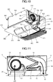
FIG. 11 illustrates a conventional ceiling-embedded air conditioner. 10 denotes to a main unit, and 20 denotes to a decorative panel having anintake port 21, and anoutlet port 23 provided withwind deflectors 22. Themain unit 10 is surrounded by ahousing 11 the top side and the lateral sides of which are made of steel plates. Provided inside themain unit 10 are asirocco fan 12 that sucks the air from theintake port 21 provided to thedecorative panel 20, afan casing 13 in which thesirocco fan 12 is housed, aheat exchanger 14 that has a V shape rotated by 90 degrees, and against which the wind coming out of thesirocco fan 12 and guided by thefan casing 13 blows, adrain pan 15 that collects dew drops formed on theheat exchanger 14, and anoutlet guide 16 that changes the direction of the airflow passed through theheat exchanger 14, from a horizontal direction to a downward direction, and that guides the air to theoutlet port 23 of thedecorative panel 20. -
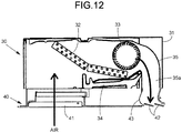
FIG. 12 illustrates another conventional ceiling-embedded air conditioner. 30 denotes to a main unit, and 40 denotes to a decorative panel having anintake port 41 and anoutput port 43 that is provided withwind deflectors 42. Themain unit 30 is surrounded by ahousing 31 the top side and the lateral sides of which are made of steel plates. Provided inside themain unit 30 are aheat exchanger 32 folded by an angle of 170 degrees or so, and diagonally positioned near theintake port 41 of thedecorative panel 40, asirocco fan 33 that sucks the air from theintake port 41 via theheat exchanger 32, adrain pan 34 that collects the dew drops formed on theheat exchanger 32, and anoutlet guide 35 that changes the direction of the airflow coming of thesirocco fan 33 from a horizontal direction to a downward direction, and that guides the air to an output port 44 of thedecorative panel 40. - The conventional ceiling-embedded air conditioners explained with reference to
FIGS. 11 and12 have a structure in which anoutlet ventilation path 16a extending along theoutlet guide 16 to theoutlet port 23 or anoutlet ventilation path 35a extending along theoutlet guide 35 to theoutput port 43 opens straight downwards, and the direction of the wind is changed to the frontward direction (toward the right inFIGS. 11 ,12 ) using the use of thewind deflectors 22 provided to theoutlet port 23 or thewind deflectors 42 provided to theoutput port 43. Therefore, as the wind deflectors 22, 24 change the direction of the wind, the direction is changed sharply, and the flow velocity of the wind drops quickly, and such sudden changes make it difficult to extend the reachable distance of the wind in the frontward direction. - An object of the present invention is to provide a ceiling-embedded air conditioner capable of alleviating a drop in the flow velocity of the outgoing air flow, and extending the reachable distance of the outgoing air flow in the frontward direction.
- In order to solve the above problems, the invention according to
claim 1 includes a main unit, and a decorative panel that has an intake port and an outlet guide tube and is mounted on a bottom surface of the main unit, wherein the main unit includes a box-shaped housing that has a top plate, a front plate, a rear plate, a left plate, and a right plate, a heat exchanger that is disposed inside the housing, a fan unit that is disposed inside the housing and includes a sirocco fan configured to collect air from the intake port and discharge the air from an outlet tube, and a drain pan that is configured to collects dew drops formed on the heat exchanger and has an outlet port opening through which the air discharged from the outlet tube of the sirocco fan passes toward the outlet guide tube of the decorative panel, the outlet guide tube of the decorative panel has: a top opening that communicates with the outlet tube of the sirocco fan through the outlet port opening of the drain pan, a bottom opening that faces a direction below the front plate of the main unit, and an outlet ventilation path that connects the top opening to the bottom opening and is curved, and a bottom end of the bottom opening protrudes more downwards than the decorative panel does. - The invention according to claim 2 is the ceiling-embedded air conditioner according to
claim 1, wherein in the decorative panel, the intake port is covered by a grill, and a portion of the decorative panel between the grill and the bottom end of the bottom opening of the outlet guide tube protrudes downwards. - The invention according to claim 3 is the ceiling-embedded air conditioner according to
claim 1 or 2, wherein an opening plane of the bottom opening of the outlet guide tube faces diagonally downwards toward a front. Advantageous Effects of Invention - According to the present invention, because the bottom opening of the outlet guide tube faces a direction below the front plate of the main unit, because the outlet ventilation path connecting the top opening to the bottom opening is curved, and because the bottom end of the bottom opening protrudes more downwards than the decorative panel does, the wind coming out of the fan unit is gently guided downwards toward the front, by the outlet ventilation path having a curved outlet guide tube, without changing the direction of the wind in up-and-down directions using up-and-down wind deflectors. Therefore, it is possible to alleviate a drop in the flow velocity of the outgoing air, and to extend its reachable distance in the frontward direction.
-
-
FIG. 1 is a schematic illustrating an installation of a ceiling-embedded air conditioner according to an embodiment of the present invention. -
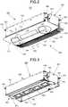
FIG. 2 is a perspective view illustrating the ceiling-embedded air conditioner inFIG. 1 . -
FIG. 3 is a perspective view of a main unit of the ceiling-embedded air conditioner illustrated inFIG. 2 . -
FIG. 4 is an exploded perspective view of the main unit inFIG. 3 . -
FIG. 5 is a perspective view of a top side of a drain pan. -
FIG. 6 is a perspective view of a reinforcement metal piece. -
FIG. 7 is a sectional view across A-A inFIG. 2 . -
FIG. 8 is a sectional view across B-B inFIG. 2 . -
FIG. 9 is a sectional view along C-C inFIG. 6 . -
FIG. 10 is a perspective view illustrating an A-A section inFIG. 2 . -
FIG. 11 is a general schematic illustrating a conventional ceiling-embedded air conditioner. -
FIG. 12 is a general schematic illustrating another conventional ceiling-embedded air conditioner. - A ceiling-embedded
air conditioner 100 according to an embodiment of the present invention will now be explained. This ceiling-embeddedair conditioner 100 is mounted on a ceiling T1 of the air-conditioned room R, as illustrated inFIG. 1 , and is connected to an outdoor unit, not illustrated, installed outdoor through a refrigerant line, to form a refrigerant circuit. The ceiling-embeddedair conditioner 100 includes a box-shapedmain unit 200 that is installed in a garret T2, and adecorative panel 300 that is mounted on the bottom surface of themain unit 200, in a manner exposed to the air-conditioned room R. Themain unit 200 has anelectrical equipment box 400 having a control board mounted on a side surface, as illustrated inFIG. 2 . -
Outlet guide tubes decorative panel 300. The outgoing direction of the wind in the up-and-down directions can be adjusted by adjusting the wind passing through the leftmostoutlet guide tube 310 using theoutlet guide tube 310 and an up-and-down wind deflector 311 rotating with a leftmostrotating plate 380; adjusting the wind passing through the centeroutlet guide tubes 320, 330 using a shared up-and-down wind deflector 321; and adjusting the wind passing through the rightmostoutlet guide tube 340 using theoutlet guide tube 340 and an up-and-down wind deflector 341 rotating with a rightmostrotating plate 390. Therotating plate 380 is provided rotatably toward the left by 90 degrees from the position illustrated inFIG. 2 , and therotating plate 390 is provided rotatably toward the right by 90 degrees from the position illustrated inFIG. 2 . - Behind the line along which the
outlet guide tubes bottom surface 370 of the decorative panel 300 (the surface facing the air-conditioned room R illustrated inFIG. 1 ), anintake port 350 having an elongated shape in a left-to-right direction is provided, and theintake port 350 is covered by agrill 360. Aprotruding portion 371 protruding downwards, in the manner to be described later, is provided between thegrill 360 and the up-and-down wind deflectors grill 360 and afront part 372 of thebottom surface 370 of thedecorative panel 300, and protrudes more downwards than thefront part 372 does. -
FIG. 3 illustrates a view of themain unit 200 with thedecorative panel 300 removed, in a direction looking up from below, andFIG. 4 illustrates an exploded view of themain unit 200 in the direction looking up from below. Themain unit 200 includes, in addition to theelectrical equipment box 400, ahousing 500 made of a steel plate, aheat exchanger 600, afan unit 700, adrain pan 800, and adrain pump 900 having anintake port 910 and adischarge port 920. - The
housing 500 has a box-like shape having atop plate 510 that has a rectangular shape, and afront plate 520, arear plate 530, aleft plate 540, and aright plate 550 that extend from the respective four sides of thetop plate 510. Theelectrical equipment box 400 illustrated inFIG. 2 is mounted on theright plate 550, and adrainpipe 551 is attached to the sameright plate 550. Twoattachment clamps 560 are mounted on each of theleft plate 540 and theright plate 550, on the side facing thetop plate 510. Themain unit 200 is installed in the garret T2, by having theattachment clamps 560 suspended from suspension bolts, not illustrated, that are fixed in the garret T2. - The
heat exchanger 600 is housed in thehousing 500, and includes afirst heat exchanger 610 disposed near thefront plate 520 of thehousing 500, and asecond heat exchanger 620 disposed near therear plate 530. Thefirst heat exchanger 610 is inclined in such a manner that the upper side thereof is positioned near thefront plate 520 of thehousing 500, and thesecond heat exchanger 620 is inclined in such a manner that the upper side thereof is positioned near therear plate 530 of thehousing 500. Theseheat exchangers top plate 510 of thehousing 500. A motorshaft support plate 630 supporting a motorrotational shaft 712, which will be described later, is attached to ends of theheat exchangers left plate 540, and a motorshaft support plate 640 supporting a motorrotational shaft 713, which will be described later, is attached to ends of theheat exchangers right plate 550. - The
fan unit 700 includes a double-shaft fan motor 710 having amotor mount 711, twoimpellors rotational shaft 712 of thefan motor 710, twoimpellors rotational shaft 713 of thefan motor 710, andfan casings 731 to 734 that cover therespective impellors 721 to 724. Each of thefan casings 731 to 734 includes atop mount 731a to 734a to be attached to thetop plate 510 of thehousing 500, an intake opening 731b to 734b provided on one side surface, and anoutlet tube 731c to 734c provided in a manner protruding downwards. Each pair of theimpellor 721 and thefan casing 731, theimpellor 722 and thefan casing 732, theimpellor 723 and the fan casing 7331, and theimpellor 724 and thefan casing 734 forms a sirocco fan. - The
drain pan 800 is made from aninsulator material 810 made of polystyrene foam. Thisinsulator material 810 has fouroutlet port openings 821 to 824 passing through atop surface 810a to abottom surface 810b thereof, provided in a manner arranged along a line. Thedrain pan 800 has a substantially rectangular shape having arear end 810c and afront end 810d thereof as its long sides, as illustrated inFIG. 5 . - The
top surface 810a of theinsulator material 810 is provided with agroove 833 that receives the dew drops formed on thesecond heat exchanger 620 and is formed between anouter wall 831 on the side of therear end 810c and aninner wall 832 on the rear side. Agroove 843 configured to receive the dew drops formed on thefirst heat exchanger 610 is formed between anouter wall 841 on the side of thefront end 810d, and aninner wall 842 on the front side. Agroove 853 is also provided between anouter wall 851 on the side of aright end 810e, and aninner wall 852 on the right side. Agroove 834 serving as a drain pan configured to receive the dew drops attached to the outside of thefan casings 731 to 734 is also provided between theinner wall 832 andside walls 821a to 824a of theoutlet port openings 821 to 824. Agroove 844 serving as a drain pan configured to receive the dew drops attached to the outside of thefan casings 731 to 734 is also provided between theinner wall 842 andside walls 821a to 824a of theoutlet port openings 821 to 824. Adrain tank 860 is provided at the rear right on thetop surface 810a of theinsulator material 810. Thegroove 833 and thegroove 853 are continuous to thedrain tank 860, and thegroove 843 is continuous to thegroove 853. In other words, the drain water collected into thegrooves drain tank 860. Thegrooves grooves - On the side of the
bottom surface 810b of theinsulator material 810, areinforcement metal piece 870 having the shape illustrated inFIG. 6 is mounted, by embedding. Thereinforcement metal piece 870 has along piece 871 corresponding to therear end 810c of thedrain pan 800, along piece 872 corresponding to thefront end 810d, ashort piece 873 connecting the left ends of thelong piece 871 and thelong piece 872 inFIG. 6 , ashort piece 874 connecting the right ends of thelong piece 871 and thelong piece 872 inFIG. 6 , andattachment pieces reinforcement metal piece 870 is a rectangular shape surrounding the outside of theoutlet port openings 821 to 824 provided to thedrain pan 800, with the rectangular shape delineated by thelong pieces short pieces reinforcement metal piece 870 in theinsulator material 810, thereinforcement metal piece 870 is positioned inside a mold for forming theinsulator material 810 in advance, and polystyrene foam is then caused to foam so that thereinforcement metal piece 870 is embedded therein. In this manner, thereinforcement metal piece 870 is integrated with theinsulator material 810 in such a manner that thelong piece insulator material 810, with theshort pieces attachment pieces - The
outlet guide tube 310 of thedecorative panel 300 is provided communicatively with the outlet port opening 821 of thedrain pan 800, and theoutlet guide tube 320 is provided communicatively with the outlet port opening 822 of thedrain pan 800. The outlet guide tube 330 is provided communicatively with the outlet port opening 823 of thedrain pan 800, and theoutlet guide tube 340 is provided communicatively with the outlet port opening 824 of thedrain pan 800. The up-and-down wind deflector 311 in the leftmostoutlet guide tube 310 and the up-and-down wind deflector 341 in the rightmostoutlet guide tube 340 are rotationally adjustable by an angle of 90 degrees, as mentioned earlier. - The
outlet guide tube 320 will now be explained as an example. As illustrated inFIG. 7 , theoutlet guide tube 320 has atop opening 322 that communicates with theoutlet tube 732c of thefan casing 732, on the outlet port opening 822 of thedrain pan 800, abottom opening 323 that is positioned facing diagonally downwards toward the front, and anoutlet ventilation path 324 that extends from thetop opening 322 to thebottom opening 323, and that is smoothly curved. The up-and-down wind deflector 321 shared with the outlet guide tube 330 is mounted on thebottom opening 323 serving as an outlet port opening. A right-and-leftwind deflector 325 for theoutlet guide tube 320 is also mounted on theoutlet ventilation path 324 on the upper rear portion. Abottom end 323a of thebottom opening 323 protrudes more downwards than thefront part 372 of thebottom surface 370 of thedecorative panel 300 does. The same type of the right-and-left wind deflector, not illustrated, as the right-and-leftwind deflector 325 is also mounted on an outlet ventilation path, not illustrated, in the outlet guide tube 330. Right-and-left wind deflectors, not illustrated, are also mounted on the leftmostoutlet guide tube 310 and the rightmostoutlet guide tube 340, respectively. The up-and-down wind deflectors rotating plate - Assembling of the ceiling-embedded
air conditioner 100 will now be explained by referring toFIG. 4 as appropriate. To begin with, thehousing 500 of themain unit 200 is placed on an assembly table with thetop plate 510 facing upwards, and the assembledheat exchangers top plate 510. - After positioning the assembled
fan unit 700 between theheat exchangers motor mount 711 of thefan motor 710 is fixed to thetop plate 510 with screws. The one motorrotational shaft 712 is then supported on the motorshaft support plate 630, and the other motorrotational shaft 713 is then supported on the motorshaft support plate 640. The top mounts 731a to 734a of therespective fan casings 731 to 734 are then screwed onto thetop plate 510. - At this time, as illustrated in
FIG. 4 , thefan unit 700 is placed nearer to thefirst heat exchanger 610 on the front side than to thesecond heat exchanger 620 on the rear side so that L1<L2 is established, denoting the distance between the center C1 of the motorrotational shafts fan unit 700 and a center C2 of thefirst heat exchanger 610 on the front side in the up-and-down direction as L1, and denoting the distance between C1 and a center C3 of thesecond heat exchanger 620 on the rear side in the up-and-down direction as L2. - The
drain pump 900 is then attached to the inner side of theright plate 550 of thehousing 500, and thedischarge port 920 is joined to thedrainpipe 551 illustrated inFIG. 3 . After aligning thesecond heat exchanger 620 with thegroove 833 provided on thetop surface 810a of thedrain pan 800, and aligning thefirst heat exchanger 610 with thegroove 843, thedrain pan 800 is pushed up from below so that thedrain pan 800 fits inside of thehousing 500, and theshort piece 873 of thereinforcement metal piece 870 is fixed to theleft plate 540 of thehousing 500 with screws, and theattachment pieces right plate 550. With thedrain pan 800 mounted in the manner described, therear end 810c faces a space S1, which will be described later, and thefront end 810d faces a space S2, which will also be described later. - As a result of the steps described above, the
outlet tubes 731c to 734c of the respective fourfan casings 731 to 734 in thefan unit 700 get inside of theside walls 821a to 824a of the fouroutlet port openings 821 to 824, respectively, on thetop surface 810a of thedrain pan 800, and theoutlet tubes 731c to 734c of therespective fan casings 731 to 734 come to communicate with theoutlet port openings 821 to 824, respectively, on thedrain pan 800. Furthermore, theintake port 910 of thedrain pump 900 is positioned inside thedrain tank 860 on thedrain pan 800. - Because the assembled
main unit 200 is packed separately from thedecorative panel 300, when the ceiling-embeddedair conditioner 100 is installed, the package is unpacked, and themain unit 200 is installed in the garret T2 by hanging themain unit 200 from a plurality of suspension bolts embedded in the garret T2. Thedecorative panel 300 is then attached from the side of the air-conditioned room R, as illustrated inFIG. 1 . Thetop opening 322 of theoutlet guide tube 320 provided on thedecorative panel 300 is then inserted into the outlet port opening 822 from thebottom surface 810b of thedrain pan 800, as illustrated inFIG. 7 , so that theoutlet guide tube 320 becomes communicative with theoutlet tube 732c of thefan casing 732. The remainingoutlet guide tubes outlet port openings drain pan 800, so that the remainingoutlet guide tubes outlet tubes fan casings decorative panel 300 is then fixed to thehousing 500 of themain unit 200 with screws, and a refrigerant line, a power line, a signal line, and the like, not illustrated, are connected thereto. - In the ceiling-embedded
air conditioner 100 assembled in the manner described above, as illustrated inFIG. 8 , the space S1 between thesecond heat exchanger 620 on the rear side and therear plate 530 becomes communicative with the space S2 between thefirst heat exchanger 610 on the front side and thefront plate 520 of thehousing 500 through a space S3 between thebottom surface 810b of thedrain pan 800 and thedecorative panel 300. This space S3 not only serves as a space where theoutlet guide tubes 310, 312 to 320, 326 to 340 are positioned, but also serves as a space where the outlet guide tubes are connected to each other. - Based on the above, in the ceiling-embedded
air conditioner 100 according to the embodiment, theoutlet guide tube 320 has thebottom opening 323 with a bottom end 232a thereof protruding more downwards than thefront part 372 of thebottom surface 370 of thedecorative panel 300 does, and thebottom opening 323 has an opening plane facing diagonally downwards toward the front. Furthermore, theoutlet ventilation path 324 is smoothly curved toward the direction below thefront plate 520. Therefore, theoutlet guide tube 320 is less likely cause volume loss in the air that therotating impellor 722 blows, and it becomes possible to extend the reachable distance of the outgoing air flow in a frontward direction with respect to the ceiling-embeddedair conditioner 100. The same is applicable to theoutlet guide tubes - The air collected from the
intake port 350 of thedecorative panel 300 reaches thesecond heat exchanger 620 through the space S1 provided between thesecond heat exchanger 620 on the rear side and therear plate 530. The air collected from theintake port 350 of thedecorative panel 300 reaches thefirst heat exchanger 610 on the front side via the space S3 and the space S2, the space S3 being formed between thebottom surface 810b of thedrain pan 800 and thedecorative panel 300 and between theoutlet guide tubes 310, 312 to 320, 326 to 340, the space S2 being formed between the front-sidefirst heat exchanger 610 and thefront plate 520. Therefore, a sufficient amount of air can be sent to thefirst heat exchanger 610, which is at a greater distance than thesecond heat exchanger 620 with respect to theintake port 350, and therefore, the same level of heat exchange be achieved by thefirst heat exchanger 610 as that achieved by thesecond heat exchanger 620, and hence, it becomes possible to improve the heat exchange efficiency of the ceiling-embedded heat exchangers. At this time, because thefirst heat exchanger 610 is inclined in such a manner that the upper side thereof is positioned near thefront plate 520 of thehousing 500, and thesecond heat exchanger 620 is inclined in such a manner that the upper side thereof is positioned near therear plate 530 of thehousing 500, and also because the air is collected into the spaces S1, S2 from below, the angle at which the direction of the incoming air is changed is increased from a right angle to a more gradual obtuse angle, so that the ventilation resistance is reduced, and the heat-exchange efficiency between the air and the refrigerant in the first andsecond heat exchangers second heat exchangers - Furthermore, as illustrated in
FIG. 7 , denoting the distance between the center C1 of the motorrotational shafts fan unit 700 and the center C2 of thefirst heat exchanger 610 in the up-and-down direction as L1, and denoting the distance between C1 and the center C3 of thesecond heat exchanger 620 in the up-and-down direction as L2, these distances are set so that L1<L2 is established. At this time, theoutlet tubes 731c to 734c of therespective fan casings 731 to 734 are configured to face straight downwards, that is, to face thedrain pan 800. Therefore, theoutlet tubes 731c to 734c do not hit thefirst heat exchanger 610 or thesecond heat exchanger 620. Based on the above, it is possible to achieve an arrangement in which thefan unit 700 is positioned nearer to thefirst heat exchanger 610 than to thesecond heat exchanger 620, and as a result, the volume of the air sucked into thefirst heat exchanger 610 positioned nearer to thefan unit 700 is increased. As a result, because the volume of the air sucked into thefirst heat exchanger 610 is set larger than that sucked into thesecond heat exchanger 620, compared with a configuration in which L1=L2, it becomes possible even for thefirst heat exchanger 610, which has a longer airflow path than that of thesecond heat exchanger 620, to achieve the same level of heat-exchange efficiency as that achieved by thesecond heat exchanger 620, and therefore, the balance is improved. In other words, by setting L1<L2, the volume of the air sucked into thefirst heat exchanger 610 is increased, and the balance of the heat-exchange efficiency between thefirst heat exchanger 610 and thesecond heat exchanger 620 is improved. Furthermore, if L2 is set in the same manner as that conventionally practiced, because thefirst heat exchanger 610 is positioned nearer to therear plate 530 of thehousing 500, it is possible to position thefront plate 520 of thehousing 500 nearer to therear plate 530, and the size of thehousing 500 in the front-and-back direction can be reduced. Furthermore, when a part of thefan casings 731 to 734 of thefan unit 700 on the side of thefirst heat exchanger 610 is brought into abutment against thefirst heat exchanger 610, the part of thefan casings 731 to 734 facing thefirst heat exchanger 610 may be provided with a flat profile, by cutting along the line D1 illustrated inFIG. 7 . - Furthermore, the
fan casings 731 to 734 in thefan unit 700 are positioned in such a manner that the side walls of theoutlet tubes 731c to 734c get inside of theside walls 821a to 824a of theoutlet port openings 821 to 824, respectively, provided to thedrain pan 800. Thedrain pan 800 has thegroove 834 on the side of theside walls 821a to 824a with respect to thegroove 833 for thesecond heat exchanger 620, and thegroove 844 on the side of theside walls 821a to 824a with respect to thegroove 843 for thefirst heat exchanger 610. Therefore, when dew drops become attached outside of thefan casings 731 to 734, the dew drops fall into and are received by thegrooves drain pan 800. In this manner, it is possible to prevent the dew drops from falling into the room by following theoutlet guide tubes 310, 312 to 320, 326 to 340 of thedecorative panel 300. Because only a slight amount of dew falls from thefan casings 731 to 734, thegrooves grooves - Furthermore, the
reinforcement metal piece 870 is mounted on thedrain pan 800. Thereinforcement metal piece 870 is integrated with thedrain pan 800 by embedding thereinforcement metal piece 870 in theinsulator material 810 of thedrain pan 800 during the manufacturing process of thedrain pan 800. Thisreinforcement metal piece 870 improves the strength of thedrain pan 800 itself. Furthermore, although a reinforcement plate has been conventionally used to support thedrain pan 800 from the bottom, because thereinforcement metal piece 870 is embedded in thedrain pan 800 on the side of thebottom surface 810b, and supports thedrain pan 800 from the bottom, such a reinforcement plate can be omitted. Furthermore, because theshort piece 873 and theattachment pieces reinforcement metal piece 870 are screwed onto thehousing 500, it is also possible to mount thedrain pan 800, as well as to reinforce thehousing 500, with these screws. -
- 100
- ceiling-embedded air conditioner
- 200
- main unit
- 300
- decorative panel
- 310, 312 to 320, 326 to 340
- outlet guide tube
- 322
- top opening
- 323
- bottom opening
- 311, 321, 341
- up-and-down wind deflector
- 350
- intake port
- 360
- grill
- 370
- bottom surface
- 380, 390
- rotating plate
- 400
- electrical equipment box
- 500
- housing
- 510
- top plate
- 520
- front plate
- 530
- rear plate
- 540
- left plate
- 550
- right plate
- 560
- attachment clamp
- 551
- drainpipe
- 600
- heat exchanger
- 610
- first heat exchanger
- 620
- second heat exchanger
- 630, 640
- motor shaft support plate
- 700
- fan unit
- 710
- fan motor
- 721 to 724
- impellor
- 731 to 734
- fan casing
- 731c to 734c
- outlet tube
- 800
- drain pan
- 810
- insulator
- 821 to 824
- outlet port opening
- 833, 834, 843, 844
- groove
- 860
- drain tank
- 870
- reinforcement metal piece
- 900
- drain pump
Claims (3)
- A ceiling-embedded air conditioner comprising:a main unit; anda decorative panel that has an intake port and an outlet guide tube and is mounted on a bottom surface of the main unit, whereinthe main unit includes:a box-shaped housing that has a top plate, a front plate, a rear plate, a left plate, and a right plate;a heat exchanger that is disposed inside the housing;a fan unit that is disposed inside the housing and includes a sirocco fan configured to collect air from the intake port and discharge the air from an outlet tube; anda drain pan that collects dew drops formed on the heat exchanger and has an outlet port opening through which the air discharged from the outlet tube of the sirocco fan passes toward the outlet guide tube of the decorative panel,the outlet guide tube of the decorative panel has: a top opening that communicates with the outlet tube of the sirocco fan through the outlet port opening of the drain pan; a bottom opening that faces a direction below the front plate of the main unit; and an outlet ventilation path that connects the top opening to the bottom opening and is curved, anda bottom end of the bottom opening protrudes more downwards than the decorative panel does.
- The ceiling-embedded air conditioner according to claim 1, wherein in the decorative panel,
the intake port is covered by a grill, and
a portion of the decorative panel between the grill and the bottom end of the bottom opening of the outlet guide tube protrudes downwards. - The ceiling-embedded air conditioner according to claim 1 or 2, wherein an opening plane of the bottom opening of the outlet guide tube faces diagonally downwards toward a front.
Applications Claiming Priority (2)
| Application Number | Priority Date | Filing Date | Title |
|---|---|---|---|
| JP2018069616A JP6635275B2 (en) | 2018-03-30 | 2018-03-30 | Ceiling-mounted air conditioner |
| PCT/JP2019/001788 WO2019187536A1 (en) | 2018-03-30 | 2019-01-22 | Ceiling-embedded air conditioner |
Publications (3)
| Publication Number | Publication Date |
|---|---|
| EP3779316A1 true EP3779316A1 (en) | 2021-02-17 |
| EP3779316A4 EP3779316A4 (en) | 2022-01-05 |
| EP3779316B1 EP3779316B1 (en) | 2024-10-30 |
Family
ID=68059005
Family Applications (1)
| Application Number | Title | Priority Date | Filing Date |
|---|---|---|---|
| EP19776797.3A Active EP3779316B1 (en) | 2018-03-30 | 2019-01-22 | Ceiling-embedded air conditioner |
Country Status (8)
| Country | Link |
|---|---|
| US (1) | US11898762B2 (en) |
| EP (1) | EP3779316B1 (en) |
| JP (1) | JP6635275B2 (en) |
| CN (1) | CN111902680B (en) |
| AU (1) | AU2019244621B2 (en) |
| ES (1) | ES2995016T3 (en) |
| PL (1) | PL3779316T3 (en) |
| WO (1) | WO2019187536A1 (en) |
Families Citing this family (2)
| Publication number | Priority date | Publication date | Assignee | Title |
|---|---|---|---|---|
| CN218955017U (en) | 2021-08-17 | 2023-05-02 | 广东积微科技有限公司 | Ceiling machine of two-sided even air-out |
| WO2025120798A1 (en) * | 2023-12-07 | 2025-06-12 | 三菱電機株式会社 | Ceiling embedded type air conditioning device |
Family Cites Families (24)
| Publication number | Priority date | Publication date | Assignee | Title |
|---|---|---|---|---|
| AU542354B2 (en) * | 1981-10-21 | 1985-02-21 | Mitsubishi Denki Kabushiki Kaisha | Ceiling mounted air conditioner |
| JPH05332568A (en) * | 1992-05-29 | 1993-12-14 | Hitachi Ltd | Ceiling embedded type air conditioning apparatus |
| JPH06221611A (en) * | 1993-01-25 | 1994-08-12 | Mitsubishi Electric Corp | Air-conditioner embedded in ceiling |
| JP2000213767A (en) * | 1999-01-27 | 2000-08-02 | Matsushita Electric Ind Co Ltd | Air conditioning unit |
| JP4527306B2 (en) * | 2001-03-16 | 2010-08-18 | 三菱電機株式会社 | Recessed ceiling air conditioner |
| JP3806883B2 (en) * | 2004-09-28 | 2006-08-09 | ダイキン工業株式会社 | Air conditioner |
| JP4747542B2 (en) * | 2004-09-28 | 2011-08-17 | ダイキン工業株式会社 | Blower and air conditioner |
| JP5194023B2 (en) | 2007-10-25 | 2013-05-08 | 東芝キヤリア株式会社 | Embedded ceiling air conditioner |
| JP4561926B2 (en) * | 2008-07-18 | 2010-10-13 | ダイキン工業株式会社 | Air conditioner indoor unit |
| CN103542460B (en) * | 2008-12-15 | 2016-01-20 | 大金工业株式会社 | Air conditioning indoor unit embedded in ceiling |
| CN102147130A (en) * | 2011-04-18 | 2011-08-10 | 广东美的制冷设备有限公司 | Indoor machine of two-tubular air conditioner |
| JP5464225B2 (en) * | 2012-03-26 | 2014-04-09 | ダイキン工業株式会社 | Air conditioner indoor unit |
| JP5447569B2 (en) * | 2012-03-26 | 2014-03-19 | ダイキン工業株式会社 | Air conditioner heat exchanger and air conditioner |
| JP5891190B2 (en) * | 2013-03-06 | 2016-03-22 | 日立アプライアンス株式会社 | Air conditioner indoor unit |
| KR102335152B1 (en) * | 2014-02-28 | 2021-12-06 | 삼성전자주식회사 | Indoor unit of air-conditioner and blade unit applying the same |
| JP6020543B2 (en) * | 2014-12-17 | 2016-11-02 | ダイキン工業株式会社 | Air conditioner indoor unit |
| EP3550218B1 (en) * | 2016-11-30 | 2020-09-16 | Mitsubishi Electric Corporation | Air conditioner indoor unit |
| JP2018119718A (en) * | 2017-01-24 | 2018-08-02 | 株式会社富士通ゼネラル | Embedded ceiling air conditioner |
| JP2018119714A (en) * | 2017-01-24 | 2018-08-02 | 株式会社富士通ゼネラル | Embedded ceiling air conditioner |
| CN208765230U (en) * | 2017-02-09 | 2019-04-19 | 三菱电机株式会社 | Ceiling embedded indoor unit and air conditioner of air conditioner |
| JP6716007B2 (en) * | 2017-02-23 | 2020-07-01 | 三菱電機株式会社 | Air conditioner |
| EP3617602B1 (en) * | 2017-04-24 | 2024-04-10 | Mitsubishi Electric Corporation | Indoor unit for air conditioner comprising a refrigerant-sensing device |
| CN111033144B (en) * | 2017-08-30 | 2021-08-10 | 夏普株式会社 | Indoor unit of air conditioner |
| KR102508191B1 (en) * | 2017-11-10 | 2023-03-09 | 삼성전자주식회사 | Air conditioner |
-
2018
- 2018-03-30 JP JP2018069616A patent/JP6635275B2/en active Active
-
2019
- 2019-01-22 PL PL19776797.3T patent/PL3779316T3/en unknown
- 2019-01-22 AU AU2019244621A patent/AU2019244621B2/en not_active Ceased
- 2019-01-22 EP EP19776797.3A patent/EP3779316B1/en active Active
- 2019-01-22 ES ES19776797T patent/ES2995016T3/en active Active
- 2019-01-22 US US17/040,178 patent/US11898762B2/en active Active
- 2019-01-22 WO PCT/JP2019/001788 patent/WO2019187536A1/en not_active Ceased
- 2019-01-22 CN CN201980021150.1A patent/CN111902680B/en active Active
Also Published As
| Publication number | Publication date |
|---|---|
| JP6635275B2 (en) | 2020-01-22 |
| EP3779316A4 (en) | 2022-01-05 |
| US20210010686A1 (en) | 2021-01-14 |
| JP2019178829A (en) | 2019-10-17 |
| EP3779316B1 (en) | 2024-10-30 |
| US11898762B2 (en) | 2024-02-13 |
| CN111902680B (en) | 2022-03-22 |
| WO2019187536A1 (en) | 2019-10-03 |
| AU2019244621B2 (en) | 2022-06-23 |
| CN111902680A (en) | 2020-11-06 |
| AU2019244621A1 (en) | 2020-10-22 |
| ES2995016T3 (en) | 2025-02-05 |
| PL3779316T3 (en) | 2025-03-31 |
Similar Documents
| Publication | Publication Date | Title |
|---|---|---|
| JP5587060B2 (en) | Built-in air conditioner | |
| JP3806883B2 (en) | Air conditioner | |
| JP2019203619A (en) | Ceiling-embedded air conditioner | |
| EP3779316B1 (en) | Ceiling-embedded air conditioner | |
| JP2016160780A (en) | Air conditioner | |
| JP5884069B2 (en) | Built-in air conditioner | |
| JP2019178831A (en) | Ceiling embedded type air conditioner | |
| JP7255080B2 (en) | Ceiling-mounted air conditioner | |
| EP2163831A1 (en) | Air conditioner | |
| CN100386569C (en) | Indoor unit of air conditioner | |
| CN102878623B (en) | The outdoor unit of air-conditioning device | |
| JP6923845B2 (en) | Duct type air conditioner | |
| JP7230334B2 (en) | Ceiling-mounted air conditioner | |
| JP4616607B2 (en) | Air conditioner | |
| KR102168581B1 (en) | Indoor unit of celling type air conditioner | |
| JP6737302B2 (en) | Ceiling embedded air conditioner | |
| JP6455225B2 (en) | Air conditioner | |
| JP6648593B2 (en) | Air conditioner | |
| JP3627673B2 (en) | Air conditioner outdoor unit | |
| JP7275478B2 (en) | Ceiling-mounted air conditioner | |
| JP2018204827A (en) | Duct type air conditioner | |
| JP7070085B2 (en) | Ceiling embedded air conditioner | |
| JP2017186944A (en) | Air conditioner | |
| JP2002357334A (en) | Air conditioner outdoor unit | |
| JP2018204828A (en) | Air conditioner |
Legal Events
| Date | Code | Title | Description |
|---|---|---|---|
| STAA | Information on the status of an ep patent application or granted ep patent |
Free format text: STATUS: THE INTERNATIONAL PUBLICATION HAS BEEN MADE |
|
| PUAI | Public reference made under article 153(3) epc to a published international application that has entered the european phase |
Free format text: ORIGINAL CODE: 0009012 |
|
| STAA | Information on the status of an ep patent application or granted ep patent |
Free format text: STATUS: REQUEST FOR EXAMINATION WAS MADE |
|
| 17P | Request for examination filed |
Effective date: 20201007 |
|
| AK | Designated contracting states |
Kind code of ref document: A1 Designated state(s): AL AT BE BG CH CY CZ DE DK EE ES FI FR GB GR HR HU IE IS IT LI LT LU LV MC MK MT NL NO PL PT RO RS SE SI SK SM TR |
|
| AX | Request for extension of the european patent |
Extension state: BA ME |
|
| DAV | Request for validation of the european patent (deleted) | ||
| DAX | Request for extension of the european patent (deleted) | ||
| A4 | Supplementary search report drawn up and despatched |
Effective date: 20211206 |
|
| RIC1 | Information provided on ipc code assigned before grant |
Ipc: F24F 13/32 20060101ALI20211130BHEP Ipc: F24F 13/06 20060101ALI20211130BHEP Ipc: F24F 1/0047 20190101ALI20211130BHEP Ipc: F24F 1/0022 20190101ALI20211130BHEP Ipc: F24F 13/20 20060101AFI20211130BHEP |
|
| GRAP | Despatch of communication of intention to grant a patent |
Free format text: ORIGINAL CODE: EPIDOSNIGR1 |
|
| STAA | Information on the status of an ep patent application or granted ep patent |
Free format text: STATUS: GRANT OF PATENT IS INTENDED |
|
| INTG | Intention to grant announced |
Effective date: 20240624 |
|
| GRAS | Grant fee paid |
Free format text: ORIGINAL CODE: EPIDOSNIGR3 |
|
| GRAA | (expected) grant |
Free format text: ORIGINAL CODE: 0009210 |
|
| STAA | Information on the status of an ep patent application or granted ep patent |
Free format text: STATUS: THE PATENT HAS BEEN GRANTED |
|
| AK | Designated contracting states |
Kind code of ref document: B1 Designated state(s): AL AT BE BG CH CY CZ DE DK EE ES FI FR GB GR HR HU IE IS IT LI LT LU LV MC MK MT NL NO PL PT RO RS SE SI SK SM TR |
|
| REG | Reference to a national code |
Ref country code: GB Ref legal event code: FG4D |
|
| REG | Reference to a national code |
Ref country code: CH Ref legal event code: EP |
|
| REG | Reference to a national code |
Ref country code: DE Ref legal event code: R096 Ref document number: 602019061174 Country of ref document: DE |
|
| REG | Reference to a national code |
Ref country code: IE Ref legal event code: FG4D |
|
| REG | Reference to a national code |
Ref country code: GR Ref legal event code: EP Ref document number: 20240402915 Country of ref document: GR Effective date: 20250120 |
|
| REG | Reference to a national code |
Ref country code: ES Ref legal event code: FG2A Ref document number: 2995016 Country of ref document: ES Kind code of ref document: T3 Effective date: 20250205 |
|
| REG | Reference to a national code |
Ref country code: LT Ref legal event code: MG9D |
|
| REG | Reference to a national code |
Ref country code: NL Ref legal event code: MP Effective date: 20241030 |
|
| PG25 | Lapsed in a contracting state [announced via postgrant information from national office to epo] |
Ref country code: IS Free format text: LAPSE BECAUSE OF FAILURE TO SUBMIT A TRANSLATION OF THE DESCRIPTION OR TO PAY THE FEE WITHIN THE PRESCRIBED TIME-LIMIT Effective date: 20250228 Ref country code: PT Free format text: LAPSE BECAUSE OF FAILURE TO SUBMIT A TRANSLATION OF THE DESCRIPTION OR TO PAY THE FEE WITHIN THE PRESCRIBED TIME-LIMIT Effective date: 20250228 Ref country code: HR Free format text: LAPSE BECAUSE OF FAILURE TO SUBMIT A TRANSLATION OF THE DESCRIPTION OR TO PAY THE FEE WITHIN THE PRESCRIBED TIME-LIMIT Effective date: 20241030 |
|
| PG25 | Lapsed in a contracting state [announced via postgrant information from national office to epo] |
Ref country code: FI Free format text: LAPSE BECAUSE OF FAILURE TO SUBMIT A TRANSLATION OF THE DESCRIPTION OR TO PAY THE FEE WITHIN THE PRESCRIBED TIME-LIMIT Effective date: 20241030 Ref country code: NL Free format text: LAPSE BECAUSE OF FAILURE TO SUBMIT A TRANSLATION OF THE DESCRIPTION OR TO PAY THE FEE WITHIN THE PRESCRIBED TIME-LIMIT Effective date: 20241030 |
|
| REG | Reference to a national code |
Ref country code: AT Ref legal event code: MK05 Ref document number: 1737207 Country of ref document: AT Kind code of ref document: T Effective date: 20241030 |
|
| PG25 | Lapsed in a contracting state [announced via postgrant information from national office to epo] |
Ref country code: BG Free format text: LAPSE BECAUSE OF FAILURE TO SUBMIT A TRANSLATION OF THE DESCRIPTION OR TO PAY THE FEE WITHIN THE PRESCRIBED TIME-LIMIT Effective date: 20241030 |
|
| PG25 | Lapsed in a contracting state [announced via postgrant information from national office to epo] |
Ref country code: NO Free format text: LAPSE BECAUSE OF FAILURE TO SUBMIT A TRANSLATION OF THE DESCRIPTION OR TO PAY THE FEE WITHIN THE PRESCRIBED TIME-LIMIT Effective date: 20250130 |
|
| PG25 | Lapsed in a contracting state [announced via postgrant information from national office to epo] |
Ref country code: LV Free format text: LAPSE BECAUSE OF FAILURE TO SUBMIT A TRANSLATION OF THE DESCRIPTION OR TO PAY THE FEE WITHIN THE PRESCRIBED TIME-LIMIT Effective date: 20241030 Ref country code: AT Free format text: LAPSE BECAUSE OF FAILURE TO SUBMIT A TRANSLATION OF THE DESCRIPTION OR TO PAY THE FEE WITHIN THE PRESCRIBED TIME-LIMIT Effective date: 20241030 |
|
| PG25 | Lapsed in a contracting state [announced via postgrant information from national office to epo] |
Ref country code: RS Free format text: LAPSE BECAUSE OF FAILURE TO SUBMIT A TRANSLATION OF THE DESCRIPTION OR TO PAY THE FEE WITHIN THE PRESCRIBED TIME-LIMIT Effective date: 20250130 |
|
| PG25 | Lapsed in a contracting state [announced via postgrant information from national office to epo] |
Ref country code: SM Free format text: LAPSE BECAUSE OF FAILURE TO SUBMIT A TRANSLATION OF THE DESCRIPTION OR TO PAY THE FEE WITHIN THE PRESCRIBED TIME-LIMIT Effective date: 20241030 |
|
| PG25 | Lapsed in a contracting state [announced via postgrant information from national office to epo] |
Ref country code: DK Free format text: LAPSE BECAUSE OF FAILURE TO SUBMIT A TRANSLATION OF THE DESCRIPTION OR TO PAY THE FEE WITHIN THE PRESCRIBED TIME-LIMIT Effective date: 20241030 |
|
| PG25 | Lapsed in a contracting state [announced via postgrant information from national office to epo] |
Ref country code: EE Free format text: LAPSE BECAUSE OF FAILURE TO SUBMIT A TRANSLATION OF THE DESCRIPTION OR TO PAY THE FEE WITHIN THE PRESCRIBED TIME-LIMIT Effective date: 20241030 |
|
| PG25 | Lapsed in a contracting state [announced via postgrant information from national office to epo] |
Ref country code: RO Free format text: LAPSE BECAUSE OF FAILURE TO SUBMIT A TRANSLATION OF THE DESCRIPTION OR TO PAY THE FEE WITHIN THE PRESCRIBED TIME-LIMIT Effective date: 20241030 |
|
| PG25 | Lapsed in a contracting state [announced via postgrant information from national office to epo] |
Ref country code: SK Free format text: LAPSE BECAUSE OF FAILURE TO SUBMIT A TRANSLATION OF THE DESCRIPTION OR TO PAY THE FEE WITHIN THE PRESCRIBED TIME-LIMIT Effective date: 20241030 |
|
| PG25 | Lapsed in a contracting state [announced via postgrant information from national office to epo] |
Ref country code: CZ Free format text: LAPSE BECAUSE OF FAILURE TO SUBMIT A TRANSLATION OF THE DESCRIPTION OR TO PAY THE FEE WITHIN THE PRESCRIBED TIME-LIMIT Effective date: 20241030 |
|
| REG | Reference to a national code |
Ref country code: DE Ref legal event code: R097 Ref document number: 602019061174 Country of ref document: DE |
|
| REG | Reference to a national code |
Ref country code: CH Ref legal event code: PL |
|
| PLBE | No opposition filed within time limit |
Free format text: ORIGINAL CODE: 0009261 |
|
| STAA | Information on the status of an ep patent application or granted ep patent |
Free format text: STATUS: NO OPPOSITION FILED WITHIN TIME LIMIT |
|
| PG25 | Lapsed in a contracting state [announced via postgrant information from national office to epo] |
Ref country code: SE Free format text: LAPSE BECAUSE OF FAILURE TO SUBMIT A TRANSLATION OF THE DESCRIPTION OR TO PAY THE FEE WITHIN THE PRESCRIBED TIME-LIMIT Effective date: 20241030 |
|
| PG25 | Lapsed in a contracting state [announced via postgrant information from national office to epo] |
Ref country code: LU Free format text: LAPSE BECAUSE OF NON-PAYMENT OF DUE FEES Effective date: 20250122 Ref country code: MC Free format text: LAPSE BECAUSE OF FAILURE TO SUBMIT A TRANSLATION OF THE DESCRIPTION OR TO PAY THE FEE WITHIN THE PRESCRIBED TIME-LIMIT Effective date: 20241030 |
|
| 26N | No opposition filed |
Effective date: 20250731 |
|
| PG25 | Lapsed in a contracting state [announced via postgrant information from national office to epo] |
Ref country code: BE Free format text: LAPSE BECAUSE OF NON-PAYMENT OF DUE FEES Effective date: 20250131 |
|
| PG25 | Lapsed in a contracting state [announced via postgrant information from national office to epo] |
Ref country code: CH Free format text: LAPSE BECAUSE OF NON-PAYMENT OF DUE FEES Effective date: 20250131 |
|
| REG | Reference to a national code |
Ref country code: BE Ref legal event code: MM Effective date: 20250131 |
|
| PG25 | Lapsed in a contracting state [announced via postgrant information from national office to epo] |
Ref country code: IE Free format text: LAPSE BECAUSE OF NON-PAYMENT OF DUE FEES Effective date: 20250122 |
|
| PGFP | Annual fee paid to national office [announced via postgrant information from national office to epo] |
Ref country code: GB Payment date: 20260121 Year of fee payment: 8 |
|
| PGFP | Annual fee paid to national office [announced via postgrant information from national office to epo] |
Ref country code: ES Payment date: 20260217 Year of fee payment: 8 |
|
| PGFP | Annual fee paid to national office [announced via postgrant information from national office to epo] |
Ref country code: DE Payment date: 20260120 Year of fee payment: 8 |
|
| PGFP | Annual fee paid to national office [announced via postgrant information from national office to epo] |
Ref country code: IT Payment date: 20260130 Year of fee payment: 8 |
|
| PGFP | Annual fee paid to national office [announced via postgrant information from national office to epo] |
Ref country code: FR Payment date: 20260121 Year of fee payment: 8 |
|
| PGFP | Annual fee paid to national office [announced via postgrant information from national office to epo] |
Ref country code: GR Payment date: 20260119 Year of fee payment: 8 Ref country code: PL Payment date: 20260112 Year of fee payment: 8 |