EP3778048B1 - Machine d'usinage pour pièces de matériau plat dotée d'une unité de pose et procédé correspondant - Google Patents
Machine d'usinage pour pièces de matériau plat dotée d'une unité de pose et procédé correspondant Download PDFInfo
- Publication number
- EP3778048B1 EP3778048B1 EP19191932.3A EP19191932A EP3778048B1 EP 3778048 B1 EP3778048 B1 EP 3778048B1 EP 19191932 A EP19191932 A EP 19191932A EP 3778048 B1 EP3778048 B1 EP 3778048B1
- Authority
- EP
- European Patent Office
- Prior art keywords
- unit
- flat material
- processing machine
- material part
- processing
- Prior art date
- Legal status (The legal status is an assumption and is not a legal conclusion. Google has not performed a legal analysis and makes no representation as to the accuracy of the status listed.)
- Active
Links
- 239000000463 material Substances 0.000 title claims description 66
- 238000000034 method Methods 0.000 title claims description 17
- 238000003780 insertion Methods 0.000 claims description 20
- 230000001154 acute effect Effects 0.000 claims description 4
- 238000003754 machining Methods 0.000 claims description 3
- 238000005452 bending Methods 0.000 description 26
- 230000037431 insertion Effects 0.000 description 18
- 239000002184 metal Substances 0.000 description 13
- 230000008569 process Effects 0.000 description 12
- 230000007246 mechanism Effects 0.000 description 11
- 230000008901 benefit Effects 0.000 description 3
- 238000009957 hemming Methods 0.000 description 3
- 239000000243 solution Substances 0.000 description 3
- 230000002787 reinforcement Effects 0.000 description 2
- 230000008878 coupling Effects 0.000 description 1
- 238000010168 coupling process Methods 0.000 description 1
- 238000005859 coupling reaction Methods 0.000 description 1
- 238000005520 cutting process Methods 0.000 description 1
- 230000001419 dependent effect Effects 0.000 description 1
- 238000006073 displacement reaction Methods 0.000 description 1
- 238000004519 manufacturing process Methods 0.000 description 1
- 239000011159 matrix material Substances 0.000 description 1
- 238000003032 molecular docking Methods 0.000 description 1
- 238000003860 storage Methods 0.000 description 1
Images


Classifications
-
- B—PERFORMING OPERATIONS; TRANSPORTING
- B21—MECHANICAL METAL-WORKING WITHOUT ESSENTIALLY REMOVING MATERIAL; PUNCHING METAL
- B21D—WORKING OR PROCESSING OF SHEET METAL OR METAL TUBES, RODS OR PROFILES WITHOUT ESSENTIALLY REMOVING MATERIAL; PUNCHING METAL
- B21D5/00—Bending sheet metal along straight lines, e.g. to form simple curves
- B21D5/04—Bending sheet metal along straight lines, e.g. to form simple curves on brakes making use of clamping means on one side of the work
- B21D5/042—With a rotational movement of the bending blade
-
- B—PERFORMING OPERATIONS; TRANSPORTING
- B21—MECHANICAL METAL-WORKING WITHOUT ESSENTIALLY REMOVING MATERIAL; PUNCHING METAL
- B21D—WORKING OR PROCESSING OF SHEET METAL OR METAL TUBES, RODS OR PROFILES WITHOUT ESSENTIALLY REMOVING MATERIAL; PUNCHING METAL
- B21D43/00—Feeding, positioning or storing devices combined with, or arranged in, or specially adapted for use in connection with, apparatus for working or processing sheet metal, metal tubes or metal profiles; Associations therewith of cutting devices
- B21D43/003—Positioning devices
-
- B—PERFORMING OPERATIONS; TRANSPORTING
- B21—MECHANICAL METAL-WORKING WITHOUT ESSENTIALLY REMOVING MATERIAL; PUNCHING METAL
- B21D—WORKING OR PROCESSING OF SHEET METAL OR METAL TUBES, RODS OR PROFILES WITHOUT ESSENTIALLY REMOVING MATERIAL; PUNCHING METAL
- B21D43/00—Feeding, positioning or storing devices combined with, or arranged in, or specially adapted for use in connection with, apparatus for working or processing sheet metal, metal tubes or metal profiles; Associations therewith of cutting devices
- B21D43/02—Advancing work in relation to the stroke of the die or tool
- B21D43/04—Advancing work in relation to the stroke of the die or tool by means in mechanical engagement with the work
- B21D43/10—Advancing work in relation to the stroke of the die or tool by means in mechanical engagement with the work by grippers
- B21D43/11—Advancing work in relation to the stroke of the die or tool by means in mechanical engagement with the work by grippers for feeding sheet or strip material
-
- B—PERFORMING OPERATIONS; TRANSPORTING
- B21—MECHANICAL METAL-WORKING WITHOUT ESSENTIALLY REMOVING MATERIAL; PUNCHING METAL
- B21D—WORKING OR PROCESSING OF SHEET METAL OR METAL TUBES, RODS OR PROFILES WITHOUT ESSENTIALLY REMOVING MATERIAL; PUNCHING METAL
- B21D43/00—Feeding, positioning or storing devices combined with, or arranged in, or specially adapted for use in connection with, apparatus for working or processing sheet metal, metal tubes or metal profiles; Associations therewith of cutting devices
- B21D43/02—Advancing work in relation to the stroke of the die or tool
- B21D43/18—Advancing work in relation to the stroke of the die or tool by means in pneumatic or magnetic engagement with the work
-
- B—PERFORMING OPERATIONS; TRANSPORTING
- B21—MECHANICAL METAL-WORKING WITHOUT ESSENTIALLY REMOVING MATERIAL; PUNCHING METAL
- B21D—WORKING OR PROCESSING OF SHEET METAL OR METAL TUBES, RODS OR PROFILES WITHOUT ESSENTIALLY REMOVING MATERIAL; PUNCHING METAL
- B21D5/00—Bending sheet metal along straight lines, e.g. to form simple curves
- B21D5/002—Positioning devices
Definitions
- the present invention relates to a processing machine for flat material parts, comprising a machine frame, a lower beam, an upper beam, at least one processing tool assigned to the lower beam or upper beam and held on the machine frame, a control unit for controlling a processing sequence with the processing tools, an infeed table on which the Flat material part can be placed for positioning in the processing machine, and a placement unit for predetermined positioning of the flat material part on the feed table, wherein the feed table can be moved back and forth from a parking position in an extension direction into a loading and unloading position and wherein the placement unit has a plurality of Has suction cup units with which the flat material part can be picked up and positioned by the feed table, and it relates to a method for this.
- a processing machine for flat material parts with a loading unit is from EP 3 208 008 A1 known to the applicant.
- This placement unit makes it possible to improve, in particular to speed up, the feeding process of the placed flat material part.
- the loading unit here is a turning unit, in which a group of suction cups are each arranged between individual sections of the subdivided feed table and rotate the workpiece about an axis parallel to the bending axis, which bending axis is swung out from below the feed table above the feed table, the suction cups being attached to arms arranged transversely to the bending axis.
- the arms have a predetermined length in order to be able to grip the flat material part from behind and turn it over.
- U.S. 2016/107847 A1 shows a handling device for a folding machine.
- the part to be bent can be gripped on one of its flat sides by pulling forces acting on one side of the flat side at several successive points in the longitudinal direction, after which the holding unit in turn can be pivoted relative to a pivotable carrier unit about a first pivot axis parallel to the longitudinal direction, the pivotable carrier unit pivotable relative to a pivotable support base about a second pivot axis parallel to the first pivot axis, and wherein the pivotable support base is movable in a direction transverse to the second pivot axis by a support base moving unit.
- WO 97/32677 A1 shows a device for bending a metal sheet, comprising a frame, a stationary lower beam with a lower clamp, a movable upper beam with an upper clamp, the clamps each having a clamping surface for clamping a metal sheet in a working position, a lower bending beam and a Upper bending beam for bending a clamped metal sheet upwards or downwards, the bending beams being mounted on both sides in a carrier plate so that they can rotate about a corresponding axis, the carrier plates being movably mounted in the frame in such a way that the lower or upper bending beam is in can be moved to a working position in which its axis lies essentially in the plane of the clamping surface of the lower or upper clamp.
- a device for holding the sheet metal the holding device being provided with a substantially C-shaped frame with a carriage which is reciprocable on a carriage bed between a front and a rear position, the legs of the C- shaped frame respectively carry a lower and an upper disc suitable for engagement with a sheet metal in a working position.
- the legs of the C-shaped frame In the forward position of the carriage, the legs of the C-shaped frame extend between the top and bottom beams such that the bottom and top discs abut the clamps.
- WO 93/16822 A1 relates to a press brake having bending devices with bending rods and gripping devices mounted on a fixed lower jaw and a movable upper jaw.
- the flexures are attached to the jaws by spatial mechanisms, preferably ball joint couplings, and positioned longitudinally by mechanically or hydraulically actuated displacement devices.
- a transfer table is arranged to the side of the processing machine in a parallel plane and higher than the level specified by the infeed table and the loading unit comprises a side insertion unit which is fastened to an upper part of the machine frame and between a lower part and the upper part of the machine frame within the cheeks has a side insertion rail, wherein the suction cup units mounted on a frame component can be moved transversely to the processing tool or tools for a feed movement of the flat material part in the direction of the processing edge of the flat component predetermined by the processing tool or tools along the side insertion rail, a loading movement can be carried out via a rail pivotably connected to the upper part be accomplished, thereby allowing the lifting of the flat component from a loading table.
- a free space is provided between the transfer table and the feed table as a parking space for the placement unit, so that the processing machine can carry out the clamping movement of the cheeks necessary for the folding movement of a flat component without this placement unit spatially impeding such a movement.
- the placement unit is used as a side shift unit combined with a turning unit, so that one person feeds flat components to the machine and can turn them alone or not remove them from the machine after processing is complete.
- the placement unit is designed as a turning unit, which is mounted on the axis of movement associated with the processing tool or tools outside the associated cheek for a similar pivoting movement, results in several advantages.
- an existing movement axis is used for this placement unit, which works as a turning unit, so that no further elements are necessary.
- the feature "outside" an associated cheek also means that the mechanism, for example a parallelogram mechanism for moving the processing cheek, is arranged on the side of the cheeks opposite the pivot axis of the upper part and lower part, so that this mechanism does not have to open the upper part too much for the turning process requires.
- the suction cups of the placement unit are directly connected to the movement control, for example a parallelogram mechanism, of the processing tools, so that only a corresponding drive has to be provided via the sections of the processing machine.
- the suction cups can be mounted in a row on a frame. It is also possible two Provide rows of suction cups.
- the plane of the suction cups forms an acute angle with the horizontal plane of the feed table, in particular an angle between 70 and 85 degrees.
- the infeed table between the lower beam and the upper beam can advantageously be moved out in order to pick up a turned flat component after the suction cups have been released.
- the flat component turned over 95 to 110 degrees can also slide down onto a shelf provided below by releasing the suction cups.
- a further feed can be realized by the placement unit on the upper or lower processing tool if the flat component is placed in the parking position of the upper beam or the lower beam on the then activated suction cups and by pivoting downwards or upwards the flat component placed in this way on the moving infeed table is deposited, so that then, in particular after the retraction table has returned and the flat component has been aligned, processing by the bending tools begins.
- the function of the two placement units i.e. the side insertion unit and the turning unit, is that they feed the flat component from the outside into the interior without having to open the clamping cheeks very far, which takes a certain amount of time with the processing machines.
- the complexity of the machines is kept low by attaching the corresponding holding devices, suction cups, to frames which are attached to existing pivoting axes of the machine, so that the costs are kept low.
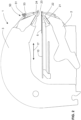
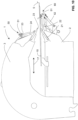
- the 1 shows a perspective view of a processing machine 1 according to exemplary embodiments of the invention. More precisely, two sections of a processing machine 1 with their upper parts 3 and lower parts 2, which are arranged on a transverse frame 4. Processing machines 1 with four, six or 8 sections are customary, in which case a feeding and turning unit 50 is particularly advantageous due to the length and weight of the flat component 5 to be turned.
- the frame 4 runs in a direction of the double arrow 7, which direction is also the direction of the bending edges that can be produced with the processing machine 1. This direction runs transversely to the feed direction 17.
- the one in the 1 The section shown furthest to the left is the foremost section in front of a set-up area 20.
- a lay-on unit 70 is shown in the form of a side-insertion unit, which is associated with FIG Figures 13 to 22 is explained.
- This placement unit 70 is used together with a transfer table 80 with stops 12 .
- the upper part 3 is also referred to as the upper machine part and the lower part 2 as the lower machine part of such a sheet metal bending machine. These are arranged so as to be movable relative to one another perpendicularly to a feed direction 17 of a workpiece 5 to be bent.
- the upper parts 3 and lower parts 2 can be driven and articulated in many ways, especially after EP 3 403 738 A1 the applicant.
- the processing machine 1 also does not have to be a double bending unit that has a lower processing tool 22 and an upper processing tool 24, as here in 1 shown, has. It can also be a single processing tool, which is assigned to the feed and turning unit 50 as a placement unit.
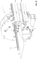
- the Figures 2 to 12 show here a double bender with two placement units 50 and 60, which are assigned to the two processing tools 22 and 24.
- the feed unit 50 comprises a series of suction cups 51 connected to a pneumatically operated vacuum source, this connection being controlled, for example, via hydraulically activatable valves.
- the feed unit 50 or the suction cups 51 of this are attached to a frame component 53 to which the processing tool 24 is attached directly or indirectly.
- the processing tool 24 is connected via an in 4 shown movable parallelogram mechanism 52 articulated on the upper part 3 and the upper beam 23.
- the processing tool 24 is already arranged in relation to the upper part 3 and the upper beam 23 in such a way that the processing tip of the processing tool 24 is in the extension direction of the Feed table 10 is arranged, which coincides with the direction of the plane defined by the surface of the underside of the suction cups 51, which direction in the side view of FIG 6 is specified by the sheet 5.
- the 6 shows the feed unit 50 after the placement of the flat component 5, before it after 7 is placed on the infeed table 10 and is then brought into the machine 1 as a feeding step by retracting the infeed table 10 in order to be advanced in the direction 17 in a predetermined manner after striking the depth stops between sections of the infeed table for processing.
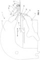
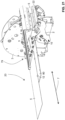
- the Figures 2 to 8 show in a sequence the sequence of movements when using this placement unit 50 with its additional function as an upper turning unit. while showing 2 a schematic side view of essential parts of a processing machine 1 with an infeed table 10 and the placement unit 50 in a rest position.
- the upper part 3 is slightly open compared to the lower part 2.
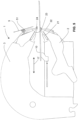
- the 3 shows a schematic side view of the processing machine 1 1 with a pushed-out feed table 10 on which the sheet metal 5 to be machined or already machined is located.
- the laying-on unit 50 is in a rest position.
- the 4 shows a schematic side view of the processing machine 1 1 with a feed table 10 pushed out and the placement unit 50 on the flat material part 5 in a receiving position.
- the upper processing tool 24 is pivoted as for a hemming process, except that the upper part 3 of the processing machine 1 is slightly open in relation to the lower part. This opening only needs to be opened slightly so that the processing tip of the upper processing tool 24 remains securely above the feed table 10 .
- the processing tool 24 is pivoted with the parallelogram mechanism 52 on the holder 53 outside the upper part 3, so that the suction cup 51 shown (from a row of suction cups 51 arranged parallel to the processing tool 24 in direction 7) is placed on the flat material part 5 lowered and supported on this, so that the flat material part 5 adheres to the suction cups 51 by a downstream suction of air located inside the suction cup 51 .
- a negative pressure is usually generated pneumatically and applied to the suction cups 51 via hydraulically actuated valves, which negative pressure is then constantly maintained.
- the figure 5 shows a schematic side view of the processing machine 1 1 with a pushed-out infeed table 10 and the laying-on unit 50 with received flat material part 5, the laying-on unit 50 returning to the rest position. This position of figure 5 is maintained in the vacuum from the 4 achieved by returning the machining tool 24 to its starting position.
- the 6 shows a schematic side view of the processing machine 1 with a pushed-out feed table 10 and the loading unit 50 with the feed table 10 lowered flat material part 5.
- a negative pressure / vacuum to represent the 6 was reduced via a valve control (lower negative pressure) in such a way that the dead weight of the flat material part 5 made it possible to lower it onto the feed table 10 .
- the flat material part 5 forms in the side view of 6 with the inward part of the feed table 10 an acute angle in the range between 70 and 85 degrees.
- the reference number 54 shows a reinforcement profile, which is arranged on the processing tool in direction 7 depending on the required expenditure of force.
- the 7 shows a schematic side view of the processing machine 1 1 with a pushed-out feed table 10 and the placement unit 50 with the flat material part 5 released and sliding onto the feed table 10; just before the flat material part 5 comes to rest fully on the feed table 10 .
- the 8 shows a schematic side view of the processing machine 1 1 with a partially retracted feed table 10 and now facing it 2 turned flat material part 5.
- a full turn has been achieved.
- the flat material part 5 can alternatively also be lowered directly to the ground or to a carriage arranged in front of the processing machine 1 .
- the Figures 9 to 12 show in a sequence the sequence of movements when using the placement unit 60, which is designed here as a lower turning unit. while showing 9 a schematic side view of essential parts of a processing machine 1 with an infeed table 10 and the placement units 50 and 60 in a rest position.
- the upper part 3 is slightly open compared to the lower part 2.
- the flat component 5 has already been machined on both side ends and has an “S” shape in each case in the cross section shown.
- An upper lay-up unit 50 and a lower lay-up unit 60 are shown, only the lower lay-up unit 60 being used here in sequence.
- This is also provided with corresponding suction cups 51 which are mounted on a frame part 53 which is firmly connected to the lower processing tool 22 .
- the 10 shows a schematic side view of the processing machine 1 9 with a pushed-out feed table 10 on which the sheet metal 5 already processed here lies.
- the upper lay-up unit 50 is in a rest position and will remain so throughout the sheet 5 turning operation.
- the turning process is carried out here by a lower placement unit 60 which is attached to the lower processing tool 22 .
- the lower processing tool 22 is pivoted as for a hemming process, except that the upper part 3 of the processing machine 1 is slightly open in relation to the lower part 2 . This opening only needs to be slightly open so that the machined flat component 5 can be safely pushed through on the feed table 10 between the cheeks 21 and 23 .
- the lower processing tool 22 is pivoted with the parallelogram mechanism 52 on the holder 53 outside the lower part 2, so that the suction cup 51 shown (from a row of suction cups 51 arranged parallel to the processing tool 22 in direction 7) moves from below the flat material part 5 applies, so that the flat material part 5 adheres to the suction cups 51 by subsequent suction of air located inside the suction cup 51 .
- the part of the suction cup 51 lying against the flat material part 5 is shown in the side view 10 covered by the feed table 10.
- the feed table 10 is not a continuous surface but has slots in the direction of the double arrow 17 at least at the locations of the suction cups 51, through which it extends from below the flat material part 5 can be created and through which the feed table 10 can be moved in and out in the direction of this double arrow 17 .
- the 11 shows a schematic side view of the processing machine 1 9 with a retracted feed table 10 and the laying-on unit 60 with the flat material part 5 that has been picked up and carried by it, before the laying-on unit 60 returns to the rest position.
- the one in the 11 The illustrated end position of the parallelogram mechanism 52 goes beyond the fold position of the lower processing tool 22 and also leads beyond the horizontal as alignment of the front end surface of the suction cups 51. Therefore, the free edge of the flat component 5 pointing away from the processing machine 1 (as far as the main orientation of the flat component 5 is concerned) is arranged higher relative to the base of the processing machine 1 than the end of the flat component 5 near the suction cup.
- the 12 shows a schematic side view of the processing machine 1 9 with the previously pivoted out lower laying unit 60 in the rest position but with activated suction cups 51 with it still held flat material part 5 over a tray 11. From the 11 Starting from this, the lower placement unit 60 is pivoted back so that the lower retaining cheek 21 forms the lower edge opposite the upper retaining cheek 23 and the flat material part 5 held on the suction cups 51 is pivoted downwards.
- the lower placement unit 60 acts as a turning unit and turns the flat material part 5 in relation to its position in z. B. 9 and then places it on tray 11.
- the lower placement unit can also be designed as a feed unit when in the position of the 12 the (then still unprocessed) flat component 5 is pressed against the row of suction cups and then the suction cups 51 with their parallelogram mechanism backwards, so to speak 11 be moved in order to then first correctly position the flat component for the folding processes described above after the feed table 12 has been pushed underneath.
- the arrangement of the lower and upper positioning units 50 and 60 is fixed to the associated bending tools 24 or 22 or on an axis parallel to their pivot axis, which is also an axis parallel to the axis of movement of the upper part 3 (and if the lower part 2 can be pivoted) or parallel to the axis of movement of the lower part 3 allows faster and safer turning of the flat component or faster conveyance of the same from the bending machine. Because these units act outside of the upper part 3 and lower part 2, this does not need to be opened that far, which saves further time.
- the angular relationships for the turning units 50 and 60 are easy to achieve an angle of over 90 degrees for effective turning is easier and can be achieved by using the parallelogram mechanism 52 that is already present for bending, which means one movement axis less.
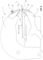
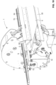
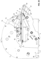
- the 13 shows a perspective view with essential parts of a processing machine 1 according to an embodiment of the invention.
- the feed table 10 is in the retracted position between the upper part 3 and the lower part 2, only a section of which is shown here. This section shown is the foremost section in front of a set-up area 20, which has a transfer table 80, not shown here.
- a loading unit runs transversely between the upper part 3 and the lower part 2 as a side insertion unit 70 which has a side insertion rail 72 under which a frame component 73 is arranged such that it can be moved in direction 7 .
- a plurality of suction cups 51 are arranged on the frame component 73, with which a flat component 5 can be picked up laterally outside of the processing machine 1 by the set-up table 80 mentioned. It has already happened here.
- the suction cups 51 correspond to the suction cups of the other embodiment with a corresponding, advantageously hydraulic control of valves and a permanently operated negative pressure source.
- the frame component 73 and thus the side insertion rail 72 is firmly connected to the upper part 3 .
- a stationary transfer table 80 with stops 12 is provided to reach the flat component 5 for insertion into the processing machine 1. These stops are in FIGS 1 , 19 and 21 only shown arranged forward. Lateral stops are not necessary since the position of the flat component 5 in the direction of the arrow 7 is not critical, because the cutting length of the bending machine 1 always far exceeds the length of the flat component 5 .
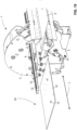
- the 14 shows a schematic side view of the processing machine 1 13 with the placement unit 70 in the pickup position with activated nine suction cups 51 with the flat component 5 picked up.
- 15 shows a schematic side view of the processing machine 1 13 with the placement unit in the insertion movement of the recorded flat component 5, the upper part 3 being slightly open, so that the flat component 5 is slightly inclined relative to the loading table 10.
- the 15 shows the insertion movement so that it is a state timed after the 14 shows. It's with her too 16 to recognize the a perspective view of the situation of 15 with the retracting placement unit 70, the flat component 5 that has been sucked in being moved in the direction of the double arrow 7 (here to the right) by the suction cups 51 and being moved further.
- the upper part is opened slightly, whereby the insertion rail is raised and tilted about the same axis of rotation, so that the flat component 5 picked up is lifted off the transfer table 80 and then moved by the frame component 73 along the side insertion rail 72 in the insertion direction of the double arrow 7 , until well after the presentation of the 16 the entire flat component 5 has been moved into the processing machine 1 until it is positioned between the cheeks 21 and 22 .
- the 17 shows a schematic side view of the processing machine 1 13 with the placement unit 70 after releasing the suction cups 51 with the flat component 5 lowered, whereby this protrudes from the front of the machine 1.
- 18 a perspective view of the situation of the processing machine 1 chronologically 17 , wherein the frame component 73 has been pulled back laterally on the side insertion rail 72 of the placement unit 70, while the metal sheet between the cheeks 22, 24 protrudes from the machine 1 at the front.
- 20 shows a schematic side view of the processing machine 1 19 .
- FIGS 17 to 20 show that after letting go of the flat component 5, the flat component 5 can be advanced with precise positioning without the use of the infeed table 10 by depth stops (not shown here), which are located between segments of the feed table 10 divided in the direction of the double arrow, in order to then fold the flat component 5 allow.
- depth stops not shown here
- For the frame member 73 is moved out laterally, as the 18 shows.
- the 19 shows the position of the frame component 73 to the side next to the foremost section of the processing machine 1, but in the direction of the double arrow 7 behind the transfer table 80, i.e.
- FIG. 21 shows a perspective view of the machine 1 during a folding process of a first flat component 5, the side insertion unit being the placement unit 70 in the parking position and a second flat component being placed on the transfer table 80 and pushed against the stops 12; and 22 shows a schematic side view of the processing machine 21 with the laying unit 70 in the parking position, with the two flat members 5, one which is bent over in its front portion and the other which lies on the transfer table 80.
Landscapes
- Engineering & Computer Science (AREA)
- Mechanical Engineering (AREA)
- Sheets, Magazines, And Separation Thereof (AREA)
- Bending Of Plates, Rods, And Pipes (AREA)
- Making Paper Articles (AREA)
Claims (8)
- Machine d'usinage (1) pour des pièces de matériau plat (5) comprenant un cadre de machine (2, 3), une poutre inférieure (21), une poutre supérieure (23), au moins un outil d'usinage (22 ou 23) associé à la poutre inférieure (21) ou à la poutre supérieure (23) et maintenu sur le cadre de machine (2, 3), une unité de commande pour commander un déroulement d'usinage avec les outils d'usinage (22, 24), une table d'introduction (10) sur laquelle la pièce de matériau plat (5) à usiner peut être posée pour être positionnée dans la machine d'usinage (1), et une unité de pose (50, 60, 70) pour le positionnement prédéterminée de la pièce de matériau plat (5) sur la table d'introduction (10), la table d'introduction (10) pouvant être déplacée en va-et-vient d'une position de stationnement (59, 69, 79) dans une direction de sortie (17) vers une deuxième position, et l'unité de pose (50, 60, 70) présentant une pluralité d'unités de ventouses (51) avec lesquelles la pièce de matériau plat (5) peut être saisie et positionnée, caractérisée en ce que l'unité de pose comprend une unité d'insertion latérale (70), qui présente un rail de déplacement latéral (72) qui est relié de manière fixe à la partie supérieure (3) et sous lequel un composant de cadre (73) est disposé de manière à pouvoir être déplacé en direction (7) du bord d'usinage de la pièce de matériau plat (5), des unités à ventouses (51) étant montées sur le composant de cadre (73), et en ce qu'une table de transfert (80) est disposée latéralement à la machine d'usinage (1) dans un plan parallèle et plus haut que le plan prédéfini par la table d'introduction (10), de sorte que les unités à ventouses (51) montées sur le composant de cadre (73) peuvent être déplacées transversalement par rapport à l'outil ou aux outils d'usinage (22, 24) à l'intérieur de la poutre associée (21, 23) pour un mouvement d'alimentation de la pièce de matériau plat (5) en direction (7) du bord d'usinage de la pièce de matériau plat (5).
- Machine d'usinage (1) selon la revendication 1, caractérisée en ce qu'un espace libre servant d'espace de stationnement (79) pour l'unité de pose (70) est prévu entre la table de transfert (80) et la table d'introduction (10).
- Machine d'usinage (1) selon la revendication 1 ou 2, caractérisée en ce que l'unité de pose (50, 60) comprend une unité de retournement (50, 60) associée à un outil d'usinage (22, 24), qui présente une pluralité d'autres unités de ventouses (51) avec lesquelles la pièce de matériau plat (5) peut être saisie et positionnée, l'unité de retournement étant montée sur l'axe de déplacement associé au(x) outil(s) d'usinage (22, 24) à l'extérieur de la poutre (21, 23) associée pour un mouvement de pivotement similaire.
- Machine d'usinage (1) selon la revendication 3, caractérisée en ce que, dans la position de stationnement des autres unités à ventouses (51), le plan des autres unités à ventouses (51) forme un angle aigu avec le plan horizontal de la table d'introduction (10), notamment un angle compris entre 70 et 85 degrés.
- Machine d'usinage (1) selon la revendication 4, caractérisée en ce que la table d'introduction (10) peut être sortie entre la poutre inférieure (21) et la poutre supérieure (23) afin de recevoir un composant plat (5) retourné après le détachement des autres unités à ventouses (51).
- Machine d'usinage (1) selon l'une quelconque des revendications 3 à 5, caractérisée en ce que deux unités de pose sont prévues comme unités d'alimentation et de retournement (50 et 60), l'une des unités de pose (50) étant associée à l'outil d'usinage supérieur (24) comme unité d'alimentation et de retournement, et l'autre unité de pose (60) étant associée à l'outil d'usinage inférieur (22) comme unité d'alimentation et de retournement.
- Procédé pour amener de pièces de matériau plat (5) à une machine d'usinage (1) selon l'une quelconque des revendications 1 à 6, caractérisé en ce que la pièce de matériau plat (5) à amener et ensuite à usiner est disposée pour un positionnement dans la machine d'usinage (1) par une unité de pose sous la forme d'une unité d'insertion latérale (70) d'une position de stationnement (79) pour le positionnement prédéterminé de la pièce de matériau plat (5) sur la table d'introduction (10), la table d'introduction (10) étant ensuite déplacée de sa position de stationnement (79) dans une direction de sortie (17) vers une deuxième position et ramenée avec la pièce de matériau plat (5) libérée sur celle-ci, et l'unité d'introduction latérale (70) présentant une pluralité d'unités de ventouses (51), avec lesquelles la pièce de matériau plat (5) peut être reçue et positionnée, l'unité d'insertion latérale (70) étant déplacée transversalement à l'outil ou aux outils d'usinage (22, 24) à l'intérieur de la poutre (21, 23) associée pour un mouvement d'alimentation de la pièce de matériau plat (5) en direction (7) du bord d'usinage de la pièce de matériau plat (5).
- Procédé selon la revendication 7 pour amener des pièces de matériau plat (5) à une machine d'usinage (1) selon l'une quelconque des revendications 3 à 6, caractérisé en ce qu'au moins une unité de retournement (50, 60) est montée sur l'axe de déplacement de la poutre associée (21, 23, 24) associé au outil ou aux outils d'usinage (22, 24) pour un mouvement de pivotement similaire à l'extérieur de la poutre associée (21, 23, 24), de sorte qu'avec l'au moins une unité de retournement (50, 60), la pièce de matériau plat (5) déposée sur la table d'introduction (10) est saisie par d'autres unités de ventouses (51) associées à l'unité de retournement (50, 60), et en ce que cette pièce de matériau plat (5) est déplacée par le mouvement de pivotement de la poutre associée (21, 23, 24) et est ensuite déposée par dégagement des unités de ventouses associées (51).
Priority Applications (6)
| Application Number | Priority Date | Filing Date | Title |
|---|---|---|---|
| EP19191932.3A EP3778048B1 (fr) | 2019-08-15 | 2019-08-15 | Machine d'usinage pour pièces de matériau plat dotée d'une unité de pose et procédé correspondant |
| SI202030096T SI3778049T1 (sl) | 2019-08-15 | 2020-08-10 | Obdelovalni stroj za dele iz ploščatega materiala z odlagalno enoto in postopek zanj |
| PT201903234T PT3778049T (pt) | 2019-08-15 | 2020-08-10 | Máquina de processamento para peças de material plano com uma unidade de suspensão, e respectivo procedimento |
| EP20190323.4A EP3778049B1 (fr) | 2019-08-15 | 2020-08-10 | Machine d'usinage pour pièces de matière plate dotée d'une unité de pose et procédé correspondant |
| AU2020217311A AU2020217311A1 (en) | 2019-08-15 | 2020-08-10 | Processing machine for flat material parts with a support unit and method therefor |
| US16/992,768 US11541442B2 (en) | 2019-08-15 | 2020-08-13 | Processing machine for flat material parts with a support unit and method therefor |
Applications Claiming Priority (1)
| Application Number | Priority Date | Filing Date | Title |
|---|---|---|---|
| EP19191932.3A EP3778048B1 (fr) | 2019-08-15 | 2019-08-15 | Machine d'usinage pour pièces de matériau plat dotée d'une unité de pose et procédé correspondant |
Publications (3)
| Publication Number | Publication Date |
|---|---|
| EP3778048A1 EP3778048A1 (fr) | 2021-02-17 |
| EP3778048B1 true EP3778048B1 (fr) | 2023-06-07 |
| EP3778048C0 EP3778048C0 (fr) | 2023-06-07 |
Family
ID=67658981
Family Applications (2)
| Application Number | Title | Priority Date | Filing Date |
|---|---|---|---|
| EP19191932.3A Active EP3778048B1 (fr) | 2019-08-15 | 2019-08-15 | Machine d'usinage pour pièces de matériau plat dotée d'une unité de pose et procédé correspondant |
| EP20190323.4A Active EP3778049B1 (fr) | 2019-08-15 | 2020-08-10 | Machine d'usinage pour pièces de matière plate dotée d'une unité de pose et procédé correspondant |
Family Applications After (1)
| Application Number | Title | Priority Date | Filing Date |
|---|---|---|---|
| EP20190323.4A Active EP3778049B1 (fr) | 2019-08-15 | 2020-08-10 | Machine d'usinage pour pièces de matière plate dotée d'une unité de pose et procédé correspondant |
Country Status (5)
| Country | Link |
|---|---|
| US (1) | US11541442B2 (fr) |
| EP (2) | EP3778048B1 (fr) |
| AU (1) | AU2020217311A1 (fr) |
| PT (1) | PT3778049T (fr) |
| SI (1) | SI3778049T1 (fr) |
Families Citing this family (4)
| Publication number | Priority date | Publication date | Assignee | Title |
|---|---|---|---|---|
| US20220274149A1 (en) * | 2019-08-19 | 2022-09-01 | Nelson Hershberger | Sheet metal brake with loading rollers |
| DE102021117488A1 (de) | 2021-07-07 | 2023-01-12 | EVOBEND GmbH | Bearbeitungsmaschine, Werkstücktisch und Verfahren zur Bearbeitung eines Werkstücks |
| EP4357040A1 (fr) | 2022-10-19 | 2024-04-24 | Variobend-ASCO GmbH | Procédé de fourniture de pièces de tôle à introduire dans une machine de pliage de tôle ainsi que combinaison d'un dispositif de fourniture de pièces de tôle à introduire dans une machine de pliage de tôle et d'un dispositif de pliage latéral |
| EP4427861A1 (fr) | 2023-03-09 | 2024-09-11 | Thalmann Maschinenbau AG | Machine de traitement de pièces de matériau plat |
Family Cites Families (6)
| Publication number | Priority date | Publication date | Assignee | Title |
|---|---|---|---|---|
| DE4206417A1 (de) * | 1992-02-29 | 1993-09-02 | Edgar Griebel | Schwenkbiegemaschine |
| NL1002552C1 (nl) * | 1996-03-08 | 1997-09-09 | Cornelis Hendricus Liet | Inrichting voor het buigen van een metaalplaat. |
| DE102013106764A1 (de) * | 2013-06-27 | 2014-12-31 | Ras Reinhardt Maschinenbau Gmbh | Handhabungsvorrichtung und Biegeanlage sowie Verfahren zum Biegen eines Biegeteils |
| US20170252794A1 (en) * | 2016-02-22 | 2017-09-07 | Thalmann Maschinenbau Ag | Processing machine for flat material parts and a support unit thereof |
| AT519014B1 (de) * | 2016-10-20 | 2018-03-15 | Trumpf Maschinen Austria Gmbh & Co Kg | Fertigungsanlage mit Manipulationsvorrichtung |
| EP3403738B1 (fr) | 2017-05-16 | 2022-08-03 | Thalmann Maschinenbau AG | Plieuse de tôles |
-
2019
- 2019-08-15 EP EP19191932.3A patent/EP3778048B1/fr active Active
-
2020
- 2020-08-10 PT PT201903234T patent/PT3778049T/pt unknown
- 2020-08-10 EP EP20190323.4A patent/EP3778049B1/fr active Active
- 2020-08-10 SI SI202030096T patent/SI3778049T1/sl unknown
- 2020-08-10 AU AU2020217311A patent/AU2020217311A1/en active Pending
- 2020-08-13 US US16/992,768 patent/US11541442B2/en active Active
Non-Patent Citations (1)
| Title |
|---|
| JORNSSWISS: "Jorns longfolder (integrated in manufacturing line)", 14 May 2009 (2009-05-14), XP055878540, Retrieved from the Internet <URL:https://www.youtube.com/watch?v=WwuX11ckxmM&ab_channel=jornsswiss> [retrieved on 20220112] * |
Also Published As
| Publication number | Publication date |
|---|---|
| PT3778049T (pt) | 2022-08-12 |
| US11541442B2 (en) | 2023-01-03 |
| SI3778049T1 (sl) | 2022-10-28 |
| US20210046533A1 (en) | 2021-02-18 |
| EP3778049B1 (fr) | 2022-07-20 |
| EP3778048A1 (fr) | 2021-02-17 |
| EP3778048C0 (fr) | 2023-06-07 |
| EP3778049A1 (fr) | 2021-02-17 |
| AU2020217311A1 (en) | 2021-03-04 |
Similar Documents
| Publication | Publication Date | Title |
|---|---|---|
| EP3778048B1 (fr) | Machine d'usinage pour pièces de matériau plat dotée d'une unité de pose et procédé correspondant | |
| DE69716421T2 (de) | Automatische Zuführeinrichtung für Stangen, insbesondere für CNC-Drehbänke | |
| EP0106056B1 (fr) | Dispositif en particulier pour charger et décharger une machine à travailler la tôle | |
| DE2444124C3 (de) | Zusatzeinrichtung zum automatischen Be- und/oder Entladen von Werkzeugmaschinen | |
| DE2353028A1 (de) | Rohrbiegemaschine | |
| EP3370892B1 (fr) | Système de préhension pour presse à plier | |
| EP0671228A2 (fr) | Installation de transport pour pièces à usiner dans une presse | |
| DE102018103870A1 (de) | Handhabungseinrichtung, Verfahren zum Betreiben einer Handhabungseinrichtung, Werkstückbearbeitungsanlage sowie Bewegungseinrichtung | |
| WO1998014288A1 (fr) | Machine a usiner | |
| DE19724635C2 (de) | Werkzeugmaschine mit Werkzeugauswechselvorrichtung | |
| EP3362201B1 (fr) | Procédé de fonctionnement d'une presseur plieuse et presse plieuse | |
| DE2002015B2 (de) | Vorrichtung zum Längsschweißen von rohrförmigen Werkstücken | |
| EP1056556B1 (fr) | Dispositif de sertissage a elements de pression et de serrage | |
| DE3300801A1 (de) | Greifervorrichtung fuer transportmanipulatoren zum fassen und transportieren von runden werkstuecken, insbesondere ringen | |
| EP3431223B1 (fr) | Procédé d'usinage des pièces à usiner et machine-outil destinée à la mise en oeuvre dudit procédé | |
| WO2006032254A1 (fr) | Dispositif de transport | |
| WO1999037418A1 (fr) | Dispositif de sertissage avec tete de sertissage | |
| AT519644B1 (de) | Hinteranschlageinheit sowie damit ausgestattete Fertigungsanlage | |
| DE69100136T2 (de) | Einrichtung zum automatischen Zuführen von Blechen in eine Presse bzw. in eine Maschine beliebig anderer Art. | |
| DE202006017905U1 (de) | Greifvorrichtung | |
| DE102018105661A1 (de) | Beförderungssystem | |
| DE19704510A1 (de) | Formsteinverlegevorrichtung | |
| EP1402968A1 (fr) | Machine à border | |
| DE1087431B (de) | Selbsttaetige Ausschiebeeinrichtung fuer eine Rohrbiegemaschine | |
| EP4366894A1 (fr) | Machine de traitement, table de pièce à usiner et procédé de traitement d'une pièce à usiner |
Legal Events
| Date | Code | Title | Description |
|---|---|---|---|
| PUAI | Public reference made under article 153(3) epc to a published international application that has entered the european phase |
Free format text: ORIGINAL CODE: 0009012 |
|
| STAA | Information on the status of an ep patent application or granted ep patent |
Free format text: STATUS: THE APPLICATION HAS BEEN PUBLISHED |
|
| AK | Designated contracting states |
Kind code of ref document: A1 Designated state(s): AL AT BE BG CH CY CZ DE DK EE ES FI FR GB GR HR HU IE IS IT LI LT LU LV MC MK MT NL NO PL PT RO RS SE SI SK SM TR |
|
| AX | Request for extension of the european patent |
Extension state: BA ME |
|
| STAA | Information on the status of an ep patent application or granted ep patent |
Free format text: STATUS: REQUEST FOR EXAMINATION WAS MADE |
|
| 17P | Request for examination filed |
Effective date: 20210702 |
|
| RBV | Designated contracting states (corrected) |
Designated state(s): AL AT BE BG CH CY CZ DE DK EE ES FI FR GB GR HR HU IE IS IT LI LT LU LV MC MK MT NL NO PL PT RO RS SE SI SK SM TR |
|
| TPAC | Observations filed by third parties |
Free format text: ORIGINAL CODE: EPIDOSNTIPA |
|
| STAA | Information on the status of an ep patent application or granted ep patent |
Free format text: STATUS: EXAMINATION IS IN PROGRESS |
|
| 17Q | First examination report despatched |
Effective date: 20220120 |
|
| GRAP | Despatch of communication of intention to grant a patent |
Free format text: ORIGINAL CODE: EPIDOSNIGR1 |
|
| STAA | Information on the status of an ep patent application or granted ep patent |
Free format text: STATUS: GRANT OF PATENT IS INTENDED |
|
| INTG | Intention to grant announced |
Effective date: 20221123 |
|
| GRAS | Grant fee paid |
Free format text: ORIGINAL CODE: EPIDOSNIGR3 |
|
| GRAA | (expected) grant |
Free format text: ORIGINAL CODE: 0009210 |
|
| STAA | Information on the status of an ep patent application or granted ep patent |
Free format text: STATUS: THE PATENT HAS BEEN GRANTED |
|
| AK | Designated contracting states |
Kind code of ref document: B1 Designated state(s): AL AT BE BG CH CY CZ DE DK EE ES FI FR GB GR HR HU IE IS IT LI LT LU LV MC MK MT NL NO PL PT RO RS SE SI SK SM TR |
|
| REG | Reference to a national code |
Ref country code: GB Ref legal event code: FG4D Free format text: NOT ENGLISH |
|
| REG | Reference to a national code |
Ref country code: CH Ref legal event code: EP Ref country code: AT Ref legal event code: REF Ref document number: 1573443 Country of ref document: AT Kind code of ref document: T Effective date: 20230615 Ref country code: DE Ref legal event code: R096 Ref document number: 502019007905 Country of ref document: DE |
|
| U01 | Request for unitary effect filed |
Effective date: 20230613 |
|
| U07 | Unitary effect registered |
Designated state(s): AT BE BG DE DK EE FI FR IT LT LU LV MT NL PT SE SI Effective date: 20230621 |
|
| U20 | Renewal fee paid [unitary effect] |
Year of fee payment: 5 Effective date: 20230816 |
|
| REG | Reference to a national code |
Ref country code: LT Ref legal event code: MG9D |
|
| PG25 | Lapsed in a contracting state [announced via postgrant information from national office to epo] |
Ref country code: NO Free format text: LAPSE BECAUSE OF FAILURE TO SUBMIT A TRANSLATION OF THE DESCRIPTION OR TO PAY THE FEE WITHIN THE PRESCRIBED TIME-LIMIT Effective date: 20230907 Ref country code: ES Free format text: LAPSE BECAUSE OF FAILURE TO SUBMIT A TRANSLATION OF THE DESCRIPTION OR TO PAY THE FEE WITHIN THE PRESCRIBED TIME-LIMIT Effective date: 20230607 |
|
| PGFP | Annual fee paid to national office [announced via postgrant information from national office to epo] |
Ref country code: TR Payment date: 20230726 Year of fee payment: 5 Ref country code: CH Payment date: 20230902 Year of fee payment: 5 |
|
| PG25 | Lapsed in a contracting state [announced via postgrant information from national office to epo] |
Ref country code: RS Free format text: LAPSE BECAUSE OF FAILURE TO SUBMIT A TRANSLATION OF THE DESCRIPTION OR TO PAY THE FEE WITHIN THE PRESCRIBED TIME-LIMIT Effective date: 20230607 Ref country code: HR Free format text: LAPSE BECAUSE OF FAILURE TO SUBMIT A TRANSLATION OF THE DESCRIPTION OR TO PAY THE FEE WITHIN THE PRESCRIBED TIME-LIMIT Effective date: 20230607 Ref country code: GR Free format text: LAPSE BECAUSE OF FAILURE TO SUBMIT A TRANSLATION OF THE DESCRIPTION OR TO PAY THE FEE WITHIN THE PRESCRIBED TIME-LIMIT Effective date: 20230908 |
|
| PG25 | Lapsed in a contracting state [announced via postgrant information from national office to epo] |
Ref country code: SK Free format text: LAPSE BECAUSE OF FAILURE TO SUBMIT A TRANSLATION OF THE DESCRIPTION OR TO PAY THE FEE WITHIN THE PRESCRIBED TIME-LIMIT Effective date: 20230607 |
|
| PG25 | Lapsed in a contracting state [announced via postgrant information from national office to epo] |
Ref country code: IS Free format text: LAPSE BECAUSE OF FAILURE TO SUBMIT A TRANSLATION OF THE DESCRIPTION OR TO PAY THE FEE WITHIN THE PRESCRIBED TIME-LIMIT Effective date: 20231007 |
|
| PG25 | Lapsed in a contracting state [announced via postgrant information from national office to epo] |
Ref country code: SM Free format text: LAPSE BECAUSE OF FAILURE TO SUBMIT A TRANSLATION OF THE DESCRIPTION OR TO PAY THE FEE WITHIN THE PRESCRIBED TIME-LIMIT Effective date: 20230607 Ref country code: SK Free format text: LAPSE BECAUSE OF FAILURE TO SUBMIT A TRANSLATION OF THE DESCRIPTION OR TO PAY THE FEE WITHIN THE PRESCRIBED TIME-LIMIT Effective date: 20230607 Ref country code: RO Free format text: LAPSE BECAUSE OF FAILURE TO SUBMIT A TRANSLATION OF THE DESCRIPTION OR TO PAY THE FEE WITHIN THE PRESCRIBED TIME-LIMIT Effective date: 20230607 Ref country code: IS Free format text: LAPSE BECAUSE OF FAILURE TO SUBMIT A TRANSLATION OF THE DESCRIPTION OR TO PAY THE FEE WITHIN THE PRESCRIBED TIME-LIMIT Effective date: 20231007 Ref country code: CZ Free format text: LAPSE BECAUSE OF FAILURE TO SUBMIT A TRANSLATION OF THE DESCRIPTION OR TO PAY THE FEE WITHIN THE PRESCRIBED TIME-LIMIT Effective date: 20230607 |
|
| PG25 | Lapsed in a contracting state [announced via postgrant information from national office to epo] |
Ref country code: PL Free format text: LAPSE BECAUSE OF FAILURE TO SUBMIT A TRANSLATION OF THE DESCRIPTION OR TO PAY THE FEE WITHIN THE PRESCRIBED TIME-LIMIT Effective date: 20230607 |
|
| REG | Reference to a national code |
Ref country code: DE Ref legal event code: R097 Ref document number: 502019007905 Country of ref document: DE |
|
| PG25 | Lapsed in a contracting state [announced via postgrant information from national office to epo] |
Ref country code: MC Free format text: LAPSE BECAUSE OF FAILURE TO SUBMIT A TRANSLATION OF THE DESCRIPTION OR TO PAY THE FEE WITHIN THE PRESCRIBED TIME-LIMIT Effective date: 20230607 |
|
| PG25 | Lapsed in a contracting state [announced via postgrant information from national office to epo] |
Ref country code: MC Free format text: LAPSE BECAUSE OF FAILURE TO SUBMIT A TRANSLATION OF THE DESCRIPTION OR TO PAY THE FEE WITHIN THE PRESCRIBED TIME-LIMIT Effective date: 20230607 |
|
| PLBE | No opposition filed within time limit |
Free format text: ORIGINAL CODE: 0009261 |
|
| STAA | Information on the status of an ep patent application or granted ep patent |
Free format text: STATUS: NO OPPOSITION FILED WITHIN TIME LIMIT |
|
| 26N | No opposition filed |
Effective date: 20240308 |
|
| REG | Reference to a national code |
Ref country code: IE Ref legal event code: MM4A |
|
| GBPC | Gb: european patent ceased through non-payment of renewal fee |
Effective date: 20230907 |
|
| PG25 | Lapsed in a contracting state [announced via postgrant information from national office to epo] |
Ref country code: IE Free format text: LAPSE BECAUSE OF NON-PAYMENT OF DUE FEES Effective date: 20230815 |
|
| PG25 | Lapsed in a contracting state [announced via postgrant information from national office to epo] |
Ref country code: GB Free format text: LAPSE BECAUSE OF NON-PAYMENT OF DUE FEES Effective date: 20230907 |
|
| PG25 | Lapsed in a contracting state [announced via postgrant information from national office to epo] |
Ref country code: IE Free format text: LAPSE BECAUSE OF NON-PAYMENT OF DUE FEES Effective date: 20230815 Ref country code: GB Free format text: LAPSE BECAUSE OF NON-PAYMENT OF DUE FEES Effective date: 20230907 |
|
| U20 | Renewal fee paid [unitary effect] |
Year of fee payment: 6 Effective date: 20240814 |