EP3777968A1 - Système de défibrillation pouvant être implanté - Google Patents
Système de défibrillation pouvant être implanté Download PDFInfo
- Publication number
- EP3777968A1 EP3777968A1 EP19191170.0A EP19191170A EP3777968A1 EP 3777968 A1 EP3777968 A1 EP 3777968A1 EP 19191170 A EP19191170 A EP 19191170A EP 3777968 A1 EP3777968 A1 EP 3777968A1
- Authority
- EP
- European Patent Office
- Prior art keywords
- electrode
- defibrillation
- electrode line
- generator
- pole
- Prior art date
- Legal status (The legal status is an assumption and is not a legal conclusion. Google has not performed a legal analysis and makes no representation as to the accuracy of the status listed.)
- Withdrawn
Links
Images


Classifications
-
- A—HUMAN NECESSITIES
- A61—MEDICAL OR VETERINARY SCIENCE; HYGIENE
- A61N—ELECTROTHERAPY; MAGNETOTHERAPY; RADIATION THERAPY; ULTRASOUND THERAPY
- A61N1/00—Electrotherapy; Circuits therefor
- A61N1/18—Applying electric currents by contact electrodes
- A61N1/32—Applying electric currents by contact electrodes alternating or intermittent currents
- A61N1/38—Applying electric currents by contact electrodes alternating or intermittent currents for producing shock effects
- A61N1/39—Heart defibrillators
- A61N1/3956—Implantable devices for applying electric shocks to the heart, e.g. for cardioversion
-
- A—HUMAN NECESSITIES
- A61—MEDICAL OR VETERINARY SCIENCE; HYGIENE
- A61N—ELECTROTHERAPY; MAGNETOTHERAPY; RADIATION THERAPY; ULTRASOUND THERAPY
- A61N1/00—Electrotherapy; Circuits therefor
- A61N1/02—Details
- A61N1/04—Electrodes
- A61N1/05—Electrodes for implantation or insertion into the body, e.g. heart electrode
- A61N1/0504—Subcutaneous electrodes
-
- A—HUMAN NECESSITIES
- A61—MEDICAL OR VETERINARY SCIENCE; HYGIENE
- A61N—ELECTROTHERAPY; MAGNETOTHERAPY; RADIATION THERAPY; ULTRASOUND THERAPY
- A61N1/00—Electrotherapy; Circuits therefor
- A61N1/02—Details
- A61N1/04—Electrodes
- A61N1/05—Electrodes for implantation or insertion into the body, e.g. heart electrode
- A61N1/056—Transvascular endocardial electrode systems
- A61N1/0563—Transvascular endocardial electrode systems specially adapted for defibrillation or cardioversion
-
- A—HUMAN NECESSITIES
- A61—MEDICAL OR VETERINARY SCIENCE; HYGIENE
- A61N—ELECTROTHERAPY; MAGNETOTHERAPY; RADIATION THERAPY; ULTRASOUND THERAPY
- A61N1/00—Electrotherapy; Circuits therefor
- A61N1/18—Applying electric currents by contact electrodes
- A61N1/32—Applying electric currents by contact electrodes alternating or intermittent currents
- A61N1/36—Applying electric currents by contact electrodes alternating or intermittent currents for stimulation
- A61N1/372—Arrangements in connection with the implantation of stimulators
- A61N1/375—Constructional arrangements, e.g. casings
- A61N1/3752—Details of casing-lead connections
- A61N1/3754—Feedthroughs
-
- A—HUMAN NECESSITIES
- A61—MEDICAL OR VETERINARY SCIENCE; HYGIENE
- A61N—ELECTROTHERAPY; MAGNETOTHERAPY; RADIATION THERAPY; ULTRASOUND THERAPY
- A61N1/00—Electrotherapy; Circuits therefor
- A61N1/18—Applying electric currents by contact electrodes
- A61N1/32—Applying electric currents by contact electrodes alternating or intermittent currents
- A61N1/38—Applying electric currents by contact electrodes alternating or intermittent currents for producing shock effects
- A61N1/39—Heart defibrillators
- A61N1/3968—Constructional arrangements, e.g. casings
Definitions
- the present invention relates to a defibrillation generator according to the preamble of claim 1, an implantable defibrillation system and a method for configuring an implantable defibrillation system.
- Such a defibrillation generator comprises a housing, a connection block for connecting an electrode lead assembly which is to be implanted non-transvenously in a patient, and a control device for controlling the operation of the defibrillation generator.
- Such a defibrillation system also known as an implantable cardioverter defibrillator (short: ICD) is used to detect and treat potentially life-threatening cardiac arrhythmias (ventricular tachycardia, bradycardia, ventricular fibrillation).
- ICD implantable cardioverter defibrillator
- Such a defibrillation system is implanted in a patient in such a way that one or more electrode lines extend from a defibrillation generator to the human heart, on the one hand to receive signals there for the purpose of recognizing cardiac arrhythmias and, on the other hand, to emit stimulation energy, in particular to generate an electrical shock Defibrillation). Both the electrode leads and the defibrillation generator are permanently implanted and remain in the patient for a longer period of time, usually several years.
- the defibrillation generator is implanted subcutaneously and electrode leads are laid transvenously directly into the heart via a venous access.
- electrode leads are laid transvenously directly into the heart via a venous access.
- the object of the present invention is to provide a defibrillation generator, an implantable defibrillation system and a method for configuring an implantable defibrillation system, which allow simple implantation with variable usability and optionally retrofitting with additional electrode lines.
- connection block has two connections, to each of which an electrode line of the electrode line assembly having at least one defibrillation electrode pole can be connected
- the control device for adopting a first operating state if an electrode line is connected to only one of the two connections, or a second operating state if on the two connections each have an electrode line connected, can be configured to provide a defibrillation function via the electrode line connected to one of the connections in the first operating state and a defibrillation function via the electrode lines connected to the two connections in the second operating state.
- the defibrillation generator has a connection block which has two (or more) connections.
- the defibrillation generator can optionally be equipped with one or more electrode lines of an electrode line assembly to be implanted non-transvenously in a patient, so that the defibrillation generator has only one connected electrode line or with two connected electrode lines or possibly also with more than two connected electrode lines can be operated.
- the lead leads of the lead lead assembly are non-transvenous to implant in a patient.
- This means that the electrode lines of the electrode line assembly are to be laid outside the patient's heart, for example subcutaneously or submuscularly.
- the electrode lines of the electrode line assembly to be implanted non-transvenously thus do not extend into the heart of the patient via a venous access, but rather run outside the heart.
- Electrodes lines of the electrode line assembly that is not to be transvenously implanted, there are further electrode lines that may need to be implanted transvenously in the heart.
- additional electrode lines can, as will be explained below, serve, for example, for intracardiac perception and / or stimulation.
- the defibrillation generator should be able to be operated with only one connected electrode line of the electrode line assembly or with more than one connected electrode line of the electrode line assembly.
- the defibrillation generator is designed to provide a defibrillation function so that electrical stimulation energy, for example with a maximum energy of 45 J or more, can be delivered via a connected electrode line assembly in order to cause defibrillation if a cardiac arrhythmia is detected.
- the control device of the defibrillation generator can be configured to assume a first operating state or a second operating state.
- the first operating state is designed to provide a defibrillation function when an electrode line is connected to only one of the two connections of the connection block of the defibrillation generator.
- the second operating state is designed to provide a defibrillation function To be made available if electrode lines are connected to (at least) two connections of the connection block.
- the control device can, for example, have a switching unit which, for example, is implemented by an electronic assembly or implemented by control software of the control device.
- the switching unit signals are only fed to one connection in the first operating state and, if necessary, received by one connection.
- signals are sent to both connections and possibly received by both connections for the purpose of evaluation.
- the fact that the electrode lines of the electrode line assembly are not implanted transvenously results in a simple implantation technique, for example using a tunneling rod.
- An implantation process can thus be made considerably easier, possibly avoiding the general anesthesia required for the implantation and reducing the risk of an operation.
- the simple implantation also enables simple retrofitting by connecting additional electrode lines to an already implanted defibrillation generator, for which purpose the defibrillation generator can be reconfigured in order to operate the defibrillation generator with additional electrode lines.
- connection block has a third connection for connecting an electrode line to be implanted transvenously intracardially.
- intracardiac stimulation and / or perception of intracardial signals can take place via such an electrode line to be implanted transvenously intracardially.
- Such an additional third electrode line in contrast to the electrode lines of the electrode line assembly that is not to be implanted transvenously, is transvenous into the heart to be laid inside so that the defibrillation generator can also be operated with a transvenous electrode line.
- connection block can have a fourth connection for connecting a coronary sinus electrode line to be implanted transvenously.
- a coronary sinus electrode line can be laid into the heart for left ventricular stimulation and / or perception.
- control device can be configurable in order to operate the defibrillation generator with or without an additional, transvenous electrode line connected to the third connection and / or the fourth connection.
- defibrillation can be carried out using the defibrillation electrode poles of the electrode lines that form a dipole. If only one electrode line is connected to one of the two connections of the connection block, the electrode line can optionally have two defibrillation electrode poles which form a dipole for emitting stimulation energy for the purpose of defibrillation.
- the housing of the defibrillation generator can also serve as a counter electrode, so that a dipole between a defibrillation electrode pole of an electrode line and the Housing of the defibrillation generator is formed.
- the defibrillation generator can be configured to generate defibrillation energy via a predetermined dipole (between the defibrillation electrode poles of the Electrode lines or between a defibrillation electrode pole and the housing of the defibrillation generator), whereby the configuration can be carried out once during commissioning or repeatedly during operation, for example depending on an effective excitation.
- An implantable defibrillation system comprises a defibrillation generator of the type described above and an electrode lead assembly which is to be implanted non-transvenously in a patient.
- the electrode line assembly comprises in particular a first electrode line for connection to a first connection of the connection block of the defibrillation generator and a second electrode line for connection to a second connection of the connection block of the defibrillation generator. Both the first electrode line and the second electrode line have at least one defibrillation electrode pole, so that the electrode lines can be used jointly or separately from one another to deliver stimulation energy for the purpose of defibrillation.
- the electrode lines can optionally be connected to the defibrillation generator, the defibrillation generator being configured differently depending on which electrode lines are connected to the defibrillation generator. In the context of the configuration, it can also be determined via which dipole (between different defibrillation electrode poles or between a defibrillation electrode pole and the housing of the defibrillation generator), if necessary, stimulation energy for the purpose of defibrillation is to be delivered during operation.
- the first electrode line and / or the second electrode line have at least one sensing electrode pole for detecting ventricular and / or atrial signals. Sensing can thus also take place via electrode lines of the electrode line assembly that is not to be implanted transvenously in order to detect cardiac arrhythmias and to control a stimulation.
- Such perception electrode poles can be designed, for example, as ring electrodes and thus extend in a ring shape around the assigned electrode line.
- a defibrillation electrode pole of an electrode line can be designed as a helix and thus extends helically around the associated electrode line. Due to the helical configuration, the surface of the defibrillation electrode pole is enlarged so that electrical shock energy can be efficiently emitted and introduced into the heart, with sufficient flexibility on the electrode line for flexible, possibly curved installation in the patient.
- an atrial sensing electrode pole of an electrode line of the electrode line assembly is arranged at a distal end of the respective electrode line.
- the distal end here corresponds to the end of the electrode line that faces away from a proximal end that can be connected to the defibrillation generator.
- the atrial sensing electrode pole is thus placed distally from the defibrillation generator, wherein the atrial sensing electrode pole can be arranged directly at the distal end and in this case, for example, covers the tip of the electrode line.
- the electrode line with the atrial sensing electrode pole arranged thereon is approximated, for example, to the right atrium of the patient's heart, so that atrial signals can be picked up via the atrial sensing electrode pole and fed to the defibrillation generator.
- a sensing electrode pole serving to receive atrial signals can additionally or alternatively also be arranged proximally offset to the distal end of the electrode line, the sensing electrode pole however being arranged distally from the proximal end of the electrode line.
- At least one of the electrode lines of the electrode line assembly has two sensing electrode poles that implement a dipole for detecting atrial signals.
- the two sensing electrode poles can be arranged for example in the area of the distal end of the electrode line. It is also possible, however, for the sensing electrode poles to be arranged on the electrode line at a greater distance from one another. Signals can be picked up between the two sensing electrode poles which originate from atrial activity of the heart and thus enable atrial sensing signals to be detected.
- an atrial sensing electrode pole is arranged on a first side of a defibrillation electrode pole and a ventricular sensing electrode pole is arranged on a second side of the defibrillation electrode pole of an electrode lead. Atrial signals and ventricular signals are thus perceived and via different perception electrode poles at different, axially offset locations on the electrode line.
- the defibrillation system has a third electrode line for connection to a third connection of the connection block of the defibrillation generator.
- a third electrode lead can be implanted transvenously in the heart and has an electrode arrangement with one or more electrode poles, for example in order to receive signals intracardially in the right ventricle or in the right atrium or to effect a stimulation.
- the control device of the defibrillation generator can be configured in such a way that signals can be received via the electrode line for the purpose of perception and / or signals can be output to the third electrode line for the purpose of stimulation.
- each electrode line of the electrode line assembly has a plug which can be plugged into an associated plug connection of the defibrillation generator in order to connect the electrode line to the defibrillation generator.
- all electrode poles of the electrode line can be functionally connected to the defibrillation generator via a single connector.
- the plug can, for example, have connection poles which, when connected to the plug connection of the defibrillation generator, make electrical contact with associated contact elements of the plug connection, so that electrical leads of the electrode line are connected to the defibrillation generator.
- the plug can, for example, be two-pole, four-pole, six-pole, eight-pole or even with more poles.
- the control device of the defibrillation generator can have a first receiving channel for processing ventricular signals received via the electrode line assembly and a second receiving channel for processing atrial signals received via the electrode line assembly.
- a separate receiving channel is thus provided for receiving and processing atrial signals, in which the atrial signals are processed separately.
- the second receiving channel for processing the atrial signals can have a different gain and a different filter characteristic than the first receiving channel for processing the ventricular signals. In this way, atrial signals can be received with higher sensitivity, for example with a sensitivity of less than 1 mV, preferably less than 0.1 mV, more preferably less than 0.05 mV.
- Atrial signals can be filtered in a special way, in particular to suppress other, possibly interfering signals, for example ventricular signals, for example using a cyclical time window in which interfering signals are suppressed (so-called "blanking window"). Atrial signals can also be processed in order to analyze signal characteristics, for example a maximum (positive and / or negative) amplitude, a peak-to-peak value, a pulse width or a (positive and / or negative) mean value.
- signal characteristics for example a maximum (positive and / or negative) amplitude, a peak-to-peak value, a pulse width or a (positive and / or negative) mean value.
- a method for configuring an implantable defibrillation system comprising: providing a defibrillation generator which has a housing, a connection block for connecting an electrode lead assembly and a control device for controlling the operation of the defibrillation generator; Providing an electrode line assembly comprising at least one electrode line, wherein the electrode line assembly is non-transvenous to be implanted in a patient; either connecting an electrode line of the electrode line assembly having at least one defibrillation electrode pole to one of two connections of the connection block or connecting two electrode lines of the electrode line assembly each having at least one defibrillation electrode pole to the two connections of the connection block; and configuring a switching unit of the control device to assume a first operating state when an electrode line is connected to only one of the two connections, or a second operating state when an electrode line is connected to each of the two connections, the control device having a defibrillation function in the first operating state the electrode line connected to one of the connections and, in the second operating state
- the control device can be configured before the implantation of the defibrillation generator and the electrode lead assembly, during the implantation of the defibrillation generator and the electrode lead assembly, or after the implantation of the defibrillation generator and the electrode lead assembly.
- the defibrillation generator can be implanted subcutaneously or submuscularly in a patient.
- One or more electrode leads of the electrode lead assemblies can be implanted subcutaneously or submuscularly using a tunneling technique, for example.
- a tunneling technique for example, a blunt tunneling rod, onto which a so-called introducer is pushed, is moved through the patient's tissue around an implantation path for laying an electrode lead to pretend. The tunneling rod is then withdrawn while the introducer remains in its assumed position and thus forms a tunnel through which the electrode line can be introduced for the purpose of implantation.
- the electrode line can have a distal fixing mechanism which can be activated when the electrode line has reached its intended position.
- the introducer can be withdrawn on the electrode to remove the introducer. This can be done by fanning out the introducer (so-called "peeling").
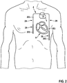
- an implantable defibrillation system has a defibrillation generator 1 which is to be implanted subcutaneously or under the chest muscle of a patient, for example, and to which an electrode line 2 (or several electrode lines, as will be described below) of an electrode line assembly 4 are connected.
- the electrode line 2 extends from the defibrillation generator 1 outside the heart H of the patient and is thus implanted in a non-transvenous manner, without direct access into the heart.
- the electrode line 2 thus runs outside the heart H of the patient.
- An electrode arrangement 20 arranged in the distal area on the electrode line 2 approaches the heart H from the outside, so that signals from the heart H can be recorded via the electrode arrangement 20 and electrical signals can also be delivered to the heart H for the purpose of stimulation.
- the electrode arrangement 20 of the electrode line 2 is shown in FIG Fig. 1 in the implanted state in particular approximates the right atrium RA and the right ventricle RV of the heart H.
- both atrial signals from the right atrium RA and ventricular signals from the right ventricle RV can be recorded via the electrode arrangement 20 and stimulation energy can also be emitted for the purpose of stimulation, in particular for the treatment of cardiac arrhythmias.
- a (single) non-transvenous electrode line 2 is connected to the defibrillation generator 1.
- two electrode lines 2A, 2B of a non-transvenous electrode line assembly 4 are connected to the defibrillation generator 1 in each case, the electrode lines 2A, 2B each being laid non-transvenously and thus outside the heart H of the patient.
- Each Electrode line 2A, 2B has an electrode arrangement 20 with electrode poles 202, 203.
- Fig. 3 illustrated embodiment, in comparison to the embodiment according to Fig. 2 , an additional electrode line 3 connected to the defibrillation generator 1, which is implanted transvenously and extends into the heart H, in particular - in the illustrated embodiment - into the right ventricle RV.
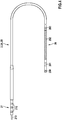
- Fig. 4 shows an embodiment of an electrode line 2, 2A, 2B, as it is in the embodiments according to Figs. 1 to 3 alone ( Fig. 1 ) or together with one or more other electrode lines ( Fig. 2 and 3 ) can be connected to a defibrillation generator 1.
- the electrode line 2, 2A, 2B has an electrode arrangement 20 which is formed by a plurality of electrode poles 200-203 and is arranged in the region of a distal end of the electrode line 2.
- the electrode line 2, 2A, 2B has a plug 21 on which connection poles 210 are arranged and which can be plugged into the defibrillation generator 1 in order to connect the electrode poles 200-203 to the defibrillation generator 1, received To supply signals to the defibrillation generator 1 and to lead stimulation energy to the electrode arrangement 20.
- the electrode arrangement 20 has a plurality of electrode poles 200-203.
- a connecting pole 210 can be assigned to each electrode pole 200-203, in which case the respective electrode pole 200-203 is connected to the assigned connecting pole 210 via a supply line.
- the number of connection poles 210 corresponds in this case to the number of electrode poles 200-203.
- individual electrode poles 200-203 can also be connected jointly to an assigned connection pole 210.
- the plug 21 has four connection poles 210 and is thus four-pole.
- the plug 21 can also, for example have a higher number of connection poles 210 and be designed, for example, six-pole or eight-pole.
- the electrode poles 200-203 are designed differently and fulfill different functions.
- a first electrode pole 202 referred to as a defibrillation electrode pole, is used to deliver stimulation energy and is arranged in a helical manner on the electrode line 2, 2A, 2B.
- the electrode line 2, 2A, 2B has a defibrillation electrode pole 202, to which stimulation energy from the defibrillation generator 1 can be supplied in order to deliver stimulation energy to the heart H for the purpose of defibrillation and to treat arrhythmias detected in this way.
- a second electrode pole 203 referred to as the ventricular sensing electrode pole, is used, for example, to detect ventricular signals, that is to say signals that have a ventricular origin and go back to a ventricular activity at the heart H.
- ventricular signals can be intrinsic, i.e. they can be traced back to an intrinsic activity of the heart.
- Such ventricular signals can, however, also be stimulated.
- Third electrode poles 200, 201 are in the FIG Fig. 4
- the illustrated embodiment is arranged in the region of the distal end of the electrode line 2.
- the sensing electrode poles 200, 201 are used, for example, to detect atrial signals and, when the electrode line 2, 2A, 2B is implanted, are arranged in the immediate spatial vicinity of the right atrium RA of the heart H, for example.
- the defibrillation electrode pole 202 is formed by a helix
- the ventricular sensing electrode pole 203 and the atrial sensing electrode pole 200, 201 are formed, for example, as ring electrodes which extend in a ring around the electrode line 2.
- the electrode poles 200-203 can be exposed to the outside and thus make electrical contact with the surrounding tissue of the patient.
- the atrial sensing electrode poles 200, 201 jointly form a dipole via which atrial signals can be received.
- the defibrillation generator 1 is, as exemplified in FIG Fig. 1-3 shown, designed so that one or more electrode lines 2, 2A, 2B can be connected to the defibrillation generator 1.
- the electrode lines 2, 2A, 2B can be of identical construction and, for example, as in FIG Fig. 4 be shown designed. However, it is also possible that differently configured electrode lines 2, 2A, 2B, for example electrode lines 2, 2A, 2B with a different number and arrangement of electrode poles, can be connected to the defibrillation generator 1.
- the defibrillation generator 1 has a housing 10 and a connection block 11 formed on the housing 10.
- the connection block 11 has connections 110, 112, 114, to which electrode lines 2, 2A, 2B, 3 can be connected, as exemplified in FIG Fig. 5 is shown.
- Each connection 110, 112, 114 here forms a plug connection into which an assigned plug 21, 31 of an assigned electrode line 2, 2A, 2B, 3 can be plugged in such that connection poles 210, 310 of the plug 21, 31 with assigned contact elements 111, 113, 115 of the connections 110, 112, 114 make electrical contact and thus establish an electrical connection between the electrode lines 2, 2A, 2B, 3 and the defibrillation generator 1.
- the defibrillation generator 1 has a control device 12, which is functionally connected to the connections 110, 112, 114, in particular the contact elements 111, 113, 115 of the connections 110, 112, 114, so that signals from the connections 110, 112, 114 are received and Signals to the connections 110, 112, 114 can be fed.
- the defibrillation generator 1 also has an energy store 13, in particular in the form of a battery.
- the defibrillation generator 1 can be implanted in a patient and should remain in the patient for a long period of time, for example several years. All components of the defibrillation generator 1 are encapsulated by the housing 10 and thus enclosed in a moisture-tight manner.
- the control device 12 can be configured to assume different operating states. Depending on the number and combination of electrode lines 2, 2A, 2B, 3 connected to the defibrillation generator 1, the control device 12 can be operated in different operating states in order to provide a defibrillation function for treating cardiac arrhythmias.
- the control device 12 has, for example, a first connection unit 121 which is assigned to a first connection 110, a second connection unit 122 which is assigned to a second connection 112, and a third connection unit 123 which is assigned to a third connection 114.
- the connection units 121-123 are each connected to a switching unit 124 via which the connection units 121-123 can be controlled in a variably configurable manner.
- control device 12 can be configured to receive and output signals only via the connection unit 121, so that a defibrillation function is provided via the electrode line 2 connected to the connection 110.
- connection 114 If an electrode line 3 implanted transvenously is also connected to the connection 114, signals are also received via the connection unit 123 and, if necessary, also emitted for intracardial stimulation.
- the switching unit 124 can be implemented by an electronic assembly. It is also conceivable that the switching unit 124 is implemented by control software and thus in terms of software (without a hardware switch).
- the switching unit 124 is functionally connected to a control unit 120 of the control device 12, which evaluates received signals for the purpose of diagnostics and therapy control.
- the control unit 120 is connected to a ventricular stimulation unit 125, an atrial stimulation unit 126 and a cardioversion / defibrillation unit 127, via which signals for ventricular and / or atrial stimulation and for defibrillation are generated and supplied to connected electrode lines 2, 2A, 2B, 3 can be.
- the control device 12 can be configured before implantation, during implantation or also after implantation.
- the configuration is carried out by programming, with the control device 12 being adapted to a connected combination of electrode lines 2, 2A, 2B, 3 through the configuration in order to be able to provide a defibrillation function accordingly via a connected combination of electrode lines 2, 2A, 2B, 3 .
- control device 12 can also be designed to automatically recognize which type and combination of electrode lines 2, 2A, 2B, 3 are connected to the defibrillation generator 1 in order to automatically carry out a configuration.
- defibrillation energy takes place via defibrillation electrode poles 202 from connected, non-transvenous implanted electrode lines 2, 2A, 2B.
- the connected electrode line 2 has a single defibrillation electrode pole 202 which, together with the housing 10 of the defibrillation generator 1, forms a dipole.
- the housing 10 thus represents a counter electrode for the defibrillation electrode pole 202 of the electrode line 2, so that stimulation energy can be injected into the heart H between the defibrillation electrode pole 202 and the housing 10.
- the in Fig. 2 and 3 have the non-transvenous implanted electrode lines 2A, 2B connected to the defibrillation generator 1 each have a defibrillation electrode pole. Stimulation energy can be delivered between the two defibrillation electrode poles 202 of the electrode lines 2A, 2B.
- the housing 10 of the defibrillation generator 1 can also be included as a counter electrode, for example by feeding stimulation energy between the defibrillation electrode pole 202 of one of the electrode lines 2A, 2B and the combination of the defibrillation electrode pole 202 of the other electrode line 2B, 2A and the housing 10 of the defibrillation generator 1 ( the defibrillation electrode pole 202 of the other electrode line 2B, 2A and the housing 10 of the defibrillation generator 1 serve together as a counter electrode).
- Atrial and / or ventricular signals can be picked up via sensing electrode poles 200, 203.
- Perception signals can be recorded between each of the perception electrode poles 200, 203 and the housing 10 of the defibrillation generator 1 as a counter electrode.
- signals can be recorded between the sensing electrodes 200, 203, which together form a dipole.
- An EKG can be derived from the perception signals, on the basis of which diagnostics and therapy control can be undertaken for any defibrillation that may be performed.
- each electrode line 2A, 2B has a sensing electrode pole 203.
- Sensing signals can correspondingly be sent between the sensing electrode poles 203 of the electrode lines 2A, 2B (which together form a dipole).
- perception signals can be recorded between the perception electrode pole 203 of each electrode line 2A, 2B and the housing 10 of the defibrillation generator 1 as a counter electrode.
- an EKG can be derived from the perception signals, which can be evaluated for diagnosis and therapy control.
- right ventricular anti-bradycardia stimulation and / or anti-tachycardia stimulation can take place via the additional electrode line 3 and the electrode arrangement 30 arranged distally thereon.
- atrial and / or ventricular signals can be recorded via the electrode arrangement 30 for the purpose of diagnostics and therapy control.
- An electrode line 3 can, for example, be added at a later point in time after an initial implantation of the defibrillation system, for example if slow ventricular tachycardias repeatedly occur in the patient or if the perception of signals is to be improved for the purpose of diagnosis and therapy control, for example because a perception of the -Transvenous electrode leads 2A, 2B is not sufficient.
- a transvenous coronary sinus electrode for example, can be connected to the defibrillation generator 1, which for this purpose can have an additional, fourth connection.
- Left ventricular stimulation and / or perception can take place via such a coronary sinus electrode.
- Electrode lines 2, 2A, 2B, 3 can be marked by a suitable marking, for example a text, a color marking or a radiopaque marking. Connections 110, 112, 114 of defibrillation generator 1 can also be marked.
- an electrode line assembly 4 consisting of the electrode lines 2, 2A, 2B is not implanted transvenously, the result is simple implantation of the Defibrillation system.
- the deflation generator 1 can be implanted subcutaneously or submuscularly, for example below the collarbone of a patient.
- Electrode leads 2, 2A, 2B can for example be implanted parasternally using a tunneling technique, for example, and thus extend outside the heart H of the patient.
- Electrode lines can be constructed differently than in the examples shown and can in particular have other combinations and arrangements of electrode poles.
- one or more electrode lines can be connected to a defibrillation generator, with at least some of the electrode lines not having to be implanted transvenously.
Priority Applications (6)
| Application Number | Priority Date | Filing Date | Title |
|---|---|---|---|
| EP19191170.0A EP3777968A1 (fr) | 2019-08-12 | 2019-08-12 | Système de défibrillation pouvant être implanté |
| PCT/EP2020/072360 WO2021028377A1 (fr) | 2019-08-12 | 2020-08-10 | Système de défibrillation implantable |
| EP20750686.6A EP4013491A1 (fr) | 2019-08-12 | 2020-08-10 | Système de défibrillation implantable |
| JP2021573320A JP2022543962A (ja) | 2019-08-12 | 2020-08-10 | 植込み型除細動システム |
| CN202080049530.9A CN114096308A (zh) | 2019-08-12 | 2020-08-10 | 可植入除颤系统 |
| US17/631,744 US20220273959A1 (en) | 2019-08-12 | 2020-08-10 | Implantable defibrillation system |
Applications Claiming Priority (1)
| Application Number | Priority Date | Filing Date | Title |
|---|---|---|---|
| EP19191170.0A EP3777968A1 (fr) | 2019-08-12 | 2019-08-12 | Système de défibrillation pouvant être implanté |
Publications (1)
| Publication Number | Publication Date |
|---|---|
| EP3777968A1 true EP3777968A1 (fr) | 2021-02-17 |
Family
ID=67614439
Family Applications (2)
| Application Number | Title | Priority Date | Filing Date |
|---|---|---|---|
| EP19191170.0A Withdrawn EP3777968A1 (fr) | 2019-08-12 | 2019-08-12 | Système de défibrillation pouvant être implanté |
| EP20750686.6A Pending EP4013491A1 (fr) | 2019-08-12 | 2020-08-10 | Système de défibrillation implantable |
Family Applications After (1)
| Application Number | Title | Priority Date | Filing Date |
|---|---|---|---|
| EP20750686.6A Pending EP4013491A1 (fr) | 2019-08-12 | 2020-08-10 | Système de défibrillation implantable |
Country Status (5)
| Country | Link |
|---|---|
| US (1) | US20220273959A1 (fr) |
| EP (2) | EP3777968A1 (fr) |
| JP (1) | JP2022543962A (fr) |
| CN (1) | CN114096308A (fr) |
| WO (1) | WO2021028377A1 (fr) |
Families Citing this family (1)
| Publication number | Priority date | Publication date | Assignee | Title |
|---|---|---|---|---|
| WO2023030891A1 (fr) * | 2021-09-02 | 2023-03-09 | Biotronik Se & Co. Kg | Défibrillateur à synchronisation automatique implantable |
Citations (4)
| Publication number | Priority date | Publication date | Assignee | Title |
|---|---|---|---|---|
| US20040215240A1 (en) * | 2003-04-11 | 2004-10-28 | Lovett Eric G. | Reconfigurable subcutaneous cardiac device |
| US20040230273A1 (en) * | 2003-04-11 | 2004-11-18 | Cates Adam W. | Subcutaneous electrode and lead with temporary pharmacological agents |
| US20160045754A1 (en) * | 2014-08-12 | 2016-02-18 | Cyberonics, Inc. | Vagus nerve stimulation and subcutaneous defibrillation system |
| WO2017196477A1 (fr) * | 2016-05-12 | 2017-11-16 | University Of Florida Research Foundation, Inc. | Défibrillation sous-cutanée |
-
2019
- 2019-08-12 EP EP19191170.0A patent/EP3777968A1/fr not_active Withdrawn
-
2020
- 2020-08-10 JP JP2021573320A patent/JP2022543962A/ja active Pending
- 2020-08-10 CN CN202080049530.9A patent/CN114096308A/zh active Pending
- 2020-08-10 US US17/631,744 patent/US20220273959A1/en active Pending
- 2020-08-10 EP EP20750686.6A patent/EP4013491A1/fr active Pending
- 2020-08-10 WO PCT/EP2020/072360 patent/WO2021028377A1/fr unknown
Patent Citations (4)
| Publication number | Priority date | Publication date | Assignee | Title |
|---|---|---|---|---|
| US20040215240A1 (en) * | 2003-04-11 | 2004-10-28 | Lovett Eric G. | Reconfigurable subcutaneous cardiac device |
| US20040230273A1 (en) * | 2003-04-11 | 2004-11-18 | Cates Adam W. | Subcutaneous electrode and lead with temporary pharmacological agents |
| US20160045754A1 (en) * | 2014-08-12 | 2016-02-18 | Cyberonics, Inc. | Vagus nerve stimulation and subcutaneous defibrillation system |
| WO2017196477A1 (fr) * | 2016-05-12 | 2017-11-16 | University Of Florida Research Foundation, Inc. | Défibrillation sous-cutanée |
Also Published As
| Publication number | Publication date |
|---|---|
| US20220273959A1 (en) | 2022-09-01 |
| JP2022543962A (ja) | 2022-10-17 |
| WO2021028377A1 (fr) | 2021-02-18 |
| CN114096308A (zh) | 2022-02-25 |
| EP4013491A1 (fr) | 2022-06-22 |
Similar Documents
| Publication | Publication Date | Title |
|---|---|---|
| EP2060299B1 (fr) | Stimulateur cardiaque bi-ventriculaire | |
| DE69933010T2 (de) | Vorrichtung zur überwachung und behandlung von arrythmien des herzens | |
| DE60204286T2 (de) | Implantierbare vorrichtung | |
| DE69831567T2 (de) | Einrichtung zur behandlung von herzarrhythien | |
| DE60108417T2 (de) | Herzstimulationsvorrichtung | |
| DE69919983T2 (de) | System zum einleiten von herzkammerflimmern unter verwendung von nahfeldwellenabtastung | |
| DE3818136A1 (de) | Defibrillationssystem und kardioversionsverfahren | |
| EP1774988B1 (fr) | Dispositif implantable pour la détermination des vecteurs cardiaques | |
| EP0559933A1 (fr) | Configuration d'électrodes pour un défibrillateur/cardioverteur implantable | |
| EP2135640A1 (fr) | Dispositif d'électrothérapie destiné au traitement de défaillances du rythme tachycarde d'un cýur | |
| EP3328482B1 (fr) | Systeme d'electrode a courant continu implantable | |
| DE60031640T2 (de) | Vorrichtung zur Erkennung einer natürlichen elektrischen Kohärenz im Herz und zur Verabreichung einer darauf basierenden Therapie | |
| EP3025759A1 (fr) | Appareil implantable actif adapté pour une utilisation avec irm | |
| DE102019121719A1 (de) | Implantierbares Defibrillationssystem | |
| EP2111892B1 (fr) | Stimulateur cardiaque contre la tachychardie | |
| EP3777968A1 (fr) | Système de défibrillation pouvant être implanté | |
| EP2181648B1 (fr) | Stimulateur cardiaque à une chambre | |
| EP2140910B1 (fr) | Stimulateur cardiaque destiné au traitement des rythmes tachycardiques | |
| EP0793979B1 (fr) | Appareil pour la détermination de la fréquence cardiaque | |
| EP2111894B1 (fr) | Stimulateur cardiaque doté d'un contrôle de la réussite de la stimulation | |
| DE19930267B4 (de) | Defibrillator | |
| EP2826522B1 (fr) | Stimulateur cardiaque | |
| EP2111893A1 (fr) | Stimulateur cardiaque ventriculaire | |
| EP2826523B1 (fr) | Appareil thérapeutique cardiaque implantable | |
| EP3025757A1 (fr) | Appareil actif implantable pour mrt et capteur mrt |
Legal Events
| Date | Code | Title | Description |
|---|---|---|---|
| PUAI | Public reference made under article 153(3) epc to a published international application that has entered the european phase |
Free format text: ORIGINAL CODE: 0009012 |
|
| STAA | Information on the status of an ep patent application or granted ep patent |
Free format text: STATUS: THE APPLICATION HAS BEEN PUBLISHED |
|
| AK | Designated contracting states |
Kind code of ref document: A1 Designated state(s): AL AT BE BG CH CY CZ DE DK EE ES FI FR GB GR HR HU IE IS IT LI LT LU LV MC MK MT NL NO PL PT RO RS SE SI SK SM TR |
|
| AX | Request for extension of the european patent |
Extension state: BA ME |
|
| STAA | Information on the status of an ep patent application or granted ep patent |
Free format text: STATUS: THE APPLICATION IS DEEMED TO BE WITHDRAWN |
|
| 18D | Application deemed to be withdrawn |
Effective date: 20210818 |