EP3777968A1 - Implantable defibrillation system - Google Patents
Implantable defibrillation system Download PDFInfo
- Publication number
- EP3777968A1 EP3777968A1 EP19191170.0A EP19191170A EP3777968A1 EP 3777968 A1 EP3777968 A1 EP 3777968A1 EP 19191170 A EP19191170 A EP 19191170A EP 3777968 A1 EP3777968 A1 EP 3777968A1
- Authority
- EP
- European Patent Office
- Prior art keywords
- electrode
- defibrillation
- electrode line
- generator
- pole
- Prior art date
- Legal status (The legal status is an assumption and is not a legal conclusion. Google has not performed a legal analysis and makes no representation as to the accuracy of the status listed.)
- Withdrawn
Links
Images


Classifications
-
- A—HUMAN NECESSITIES
- A61—MEDICAL OR VETERINARY SCIENCE; HYGIENE
- A61N—ELECTROTHERAPY; MAGNETOTHERAPY; RADIATION THERAPY; ULTRASOUND THERAPY
- A61N1/00—Electrotherapy; Circuits therefor
- A61N1/18—Applying electric currents by contact electrodes
- A61N1/32—Applying electric currents by contact electrodes alternating or intermittent currents
- A61N1/38—Applying electric currents by contact electrodes alternating or intermittent currents for producing shock effects
- A61N1/39—Heart defibrillators
- A61N1/3956—Implantable devices for applying electric shocks to the heart, e.g. for cardioversion
-
- A—HUMAN NECESSITIES
- A61—MEDICAL OR VETERINARY SCIENCE; HYGIENE
- A61N—ELECTROTHERAPY; MAGNETOTHERAPY; RADIATION THERAPY; ULTRASOUND THERAPY
- A61N1/00—Electrotherapy; Circuits therefor
- A61N1/02—Details
- A61N1/04—Electrodes
- A61N1/05—Electrodes for implantation or insertion into the body, e.g. heart electrode
- A61N1/0504—Subcutaneous electrodes
-
- A—HUMAN NECESSITIES
- A61—MEDICAL OR VETERINARY SCIENCE; HYGIENE
- A61N—ELECTROTHERAPY; MAGNETOTHERAPY; RADIATION THERAPY; ULTRASOUND THERAPY
- A61N1/00—Electrotherapy; Circuits therefor
- A61N1/02—Details
- A61N1/04—Electrodes
- A61N1/05—Electrodes for implantation or insertion into the body, e.g. heart electrode
- A61N1/056—Transvascular endocardial electrode systems
- A61N1/0563—Transvascular endocardial electrode systems specially adapted for defibrillation or cardioversion
-
- A—HUMAN NECESSITIES
- A61—MEDICAL OR VETERINARY SCIENCE; HYGIENE
- A61N—ELECTROTHERAPY; MAGNETOTHERAPY; RADIATION THERAPY; ULTRASOUND THERAPY
- A61N1/00—Electrotherapy; Circuits therefor
- A61N1/18—Applying electric currents by contact electrodes
- A61N1/32—Applying electric currents by contact electrodes alternating or intermittent currents
- A61N1/36—Applying electric currents by contact electrodes alternating or intermittent currents for stimulation
- A61N1/372—Arrangements in connection with the implantation of stimulators
- A61N1/375—Constructional arrangements, e.g. casings
- A61N1/3752—Details of casing-lead connections
- A61N1/3754—Feedthroughs
-
- A—HUMAN NECESSITIES
- A61—MEDICAL OR VETERINARY SCIENCE; HYGIENE
- A61N—ELECTROTHERAPY; MAGNETOTHERAPY; RADIATION THERAPY; ULTRASOUND THERAPY
- A61N1/00—Electrotherapy; Circuits therefor
- A61N1/18—Applying electric currents by contact electrodes
- A61N1/32—Applying electric currents by contact electrodes alternating or intermittent currents
- A61N1/38—Applying electric currents by contact electrodes alternating or intermittent currents for producing shock effects
- A61N1/39—Heart defibrillators
- A61N1/3968—Constructional arrangements, e.g. casings
Definitions
- the present invention relates to a defibrillation generator according to the preamble of claim 1, an implantable defibrillation system and a method for configuring an implantable defibrillation system.
- Such a defibrillation generator comprises a housing, a connection block for connecting an electrode lead assembly which is to be implanted non-transvenously in a patient, and a control device for controlling the operation of the defibrillation generator.
- Such a defibrillation system also known as an implantable cardioverter defibrillator (short: ICD) is used to detect and treat potentially life-threatening cardiac arrhythmias (ventricular tachycardia, bradycardia, ventricular fibrillation).
- ICD implantable cardioverter defibrillator
- Such a defibrillation system is implanted in a patient in such a way that one or more electrode lines extend from a defibrillation generator to the human heart, on the one hand to receive signals there for the purpose of recognizing cardiac arrhythmias and, on the other hand, to emit stimulation energy, in particular to generate an electrical shock Defibrillation). Both the electrode leads and the defibrillation generator are permanently implanted and remain in the patient for a longer period of time, usually several years.
- the defibrillation generator is implanted subcutaneously and electrode leads are laid transvenously directly into the heart via a venous access.
- electrode leads are laid transvenously directly into the heart via a venous access.
- the object of the present invention is to provide a defibrillation generator, an implantable defibrillation system and a method for configuring an implantable defibrillation system, which allow simple implantation with variable usability and optionally retrofitting with additional electrode lines.
- connection block has two connections, to each of which an electrode line of the electrode line assembly having at least one defibrillation electrode pole can be connected
- the control device for adopting a first operating state if an electrode line is connected to only one of the two connections, or a second operating state if on the two connections each have an electrode line connected, can be configured to provide a defibrillation function via the electrode line connected to one of the connections in the first operating state and a defibrillation function via the electrode lines connected to the two connections in the second operating state.
- the defibrillation generator has a connection block which has two (or more) connections.
- the defibrillation generator can optionally be equipped with one or more electrode lines of an electrode line assembly to be implanted non-transvenously in a patient, so that the defibrillation generator has only one connected electrode line or with two connected electrode lines or possibly also with more than two connected electrode lines can be operated.
- the lead leads of the lead lead assembly are non-transvenous to implant in a patient.
- This means that the electrode lines of the electrode line assembly are to be laid outside the patient's heart, for example subcutaneously or submuscularly.
- the electrode lines of the electrode line assembly to be implanted non-transvenously thus do not extend into the heart of the patient via a venous access, but rather run outside the heart.
- Electrodes lines of the electrode line assembly that is not to be transvenously implanted, there are further electrode lines that may need to be implanted transvenously in the heart.
- additional electrode lines can, as will be explained below, serve, for example, for intracardiac perception and / or stimulation.
- the defibrillation generator should be able to be operated with only one connected electrode line of the electrode line assembly or with more than one connected electrode line of the electrode line assembly.
- the defibrillation generator is designed to provide a defibrillation function so that electrical stimulation energy, for example with a maximum energy of 45 J or more, can be delivered via a connected electrode line assembly in order to cause defibrillation if a cardiac arrhythmia is detected.
- the control device of the defibrillation generator can be configured to assume a first operating state or a second operating state.
- the first operating state is designed to provide a defibrillation function when an electrode line is connected to only one of the two connections of the connection block of the defibrillation generator.
- the second operating state is designed to provide a defibrillation function To be made available if electrode lines are connected to (at least) two connections of the connection block.
- the control device can, for example, have a switching unit which, for example, is implemented by an electronic assembly or implemented by control software of the control device.
- the switching unit signals are only fed to one connection in the first operating state and, if necessary, received by one connection.
- signals are sent to both connections and possibly received by both connections for the purpose of evaluation.
- the fact that the electrode lines of the electrode line assembly are not implanted transvenously results in a simple implantation technique, for example using a tunneling rod.
- An implantation process can thus be made considerably easier, possibly avoiding the general anesthesia required for the implantation and reducing the risk of an operation.
- the simple implantation also enables simple retrofitting by connecting additional electrode lines to an already implanted defibrillation generator, for which purpose the defibrillation generator can be reconfigured in order to operate the defibrillation generator with additional electrode lines.
- connection block has a third connection for connecting an electrode line to be implanted transvenously intracardially.
- intracardiac stimulation and / or perception of intracardial signals can take place via such an electrode line to be implanted transvenously intracardially.
- Such an additional third electrode line in contrast to the electrode lines of the electrode line assembly that is not to be implanted transvenously, is transvenous into the heart to be laid inside so that the defibrillation generator can also be operated with a transvenous electrode line.
- connection block can have a fourth connection for connecting a coronary sinus electrode line to be implanted transvenously.
- a coronary sinus electrode line can be laid into the heart for left ventricular stimulation and / or perception.
- control device can be configurable in order to operate the defibrillation generator with or without an additional, transvenous electrode line connected to the third connection and / or the fourth connection.
- defibrillation can be carried out using the defibrillation electrode poles of the electrode lines that form a dipole. If only one electrode line is connected to one of the two connections of the connection block, the electrode line can optionally have two defibrillation electrode poles which form a dipole for emitting stimulation energy for the purpose of defibrillation.
- the housing of the defibrillation generator can also serve as a counter electrode, so that a dipole between a defibrillation electrode pole of an electrode line and the Housing of the defibrillation generator is formed.
- the defibrillation generator can be configured to generate defibrillation energy via a predetermined dipole (between the defibrillation electrode poles of the Electrode lines or between a defibrillation electrode pole and the housing of the defibrillation generator), whereby the configuration can be carried out once during commissioning or repeatedly during operation, for example depending on an effective excitation.
- An implantable defibrillation system comprises a defibrillation generator of the type described above and an electrode lead assembly which is to be implanted non-transvenously in a patient.
- the electrode line assembly comprises in particular a first electrode line for connection to a first connection of the connection block of the defibrillation generator and a second electrode line for connection to a second connection of the connection block of the defibrillation generator. Both the first electrode line and the second electrode line have at least one defibrillation electrode pole, so that the electrode lines can be used jointly or separately from one another to deliver stimulation energy for the purpose of defibrillation.
- the electrode lines can optionally be connected to the defibrillation generator, the defibrillation generator being configured differently depending on which electrode lines are connected to the defibrillation generator. In the context of the configuration, it can also be determined via which dipole (between different defibrillation electrode poles or between a defibrillation electrode pole and the housing of the defibrillation generator), if necessary, stimulation energy for the purpose of defibrillation is to be delivered during operation.
- the first electrode line and / or the second electrode line have at least one sensing electrode pole for detecting ventricular and / or atrial signals. Sensing can thus also take place via electrode lines of the electrode line assembly that is not to be implanted transvenously in order to detect cardiac arrhythmias and to control a stimulation.
- Such perception electrode poles can be designed, for example, as ring electrodes and thus extend in a ring shape around the assigned electrode line.
- a defibrillation electrode pole of an electrode line can be designed as a helix and thus extends helically around the associated electrode line. Due to the helical configuration, the surface of the defibrillation electrode pole is enlarged so that electrical shock energy can be efficiently emitted and introduced into the heart, with sufficient flexibility on the electrode line for flexible, possibly curved installation in the patient.
- an atrial sensing electrode pole of an electrode line of the electrode line assembly is arranged at a distal end of the respective electrode line.
- the distal end here corresponds to the end of the electrode line that faces away from a proximal end that can be connected to the defibrillation generator.
- the atrial sensing electrode pole is thus placed distally from the defibrillation generator, wherein the atrial sensing electrode pole can be arranged directly at the distal end and in this case, for example, covers the tip of the electrode line.
- the electrode line with the atrial sensing electrode pole arranged thereon is approximated, for example, to the right atrium of the patient's heart, so that atrial signals can be picked up via the atrial sensing electrode pole and fed to the defibrillation generator.
- a sensing electrode pole serving to receive atrial signals can additionally or alternatively also be arranged proximally offset to the distal end of the electrode line, the sensing electrode pole however being arranged distally from the proximal end of the electrode line.
- At least one of the electrode lines of the electrode line assembly has two sensing electrode poles that implement a dipole for detecting atrial signals.
- the two sensing electrode poles can be arranged for example in the area of the distal end of the electrode line. It is also possible, however, for the sensing electrode poles to be arranged on the electrode line at a greater distance from one another. Signals can be picked up between the two sensing electrode poles which originate from atrial activity of the heart and thus enable atrial sensing signals to be detected.
- an atrial sensing electrode pole is arranged on a first side of a defibrillation electrode pole and a ventricular sensing electrode pole is arranged on a second side of the defibrillation electrode pole of an electrode lead. Atrial signals and ventricular signals are thus perceived and via different perception electrode poles at different, axially offset locations on the electrode line.
- the defibrillation system has a third electrode line for connection to a third connection of the connection block of the defibrillation generator.
- a third electrode lead can be implanted transvenously in the heart and has an electrode arrangement with one or more electrode poles, for example in order to receive signals intracardially in the right ventricle or in the right atrium or to effect a stimulation.
- the control device of the defibrillation generator can be configured in such a way that signals can be received via the electrode line for the purpose of perception and / or signals can be output to the third electrode line for the purpose of stimulation.
- each electrode line of the electrode line assembly has a plug which can be plugged into an associated plug connection of the defibrillation generator in order to connect the electrode line to the defibrillation generator.
- all electrode poles of the electrode line can be functionally connected to the defibrillation generator via a single connector.
- the plug can, for example, have connection poles which, when connected to the plug connection of the defibrillation generator, make electrical contact with associated contact elements of the plug connection, so that electrical leads of the electrode line are connected to the defibrillation generator.
- the plug can, for example, be two-pole, four-pole, six-pole, eight-pole or even with more poles.
- the control device of the defibrillation generator can have a first receiving channel for processing ventricular signals received via the electrode line assembly and a second receiving channel for processing atrial signals received via the electrode line assembly.
- a separate receiving channel is thus provided for receiving and processing atrial signals, in which the atrial signals are processed separately.
- the second receiving channel for processing the atrial signals can have a different gain and a different filter characteristic than the first receiving channel for processing the ventricular signals. In this way, atrial signals can be received with higher sensitivity, for example with a sensitivity of less than 1 mV, preferably less than 0.1 mV, more preferably less than 0.05 mV.
- Atrial signals can be filtered in a special way, in particular to suppress other, possibly interfering signals, for example ventricular signals, for example using a cyclical time window in which interfering signals are suppressed (so-called "blanking window"). Atrial signals can also be processed in order to analyze signal characteristics, for example a maximum (positive and / or negative) amplitude, a peak-to-peak value, a pulse width or a (positive and / or negative) mean value.
- signal characteristics for example a maximum (positive and / or negative) amplitude, a peak-to-peak value, a pulse width or a (positive and / or negative) mean value.
- a method for configuring an implantable defibrillation system comprising: providing a defibrillation generator which has a housing, a connection block for connecting an electrode lead assembly and a control device for controlling the operation of the defibrillation generator; Providing an electrode line assembly comprising at least one electrode line, wherein the electrode line assembly is non-transvenous to be implanted in a patient; either connecting an electrode line of the electrode line assembly having at least one defibrillation electrode pole to one of two connections of the connection block or connecting two electrode lines of the electrode line assembly each having at least one defibrillation electrode pole to the two connections of the connection block; and configuring a switching unit of the control device to assume a first operating state when an electrode line is connected to only one of the two connections, or a second operating state when an electrode line is connected to each of the two connections, the control device having a defibrillation function in the first operating state the electrode line connected to one of the connections and, in the second operating state
- the control device can be configured before the implantation of the defibrillation generator and the electrode lead assembly, during the implantation of the defibrillation generator and the electrode lead assembly, or after the implantation of the defibrillation generator and the electrode lead assembly.
- the defibrillation generator can be implanted subcutaneously or submuscularly in a patient.
- One or more electrode leads of the electrode lead assemblies can be implanted subcutaneously or submuscularly using a tunneling technique, for example.
- a tunneling technique for example, a blunt tunneling rod, onto which a so-called introducer is pushed, is moved through the patient's tissue around an implantation path for laying an electrode lead to pretend. The tunneling rod is then withdrawn while the introducer remains in its assumed position and thus forms a tunnel through which the electrode line can be introduced for the purpose of implantation.
- the electrode line can have a distal fixing mechanism which can be activated when the electrode line has reached its intended position.
- the introducer can be withdrawn on the electrode to remove the introducer. This can be done by fanning out the introducer (so-called "peeling").
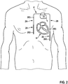
- an implantable defibrillation system has a defibrillation generator 1 which is to be implanted subcutaneously or under the chest muscle of a patient, for example, and to which an electrode line 2 (or several electrode lines, as will be described below) of an electrode line assembly 4 are connected.
- the electrode line 2 extends from the defibrillation generator 1 outside the heart H of the patient and is thus implanted in a non-transvenous manner, without direct access into the heart.
- the electrode line 2 thus runs outside the heart H of the patient.
- An electrode arrangement 20 arranged in the distal area on the electrode line 2 approaches the heart H from the outside, so that signals from the heart H can be recorded via the electrode arrangement 20 and electrical signals can also be delivered to the heart H for the purpose of stimulation.
- the electrode arrangement 20 of the electrode line 2 is shown in FIG Fig. 1 in the implanted state in particular approximates the right atrium RA and the right ventricle RV of the heart H.
- both atrial signals from the right atrium RA and ventricular signals from the right ventricle RV can be recorded via the electrode arrangement 20 and stimulation energy can also be emitted for the purpose of stimulation, in particular for the treatment of cardiac arrhythmias.
- a (single) non-transvenous electrode line 2 is connected to the defibrillation generator 1.
- two electrode lines 2A, 2B of a non-transvenous electrode line assembly 4 are connected to the defibrillation generator 1 in each case, the electrode lines 2A, 2B each being laid non-transvenously and thus outside the heart H of the patient.
- Each Electrode line 2A, 2B has an electrode arrangement 20 with electrode poles 202, 203.
- Fig. 3 illustrated embodiment, in comparison to the embodiment according to Fig. 2 , an additional electrode line 3 connected to the defibrillation generator 1, which is implanted transvenously and extends into the heart H, in particular - in the illustrated embodiment - into the right ventricle RV.
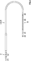
- Fig. 4 shows an embodiment of an electrode line 2, 2A, 2B, as it is in the embodiments according to Figs. 1 to 3 alone ( Fig. 1 ) or together with one or more other electrode lines ( Fig. 2 and 3 ) can be connected to a defibrillation generator 1.
- the electrode line 2, 2A, 2B has an electrode arrangement 20 which is formed by a plurality of electrode poles 200-203 and is arranged in the region of a distal end of the electrode line 2.
- the electrode line 2, 2A, 2B has a plug 21 on which connection poles 210 are arranged and which can be plugged into the defibrillation generator 1 in order to connect the electrode poles 200-203 to the defibrillation generator 1, received To supply signals to the defibrillation generator 1 and to lead stimulation energy to the electrode arrangement 20.
- the electrode arrangement 20 has a plurality of electrode poles 200-203.
- a connecting pole 210 can be assigned to each electrode pole 200-203, in which case the respective electrode pole 200-203 is connected to the assigned connecting pole 210 via a supply line.
- the number of connection poles 210 corresponds in this case to the number of electrode poles 200-203.
- individual electrode poles 200-203 can also be connected jointly to an assigned connection pole 210.
- the plug 21 has four connection poles 210 and is thus four-pole.
- the plug 21 can also, for example have a higher number of connection poles 210 and be designed, for example, six-pole or eight-pole.
- the electrode poles 200-203 are designed differently and fulfill different functions.
- a first electrode pole 202 referred to as a defibrillation electrode pole, is used to deliver stimulation energy and is arranged in a helical manner on the electrode line 2, 2A, 2B.
- the electrode line 2, 2A, 2B has a defibrillation electrode pole 202, to which stimulation energy from the defibrillation generator 1 can be supplied in order to deliver stimulation energy to the heart H for the purpose of defibrillation and to treat arrhythmias detected in this way.
- a second electrode pole 203 referred to as the ventricular sensing electrode pole, is used, for example, to detect ventricular signals, that is to say signals that have a ventricular origin and go back to a ventricular activity at the heart H.
- ventricular signals can be intrinsic, i.e. they can be traced back to an intrinsic activity of the heart.
- Such ventricular signals can, however, also be stimulated.
- Third electrode poles 200, 201 are in the FIG Fig. 4
- the illustrated embodiment is arranged in the region of the distal end of the electrode line 2.
- the sensing electrode poles 200, 201 are used, for example, to detect atrial signals and, when the electrode line 2, 2A, 2B is implanted, are arranged in the immediate spatial vicinity of the right atrium RA of the heart H, for example.
- the defibrillation electrode pole 202 is formed by a helix
- the ventricular sensing electrode pole 203 and the atrial sensing electrode pole 200, 201 are formed, for example, as ring electrodes which extend in a ring around the electrode line 2.
- the electrode poles 200-203 can be exposed to the outside and thus make electrical contact with the surrounding tissue of the patient.
- the atrial sensing electrode poles 200, 201 jointly form a dipole via which atrial signals can be received.
- the defibrillation generator 1 is, as exemplified in FIG Fig. 1-3 shown, designed so that one or more electrode lines 2, 2A, 2B can be connected to the defibrillation generator 1.
- the electrode lines 2, 2A, 2B can be of identical construction and, for example, as in FIG Fig. 4 be shown designed. However, it is also possible that differently configured electrode lines 2, 2A, 2B, for example electrode lines 2, 2A, 2B with a different number and arrangement of electrode poles, can be connected to the defibrillation generator 1.
- the defibrillation generator 1 has a housing 10 and a connection block 11 formed on the housing 10.
- the connection block 11 has connections 110, 112, 114, to which electrode lines 2, 2A, 2B, 3 can be connected, as exemplified in FIG Fig. 5 is shown.
- Each connection 110, 112, 114 here forms a plug connection into which an assigned plug 21, 31 of an assigned electrode line 2, 2A, 2B, 3 can be plugged in such that connection poles 210, 310 of the plug 21, 31 with assigned contact elements 111, 113, 115 of the connections 110, 112, 114 make electrical contact and thus establish an electrical connection between the electrode lines 2, 2A, 2B, 3 and the defibrillation generator 1.
- the defibrillation generator 1 has a control device 12, which is functionally connected to the connections 110, 112, 114, in particular the contact elements 111, 113, 115 of the connections 110, 112, 114, so that signals from the connections 110, 112, 114 are received and Signals to the connections 110, 112, 114 can be fed.
- the defibrillation generator 1 also has an energy store 13, in particular in the form of a battery.
- the defibrillation generator 1 can be implanted in a patient and should remain in the patient for a long period of time, for example several years. All components of the defibrillation generator 1 are encapsulated by the housing 10 and thus enclosed in a moisture-tight manner.
- the control device 12 can be configured to assume different operating states. Depending on the number and combination of electrode lines 2, 2A, 2B, 3 connected to the defibrillation generator 1, the control device 12 can be operated in different operating states in order to provide a defibrillation function for treating cardiac arrhythmias.
- the control device 12 has, for example, a first connection unit 121 which is assigned to a first connection 110, a second connection unit 122 which is assigned to a second connection 112, and a third connection unit 123 which is assigned to a third connection 114.
- the connection units 121-123 are each connected to a switching unit 124 via which the connection units 121-123 can be controlled in a variably configurable manner.
- control device 12 can be configured to receive and output signals only via the connection unit 121, so that a defibrillation function is provided via the electrode line 2 connected to the connection 110.
- connection 114 If an electrode line 3 implanted transvenously is also connected to the connection 114, signals are also received via the connection unit 123 and, if necessary, also emitted for intracardial stimulation.
- the switching unit 124 can be implemented by an electronic assembly. It is also conceivable that the switching unit 124 is implemented by control software and thus in terms of software (without a hardware switch).
- the switching unit 124 is functionally connected to a control unit 120 of the control device 12, which evaluates received signals for the purpose of diagnostics and therapy control.
- the control unit 120 is connected to a ventricular stimulation unit 125, an atrial stimulation unit 126 and a cardioversion / defibrillation unit 127, via which signals for ventricular and / or atrial stimulation and for defibrillation are generated and supplied to connected electrode lines 2, 2A, 2B, 3 can be.
- the control device 12 can be configured before implantation, during implantation or also after implantation.
- the configuration is carried out by programming, with the control device 12 being adapted to a connected combination of electrode lines 2, 2A, 2B, 3 through the configuration in order to be able to provide a defibrillation function accordingly via a connected combination of electrode lines 2, 2A, 2B, 3 .
- control device 12 can also be designed to automatically recognize which type and combination of electrode lines 2, 2A, 2B, 3 are connected to the defibrillation generator 1 in order to automatically carry out a configuration.
- defibrillation energy takes place via defibrillation electrode poles 202 from connected, non-transvenous implanted electrode lines 2, 2A, 2B.
- the connected electrode line 2 has a single defibrillation electrode pole 202 which, together with the housing 10 of the defibrillation generator 1, forms a dipole.
- the housing 10 thus represents a counter electrode for the defibrillation electrode pole 202 of the electrode line 2, so that stimulation energy can be injected into the heart H between the defibrillation electrode pole 202 and the housing 10.
- the in Fig. 2 and 3 have the non-transvenous implanted electrode lines 2A, 2B connected to the defibrillation generator 1 each have a defibrillation electrode pole. Stimulation energy can be delivered between the two defibrillation electrode poles 202 of the electrode lines 2A, 2B.
- the housing 10 of the defibrillation generator 1 can also be included as a counter electrode, for example by feeding stimulation energy between the defibrillation electrode pole 202 of one of the electrode lines 2A, 2B and the combination of the defibrillation electrode pole 202 of the other electrode line 2B, 2A and the housing 10 of the defibrillation generator 1 ( the defibrillation electrode pole 202 of the other electrode line 2B, 2A and the housing 10 of the defibrillation generator 1 serve together as a counter electrode).
- Atrial and / or ventricular signals can be picked up via sensing electrode poles 200, 203.
- Perception signals can be recorded between each of the perception electrode poles 200, 203 and the housing 10 of the defibrillation generator 1 as a counter electrode.
- signals can be recorded between the sensing electrodes 200, 203, which together form a dipole.
- An EKG can be derived from the perception signals, on the basis of which diagnostics and therapy control can be undertaken for any defibrillation that may be performed.
- each electrode line 2A, 2B has a sensing electrode pole 203.
- Sensing signals can correspondingly be sent between the sensing electrode poles 203 of the electrode lines 2A, 2B (which together form a dipole).
- perception signals can be recorded between the perception electrode pole 203 of each electrode line 2A, 2B and the housing 10 of the defibrillation generator 1 as a counter electrode.
- an EKG can be derived from the perception signals, which can be evaluated for diagnosis and therapy control.
- right ventricular anti-bradycardia stimulation and / or anti-tachycardia stimulation can take place via the additional electrode line 3 and the electrode arrangement 30 arranged distally thereon.
- atrial and / or ventricular signals can be recorded via the electrode arrangement 30 for the purpose of diagnostics and therapy control.
- An electrode line 3 can, for example, be added at a later point in time after an initial implantation of the defibrillation system, for example if slow ventricular tachycardias repeatedly occur in the patient or if the perception of signals is to be improved for the purpose of diagnosis and therapy control, for example because a perception of the -Transvenous electrode leads 2A, 2B is not sufficient.
- a transvenous coronary sinus electrode for example, can be connected to the defibrillation generator 1, which for this purpose can have an additional, fourth connection.
- Left ventricular stimulation and / or perception can take place via such a coronary sinus electrode.
- Electrode lines 2, 2A, 2B, 3 can be marked by a suitable marking, for example a text, a color marking or a radiopaque marking. Connections 110, 112, 114 of defibrillation generator 1 can also be marked.
- an electrode line assembly 4 consisting of the electrode lines 2, 2A, 2B is not implanted transvenously, the result is simple implantation of the Defibrillation system.
- the deflation generator 1 can be implanted subcutaneously or submuscularly, for example below the collarbone of a patient.
- Electrode leads 2, 2A, 2B can for example be implanted parasternally using a tunneling technique, for example, and thus extend outside the heart H of the patient.
- Electrode lines can be constructed differently than in the examples shown and can in particular have other combinations and arrangements of electrode poles.
- one or more electrode lines can be connected to a defibrillation generator, with at least some of the electrode lines not having to be implanted transvenously.
Abstract
Ein Defibrillationsgenerator (1) für ein implantierbares Defibrillationssystem umfasst ein Gehäuse (10), einen Anschlussblock (11) zum Anschließen einer Elektrodenleitungsbaugruppe (4), die nicht-transvenös in einem Patienten zu implantieren ist, und eine Steuereinrichtung (12) zum Steuern des Betriebs des Defibrillationsgenerators (1). Der Anschlussblock (11) weist zwei Anschlüsse (110, 112) auf, an die jeweils eine zumindest einen Defibrillationselektrodenpol (202) aufweisende Elektrodenleitung (2, 2A, 2B) der Elektrodenleitungsbaugruppe (4) anschließbar ist, wobei die Steuereinrichtung (12) zum Einnehmen eines ersten Betriebszustands, wenn nur an einen der zwei Anschlüsse (110, 112) eine Elektrodenleitung (2, 2A, 2B) angeschlossen ist, oder eines zweiten Betriebszustands, wenn an die zwei Anschlüsse (110, 112) jeweils eine Elektrodenleitung (2, 2A, 2B) angeschlossen ist, konfigurierbar ist.A defibrillation generator (1) for an implantable defibrillation system comprises a housing (10), a connection block (11) for connecting an electrode lead assembly (4) which is to be implanted non-transvenously in a patient, and a control device (12) for controlling the operation the defibrillation generator (1). The connection block (11) has two connections (110, 112) to each of which an electrode line (2, 2A, 2B) of the electrode line assembly (4), which has at least one defibrillation electrode pole (202), can be connected, the control device (12) for taking a first operating state when an electrode line (2, 2A, 2B) is connected to only one of the two connections (110, 112), or a second operating state when an electrode line (2, 2A , 2B) is connected, is configurable.
Description
Die vorliegende Erfindung betrifft einen Defibrillationsgenerator nach dem Oberbegriff des Anspruchs 1, ein implantierbares Defibrillationssystem und ein Verfahren zur Konfiguration eines implantierbaren Defibrillationssystems.The present invention relates to a defibrillation generator according to the preamble of claim 1, an implantable defibrillation system and a method for configuring an implantable defibrillation system.
Ein solcher Defibrillationsgenerator umfasst ein Gehäuse, einen Anschlussblock zum Anschließen einer Elektrodenleitungsbaugruppe, die nicht-transvenös in einem Patienten zu implantieren ist, und eine Steuereinrichtung zum Steuern des Betriebs des Defibrillationsgenerators.Such a defibrillation generator comprises a housing, a connection block for connecting an electrode lead assembly which is to be implanted non-transvenously in a patient, and a control device for controlling the operation of the defibrillation generator.
Ein solches Defibrillationssystem, auch bezeichnet als implantierbarer Cardioverter-Defibrillator (kurz: ICD), dient zur Erkennung und Behandlung von möglicherweise lebensbedrohlichen Herzrhythmusstörungen (Kammertachykardie, Bradykardie, Kammerflimmern). Ein solches Defibrillationssystem wird in einem Patienten implantiert derart, dass eine oder mehrere Elektrodenleitungen ausgehend von einem Defibrillationsgenerator sich hin zum menschlichen Herzen erstrecken, um dort zum einen Signale zum Zwecke der Erkennung von Herzrhythmusstörungen aufzunehmen und zum anderen Stimulationsenergie abzugeben, insbesondere um einen elektrischen Schock (Defibrillation) zu bewirken. Sowohl die Elektrodenleitungen als auch der Defibrillationsgenerator werden hierbei fest implantiert und verbleiben über einen längeren Zeitraum, üblicherweise mehrere Jahre, im Patienten.Such a defibrillation system, also known as an implantable cardioverter defibrillator (short: ICD), is used to detect and treat potentially life-threatening cardiac arrhythmias (ventricular tachycardia, bradycardia, ventricular fibrillation). Such a defibrillation system is implanted in a patient in such a way that one or more electrode lines extend from a defibrillation generator to the human heart, on the one hand to receive signals there for the purpose of recognizing cardiac arrhythmias and, on the other hand, to emit stimulation energy, in particular to generate an electrical shock Defibrillation). Both the electrode leads and the defibrillation generator are permanently implanted and remain in the patient for a longer period of time, usually several years.
Bei üblichen Defibrillationssystemen wird der Defibrillationsgenerator subkutan implantiert, und Elektrodenleitungen werden über einen Venenzugang transvenös direkt in das Herz hinein verlegt. Obwohl sich solche Defibrillationssysteme in der Praxis bewährt haben, kann wünschenswert sein, andere Defibrillationssysteme zur Verfügung zu stellen, die einfacher zu implantieren, gegebenenfalls durch Hinzufügen weiterer Elektrodenleitungen nachrüstbar und auch einfacher wieder zu entfernen sind, insbesondere unter Vermeidung eines direkten, transvenösen Zugangs in das Herz hinein.In conventional defibrillation systems, the defibrillation generator is implanted subcutaneously and electrode leads are laid transvenously directly into the heart via a venous access. Although such defibrillation systems have proven themselves in practice, it may be desirable to provide other defibrillation systems that are easier to implant, can be retrofitted if necessary by adding additional electrode lines and are also easier to remove, especially avoiding direct, transvenous access to the Heart into it.
Aufgabe der vorliegenden Erfindung ist es, einen Defibrillationsgenerator, ein implantierbares Defibrillationssystem und ein Verfahren zur Konfiguration eines implantierbaren Defibrillationssystems zur Verfügung zu stellen, die ein einfaches Implantieren bei variabler Verwendbarkeit und gegebenenfalls Nachrüstbarkeit mit zusätzlichen Elektrodenleitungen ermöglichen.The object of the present invention is to provide a defibrillation generator, an implantable defibrillation system and a method for configuring an implantable defibrillation system, which allow simple implantation with variable usability and optionally retrofitting with additional electrode lines.
Diese Aufgabe wird durch einen Gegenstand mit den Merkmalen des Anspruchs 1 gelöst.This object is achieved by an object having the features of claim 1.
Demnach weist der Anschlussblock zwei Anschlüsse auf, an die jeweils eine zumindest einen Defibrillationselektrodenpol aufweisende Elektrodenleitung der Elektrodenleitungsbaugruppe anschließbar ist, wobei die Steuereinrichtung zum Einnehmen eines ersten Betriebszustands, wenn nur an einen der zwei Anschlüsse eine Elektrodenleitung angeschlossen ist, oder eines zweiten Betriebszustands, wenn an die zwei Anschlüsse jeweils eine Elektrodenleitung angeschlossen ist, konfigurierbar ist, um in dem ersten Betriebszustand eine Defibrillationsfunktion über die an den einen der Anschlüsse angeschlossene Elektrodenleitung und in dem zweiten Betriebszustand eine Defibrillationsfunktion über die an die zwei Anschlüsse angeschlossenen Elektrodenleitungen bereitzustellen.Accordingly, the connection block has two connections, to each of which an electrode line of the electrode line assembly having at least one defibrillation electrode pole can be connected, the control device for adopting a first operating state if an electrode line is connected to only one of the two connections, or a second operating state if on the two connections each have an electrode line connected, can be configured to provide a defibrillation function via the electrode line connected to one of the connections in the first operating state and a defibrillation function via the electrode lines connected to the two connections in the second operating state.
Der Defibrillationsgenerator weist einen Anschlussblock auf, der zwei (oder mehr) Anschlüsse aufweist. Der Defibrillationsgenerator kann hierbei wahlweise mit einer oder mit mehreren Elektrodenleitungen einer nicht-transvenös in einem Patienten zu implantierenden Elektrodenleitungsbaugruppe bestückt werden, sodass der Defibrillationsgenerator mit lediglich einer angeschlossenen Elektrodenleitung oder mit zwei angeschlossenen Elektrodenleitungen oder gegebenenfalls auch mit mehr als zwei angeschlossenen Elektrodenleitungen betrieben werden kann.The defibrillation generator has a connection block which has two (or more) connections. The defibrillation generator can optionally be equipped with one or more electrode lines of an electrode line assembly to be implanted non-transvenously in a patient, so that the defibrillation generator has only one connected electrode line or with two connected electrode lines or possibly also with more than two connected electrode lines can be operated.
Die Elektrodenleitungen der Elektrodenleitungsbaugruppe sind nicht-transvenös in einem Patienten zu implantieren. Hierunter ist zu verstehen, dass die Elektrodenleitungen der Elektrodenleitungsbaugruppe außerhalb des Herzens des Patienten zu verlegen sind, beispielsweise subkutan oder submuskulär. Die Elektrodenleitungen der nicht-transvenös zu implantierenden Elektrodenleitungsbaugruppe erstrecken sich somit nicht über einen venösen Zugang in das Herz des Patienten hinein, sondern verlaufen außerhalb des Herzens.The lead leads of the lead lead assembly are non-transvenous to implant in a patient. This means that the electrode lines of the electrode line assembly are to be laid outside the patient's heart, for example subcutaneously or submuscularly. The electrode lines of the electrode line assembly to be implanted non-transvenously thus do not extend into the heart of the patient via a venous access, but rather run outside the heart.
Nicht ausgeschlossen ist, dass über die Elektrodenleitungen der nicht-transvenös zu implantierenden Elektrodenleitungsbaugruppe hinaus weitere Elektrodenleitungen vorhanden sind, die gegebenenfalls transvenös im Herzen zu implantieren sind. Solche zusätzlichen Elektrodenleitungen können, wie nachfolgend noch erläutert werden soll, beispielsweise für eine intrakardiale Wahrnehmung und/oder Stimulation dienen.It is not ruled out that, in addition to the electrode lines of the electrode line assembly that is not to be transvenously implanted, there are further electrode lines that may need to be implanted transvenously in the heart. Such additional electrode lines can, as will be explained below, serve, for example, for intracardiac perception and / or stimulation.
Der Defibrillationsgenerator soll mit lediglich einer angeschlossenen Elektrodenleitung der Elektrodenleitungsbaugruppe oder mit mehr als einer angeschlossenen Elektrodenleitung der Elektrodenleitungsbaugruppe betrieben werden können. Jeweils ist der Defibrillationsgenerator hierbei zum Bereitstellen einer Defibrillationsfunktion ausgestaltet, sodass über eine angeschlossene Elektrodenleitungsbaugruppe elektrische Stimulationsenergie, beispielsweise mit einer maximalen Energie von 45 J oder darüber, abgegeben werden kann, um bei Detektion einer Herzrhythmusstörung eine Defibrillation zu bewirken.The defibrillation generator should be able to be operated with only one connected electrode line of the electrode line assembly or with more than one connected electrode line of the electrode line assembly. In each case, the defibrillation generator is designed to provide a defibrillation function so that electrical stimulation energy, for example with a maximum energy of 45 J or more, can be delivered via a connected electrode line assembly in order to cause defibrillation if a cardiac arrhythmia is detected.
Die Steuereinrichtung des Defibrillationsgenerators ist konfigurierbar, um einen ersten Betriebszustand oder einen zweiten Betriebszustand einzunehmen. Der erste Betriebszustand ist hierbei dazu ausgestaltet, eine Defibrillationsfunktion zur Verfügung zu stellen, wenn nur an einen der zwei Anschlüsse des Anschlussblocks des Defibrillationsgenerators eine Elektrodenleitung angeschlossen ist. Der zweite Betriebszustand ist demgegenüber dazu ausgestaltet, eine Defibrillationsfunktion zur Verfügung zu stellen, wenn an (zumindest) zwei Anschlüsse des Anschlussblocks Elektrodenleitungen angeschlossen sind.The control device of the defibrillation generator can be configured to assume a first operating state or a second operating state. The first operating state is designed to provide a defibrillation function when an electrode line is connected to only one of the two connections of the connection block of the defibrillation generator. In contrast, the second operating state is designed to provide a defibrillation function To be made available if electrode lines are connected to (at least) two connections of the connection block.
Abhängig davon, ob der Defibrillationsgenerator mit einer Elektrodenleitung oder mit zwei Elektrodenleitungen bestückt ist, wird eine Defibrillationsfunktion somit über die eine angeschlossene Elektrodenleitung oder unter Verwendung von zwei angeschlossenen Elektrodenleitungen zur Verfügung gestellt. Zum Umschalten zwischen den unterschiedlichen Betriebszuständen kann die Steuereinrichtung beispielsweise eine Schalteinheit aufweisen, die beispielsweise durch eine elektronische Baugruppe verwirklicht oder durch eine Steuerungssoftware der Steuereinrichtung umgesetzt ist. Mittels der Schalteinheit werden in dem ersten Betriebszustand Signale lediglich einem Anschluss zugeleitet und gegebenenfalls von dem einen Anschluss empfangen. In dem zweiten Betriebszustand hingegen werden Signale an beide Anschlüsse geleitet und gegebenenfalls von beiden Anschlüssen zum Zwecke der Auswertung empfangen.Depending on whether the defibrillation generator is equipped with one electrode line or with two electrode lines, a defibrillation function is thus made available via one connected electrode line or using two connected electrode lines. To switch between the different operating states, the control device can, for example, have a switching unit which, for example, is implemented by an electronic assembly or implemented by control software of the control device. By means of the switching unit, signals are only fed to one connection in the first operating state and, if necessary, received by one connection. In the second operating state, on the other hand, signals are sent to both connections and possibly received by both connections for the purpose of evaluation.
Dadurch, dass die Elektrodenleitungen der Elektrodenleitungsbaugruppe nicht-transvenös implantiert werden, ergibt sich eine einfache Implantationstechnik, beispielsweise unter Verwendung eines Tunnelierstabs. Ein Implantationsvorgang kann somit erheblich erleichtert sein, gegebenenfalls unter Vermeidung einer für die Implantation erforderlichen Vollnarkose und bei Reduzierung eines Operationsrisikos. Die einfache Implantation ermöglicht auch das einfache Nachrüsten durch Anschließen weiterer Elektrodenleitungen an einen bereits implantierten Defibrillationsgenerator, wobei zu diesem Zweck der Defibrillationsgenerator umkonfiguriert werden kann, um den Defibrillationsgenerator mit weiteren Elektrodenleitungen zu betreiben.The fact that the electrode lines of the electrode line assembly are not implanted transvenously results in a simple implantation technique, for example using a tunneling rod. An implantation process can thus be made considerably easier, possibly avoiding the general anesthesia required for the implantation and reducing the risk of an operation. The simple implantation also enables simple retrofitting by connecting additional electrode lines to an already implanted defibrillation generator, for which purpose the defibrillation generator can be reconfigured in order to operate the defibrillation generator with additional electrode lines.
In einer Ausgestaltung weist der Anschlussblock einen dritten Anschluss zum Anschließen einer transvenös intrakardial zu implantierenden Elektrodenleitung auf. Über solch eine transvenös intrakardial zu implantierende Elektrodenleitung kann beispielsweise eine intrakardiale Stimulation und/oder Wahrnehmung von intrakardialen Signalen, beispielsweise atrialen Signalen und/oder ventrikulären Signalen, erfolgen. Eine solche zusätzliche dritte Elektrodenleitung ist, im Unterschied zu den Elektrodenleitungen der nicht-transvenös zu implantierenden Elektrodenleitungsbaugruppe, transvenös in das Herz hinein zu verlegen, sodass der Defibrillationsgenerator zusätzlich auch mit einer transvenösen Elektrodenleitung betrieben werden kann.In one embodiment, the connection block has a third connection for connecting an electrode line to be implanted transvenously intracardially. For example, intracardiac stimulation and / or perception of intracardial signals, for example atrial signals and / or ventricular signals, can take place via such an electrode line to be implanted transvenously intracardially. Such an additional third electrode line, in contrast to the electrode lines of the electrode line assembly that is not to be implanted transvenously, is transvenous into the heart to be laid inside so that the defibrillation generator can also be operated with a transvenous electrode line.
Zusätzlich oder alternativ kann der Anschlussblock einen vierten Anschluss zum Anschließen einer transvenös zu implantierenden Coronarsinus-Elektrodenleitung aufweisen. Eine solche Coronarsinus-Elektrodenleitung kann zur linksventrikulären Stimulation und/oder Wahrnehmung in das Herz hinein verlegt sein.Additionally or alternatively, the connection block can have a fourth connection for connecting a coronary sinus electrode line to be implanted transvenously. Such a coronary sinus electrode line can be laid into the heart for left ventricular stimulation and / or perception.
Jeweils kann die Steuereinrichtung konfigurierbar sein, um den Defibrillationsgenerator mit oder ohne eine an den dritten Anschluss und/oder den vierten Anschluss angeschlossene, zusätzliche, transvenöse Elektrodenleitung zu betreiben.In each case, the control device can be configurable in order to operate the defibrillation generator with or without an additional, transvenous electrode line connected to the third connection and / or the fourth connection.
Sind zwei Elektrodenleitungen der Elektrodenleitungsbaugruppe, die jeweils einen Defibrillationselektrodenpol zum Abgeben von Stimulationspulsen zum Zwecke der Defibrillation aufweisen, an den Defibrillationsgenerator angeschlossen, kann eine Defibrillation unter Verwendung der einen Dipol ausbildenden Defibrillationselektrodenpole der Elektrodenleitungen vorgenommen werden. Ist lediglich eine Elektrodenleitung an einen der zwei Anschlüsse des Anschlussblocks angeschlossen, so kann die Elektrodenleitung gegebenenfalls zwei Defibrillationselektrodenpole aufweisen, die einen Dipol zum Abgeben von Stimulationsenergie zum Zwecke der Defibrillation ausbilden.If two electrode lines of the electrode line assembly, each having a defibrillation electrode pole for delivering stimulation pulses for the purpose of defibrillation, are connected to the defibrillation generator, defibrillation can be carried out using the defibrillation electrode poles of the electrode lines that form a dipole. If only one electrode line is connected to one of the two connections of the connection block, the electrode line can optionally have two defibrillation electrode poles which form a dipole for emitting stimulation energy for the purpose of defibrillation.
Sowohl bei zwei an den Defibrillationsgenerator angeschlossenen, jeweils einen Defibrillationselektrodenpol aufweisenden Elektrodenleitungen als auch bei einer einzigen an den Defibrillationsgenerator angeschlossenen, einen oder mehrere Defibrillationselektrodenpole aufweisenden Elektrodenleitung kann aber auch das Gehäuse des Defibrillationsgenerators als Gegenelektrode dienen, sodass ein Dipol zwischen einem Defibrillationselektrodenpol einer Elektrodenleitung und dem Gehäuse des Defibrillationsgenerators gebildet ist.Both with two electrode lines connected to the defibrillation generator and each having a defibrillation electrode pole and with a single electrode line connected to the defibrillation generator and having one or more defibrillation electrode poles, the housing of the defibrillation generator can also serve as a counter electrode, so that a dipole between a defibrillation electrode pole of an electrode line and the Housing of the defibrillation generator is formed.
Der Defibrillationsgenerator kann hierbei konfiguriert werden, um Defibrillationsenergie über einen vorbestimmten Dipol (zwischen Defibrillationselektrodenpolen der Elektrodenleitungen oder zwischen einem Defibrillationselektrodenpol und dem Gehäuse des Defibrillationsgenerators) abzugeben, wobei die Konfiguration einmalig bei Inbetriebnahme oder wiederholt im Betrieb, zum Beispiel abhängig von einer effektiven Anregung, erfolgen kann.The defibrillation generator can be configured to generate defibrillation energy via a predetermined dipole (between the defibrillation electrode poles of the Electrode lines or between a defibrillation electrode pole and the housing of the defibrillation generator), whereby the configuration can be carried out once during commissioning or repeatedly during operation, for example depending on an effective excitation.
Ein implantierbares Defibrillationssystem umfasst einen Defibrillationsgenerator der vorangehend beschriebenen Art und eine Elektrodenleitungsbaugruppe, die nicht-transvenös in einem Patienten zu implantieren ist. Die Elektrodenleitungsbaugruppe umfasst hierbei insbesondere eine erste Elektrodenleitung zum Anschließen an einen ersten Anschluss des Anschlussblocks des Defibrillationsgenerators und eine zweite Elektrodenleitung zum Anschließen an einen zweiten Anschluss des Anschlussblocks des Defibrillationsgenerators. Sowohl die erste Elektrodenleitung als auch die zweite Elektrodenleitung weisen zumindest einen Defibrillationselektrodenpol auf, sodass die Elektrodenleitungen gemeinsam oder gesondert voneinander zur Abgabe von Stimulationsenergie zum Zwecke der Defibrillation verwendet werden können.An implantable defibrillation system comprises a defibrillation generator of the type described above and an electrode lead assembly which is to be implanted non-transvenously in a patient. The electrode line assembly comprises in particular a first electrode line for connection to a first connection of the connection block of the defibrillation generator and a second electrode line for connection to a second connection of the connection block of the defibrillation generator. Both the first electrode line and the second electrode line have at least one defibrillation electrode pole, so that the electrode lines can be used jointly or separately from one another to deliver stimulation energy for the purpose of defibrillation.
Die Elektrodenleitungen können hierbei wahlweise an den Defibrillationsgenerator angeschlossen werden, wobei der Defibrillationsgenerator abhängig davon, welche Elektrodenleitungen an den Defibrillationsgenerator angeschlossen sind, unterschiedlich konfiguriert werden kann. Im Rahmen der Konfiguration kann auch festgelegt werden, über welchen Dipol (zwischen unterschiedlichen Defibrillationselektrodenpolen oder zwischen einem Defibrillationselektrodenpol und dem Gehäuse des Defibrillationsgenerators) im Betrieb gegebenenfalls Stimulationsenergie zum Zwecke der Defibrillation abgegeben werden soll.The electrode lines can optionally be connected to the defibrillation generator, the defibrillation generator being configured differently depending on which electrode lines are connected to the defibrillation generator. In the context of the configuration, it can also be determined via which dipole (between different defibrillation electrode poles or between a defibrillation electrode pole and the housing of the defibrillation generator), if necessary, stimulation energy for the purpose of defibrillation is to be delivered during operation.
In einer Ausgestaltung weisen die erste Elektrodenleitung und/oder die zweite Elektrodenleitung zumindest einen Wahrnehmungselektrodenpol zum Detektieren von ventrikulären und/oder atrialen Signalen auf. Über Elektrodenleitungen der nicht-transvenös zu implantierenden Elektrodenleitungsbaugruppe kann somit auch eine Wahrnehmung erfolgen, um Herzrhythmusstörungen zu detektieren und eine Stimulation zu steuern.In one embodiment, the first electrode line and / or the second electrode line have at least one sensing electrode pole for detecting ventricular and / or atrial signals. Sensing can thus also take place via electrode lines of the electrode line assembly that is not to be implanted transvenously in order to detect cardiac arrhythmias and to control a stimulation.
Solche Wahrnehmungselektrodenpole können zum Beispiel als Ringelektrode ausgebildet sein und erstrecken sich somit ringförmig um die zugeordnete Elektrodenleitung herum.Such perception electrode poles can be designed, for example, as ring electrodes and thus extend in a ring shape around the assigned electrode line.
Ein Defibrillationselektrodenpol einer Elektrodenleitung kann demgegenüber als Wendel ausgebildet sein und erstreckt sich somit wendelförmig um die zugeordnete Elektrodenleitung herum. Aufgrund der wendelförmigen Ausgestaltung ist die Oberfläche des Defibrillationselektrodenpols vergrößert, sodass elektrische Schockenergie in effizienter Weise abgegeben und in das Herz eingeleitet werden kann, bei dennoch hinreichender Flexibilität an der Elektrodenleitung zur flexiblen, gegebenenfalls gekrümmten Verlegung im Patienten.In contrast, a defibrillation electrode pole of an electrode line can be designed as a helix and thus extends helically around the associated electrode line. Due to the helical configuration, the surface of the defibrillation electrode pole is enlarged so that electrical shock energy can be efficiently emitted and introduced into the heart, with sufficient flexibility on the electrode line for flexible, possibly curved installation in the patient.
In einer Ausgestaltung ist ein atrialer Wahrnehmungselektrodenpol einer Elektrodenleitung der Elektrodenleitungsbaugruppe an einem distalen Ende der jeweiligen Elektrodenleitung angeordnet. Das distale Ende entspricht hierbei dem Ende der Elektrodenleitung, das einem an den Defibrillationsgenerator anschließbaren, proximalen Ende abgewandt ist. Der atriale Wahrnehmungselektrodenpol ist bei dieser Ausgestaltung somit distal von dem Defibrillationsgenerator platziert, wobei der atriale Wahrnehmungselektrodenpol unmittelbar am distalen Ende angeordnet sein kann und in diesem Fall beispielsweise die Spitze der Elektrodenleitung überdeckt. In implantiertem Zustand ist die Elektrodenleitung mit dem daran angeordneten atrialen Wahrnehmungselektrodenpol beispielsweise dem rechten Atrium des Herzens des Patienten angenähert, sodass über den atrialen Wahrnehmungselektrodenpol atriale Signale aufgenommen und dem Defibrillationsgenerator zugeleitet werden können.In one configuration, an atrial sensing electrode pole of an electrode line of the electrode line assembly is arranged at a distal end of the respective electrode line. The distal end here corresponds to the end of the electrode line that faces away from a proximal end that can be connected to the defibrillation generator. In this embodiment, the atrial sensing electrode pole is thus placed distally from the defibrillation generator, wherein the atrial sensing electrode pole can be arranged directly at the distal end and in this case, for example, covers the tip of the electrode line. In the implanted state, the electrode line with the atrial sensing electrode pole arranged thereon is approximated, for example, to the right atrium of the patient's heart, so that atrial signals can be picked up via the atrial sensing electrode pole and fed to the defibrillation generator.
Ein zur Aufnahme atrialer Signale dienender Wahrnehmungselektrodenpol kann zusätzlich oder alternativ aber auch proximal versetzt zum distalen Ende der Elektrodenleitung angeordnet sein, wobei der Wahrnehmungselektrodenpol aber distal vom proximalen Ende der Elektrodenleitung angeordnet ist.A sensing electrode pole serving to receive atrial signals can additionally or alternatively also be arranged proximally offset to the distal end of the electrode line, the sensing electrode pole however being arranged distally from the proximal end of the electrode line.
In einer Ausgestaltung weist zumindest eine der Elektrodenleitungen der Elektrodenleitungsbaugruppe zwei Wahrnehmungselektrodenpole auf, die einen Dipol zum Detektieren atrialer Signale verwirklichen. Die zwei Wahrnehmungselektrodenpole können beispielsweise im Bereich des distalen Endes der Elektrodenleitung angeordnet sein. Möglich ist aber auch, dass die Wahrnehmungselektrodenpole weiter beabstandet voneinander an der Elektrodenleitung angeordnet sind. Zwischen den zwei Wahrnehmungselektrodenpolen können Signale aufgenommen werden, die ihren Ursprung in atrialer Aktivität des Herzens haben und somit ein Detektieren von atrialen Wahrnehmungssignalen ermöglichen.In one embodiment, at least one of the electrode lines of the electrode line assembly has two sensing electrode poles that implement a dipole for detecting atrial signals. The two sensing electrode poles can be arranged for example in the area of the distal end of the electrode line. It is also possible, however, for the sensing electrode poles to be arranged on the electrode line at a greater distance from one another. Signals can be picked up between the two sensing electrode poles which originate from atrial activity of the heart and thus enable atrial sensing signals to be detected.
In einer Ausgestaltung sind ein atrialer Wahrnehmungselektrodenpol an einer ersten Seite eines Defibrillationselektrodenpols und ein ventrikulärer Wahrnehmungselektrodenpol an einer zweiten Seite des Defibrillationselektrodenpols einer Elektrodenleitung angeordnet. Eine Wahrnehmung atrialer Signale und ventrikulärer Signale erfolgt somit und über unterschiedliche Wahrnehmungselektrodenpole an unterschiedlichen, axial zueinander versetzten Orten der Elektrodenleitung.In one embodiment, an atrial sensing electrode pole is arranged on a first side of a defibrillation electrode pole and a ventricular sensing electrode pole is arranged on a second side of the defibrillation electrode pole of an electrode lead. Atrial signals and ventricular signals are thus perceived and via different perception electrode poles at different, axially offset locations on the electrode line.
In einer Ausgestaltung weist das Defibrillationssystem eine dritte Elektrodenleitung zum Anschließen an einen dritten Anschluss des Anschlussblocks des Defibrillationsgenerators auf. Eine solche dritte Elektrodenleitung kann transvenös im Herzen zu implantieren sein und weist eine Elektrodenanordnung mit einem oder mehreren Elektrodenpolen auf, beispielsweise um intrakardial im rechten Ventrikel oder im rechten Atrium Signale aufzunehmen oder eine Stimulation zu bewirken. Die Steuereinrichtung des Defibrillationsgenerators kann hierbei derart konfigurierbar sein, dass Signale über die Elektrodenleitung zum Zwecke der Wahrnehmung empfangen und/oder Signale zum Zwecke der Stimulation an die dritte Elektrodenleitung abgegeben werden können.In one embodiment, the defibrillation system has a third electrode line for connection to a third connection of the connection block of the defibrillation generator. Such a third electrode lead can be implanted transvenously in the heart and has an electrode arrangement with one or more electrode poles, for example in order to receive signals intracardially in the right ventricle or in the right atrium or to effect a stimulation. The control device of the defibrillation generator can be configured in such a way that signals can be received via the electrode line for the purpose of perception and / or signals can be output to the third electrode line for the purpose of stimulation.
In einer Ausgestaltung weist jede Elektrodenleitung der Elektrodenleitungsbaugruppe einen Stecker auf, der in einen zugeordneten Steckanschluss des Defibrillationsgenerators eingesteckt werden kann, um die Elektrodenleitung an den Defibrillationsgenerator anzuschließen. Über einen einzigen Stecker können hierbei beispielsweise sämtliche Elektrodenpole der Elektrodenleitung funktional mit dem Defibrillationsgenerator verbunden werden. Der Stecker kann beispielsweise Anschlusspole aufweisen, die bei steckendem Verbinden mit dem Steckanschluss des Defibrillationsgenerators mit zugeordneten Kontaktelementen des Steckanschlusses elektrisch kontaktieren, sodass elektrische Zuleitungen der Elektrodenleitung an den Defibrillationsgenerator angeschlossen werden.In one embodiment, each electrode line of the electrode line assembly has a plug which can be plugged into an associated plug connection of the defibrillation generator in order to connect the electrode line to the defibrillation generator. For example, all electrode poles of the electrode line can be functionally connected to the defibrillation generator via a single connector. The plug can, for example, have connection poles which, when connected to the plug connection of the defibrillation generator, make electrical contact with associated contact elements of the plug connection, so that electrical leads of the electrode line are connected to the defibrillation generator.
Der Stecker kann beispielsweise zweipolig, vierpolig, sechspolig, achtpolig oder auch noch höherpolig sein.The plug can, for example, be two-pole, four-pole, six-pole, eight-pole or even with more poles.
Die Steuereinrichtung des Defibrillationsgenerators kann, in einer Ausgestaltung, einen ersten Empfangskanal zum Verarbeiten von über die Elektrodenleitungsbaugruppe empfangenen, ventrikulären Signalen und einen zweiten Empfangskanal zum Verarbeiten von über die Elektrodenleitungsbaugruppe empfangenen, atrialen Signalen ausweisen. Für das Aufnehmen und Verarbeiten atrialer Signale wird somit ein eigener Empfangskanal vorgesehen, in dem die atrialen Signale gesondert verarbeitet werden. Insbesondere kann der zweite Empfangskanal zum Verarbeiten der atrialen Signale eine andere Verstärkung und eine andere Filtercharakteristik als der erste Empfangskanal zum Verarbeiten der ventrikulären Signale aufweisen. Auf diese Weise können atriale Signale mit höherer Empfindlichkeit empfangen werden, beispielsweise mit einer Empfindlichkeit kleiner 1 mV, vorzugsweise kleiner 0,1 mV, weiter vorzugsweise kleiner 0,05 mV.In one embodiment, the control device of the defibrillation generator can have a first receiving channel for processing ventricular signals received via the electrode line assembly and a second receiving channel for processing atrial signals received via the electrode line assembly. A separate receiving channel is thus provided for receiving and processing atrial signals, in which the atrial signals are processed separately. In particular, the second receiving channel for processing the atrial signals can have a different gain and a different filter characteristic than the first receiving channel for processing the ventricular signals. In this way, atrial signals can be received with higher sensitivity, for example with a sensitivity of less than 1 mV, preferably less than 0.1 mV, more preferably less than 0.05 mV.
Atriale Signale können hierbei in besonderer Weise gefiltert werden, insbesondere zum Unterdrücken anderer, gegebenenfalls störender Signale, beispielsweise ventrikulärer Signale, zum Beispiel unter Verwendung eines zyklischen Zeitfensters, in dem störende Signale unterdrückt werden (sogenanntes "Blanking Window"). Atriale Signale können hierbei zudem verarbeitet werden, um Signalcharakteristiken zu analysieren, beispielsweise eine maximale (positive und/oder negative) Amplitude, einen Spitzen-zu-Spitzenwert, eine Pulsbreite oder einen (positiven und/oder negativen) Mittelwert.Atrial signals can be filtered in a special way, in particular to suppress other, possibly interfering signals, for example ventricular signals, for example using a cyclical time window in which interfering signals are suppressed (so-called "blanking window"). Atrial signals can also be processed in order to analyze signal characteristics, for example a maximum (positive and / or negative) amplitude, a peak-to-peak value, a pulse width or a (positive and / or negative) mean value.
Die Aufgabe wird auch gelöst durch ein Verfahren zur Konfiguration eines implantierbaren Defibrillationssystems, aufweisend: Bereitstellen eines Defibrillationsgenerators, der ein Gehäuse, einen Anschlussblock zum Anschließen einer Elektrodenleitungsbaugruppe und eine Steuereinrichtung zum Steuern des Betriebs des Defibrillationsgenerators aufweist; Bereitstellen einer zumindest eine Elektrodenleitung umfassenden Elektrodenleitungsbaugruppe, wobei die Elektrodenleitungsbaugruppe nicht-transvenös in einem Patienten zu implantieren ist; entweder Anschließen von einer zumindest einen Defibrillationselektrodenpol aufweisenden Elektrodenleitung der Elektrodenleitungsbaugruppe an einen von zwei Anschlüssen des Anschlussblocks oder Anschließen von zwei jeweils zumindest einen Defibrillationselektrodenpol aufweisenden Elektrodenleitungen der Elektrodenleitungsbaugruppe an die zwei Anschlüsse des Anschlussblocks; und Konfigurieren einer Schalteinheit der Steuereinrichtung zum Einnehmen eines ersten Betriebszustands, wenn nur an einen der zwei Anschlüsse eine Elektrodenleitung angeschlossen ist, oder eines zweiten Betriebszustands, wenn an die zwei Anschlüsse jeweils eine Elektrodenleitung angeschlossen ist, wobei die Steuereinrichtung in dem ersten Betriebszustand eine Defibrillationsfunktion über die an den einen der Anschlüsse angeschlossene Elektrodenleitung und in dem zweiten Betriebszustand eine Defibrillationsfunktion über die an die zwei Anschlüsse angeschlossenen Elektrodenleitungen bereitstellt.The object is also achieved by a method for configuring an implantable defibrillation system, comprising: providing a defibrillation generator which has a housing, a connection block for connecting an electrode lead assembly and a control device for controlling the operation of the defibrillation generator; Providing an electrode line assembly comprising at least one electrode line, wherein the electrode line assembly is non-transvenous to be implanted in a patient; either connecting an electrode line of the electrode line assembly having at least one defibrillation electrode pole to one of two connections of the connection block or connecting two electrode lines of the electrode line assembly each having at least one defibrillation electrode pole to the two connections of the connection block; and configuring a switching unit of the control device to assume a first operating state when an electrode line is connected to only one of the two connections, or a second operating state when an electrode line is connected to each of the two connections, the control device having a defibrillation function in the first operating state the electrode line connected to one of the connections and, in the second operating state, provides a defibrillation function via the electrode lines connected to the two connections.
Bezüglich des Verfahrens gelten die gleichen Vorteile und vorteilhaften Ausgestaltungen wie vorangehend für den Defibrillationsgenerator und das Defibrillationssystem beschrieben, sodass diesbezüglich vollumfänglich auf das vorangehend Ausgeführte verwiesen werden soll.With regard to the method, the same advantages and advantageous refinements apply as described above for the defibrillation generator and the defibrillation system, so that in this regard reference should be made in full to what has been stated above.
Die Konfiguration der Steuereinrichtung kann vor der Implantation des Defibrillationsgenerators und der Elektrodenleitungsbaugruppe, während der Implantation des Defibrillationsgenerators und der Elektrodenleitungsbaugruppe oder nach der Implantation des Defibrillationsgenerators und der Elektrodenleitungsbaugruppe erfolgen.The control device can be configured before the implantation of the defibrillation generator and the electrode lead assembly, during the implantation of the defibrillation generator and the electrode lead assembly, or after the implantation of the defibrillation generator and the electrode lead assembly.
Der Defibrillationsgenerator kann hierbei zum Beispiel subkutan oder submuskulär in einem Patienten implantiert werden.The defibrillation generator can be implanted subcutaneously or submuscularly in a patient.
Eine oder mehrere Elektrodenleitungen der Elektrodenleitungsbaugruppen können beispielsweise unter Verwendung einer Tunneliertechnik subkutan oder submuskulär implantiert werden. Im Rahmen einer solchen Tunneliertechnik wird ein stumpfer Tunnelierstab, auf den ein sogenannter Introducer aufgeschoben ist, durch Gewebe des Patienten bewegt, um einen Implantierpfad zum Verlegen einer Elektrodenleitung vorzugeben. Der Tunnelierstab wird anschließend zurückgezogen, während der Introducer in seiner eingenommenen Position verbleibt und somit einen Tunnel ausbildet, durch den die Elektrodenleitung zum Zwecke der Implantation eingebracht werden kann.One or more electrode leads of the electrode lead assemblies can be implanted subcutaneously or submuscularly using a tunneling technique, for example. In the context of such a tunneling technique, a blunt tunneling rod, onto which a so-called introducer is pushed, is moved through the patient's tissue around an implantation path for laying an electrode lead to pretend. The tunneling rod is then withdrawn while the introducer remains in its assumed position and thus forms a tunnel through which the electrode line can be introduced for the purpose of implantation.
Die Elektrodenleitung kann einen distalen Fixiermechanismus aufweisen, der aktiviert werden kann, wenn die Elektrodenleitung ihre bestimmungsgemäße Position erreicht hat.The electrode line can have a distal fixing mechanism which can be activated when the electrode line has reached its intended position.
Nach Einbringen der Elektrodenleitung kann der Introducer auf der Elektrode zurückgezogen werden, um den Introducer zu entfernen. Dies kann unter Aufspleißen des Introducers (dem sogenannten "Peelen") erfolgen.After the electrode lead has been inserted, the introducer can be withdrawn on the electrode to remove the introducer. This can be done by fanning out the introducer (so-called "peeling").
Der der Erfindung zugrunde liegende Gedanke soll nachfolgend anhand der in den Figuren dargestellten Ausführungsbeispiele näher erläutert werden. Es zeigen:
- Fig. 1
- eine Ansicht eines Defibrillationssystems mit einer nicht-transvenös implantierten, an einen Defibrillationsgenerator angeschlossenen Elektrodenleitung;
- Fig. 2
- eine Ansicht eines Defibrillationssystems mit zwei nicht-transvenös implantierten, an einen Defibrillationsgenerator angeschlossenen Elektrodenleitungen;
- Fig. 3
- eine Ansicht eines Defibrillationssystems mit zwei nicht-transvenös implantierten, an einen Defibrillationsgenerator angeschlossenen Elektrodenleitungen und einer zusätzlichen, transvenös implantierten Elektrodenleitung;
- Fig. 4
- eine Ansicht eines Ausführungsbeispiels einer Elektrodenleitung;
- Fig. 5
- eine Ansicht eines Defibrillationsgenerators des Defibrillationssystems; und
- Fig. 6
- eine funktionale, schematische Ansicht einer Steuereinrichtung des Defibrillationsgenerators.
- Fig. 1
- a view of a defibrillation system with a non-transvenous implanted, connected to a defibrillation generator electrode lead;
- Fig. 2
- a view of a defibrillation system with two non-transvenous implanted, connected to a defibrillation generator electrode leads;
- Fig. 3
- a view of a defibrillation system with two non-transvenous implanted, connected to a defibrillation generator electrode lines and an additional, transvenous implanted electrode line;
- Fig. 4
- a view of an embodiment of an electrode lead;
- Fig. 5
- a view of a defibrillation generator of the defibrillation system; and
- Fig. 6
- a functional, schematic view of a control device of the defibrillation generator.
Bei einem in
Wie aus
Die Elektrodenanordnung 20 der Elektrodenleitung 2 ist bei dem Beispiel gemäß
Bei dem in
Bei dem in
Die Elektrodenanordnung 20 weist eine Mehrzahl von Elektrodenpolen 200-203 auf. Einem jeden Elektrodenpol 200-203 kann hierbei ein Anschlusspol 210 zugeordnet sein, wobei in diesem Fall der jeweilige Elektrodenpol 200-203 über eine Zuleitung mit dem zugeordneten Anschlusspol 210 verbunden ist. Die Anzahl der Anschlusspole 210 entspricht in diesem Fall der Anzahl der Elektrodenpole 200-203. Alternativ können einzelne Elektrodenpole 200-203 auch gemeinsam an einen zugeordneten Anschlusspol 210 angeschlossen sein.The
Bei dem dargestellten Ausführungsbeispiel weist der Stecker 21 vier Anschlusspole 210 auf und ist somit vierpolig ausgebildet. Alternativ kann der Stecker 21 auch zum Beispiel eine höhere Anzahl von Anschlusspolen 210 aufweisen und beispielsweise sechspolig oder achtpolig ausgebildet sein.In the exemplary embodiment shown, the
Die Elektrodenpole 200-203 sind unterschiedlich ausgestaltet und erfüllen unterschiedliche Funktionen.The electrode poles 200-203 are designed differently and fulfill different functions.
Ein erster, als Defibrillationselektrodenpol bezeichneter Elektrodenpol 202 dient zur Abgabe von Stimulationsenergie und ist wendelförmig an der Elektrodenleitung 2, 2A, 2B angeordnet. Bei dem dargestellten Ausführungsbeispiel weist die Elektrodenleitung 2, 2A, 2B einen Defibrillationselektrodenpol 202 auf, dem Stimulationsenergie vom Defibrillationsgenerator 1 zugeführt werden kann, um Stimulationsenergie zum Zwecke der Defibrillation an das Herz H abzugeben und auf diese Weise detektierte Herzrhythmusstörungen zu behandeln.A
Ein zweiter, als ventrikulärer Wahrnehmungselektrodenpol bezeichneter Elektrodenpol 203 dient zum Beispiel zum Detektieren von ventrikulären Signalen, also Signalen, die einen ventrikulären Ursprung haben und auf eine ventrikuläre Aktivität am Herzen H zurückgehen. Solche ventrikulären Signale können intrinsisch sein, also auf eine Eigenaktivität des Herzens zurückgehen. Solche ventrikuläre Signale können aber auch stimuliert sein.A
Dritte, als atriale Wahrnehmungselektrodenpole bezeichnete Elektrodenpole 200, 201 sind bei dem in
Während der Defibrillationselektrodenpol 202 durch eine Wendel ausgebildet ist, sind der ventrikuläre Wahrnehmungselektrodenpol 203 und die atrialen Wahrnehmungselektrodenpole 200, 201 beispielsweise als Ringelektroden ausgebildet, die sich ringförmig um die Elektrodenleitung 2 erstrecken.While the
Jeweils können die Elektrodenpole 200-203 nach außen hin freiliegen und somit mit umliegendem Gewebe des Patienten elektrisch kontaktieren.In each case, the electrode poles 200-203 can be exposed to the outside and thus make electrical contact with the surrounding tissue of the patient.
Die atrialen Wahrnehmungselektrodenpole 200, 201 bilden bei dem dargestellten Ausführungsbeispiel gemeinsam einen Dipol aus, über den atriale Signale empfangen werden können.In the exemplary embodiment shown, the atrial
Der Defibrillationsgenerator 1 ist, wie beispielhaft in
Wie in einem Ausführungsbeispiel in
Der Defibrillationsgenerator 1 weist eine Steuereinrichtung 12 auf, die funktional mit den Anschlüssen 110, 112, 114, insbesondere den Kontaktelementen 111, 113, 115 der Anschlüsse 110, 112, 114 verbunden ist, sodass Signale von den Anschlüssen 110, 112, 114 empfangen und Signale den Anschlüssen 110, 112, 114 zugeleitet werden können. Der Defibrillationsgenerator 1 weist zudem einen Energiespeicher 13 insbesondere in Form einer Batterie auf. Der Defibrillationsgenerator 1 kann in einem Patienten implantiert werden und soll über einen langen Zeitraum, beispielsweise mehrere Jahre, im Patienten verbleiben. Sämtliche Komponenten des Defibrillationsgenerators 1 sind über das Gehäuse 10 gekapselt und damit feuchtigkeitsdicht eingeschlossen.The defibrillation generator 1 has a
Die Steuereinrichtung 12 ist zum Einnehmen unterschiedlicher Betriebszustände konfigurierbar. Abhängig davon, in welcher Anzahl und Kombination Elektrodenleitungen 2, 2A, 2B, 3 an den Defibrillationsgenerator 1 angeschlossen sind, kann die Steuereinrichtung 12 in unterschiedlichen Betriebszuständen betrieben werden, um jeweils eine Defibrillationsfunktion zur Behandlung von Herzrhythmusstörungen zur Verfügung zu stellen.The
Wie schematisch in
Ist beispielsweise, wie in
Sind demgegenüber zwei Elektrodenleitungen 2A, 2B, wie in
Ist zusätzlich eine transvenös implantierte Elektrodenleitung 3 an den Anschluss 114 angeschlossen, so werden zusätzlich Signale auch über die Anschlusseinheit 123 empfangen und gegebenenfalls auch zur intrakardialen Stimulation abgeben.If an
Die Schalteinheit 124 kann durch eine elektronische Baugruppe verwirklicht sein. Denkbar ist auch, dass die Schalteinheit 124 durch eine Steuerungssoftware und somit softwaretechnisch (ohne einen Hardwareschalter) umgesetzt ist.The
Die Schalteinheit 124 ist funktional mit einer Steuereinheit 120 der Steuereinrichtung 12 verbunden, die empfangene Signale zum Zwecke einer Diagnostik und Therapiesteuerung auswertet. Die Steuereinheit 120 ist mit einer ventrikulären Stimulationseinheit 125, einer atrialen Stimulationseinheit 126 und einer Kardioversions-/Defibrillationseinheit 127 verbunden, über die Signale für eine ventrikuläre und/oder atriale Stimulation und für eine Defibrillation generiert und angeschlossenen Elektrodenleitungen 2, 2A, 2B, 3 zugeleitet werden können.The
Die Konfiguration der Steuereinrichtung 12 kann vor Implantation, bei Implantation oder auch nach einer Implantation erfolgen. Die Konfiguration erfolgt durch Programmierung, wobei durch die Konfiguration die Steuereinrichtung 12 einer angeschlossenen Kombination von Elektrodenleitungen 2, 2A, 2B, 3 angepasst wird, um entsprechend über eine angeschlossene Kombination von Elektrodenleitungen 2, 2A, 2B, 3 eine Defibrillationsfunktion zur Verfügung stellen zu können.The
Gegebenenfalls kann die Steuereinrichtung 12 auch dazu ausgestaltet sein, selbsttätig zu erkennen, welche Art und Kombination von Elektrodenleitungen 2, 2A, 2B, 3 an den Defibrillationsgenerator 1 angeschlossen sind, um selbsttätig eine Konfiguration durchzuführen.If necessary, the
Die Abgabe von Defibrillationsenergie (Defibrillationsschocks) erfolgt über Defibrillationselektrodenpole 202 von angeschlossenen, nicht-transvenös implantierten Elektrodenleitungen 2, 2A, 2B.The delivery of defibrillation energy (defibrillation shocks) takes place via
Bei dem in
Bei den in
Bei dem Beispiel gemäß
Bei dem in
Bei dem Beispiel gemäß
Eine Elektrodenleitung 3 kann beispielsweise zu einem späteren Zeitpunkt nach einer Erstimplantation des Defibrillationssystems hinzugefügt werden, zum Beispiel wenn in dem Patienten wiederholt langsame ventrikuläre Tachykardien vorkommen oder die Wahrnehmung von Signalen zum Zwecke der Diagnostik und Therapiesteuerung verbessert werden soll, weil beispielsweise eine Wahrnehmung über die nicht-transvenösen Elektrodenleitungen 2A, 2B nicht hinreichend ist.An
Zusätzlich oder alternativ kann beispielsweise eine transvenöse Coronarsinus-Elektrode an den Defibrillationsgenerator 1 angeschlossen werden, der hierzu einen zusätzlichen, vierten Anschluss aufweisen kann. Über eine solche Coronarsinus-Elektrode kann eine linksventrikuläre Stimulation und/oder Wahrnehmung erfolgen.Additionally or alternatively, a transvenous coronary sinus electrode, for example, can be connected to the defibrillation generator 1, which for this purpose can have an additional, fourth connection. Left ventricular stimulation and / or perception can take place via such a coronary sinus electrode.
Elektrodenleitungen 2, 2A, 2B, 3 können durch eine geeignete Markierung, zum Beispiel einen Text, eine Farbmarkierung oder eine radiopaque Markierung, markiert sein. Ebenso können Anschlüsse 110, 112, 114 des Defibrillationsgenerators 1 markiert sein.
Weil eine aus den Elektrodenleitungen 2, 2A, 2B bestehende Elektrodenleitungsbaugruppe 4 nicht-transvenös implantiert wird, ergibt sich eine einfache Implantation des Defibrillationssystems. Insbesondere kann der Deflationsgenerator 1 subkutan oder submuskulär, zum Beispiel unterhalb des Schlüsselbeins eines Patienten, implantiert werden. Elektrodenleitungen 2, 2A, 2B können zum Beispiel unter Verwendung einer Tunneliertechnik beispielsweise parasternal implantiert werden und erstrecken sich somit außerhalb des Herzens H des Patienten.Because an
Der der Erfindung zugrunde liegende Gedanke ist nicht auf die vorangehend beschriebenen Ausführungsbeispiele beschränkt, sondern lässt sich auch in anderer Weise verwirklichen.The idea on which the invention is based is not restricted to the exemplary embodiments described above, but can also be implemented in other ways.
Elektrodenleitungen können anders als bei den dargestellten Beispielen aufgebaut sein und können insbesondere andere Kombinationen und Anordnungen von Elektrodenpolen aufweisen.Electrode lines can be constructed differently than in the examples shown and can in particular have other combinations and arrangements of electrode poles.
An einen Defibrillationsgenerator können hierbei ein oder mehrere Elektrodenleitungen anzuschließen sein, wobei zumindest einige der Elektrodenleitungen nicht-transvenös zu implantieren sind.In this case, one or more electrode lines can be connected to a defibrillation generator, with at least some of the electrode lines not having to be implanted transvenously.
- 11
- DefibrillationsgeneratorDefibrillation generator
- 1010
- Gehäusecasing
- 1111
- AnschlussblockConnection block
- 110110
- SteckanschlussPlug connection
- 111111
- KontaktelementContact element
- 112112
- SteckanschlussPlug connection
- 113113
- KontaktelementContact element
- 114114
- SteckanschlussPlug connection
- 115115
- KontaktelementContact element
- 1212th
- SteuereinrichtungControl device
- 120120
- SteuereinheitControl unit
- 121-123121-123
- AnschlusseinheitConnection unit
- 124124
- SchalteinheitSwitching unit
- 125125
- Ventrikuläre StimulationseinheitVentricular stimulation unit
- 126126
- Atriale StimulationseinheitAtrial stimulation unit
- 127127
- Kardioversions-/DefibrillationseinheitCardioversion / defibrillation unit
- 1313
- Energiequelle (Batterie)Energy source (battery)
- 2, 2A, 2B2, 2A, 2B
- ElektrodenleitungElectrode lead
- 2020th
- ElektrodenanordnungElectrode arrangement
- 200, 201, 203200, 201, 203
- WahrnehmungselektrodenpolSensing electrode pole
- 202202
- DefibrillationselektrodenpolDefibrillation electrode pole
- 2121st
- Steckerplug
- 210210
- AnschlusspolConnection pole
- 33
- ElektrodenleitungElectrode lead
- 3030th
- ElektrodenanordnungElectrode arrangement
- 3131
- Steckerplug
- 44th
- ElektrodenleitungsbaugruppeElectrode lead assembly
- HH
- Herzheart
- RARA
- Rechtes AtriumRight atrium
- RVRV
- Rechter VentrikelRight ventricle
Claims (15)
Priority Applications (6)
| Application Number | Priority Date | Filing Date | Title |
|---|---|---|---|
| EP19191170.0A EP3777968A1 (en) | 2019-08-12 | 2019-08-12 | Implantable defibrillation system |
| JP2021573320A JP2022543962A (en) | 2019-08-12 | 2020-08-10 | Implantable defibrillation system |
| EP20750686.6A EP4013491A1 (en) | 2019-08-12 | 2020-08-10 | Implantable defibrillation system |
| CN202080049530.9A CN114096308A (en) | 2019-08-12 | 2020-08-10 | Implantable defibrillation system |
| US17/631,744 US20220273959A1 (en) | 2019-08-12 | 2020-08-10 | Implantable defibrillation system |
| PCT/EP2020/072360 WO2021028377A1 (en) | 2019-08-12 | 2020-08-10 | Implantable defibrillation system |
Applications Claiming Priority (1)
| Application Number | Priority Date | Filing Date | Title |
|---|---|---|---|
| EP19191170.0A EP3777968A1 (en) | 2019-08-12 | 2019-08-12 | Implantable defibrillation system |
Publications (1)
| Publication Number | Publication Date |
|---|---|
| EP3777968A1 true EP3777968A1 (en) | 2021-02-17 |
Family
ID=67614439
Family Applications (2)
| Application Number | Title | Priority Date | Filing Date |
|---|---|---|---|
| EP19191170.0A Withdrawn EP3777968A1 (en) | 2019-08-12 | 2019-08-12 | Implantable defibrillation system |
| EP20750686.6A Pending EP4013491A1 (en) | 2019-08-12 | 2020-08-10 | Implantable defibrillation system |
Family Applications After (1)
| Application Number | Title | Priority Date | Filing Date |
|---|---|---|---|
| EP20750686.6A Pending EP4013491A1 (en) | 2019-08-12 | 2020-08-10 | Implantable defibrillation system |
Country Status (5)
| Country | Link |
|---|---|
| US (1) | US20220273959A1 (en) |
| EP (2) | EP3777968A1 (en) |
| JP (1) | JP2022543962A (en) |
| CN (1) | CN114096308A (en) |
| WO (1) | WO2021028377A1 (en) |
Families Citing this family (1)
| Publication number | Priority date | Publication date | Assignee | Title |
|---|---|---|---|---|
| WO2023030891A1 (en) * | 2021-09-02 | 2023-03-09 | Biotronik Se & Co. Kg | Implantable cardioverter-defibrillator |
Citations (4)
| Publication number | Priority date | Publication date | Assignee | Title |
|---|---|---|---|---|
| US20040215240A1 (en) * | 2003-04-11 | 2004-10-28 | Lovett Eric G. | Reconfigurable subcutaneous cardiac device |
| US20040230273A1 (en) * | 2003-04-11 | 2004-11-18 | Cates Adam W. | Subcutaneous electrode and lead with temporary pharmacological agents |
| US20160045754A1 (en) * | 2014-08-12 | 2016-02-18 | Cyberonics, Inc. | Vagus nerve stimulation and subcutaneous defibrillation system |
| WO2017196477A1 (en) * | 2016-05-12 | 2017-11-16 | University Of Florida Research Foundation, Inc. | Subcutaneous defibrillation |
-
2019
- 2019-08-12 EP EP19191170.0A patent/EP3777968A1/en not_active Withdrawn
-
2020
- 2020-08-10 CN CN202080049530.9A patent/CN114096308A/en active Pending
- 2020-08-10 US US17/631,744 patent/US20220273959A1/en active Pending
- 2020-08-10 EP EP20750686.6A patent/EP4013491A1/en active Pending
- 2020-08-10 WO PCT/EP2020/072360 patent/WO2021028377A1/en unknown
- 2020-08-10 JP JP2021573320A patent/JP2022543962A/en active Pending
Patent Citations (4)
| Publication number | Priority date | Publication date | Assignee | Title |
|---|---|---|---|---|
| US20040215240A1 (en) * | 2003-04-11 | 2004-10-28 | Lovett Eric G. | Reconfigurable subcutaneous cardiac device |
| US20040230273A1 (en) * | 2003-04-11 | 2004-11-18 | Cates Adam W. | Subcutaneous electrode and lead with temporary pharmacological agents |
| US20160045754A1 (en) * | 2014-08-12 | 2016-02-18 | Cyberonics, Inc. | Vagus nerve stimulation and subcutaneous defibrillation system |
| WO2017196477A1 (en) * | 2016-05-12 | 2017-11-16 | University Of Florida Research Foundation, Inc. | Subcutaneous defibrillation |
Also Published As
| Publication number | Publication date |
|---|---|
| US20220273959A1 (en) | 2022-09-01 |
| EP4013491A1 (en) | 2022-06-22 |
| WO2021028377A1 (en) | 2021-02-18 |
| CN114096308A (en) | 2022-02-25 |
| JP2022543962A (en) | 2022-10-17 |
Similar Documents
| Publication | Publication Date | Title |
|---|---|---|
| EP2060299B1 (en) | Biventricular heart stimulator | |
| DE69933010T2 (en) | DEVICE FOR MONITORING AND TREATING ARRYHMIES OF THE HEART | |
| DE60204286T2 (en) | IMPLANTABLE DEVICE | |
| DE69831567T2 (en) | DEVICE FOR TREATING HERCARRHYTHIA | |
| DE69919983T2 (en) | SYSTEM FOR INTRODUCING HEART CHAMBER FLOURS USING NAHFELD WAVE SCANNING | |
| DE3637822A1 (en) | CARDIOVERSION METHOD AND DEVICE | |
| DE3818136A1 (en) | DEFIBRILLATION SYSTEM AND CARDIO VERSION PROCESS | |
| DE19925853A1 (en) | Cardioversion arrangement | |
| EP1774988B1 (en) | Implantable cardiac vector determination device | |
| EP0559933A1 (en) | Electrode assembly for an implantable defibrillator/cardioverter | |
| EP2135640A1 (en) | Electrotherapy device for treating cardiac arrhythmia | |
| EP3328482B1 (en) | Implantable direct current electrode assembly | |
| DE60031640T2 (en) | Device for detecting natural electrical coherence in the heart and administering a therapy based thereon | |
| EP3025759A1 (en) | Mri capable active implantable device | |
| DE102019121719A1 (en) | Implantable defibrillation system | |
| EP2111892B1 (en) | Anti-tachycardic heart stimulator | |
| EP3777968A1 (en) | Implantable defibrillation system | |
| EP2181648B1 (en) | Single chamber heart simulator | |
| EP2140910B1 (en) | Heart stimulator for treating cardiac tachyarrhythmias | |
| EP0793979B1 (en) | Apparatus for the determination of the heart rate | |
| EP2111894B1 (en) | Heart stimulator with stimulation success control | |
| DE19930267B4 (en) | defibrillator | |
| EP2826522B1 (en) | Pacemaker | |
| EP2111893A1 (en) | Ventricular heart stimulator | |
| EP2826523B1 (en) | Implantable heart therapy device |
Legal Events
| Date | Code | Title | Description |
|---|---|---|---|
| PUAI | Public reference made under article 153(3) epc to a published international application that has entered the european phase |
Free format text: ORIGINAL CODE: 0009012 |
|
| STAA | Information on the status of an ep patent application or granted ep patent |
Free format text: STATUS: THE APPLICATION HAS BEEN PUBLISHED |
|
| AK | Designated contracting states |
Kind code of ref document: A1 Designated state(s): AL AT BE BG CH CY CZ DE DK EE ES FI FR GB GR HR HU IE IS IT LI LT LU LV MC MK MT NL NO PL PT RO RS SE SI SK SM TR |
|
| AX | Request for extension of the european patent |
Extension state: BA ME |
|
| STAA | Information on the status of an ep patent application or granted ep patent |
Free format text: STATUS: THE APPLICATION IS DEEMED TO BE WITHDRAWN |
|
| 18D | Application deemed to be withdrawn |
Effective date: 20210818 |