EP3776158B1 - Elektronisches gerät und system zur erzeugung von objekten - Google Patents
Elektronisches gerät und system zur erzeugung von objekten Download PDFInfo
- Publication number
- EP3776158B1 EP3776158B1 EP19818676.9A EP19818676A EP3776158B1 EP 3776158 B1 EP3776158 B1 EP 3776158B1 EP 19818676 A EP19818676 A EP 19818676A EP 3776158 B1 EP3776158 B1 EP 3776158B1
- Authority
- EP
- European Patent Office
- Prior art keywords
- processor
- user input
- electronic device
- display
- text
- Prior art date
- Legal status (The legal status is an assumption and is not a legal conclusion. Google has not performed a legal analysis and makes no representation as to the accuracy of the status listed.)
- Active
Links
Images


Classifications
-
- G—PHYSICS
- G06—COMPUTING OR CALCULATING; COUNTING
- G06F—ELECTRIC DIGITAL DATA PROCESSING
- G06F3/00—Input arrangements for transferring data to be processed into a form capable of being handled by the computer; Output arrangements for transferring data from processing unit to output unit, e.g. interface arrangements
- G06F3/01—Input arrangements or combined input and output arrangements for interaction between user and computer
- G06F3/048—Interaction techniques based on graphical user interfaces [GUI]
- G06F3/0481—Interaction techniques based on graphical user interfaces [GUI] based on specific properties of the displayed interaction object or a metaphor-based environment, e.g. interaction with desktop elements like windows or icons, or assisted by a cursor's changing behaviour or appearance
- G06F3/04815—Interaction with a metaphor-based environment or interaction object displayed as three-dimensional [3D], e.g. changing the user viewpoint with respect to the environment or object
-
- G—PHYSICS
- G06—COMPUTING OR CALCULATING; COUNTING
- G06F—ELECTRIC DIGITAL DATA PROCESSING
- G06F3/00—Input arrangements for transferring data to be processed into a form capable of being handled by the computer; Output arrangements for transferring data from processing unit to output unit, e.g. interface arrangements
- G06F3/002—Specific input/output arrangements not covered by G06F3/01 - G06F3/16
- G06F3/005—Input arrangements through a video camera
-
- G—PHYSICS
- G06—COMPUTING OR CALCULATING; COUNTING
- G06F—ELECTRIC DIGITAL DATA PROCESSING
- G06F3/00—Input arrangements for transferring data to be processed into a form capable of being handled by the computer; Output arrangements for transferring data from processing unit to output unit, e.g. interface arrangements
- G06F3/01—Input arrangements or combined input and output arrangements for interaction between user and computer
- G06F3/03—Arrangements for converting the position or the displacement of a member into a coded form
- G06F3/033—Pointing devices displaced or positioned by the user, e.g. mice, trackballs, pens or joysticks; Accessories therefor
- G06F3/0354—Pointing devices displaced or positioned by the user, e.g. mice, trackballs, pens or joysticks; Accessories therefor with detection of two-dimensional [2D] relative movements between the device, or an operating part thereof, and a plane or surface, e.g. 2D mice, trackballs, pens or pucks
- G06F3/03545—Pens or stylus
-
- G—PHYSICS
- G06—COMPUTING OR CALCULATING; COUNTING
- G06F—ELECTRIC DIGITAL DATA PROCESSING
- G06F3/00—Input arrangements for transferring data to be processed into a form capable of being handled by the computer; Output arrangements for transferring data from processing unit to output unit, e.g. interface arrangements
- G06F3/01—Input arrangements or combined input and output arrangements for interaction between user and computer
- G06F3/03—Arrangements for converting the position or the displacement of a member into a coded form
- G06F3/041—Digitisers, e.g. for touch screens or touch pads, characterised by the transducing means
- G06F3/0414—Digitisers, e.g. for touch screens or touch pads, characterised by the transducing means using force sensing means to determine a position
-
- G—PHYSICS
- G06—COMPUTING OR CALCULATING; COUNTING
- G06F—ELECTRIC DIGITAL DATA PROCESSING
- G06F3/00—Input arrangements for transferring data to be processed into a form capable of being handled by the computer; Output arrangements for transferring data from processing unit to output unit, e.g. interface arrangements
- G06F3/01—Input arrangements or combined input and output arrangements for interaction between user and computer
- G06F3/03—Arrangements for converting the position or the displacement of a member into a coded form
- G06F3/041—Digitisers, e.g. for touch screens or touch pads, characterised by the transducing means
- G06F3/0416—Control or interface arrangements specially adapted for digitisers
- G06F3/04162—Control or interface arrangements specially adapted for digitisers for exchanging data with external devices, e.g. smart pens, via the digitiser sensing hardware
-
- G—PHYSICS
- G06—COMPUTING OR CALCULATING; COUNTING
- G06F—ELECTRIC DIGITAL DATA PROCESSING
- G06F3/00—Input arrangements for transferring data to be processed into a form capable of being handled by the computer; Output arrangements for transferring data from processing unit to output unit, e.g. interface arrangements
- G06F3/01—Input arrangements or combined input and output arrangements for interaction between user and computer
- G06F3/048—Interaction techniques based on graphical user interfaces [GUI]
- G06F3/0484—Interaction techniques based on graphical user interfaces [GUI] for the control of specific functions or operations, e.g. selecting or manipulating an object, an image or a displayed text element, setting a parameter value or selecting a range
- G06F3/04845—Interaction techniques based on graphical user interfaces [GUI] for the control of specific functions or operations, e.g. selecting or manipulating an object, an image or a displayed text element, setting a parameter value or selecting a range for image manipulation, e.g. dragging, rotation, expansion or change of colour
-
- G—PHYSICS
- G06—COMPUTING OR CALCULATING; COUNTING
- G06F—ELECTRIC DIGITAL DATA PROCESSING
- G06F3/00—Input arrangements for transferring data to be processed into a form capable of being handled by the computer; Output arrangements for transferring data from processing unit to output unit, e.g. interface arrangements
- G06F3/01—Input arrangements or combined input and output arrangements for interaction between user and computer
- G06F3/048—Interaction techniques based on graphical user interfaces [GUI]
- G06F3/0487—Interaction techniques based on graphical user interfaces [GUI] using specific features provided by the input device, e.g. functions controlled by the rotation of a mouse with dual sensing arrangements, or of the nature of the input device, e.g. tap gestures based on pressure sensed by a digitiser
- G06F3/0488—Interaction techniques based on graphical user interfaces [GUI] using specific features provided by the input device, e.g. functions controlled by the rotation of a mouse with dual sensing arrangements, or of the nature of the input device, e.g. tap gestures based on pressure sensed by a digitiser using a touch-screen or digitiser, e.g. input of commands through traced gestures
-
- G—PHYSICS
- G11—INFORMATION STORAGE
- G11B—INFORMATION STORAGE BASED ON RELATIVE MOVEMENT BETWEEN RECORD CARRIER AND TRANSDUCER
- G11B27/00—Editing; Indexing; Addressing; Timing or synchronising; Monitoring; Measuring tape travel
- G11B27/02—Editing, e.g. varying the order of information signals recorded on, or reproduced from, record carriers
- G11B27/031—Electronic editing of digitised analogue information signals, e.g. audio or video signals
-
- H—ELECTRICITY
- H04—ELECTRIC COMMUNICATION TECHNIQUE
- H04N—PICTORIAL COMMUNICATION, e.g. TELEVISION
- H04N5/00—Details of television systems
- H04N5/222—Studio circuitry; Studio devices; Studio equipment
- H04N5/262—Studio circuits, e.g. for mixing, switching-over, change of character of image, other special effects ; Cameras specially adapted for the electronic generation of special effects
- H04N5/2621—Cameras specially adapted for the electronic generation of special effects during image pickup, e.g. digital cameras, camcorders, video cameras having integrated special effects capability
-
- H—ELECTRICITY
- H04—ELECTRIC COMMUNICATION TECHNIQUE
- H04W—WIRELESS COMMUNICATION NETWORKS
- H04W4/00—Services specially adapted for wireless communication networks; Facilities therefor
- H04W4/02—Services making use of location information
- H04W4/025—Services making use of location information using location based information parameters
- H04W4/026—Services making use of location information using location based information parameters using orientation information, e.g. compass
-
- H—ELECTRICITY
- H04—ELECTRIC COMMUNICATION TECHNIQUE
- H04W—WIRELESS COMMUNICATION NETWORKS
- H04W4/00—Services specially adapted for wireless communication networks; Facilities therefor
- H04W4/80—Services using short range communication, e.g. near-field communication [NFC], radio-frequency identification [RFID] or low energy communication
-
- G—PHYSICS
- G06—COMPUTING OR CALCULATING; COUNTING
- G06F—ELECTRIC DIGITAL DATA PROCESSING
- G06F2203/00—Indexing scheme relating to G06F3/00 - G06F3/048
- G06F2203/041—Indexing scheme relating to G06F3/041 - G06F3/045
- G06F2203/04104—Multi-touch detection in digitiser, i.e. details about the simultaneous detection of a plurality of touching locations, e.g. multiple fingers or pen and finger
-
- G—PHYSICS
- G06—COMPUTING OR CALCULATING; COUNTING
- G06F—ELECTRIC DIGITAL DATA PROCESSING
- G06F2203/00—Indexing scheme relating to G06F3/00 - G06F3/048
- G06F2203/048—Indexing scheme relating to G06F3/048
- G06F2203/04808—Several contacts: gestures triggering a specific function, e.g. scrolling, zooming, right-click, when the user establishes several contacts with the surface simultaneously; e.g. using several fingers or a combination of fingers and pen
-
- G—PHYSICS
- G06—COMPUTING OR CALCULATING; COUNTING
- G06T—IMAGE DATA PROCESSING OR GENERATION, IN GENERAL
- G06T15/00—Three-dimensional [3D] image rendering
- G06T15/10—Geometric effects
-
- G—PHYSICS
- G06—COMPUTING OR CALCULATING; COUNTING
- G06T—IMAGE DATA PROCESSING OR GENERATION, IN GENERAL
- G06T3/00—Geometric image transformations in the plane of the image
- G06T3/60—Rotation of whole images or parts thereof
-
- H—ELECTRICITY
- H04—ELECTRIC COMMUNICATION TECHNIQUE
- H04W—WIRELESS COMMUNICATION NETWORKS
- H04W4/00—Services specially adapted for wireless communication networks; Facilities therefor
- H04W4/30—Services specially adapted for particular environments, situations or purposes
- H04W4/33—Services specially adapted for particular environments, situations or purposes for indoor environments, e.g. buildings
Definitions
- the disclosure relates to an electronic device and system for intuitively generating and processing an object, especially a three-dimensional object, in response to a touch-sensitive user input.
- portable electronic devices having a touch-sensitive display such as a touch screen are capable of receiving various kinds of user inputs (e.g., a touch input, a stylus pen input, a hovering input, and the like) through the display and performing particular functions corresponding to the received user inputs.
- user inputs e.g., a touch input, a stylus pen input, a hovering input, and the like
- a portable electronic device may display a user interface (e.g., an augmented reality (AR) interface) through a display and, based on the user interface, generate or store an object (e.g., content). That is, the portable electronic device may identify input data values in response to a user input and then generate or store a certain object based on the identified data values.
- a user interface e.g., an augmented reality (AR) interface
- AR augmented reality
- Patent document KR 2012-0067421A published on 26 June 2012 , discloses a intelligent mobile device grafting the augmented reality on the mesh up technology.
- Patent document EP 2355440A1 published on 10 August 2011 , discloses a method for providing an augmented reality are capable of providing environment information data in a direction viewed by a user from a current position.
- Patent document CN 102 375 972 A discloses a recognition method of the special symbol sign in an individual augmented reality applications environment.
- Patent document US 2012/0134588 A1 published on 31 May 2012 , discloses a "Text Rectifier" providing various techniques for processing selected regions of an image containing text or characters by treating those images as matrices of low-rank textures and using a rank minimization technique that recovers and removes image deformations (e.g., affine and projective transforms as well as general classes of nonlinear transforms) while rectifying the text or characters in the image region.
- image deformations e.g., affine and projective transforms as well as general classes of nonlinear transforms
- the electronic device may capture an image through a camera thereof and receive the captured image and position and orientation data associated with the captured image. Then, the electronic device may implement the AR interface based on the captured image, the position data, and the orientation data.
- the electronic device When generating a certain object (e.g., content) based on the AR interface, the electronic device needs information about the object to be generated (e.g., size, length, slope, height, area, and/or coordinate data such as coordinate values with respect to the X, Y and Z axes).
- object information may be data values entered by the user.
- the electronic device may identify numerical values entered by the user and generate a certain object corresponding to the identified numerical values.
- the user further inputs numerical values for rotation information and depth information of the object. Unfortunately, this may cause operations of generating the object to be complicated.
- an electronic device is provided as defined by the appended claims.
- An aspect of the present disclosure provides a touch-sensitive environment that allows a user to easily input information about a three-dimensional (3D) object into an electronic device when the 3D object is generated in a user interface based on an AR interface and displaying a two-dimensional plane.
- This environment not only allows the user to easily input 3D related information (e.g., rotation information and depth information) into the electronic device through a touch input, but also allows the electronic device to generate the 3D object based on the 3D related information entered by the user.
- 3D related information e.g., rotation information and depth information
- FIG. 1 is a block diagram of an electronic device 101 in a network environment 100 according to an embodiment.
- the electronic device 101 in the network environment 100 may communicate with an electronic device 102 via a first network 198 (e.g., a short-range wireless communication network), or an electronic device 104 or a server 108 via a second network 199 (e.g., a long-range wireless communication network).
- a first network 198 e.g., a short-range wireless communication network
- an electronic device 104 or a server 108 via a second network 199 (e.g., a long-range wireless communication network).
- the electronic device 101 may communicate with the electronic device 104 via the server 108.
- the electronic device 101 may include a processor 120, memory 130, an input device 150, a sound output device 155, a display device 160, an audio module 170, a sensor module 176, an interface 177, a connection terminal 178, a haptic module 179, a camera module 180, a power management module 188, a battery 189, a communication module 190, a subscriber identification module (SIM) 196, or an antenna module 197.
- SIM subscriber identification module
- At least one of the components may be omitted from the electronic device 101, or one or more other components may be added in the electronic device 101.
- Some of the components may be implemented as single integrated circuitry.
- the sensor module 176 e.g., a fingerprint sensor, an iris sensor, or an illuminance sensor
- the display device 160 e.g., a display.
- the processor 120 may execute, for example, software (e.g., a program 140) to control at least one other component (e.g., a hardware or software component) of the electronic device 101 coupled with the processor 120, and may perform various data processing or computation. According to an embodiment, as at least part of the data processing or computation, the processor 120 may load a command or data received from another component (e.g., the sensor module 176 or the communication module 190) in volatile memory 132, process the command or the data stored in the volatile memory 132, and store resulting data in non-volatile memory 134.
- software e.g., a program 140
- the processor 120 may load a command or data received from another component (e.g., the sensor module 176 or the communication module 190) in volatile memory 132, process the command or the data stored in the volatile memory 132, and store resulting data in non-volatile memory 134.
- the coprocessor 123 may control at least some of functions or states related to at least one component (e.g., the display device 160, the sensor module 176, or the communication module 190) among the components of the electronic device 101, instead of the main processor 121 while the main processor 121 is in an inactive (e.g., sleep) state, or together with the main processor 121 while the main processor 121 is in an active state (e.g., executing an application).
- the coprocessor 123 e.g., an ISP or a CP
- the memory 130 may store various data used by at least one component (e.g., the processor 120 or the sensor module 176) of the electronic device 101.
- the various data may include, for example, software (e.g., the program 140) and input data or output data for a command related thereto.
- the memory 130 e.g., dynamic random access memory (DRAM), static RAM (SRAM) or synchronous DRAM (SDRAM)
- DRAM dynamic random access memory
- SRAM static RAM
- SDRAM synchronous DRAM
- the input device 150 may receive a command or data to be used by another component (e.g., the processor 120) of the electronic device 101, from the outside (e.g., a user) of the electronic device 101.
- the input device 150 may include, for example, a microphone, a mouse, or a keyboard.
- the processor 120 may sense an input of a stylus pen on the display device 160 (e.g., a touch screen).
- the stylus pen having a separate resonance circuit therein may interact with an electromagnetic induction panel (e.g., a digitizer) contained in the display device 160.
- the stylus pen may be implemented using a technique of electro-magnetic resonance (EMR), active electrical stylus (AES), or electric coupled resonance (ECR).
- EMR electro-magnetic resonance
- AES active electrical stylus
- ECR electric coupled resonance
- the sound output device 155 may output sound signals to the outside of the electronic device 101.
- the sound output device 155 may include, for example, a speaker or a receiver.
- the speaker may be used for general purposes, such as playing multimedia or playing a record, and the receiver may be used for incoming calls. According to an embodiment, the receiver may be implemented as separate from, or as part of, the speaker.
- the display device 160 may visually provide information to the outside (e.g., a user) of the electronic device 101.
- the display device 160 may include, for example, a display, a hologram device, or a projector and control circuitry to control a corresponding one of the display, hologram device, and projector.
- the display device 160 may include touch circuitry adapted to detect a touch, or sensor circuitry (e.g., a pressure sensor) adapted to measure the intensity of force incurred by the touch.
- the audio module 170 may convert a sound into an electrical signal and vice versa. According to an embodiment, the audio module 170 may obtain the sound via the input device 150, or output the sound via the sound output device 155 or a headphone of an external electronic device (e.g., an electronic device 102) directly (e.g., wired) or wirelessly coupled with the electronic device 101.
- an external electronic device e.g., an electronic device 102
- directly e.g., wired
- the sensor module 176 may detect an operational state (e.g., power or temperature) of the electronic device 101 or an environmental state (e.g., a state of a user) external to the electronic device 101, and then generate an electrical signal or data value corresponding to the detected state.
- the sensor module 176 may include, for example, a gesture sensor, a gyro sensor, an atmospheric pressure sensor, a magnetic sensor, an acceleration sensor, a grip sensor, a proximity sensor, a color sensor, an infrared (IR) sensor, a biometric sensor, a temperature sensor, a humidity sensor, or an illuminance sensor.
- the interface 177 may support one or more specified protocols to be used for the electronic device 101 to be coupled with the external electronic device (e.g., the electronic device 102) directly (e.g., wired) or wirelessly.
- the interface 177 may include, for example, a high definition multimedia interface (HDMI), a universal serial bus (USB) interface, a secure digital (SD) card interface, or an audio interface.
- HDMI high definition multimedia interface
- USB universal serial bus
- SD secure digital
- connection terminal 178 may include a connector via which the electronic device 101 may be physically connected with the external electronic device (e.g., the electronic device 102).
- the connection terminal 178 may include, for example, an HDMI connector, a USB connector, an SD card connector, or an audio connector (e.g., a headphone connector).
- the haptic module 179 may convert an electrical signal into a mechanical stimulus (e.g., a vibration or a movement) or an electrical stimulus which may be recognized by a user via the user's tactile sensation or kinesthetic sensation.
- the haptic module 179 may include, for example, a motor, a piezoelectric element, or an electric stimulator.
- the camera module 180 may capture a still image or moving images.
- the camera module 180 may include one or more lenses, image sensors, image signal processors, or flashes.
- the processor 120 may capture an image by using the camera module 180 and implement an AR interface based on the captured image.
- the processor 120 may display the implemented AR interface through the display device 160.
- the power management module 188 may manage power supplied to the electronic device 101.
- the power management module 188 may be implemented as at least part of, for example, a power management integrated circuit (PMIC).
- PMIC power management integrated circuit
- the battery 189 may supply power to at least one component of the electronic device 101.
- the battery 189 may include, for example, a primary cell which is not rechargeable, a secondary cell which is rechargeable, or a fuel cell.
- the communication module 190 may support establishing a direct (e.g., wired) communication channel or a wireless communication channel between the electronic device 101 and the electronic device 102, the electronic device 104, or the server 108 and performing communication via the established communication channel.
- the communication module 190 may include one or more communication processors that are operable independently from the processor 120 (e.g., the AP) and supports a direct (e.g., wired) communication or a wireless communication.
- the communication module 190 may include a radio communication module 192 (e.g., a cellular communication module, a short-range wireless communication module, or a global navigation satellite system (GNSS) communication module) or a wired communication module 194 (e.g., a local area network (LAN) communication module or a power line communication (PLC) module).
- a radio communication module 192 e.g., a cellular communication module, a short-range wireless communication module, or a global navigation satellite system (GNSS) communication module
- GNSS global navigation satellite system
- wired communication module 194 e.g., a local area network (LAN) communication module or a power line communication (PLC) module.
- LAN local area network
- PLC power line communication
- a corresponding one of these communication modules may communicate with the external electronic device via the first network 198 (e.g., a short-range communication network, such as BluetoothTM, wireless-fidelity (Wi-Fi) direct, or a standard of the Infrared Data Association (IrDA)) or the second network 199 (e.g., a long-range communication network, such as a cellular network, the Internet, or a computer network (e.g., LAN or wide area network (WAN)).
- the radio communication module 192 may identify and authenticate the electronic device 101 in a communication network, such as the first network 198 or the second network 199, using subscriber information (e.g., international mobile subscriber identity (IMSI)) stored in the SIM 196.
- subscriber information e.g., international mobile subscriber identity (IMSI)
- the antenna module 197 may transmit or receive a signal or power to or from the outside (e.g., the external electronic device) of the electronic device 101.
- the antenna module 197 may include one or more antennas, and, therefrom, at least one antenna appropriate for a communication scheme used in the communication network, such as the first network 198 or the second network 199, may be selected, for example, by the communication module 190 (e.g., the radio communication module 192).
- the signal or the power may then be transmitted or received between the communication module 190 and the external electronic device via the selected at least one antenna.
- At least some of the above-described components may be coupled mutually and communicate signals (e.g., commands or data) therebetween via an inter-peripheral communication scheme (e.g., a bus, a general purpose input and output (GPIO), a serial peripheral interface (SPI), or a mobile industry processor interface (MIPI)).
- an inter-peripheral communication scheme e.g., a bus, a general purpose input and output (GPIO), a serial peripheral interface (SPI), or a mobile industry processor interface (MIPI)
- commands or data may be transmitted or received between the electronic device 101 and the external electronic device 104 via the server 108 coupled with the second network 199.
- Each of the electronic devices 102 and 104 may be a device of a same type as, or a different type, from the electronic device 101. All or some operations to be executed at the electronic device 101 may be executed at one or more of the external electronic devices 102, 104, or 108. For example, if the electronic device 101 should perform a function or a service automatically, or in response to a request from a user or another device, the electronic device 101, instead of, or in addition to, executing the function or the service, may request the one or more external electronic devices to perform at least part of the function or the service.
- the one or more external electronic devices receiving the request may perform the at least part of the function or the service requested, or an additional function or an additional service related to the request, and transfer an outcome of the performing to the electronic device 101.
- the electronic device 101 may provide the outcome, with or without further processing of the outcome, as at least part of a reply to the request.
- a cloud computing, distributed computing, or client-server computing technology may be used, for example.
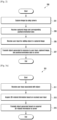
- FIG. 2 is a flowchart of a method for generating an object based on an augmented reality interface according to an example not explicitly disclosing all the features of the claims.
- a processor 120 of an electronic device 101 captures an image by using a camera module 180.
- the processor 120 may activate the camera 180 and capture a still image through the activated camera 180.
- the processor 120 receives the captured image and position and orientation data associated with the captured image.
- the processor 120 receives the position data associated with the captured image by using a position sensor (e.g., the sensor module 176 of FIG. 1 ) and also receives the orientation data associated with the captured image by using a motion sensor (e.g., the sensor module 176 of FIG. 1 ).
- the position data includes data on coordinates where the electronic device 101 is located, and the orientation data includes data on a direction that the camera 180 of the electronic device 101 is facing.
- the electronic device 101 may implement an AR interface, based on the captured image and the position and orientation data associated with the captured image.
- the processor 120 receives a user input (e.g., a stylus pen input) for adding an object to the captured image.
- a user input e.g., a stylus pen input
- the processor 120 may receive a user input through an input device 150, based on the implemented AR interface.
- This user input includes a touch input for generating an object (e.g., content).
- this object includes text, and may further include a symbol, a geometric form, or an image.
- the processor 120 transmits the object generated in response to the user input, the captured image, the position data, and the orientation data to a server 108.
- the processor 120 may store the generated object in a memory 130.
- the processor 120 may transmit the generated object, the image captured at step 201, and the position/orientation data received at step 203 to the server 108 at least in part.
- the electronic device 101 captures a certain image through the camera 180 and receives position and orientation data associated with the captured image. Then, the electronic device 101 may implement an AR interface, based on the captured image, the received position data, and the received orientation data. In addition, the electronic device 101 may receive a user input through the AR interface and then generate an object in response to the received user input. In addition, the electronic device 101 may store the generated object in the memory 130 and transmit the generated object, the captured image, the position data, and the orientation data to the server.
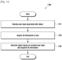
- FIGS. 3A and 3B are flowcharts 301 and 302 of methods for generating a 3D object according to examples not explicitly disclosing all the features of the claims.
- flowchart 301 regards a method for generating a 3D object.
- Flowchart 301 corresponds to the above-described steps 205 and 207 in FIG. 2 .
- a processor 120 of an electronic device 101 receives a user input associated with an object (or content).
- the processor 120 displays a user interface to be used for generating the object through a touch screen display (e.g., the display device 160 of FIG. 1 ) and receives a user input through the user interface.
- the user input includes a touch input by a finger or a touch input by a pen (e.g., a stylus pen).
- the user interface may be an AR interface.
- the processor 120 may activate the camera module 180, capture a certain image through the activated camera, display the captured image through the display, and implement the AR interface based on the captured image.
- the processor 120 acquires 3D-related information for generating the object from the received user input.
- the processor 120 acquires the 3D-related information (e.g., data on coordinates, angle, slope, width, length, height, and/or area) about the object (e.g., text, a geometric form, etc.) to be generated in accordance with the received user input.
- the 3D-related information e.g., data on coordinates, angle, slope, width, length, height, and/or area
- the object e.g., text, a geometric form, etc.
- the processor 120 transmits the object, generated based on the acquired 3D-related information, to the server 108.
- the processor 120 generates the object based on the acquired 3D-related information, displays the generated object on the display 160, and stores the generated object in the memory 130.
- the processor 120 transmits the generated object to an external electronic device (e.g., the server 108).
- the electronic device 101 receives a user input through the display 160 and then acquires 3D-related information for generating an object from the received user input. In addition, the electronic device 101 generates the object based on the acquired 3D-related information, displays the generated object on the display 160, stores the generated object in the memory 130, and transmits the generated object to the server 108.
- flowchart 302 regards a method for generating a 3D object according to an example not explicitly disclosing all the features of the claims.
- Flowchart 302 corresponds to the above-described steps 205 and 207 in FIG. 2 .
- a processor 120 of an electronic device 101 may receive a first user input associated with an object.
- the processor 120 may receive a user input of writing a text object "HELLO" through the touch screen display.
- the processor 120 may identify a geometric form having 3D-related information. For example, the processor 120 may receive an input of constructing a certain geometric form on the display and identify the geometric form from the received input.
- the geometric form may have 3D-related information such as length, height, and slope, so that the processor 120 may also identify the 3D-related information from the identified geometric form.
- step 323 is performed after step 321, step 323 may be alternatively performed before step 321.
- the geometric form having the 3D-related information may be in connection with the first user input received at step 321.
- the input of constructing the geometric form may be received after the first user input associated with the object is received.
- the processor 120 may identify the geometric form having the 3D-related information and then receive the first user input associated with the object. For example, the processor 120 may recognize the first user input in a certain region defined by the geometric form.
- the processor 120 may generate the object in response to the first user input and in consideration of the identified geometric form. For example, considering the 3D-related information of the identified geometric form, the processor 120 may generate a certain object corresponding to the first user input. That is, the generated object may be a 3D object to which the 3D-related information is applied.
- the processor 120 may receive a second user input for the generated object.
- the second user input may be at least one input that directly touches the generated object.
- the second user input may include a drag input.
- the processor 120 may transmit the object to the server 108 in response to the received second user input. For example, when the second user input is a drag input for the object, the processor 120 may move the object in response to the drag input. At this time, the processor 120 may display real-time dragged states of the object through the display 160. In addition, the processor 120 may store information (e.g., a position, coordinates, a slope, a width, a length, etc.) related to the object in the memory 130 and transmit the object to an external electronic device (e.g., the server 108).
- information e.g., a position, coordinates, a slope, a width, a length, etc.
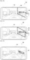
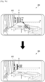
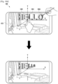
- FIGS. 4A , 4B, 4C, and 4D are illustrations of generating a 3D object according to an example not explicitly disclosing all the features of the claims.
- a processor 120 of an electronic device 400 may display a 3D-based user interface (e.g., the AR interface) through a display 410 such as a touch screen display.
- the 3D-based user interface may include a 3D image, a photograph, a picture, or a real-time preview image being obtained through the camera module 180.
- the processor 120 may receive a user input for generating a 3D object on the 3D-based user interface.
- the processor 120 may receive a first user input of writing a text object 401 (e.g., "HELLO") and display the text object 401 on the display 410.
- This user input may be a user's touch input via a finger or a stylus pen.
- the object generated in response to this user input is not limited to the text object 401.
- the processor 120 may receive a second user input of constructing a certain geometric form 403 (e.g., defining a 3D-based plane in the 3D-based user interface) which surrounds, at least in part, the text object 401. Then, the processor 120 may identify the geometric form 403 from the received second user input, and display the identified geometric form 403 on the display 410.
- This geometric form 403 may have 3D-related information such as data on coordinates, angle, slope, width, length, height, and/or area. Thus, the processor 120 may acquire the 3D-related information from the identified geometric form 403.
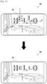
- the processor 120 may receive a third user input of constructing a complete geometric form 404 which completely surrounds the text object 401. Then, the processor 120 may identify the complete geometric form 404 from the received third user input, display the identified geometric form 404 on the display 410, and acquire the 3D-related information from the identified geometric form 404. That is, based on the second and third user inputs, the complete geometric form 404 desired by the user is constructed to surround the text object 401. As a result, the text object 401 such as "HELLO" is contained within the complete geometric form 404.
- the processor 120 may modify the shape of the text object 401, based on the complete geometric form 404. For example, in accordance with the acquired 3D-related information of the complete geometric form 404, the processor 120 may change corresponding 3D-related information of the text object 401.
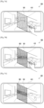
- FIGS. 5A, 5B, 5C , 5D, and 5E are illustrations of generating a 3D object according to an example not explicitly disclosing all the features of the claims.
- a processor 120 of an electronic device 400 may display a 3D-based user interface (e.g., the AR interface) through a display 410 such as a touch screen display.
- the processor 120 may receive a first user input of constructing a certain geometric form 501 that defines, for example, a 3D-based plane in the 3D-based user interface. Then, the processor 120 may identify the geometric form 501 from the received first user input, and display the identified geometric form 501 on the display 410.
- the first user input may be a user's touch input via a finger or a stylus pen.
- the geometric form 501 may have 3D-related information such as data on coordinates, angle, slope, width, length, height, and/or area. Thus, the processor 120 may acquire the 3D-related information from the identified geometric form 501.
- the processor 120 may receive a second user input within the geometric form 501 displayed in the 3D-based user interface.
- the second user input is for generating a 3D object.
- the processor 120 may receive the second user input of writing a text object 503 "HELLO" and display the text object 503 within the geometric form 501 on the display 410.
- the processor 120 may modify the shape of the text object 503, based on the geometric form 501. For example, in accordance with the acquired 3D-related information of the geometric form 501, the processor 120 may change corresponding 3D-related information of the text object 503.
- the processor 120 may receive a third user input 510 associated with the text object 503.
- the third user input may be a drag input for moving the text object 503 in the 3D-based user interface.
- the processor 120 may move the text object 503 in response to the third user input 510.
- the geometric form 501 may disappear from the display 410.
- the processor 120 may display the moved text object 503 on the display 410 after the third user input 510 is released.
- the moved text object 503 may act as one of things contained in the 3D-based user interface.
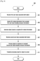
- FIG. 6 is a flowchart 600 of a method for generating a 3D object by using pressure information according to an example not explicitly disclosing all the features of the claims.
- a processor 120 of an electronic device 101 receives a first user input associated with an object.
- the first user input is a touch input and includes pressure information associated with the touch input.
- the processor 120 displays a user interface (e.g., an AR interface) to be used for generating the object through a touch screen display and receives the first user input through the user interface.
- a user interface e.g., an AR interface
- the processor 120 acquires 3D-related information from the received first user input including the pressure information.
- the 3D-related information includes data on coordinates and may further include data on angle, slope, width, length, height, and/or area for generating the object such as text or a geometric form.
- the processor 120 generates the object, based on the acquired 3D-related information.
- the processor 120 displays the generated object on the display 160 and may also store the generated object in a memory 130.
- the processor 120 may receive a second user input associated with the object.
- the second user input may be a touch input and include pressure information associated with the touch input.
- the second user input may be an input for moving or rotating the generated object in the user interface or for modifying the shape of the generated object.
- the processor 120 may process the object in response to the received second user input including the pressure information. For example, the processor 120 may rotate the object displayed on the display 160 in accordance with the second user input including the pressure information.
- a touch position of the second user input may determine a rotation axis of the object, and the pressure information may determine a rotation angle of the object. That is, as a pressure input is increased, the rotation angle may be increased.
- the processor 120 transmits a processing result for the object to the server 108.
- the processor 120 may store information about the rotated object in the memory 130 and transmit such information to an external electronic device (e.g., the server 108).
- FIGS. 7A , 7B , and 7C are illustrations of generating a 3D object by using pressure information according to an embodiment.
- a processor 120 of an electronic device 400 receives a user input associated with an object.
- This user input is a touch input and includes pressure information associated with the touch input. Therefore, upon receiving the user input, the processor 120 extracts the pressure information from the received user input.
- the processor 120 may define in advance a pressure level according to the range of pressure units as shown in Table 1 below.
- Table 1 below shows an example where four pressure levels are defined.
- the processor 120 may detect a certain pressure unit of the received user input by extracting the pressure information and find a certain pressure level corresponding to the detected pressure unit by referring to Table 1 below.
- Pressure Level Pressure Range 1 0 ⁇ pressure unit ⁇ 30 2 30 ⁇ pressure unit ⁇ 60 3 60 ⁇ pressure unit ⁇ 90 4 90 ⁇ pressure unit ⁇ 120
- the processor 120 determines, based on the pressure level, Z-axis coordinate information (i.e., depth information) of an object to be generated. For example, the processor 120 may establish a virtual coordinate system composed of X, Y and Z-axes in a user interface (e.g., an AR interface) displayed on a display 410.
- a user interface e.g., an AR interface
- the processor 120 may determine an X-axis coordinate and a Y-axis coordinate from the position of the touch input and also determine a Z-axis coordinate from the pressure level. For example, in case of a pressure level of "1", the processor 120 may generate and display the object to have a Z-axis coordinate "a" as shown in FIG. 7A .
- the user input for generating the text object "HELLO” may have different pressure levels for respective letters of "HELLO". For example, when a letter “H” is inputted with a pressure level of "1” and then a letter “E” is inputted with a pressure level of "2", the processor 120 may generate and display the letter “H” to have a Z-axis coordinate "a” and also generate and display the letter “E” to have a Z-axis coordinate "0".
- the processor 120 may generate and display the letters "H", “L” and “O” to have a Z-axis coordinate "b” and also generate and display the letters "E” and "L” to have a Z-axis coordinate "0".
- the object generated in response to a user input having a certain pressure level has a depth determined according to the pressure level when displayed in the user interface.
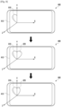
- FIG. 8 is an illustration of generating a 3D object by using pressure information according to an example not explicitly disclosing all the features of the claims.
- a processor 120 of an electronic device 400 may receive a user input associated with an object.
- This user input may be a touch input and include pressure information associated with the touch input. Therefore, upon receiving the user input, the processor 120 may extract the pressure information from the received user input.
- an input of drawing a left portion 810 of the heart form and an input of drawing a right portion 820 of the heart form may have different pressure levels.
- the processor 120 may calculate a difference in pressure level between both inputs and, based on the calculated difference, determine a rotation angle of the heart form.
- Table 2 Difference in Pressure Level Rotation Angle 0 0° 1 30° 2 60° 3 90°
- the processor 120 may determine the rotation angle as 30° by referring to Table 2 above. Then, the processor 120 may rotate one portion of the heart form having the greater pressure level by the determined rotation angle. That is, the right portion 820 of the heart form having the greater pressure level is rotated by 30°.
- the object generated in response to user inputs having different pressure levels may be partially rotated according to a difference in the pressure level when displayed in the user interface.
- FIG. 9 is an illustration of generating a 3D object by using pressure information according to an example not explicitly disclosing all the features of the claims.
- a processor 120 of an electronic device 400 may receive a user input for generating a text object "HELLO”, generate the text object "HELLO" in response to the received user input, and display the generated text object on a display 410.
- the depth of the text object may vary according to pressure information of the received user input.
- a first exemplary text object 910 may have a lower depth according to a pressure level of "1".
- a second exemplary text object 920 may have a middle depth according to a pressure level of "2”
- a third exemplary text object 930 may have a higher depth according to a pressure level of "3”.
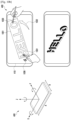
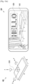
- FIGS. 10A , 10B , 10C , and 10D are illustrations of rotating a 3D object in response to an additional user input according to an example not explicitly disclosing all the features of the claims.
- a processor 120 of an electronic device 400 may establish a virtual coordinate system composed of X, Y and Z-axes in a user interface (e.g., an AR interface) displayed on a display 410.
- a user interface e.g., an AR interface
- the X-axis may be set to correspond to the length A of the electronic device 400
- the Y-axis may be set to correspond to the width B of the electronic device 400
- the Z-axis may be set to correspond to a vertical direction from the display 410.
- the processor 120 displays an object on the display 410. Then, the processor 120 may receive a user input for the displayed object and rotate the object at least in part in response to the received user input.
- the processor 120 displays a text object 1001 (e.g., "HELLO" on the display 410. Then, the processor 120 may receive a multi-touch input including a first user input 1011 and a second user input 1013 with respect to the text object 1001.
- the first user input 1011 may be a finger touch input
- the second user input 1013 may be a pen touch input.
- the processor 120 may determine a rotation axis of the object, based on the first user input 1011, and also determine a rotation direction of the object, based on the second user input 1013. For example, when the first user input 1011 is detected from the left end (i.e., a letter "H") of the object "HELLO", and when the second user input 1013 is detected from the right end (i.e., a letter "O") of the object, the processor 120 may determine the rotation axis of the object as the Y-axis 1010 passing the left end of the object, based on the first user input 1011, and also determine the rotation direction of the object as the rightward direction on the rotation axis, based on the second user input 1013.
- a rotation angle may be determined in proportion to time duration of the second user input 1013 or a pressure level of the second user input 1013.
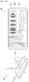
- the processor 120 may determine the rotation axis of the object as the X-axis 1020 passing the lower end of the object, based on the first user input 1021, and also determine the rotation direction of the object as the downward direction on the rotation axis, based on the second user input 1023.
- a rotation angle may be determined in proportion to time duration of the second user input 1023 or a pressure level of the second user input 1023.
- the processor 120 may receive a multi-touch input including a first user input 1031 such as a finger touch input and a second user input 1033 such as a pen drag input. Then, the processor 120 may determine a rotation axis of the object, based on the first user input 1031, and also determine a rotation direction of the object, based on the second user input 1033.
- a first user input 1031 such as a finger touch input
- a second user input 1033 such as a pen drag input.
- the processor 120 may determine a rotation axis of the object, based on the first user input 1031, and also determine a rotation direction of the object, based on the second user input 1033.
- the processor 120 may determine the rotation axis of the object as the Z-axis 1030 near the left end of the object, based on the first user input 1031, and also determine the rotation direction 1032 of the object according to the second user input 1033 (i.e., a dragging direction).
- the processor 120 may receive a multi-touch input including a first user input 1041 such as a finger touch input and a second user input 1043 such as a pen touch input with respect to a predetermined single region 1040 in the object 1001. In this case, the processor 120 may linearly move the displayed object 1001 in response to the received multi-touch input.
- the processor 120 may linearly move the object 1001 along the Z-axis, that is, adjust the depth of the object.
- a moving distance or adjusted depth of the object may be determined in proportion to time duration of both the first and second user inputs 1041 and 1043 or a pressure level of at least one of the first and second user inputs 1041 and 1043.
- the processor 120 may receive a multi-touch input including a first user input 1051 such as a finger touch input and a second user input 1053 such as a pen touch input. Then, the processor 120 may determine a rotation axis of the object 1001, based on the first user input 1051, and also determine a rotation direction of the object, based on the second user input 1053.
- a first user input 1051 such as a finger touch input
- a second user input 1053 such as a pen touch input.
- the processor 120 may determine a rotation axis of the object 1001, based on the first user input 1051, and also determine a rotation direction of the object, based on the second user input 1053.
- the processor 120 may determine the rotation axis of the object as the Y-axis 1030 passing the inside point of the object, based on the first user input 1051, and also determine the rotation direction of the object as the rightward direction on the rotation axis, based on the second user input 1053.
- a rotation angle may be determined in proportion to time duration of the second user input 1053 or a pressure level of the second user input 1053.
- FIG. 11 is a flowchart 1100 of a method for generating a 3D object by using pen tilt information according to an example not explicitly disclosing all the features of the claims.
- a processor 120 of an electronic device 101 may receive a user input associated with an object.
- the user input may be a touch input by a stylus pen.
- the processor 120 may acquire tilt information of the pen.
- the processor 120 may detect the tilt information of the pen, based on electromagnetic waves that change according to a tilt of the pen.
- the pen may have a sensor for detecting the tilt information thereof and acquire the tilt information through the sensor. Therefore, the processor 120 may receive the tilt information of the pen from the pen.
- the processor 120 may generate an object, based on both the received user input and the acquired tilt information of the pen. For example, the processor 120 may determine a direction and slope of the object, based on the tilt information of the pen. Then, the processor 120 may display, on a display, the object to which the determined direction and slope are applied.
- FIGS. 12A , 12B , and 12C are illustrations of generating a 3D object by using pen tilt information according to an example not explicitly disclosing all the features of the claims.
- a processor 120 of an electronic device 400 may establish a virtual coordinate system composed of X, Y and Z-axes in a user interface (e.g., an AR interface) displayed on a display 410.
- a user interface e.g., an AR interface
- the X-axis may be set to correspond to the length A of the electronic device 400
- the Y-axis may be set to correspond to the width B of the electronic device 400
- the Z-axis may be set to correspond to a vertical direction from the display 410.
- the processor 120 may display an object 1201 (e.g., a text object "HELLO") on the display 410. Then, the processor 120 may receive a user input by a pen 1210 for the displayed object 1201, acquire tilt information of the pen 1210, and modify the object on the basis of the acquired tilt information.
- an object 1201 e.g., a text object "HELLO”
- the processor 120 may receive a user input by a pen 1210 for the displayed object 1201, acquire tilt information of the pen 1210, and modify the object on the basis of the acquired tilt information.
- the processor 120 may display the object 1201 without any tilt.
- the processor 120 may display a text object 1203 "HELLO" to have a tilt of ⁇ ° from the X-axis 1221.
- the processor 120 may display a text object 1205 "HELLO" to have a tilt of ⁇ ° from the Y-axis 1223.
- an electronic device includes a housing; a touch screen display disposed within the housing and exposed through at least a portion of the housing; a camera; a wireless communication circuit disposed within the housing; a position sensor; a motion sensor; a processor disposed within the housing and operatively connected to the display, the camera, the wireless communication circuit, the position sensor, and the motion sensor; and a memory disposed within the housing and operatively connected to the processor.
- the memory stores instructions causing, upon execution, the processor to capture an image by using the camera, to receive the captured image from the camera, to receive position data associated with the captured image from the position sensor, to receive orientation data associated with the captured image from the motion sensor, to receive a user input for adding an object to the captured image through the display, and to transmit the object, the captured image, the position data, and the orientation data to an external server through the wireless communication circuit.
- the processor may receive the user input using a stylus pen.
- the object includes text, and may further include at least one of a symbol, a geometric form, or an image.
- the processor may receive a first user input of constructing a geometric form on the captured image, and receive a second user input of writing text at least partially overlapped with the geometric form on the captured image.
- the processor may change a direction of the text in accordance with the geometric form, and transmit information about the changed direction to the server.
- the processor may receive a third user input of moving the text in the captured image, and display the moved text on the display without displaying the geometric form.
- the processor may identify three-dimensional (3D)-related information corresponding to the geometric form, and change the direction of the text, based on the identified 3D-related information.
- the 3D-related information may include data on at least one of coordinates, angle, slope, width, length, height, or area, which corresponds to the geometric form.
- the processor may receive a multi-touch input, and rotate the object at least in part, based on the received multi-touch input.
- the multi-touch input may include a first touch input for determining a rotation axis of the object, and a second touch input for determining a rotation direction of the object.
- the processor may receive tilt information of the stylus pen from the stylus pen, and rotate the object at least in part, based on the received tilt information.
- the electronic device further includes a pressure sensor, and the processor receives pressure information associated with the user input from the pressure sensor, and generates the object, based on the received pressure information.
- the processor may generate the object in accordance with the received user input, and store the generated object in the memory.
- the processor may receive an image, position data associated with the image, and orientation data associated with the image from a second external electronic device including a display and a camera via the network interface, and transmit the object to the second external electronic device via the network interface such that the object is displayed on the display of the second external electronic device, wherein the orientation data is applied to the displayed object.
- the electronic device may be one of various types of electronic devices.
- the electronic devices may include, for example, a portable communication device (e.g., a smart phone), a computer device, a portable multimedia device, a portable medical device, a camera, a wearable device, or a home appliance.
- a portable communication device e.g., a smart phone
- a computer device e.g., a laptop, a desktop, a smart phone
- portable multimedia device e.g., a portable multimedia device
- portable medical device e.g., a portable medical device
- camera e.g., a camera
- a wearable device e.g., a smart watch
- home appliance e.g., a smart bracelet
- module may include a unit implemented in hardware, software, or firmware, and may be interchangeably used with other terms, for example, “logic”, “logic block”, “part”, and “circuitry”.
- the term “module” may indicate a single integral component, or a minimum unit or part thereof, adapted to perform one or more functions.
- the term “module” may be implemented in a form of an application-specific integrated circuit (ASIC).
- ASIC application-specific integrated circuit
- Various embodiments as set forth herein may be implemented as software (e.g., the program 140) including one or more instructions that are stored in a storage medium (e.g., internal memory 136 or external memory 138) that is readable by a machine (e.g., the electronic device 101).
- a processor e.g., the processor 120
- the one or more instructions may include a code generated by a complier or a code executable by an interpreter.
- the machine-readable storage medium may be provided in the form of a non-transitory storage medium.
- non-transitory simply indicates that the storage medium is a tangible device, and does not include a signal (e.g., an electromagnetic wave), but this term does not differentiate between where data is semi-permanently stored in the storage medium and where the data is temporarily stored in the storage medium.
- a method according to an embodiment of the present disclosure may be included and provided in a computer program product.
- the computer program product may be traded as a product between a seller and a buyer.
- the computer program product may be distributed in the form of a machine-readable storage medium (e.g., compact disc read only memory (CD-ROM)), or be distributed (e.g., downloaded or uploaded) online via an application store (e.g., Play StoreTM), or between two user devices (e.g., smart phones) directly. If distributed online, at least part of the computer program product may be temporarily generated or at least temporarily stored in the machine-readable storage medium, such as memory of the manufacturer's server, a server of the application store, or a relay server.
- CD-ROM compact disc read only memory
- an application store e.g., Play StoreTM
- two user devices e.g., smart phones
- each component e.g., a module or a program of the above-described components may include a single entity or multiple entities. One or more of the above-described components may be omitted, or one or more other components may be added. Alternatively or additionally, a plurality of components (e.g., modules or programs) may be integrated into a single component. In such a case, the integrated component may still perform one or more functions of each of the plurality of components in the same or similar manner as they are performed by a corresponding one of the plurality of components before the integration. Operations performed by the module, the program, or another component may be carried out sequentially, in parallel, repeatedly, or heuristically, or one or more of the operations may be executed in a different order or omitted, or one or more other operations may be added.
Landscapes
- Engineering & Computer Science (AREA)
- Theoretical Computer Science (AREA)
- General Engineering & Computer Science (AREA)
- General Physics & Mathematics (AREA)
- Physics & Mathematics (AREA)
- Human Computer Interaction (AREA)
- Signal Processing (AREA)
- Multimedia (AREA)
- Computer Networks & Wireless Communication (AREA)
- User Interface Of Digital Computer (AREA)
- Architecture (AREA)
- Computer Graphics (AREA)
- Computer Hardware Design (AREA)
- Software Systems (AREA)
Claims (6)
- Elektronische Vorrichtung (101), die Folgendes umfasst:ein Gehäuse;ein Touchscreen-Display (160), das innerhalb des Gehäuses angeordnet ist und durch mindestens einen Teil des Gehäuses freiliegt;eine Kamera (180);eine drahtlose Kommunikationsschaltung (190), die innerhalb des Gehäuses angeordnet ist;einen Positionssensor;einen Bewegungssensor;einen Drucksensor;einen Prozessor (120), der innerhalb des Gehäuses angeordnet ist und mit dem Display, der Kamera, der drahtlosen Kommunikationsschaltung, dem Positionssensor, dem Bewegungssensor und dem Drucksensor wirkverbunden ist; undeinen Speicher (130), der innerhalb des Gehäuses angeordnet ist und mit dem Prozessor wirkverbunden ist,wobei der Speicher so konfiguriert ist, dass er Anweisungen speichert, die den Prozessor bei der Ausführung zu Folgendem veranlassen:Aufnehmen (201) eines Bildes unter Verwendung der Kamera,Empfangen (203) des aufgenommenen Bildes von der Kamera,Empfangen (203) von Positionsdaten, die mit dem aufgenommenen Bild assoziiert sind, von dem Positionssensor,Empfangen (203) von Orientierungsdaten, die mit dem aufgenommenen Bild assoziiert sind, von dem Bewegungssensor,Empfangen (323, 501) einer ersten Benutzereingabe zum Konstruieren einer geometrischen Form auf dem aufgenommenen Bild,Empfangen (205, 325, 503) einer zweiten Benutzereingabe zum Schreiben von Text, der sich zumindest teilweise mit der geometrischen Form auf dem aufgenommenen Bild überlappt, über das Display, wobei der Text eine Vielzahl von Buchstaben umfasst und wobei die zweite Benutzereingabe eine Berührungseingabe ist und Druckinformationen enthält, die mit der Berührungseingabe assoziiert sind,Ändern (327) einer Richtung des Textes in Übereinstimmung mit der geometrischen Form,Extrahieren (603) der Druckinformationen aus der empfangenen zweiten Benutzereingabe und Finden von Druckpegeln, die mit der zweiten Benutzereingabe assoziiert sind,Bestimmen von Tiefeninformationen des Objekts, das dem Bild hinzugefügt werden soll, basierend auf den Druckpegeln, wobei die Tiefeninformationen für jeden der Vielzahl von Buchstaben des Textes basierend auf den Druckinformationen bestimmt werden, die für jeden der Vielzahl von Buchstaben des Textes empfangen werden,Erzeugen und Anzeigen jedes Buchstabens der Vielzahl von Buchstaben des Textes basierend auf den bestimmten Tiefeninformationen für jeden der Vielzahl von Buchstaben,
undÜbertragen (207, 315, 611) des Objekts, des aufgenommenen Bildes, der Positionsdaten und der Orientierungsdaten über die drahtlose Kommunikationsschaltung an einen externen Server. - Elektronische Vorrichtung nach Anspruch 1, wobei die Anweisungen den Prozessor bei der Ausführung ferner veranlassen, die zweite Benutzereingabe unter Verwendung eines Stylus-Stiftes zu empfangen,
wobei das Objekt ferner ein Symbol, eine geometrische Form und/oder ein Bild enthält. - Elektronische Vorrichtung nach Anspruch 1, wobei die Anweisungen den Prozessor bei der Ausführung ferner zu Folgendem veranlassen:Empfangen einer dritten Benutzereingabe zum Bewegen des Textes in dem aufgenommenen Bild, undAnzeigen des bewegten Textes auf dem Display, ohne die geometrische Form anzuzeigen.
- Elektronische Vorrichtung nach Anspruch 1, wobei die Anweisungen den Prozessor bei der Ausführung ferner zu Folgendem veranlassen:Identifizieren dreidimensionaler, 3D-bezogener Informationen, die der geometrischen Form entsprechen, undÄndern der Richtung des Textes basierend auf den identifizierten 3D-bezogenen Informationen,wobei die 3D-bezogenen Informationen Daten über die Koordinaten, den Winkel, die Neigung, die Breite, die Länge, die Höhe und/oder die Fläche enthalten, die der geometrischen Form entsprechen.
- Elektronische Vorrichtung nach Anspruch 1, wobei die Anweisungen den Prozessor bei der Ausführung ferner zu Folgendem veranlassen:Empfangen einer Multi-Touch-Eingabe, undDrehen des Objekts zumindest teilweise, basierend auf der empfangenen Multi-Touch-Eingabe,wobei die Multi-Touch-Eingabe eine erste Berührungseingabe zum Bestimmen einer Drehachse des Objekts und eine zweite Berührungseingabe zum Bestimmen einer Drehrichtung des Objekts enthält.
- Elektronische Vorrichtung nach Anspruch 2, wobei die Anweisungen den Prozessor bei der Ausführung ferner zu Folgendem veranlassen:Empfangen von Neigungsinformationen des Stylus-Stiftes von dem Stylus-Stift, undDrehen des Objekts zumindest teilweise, basierend auf den empfangenen Neigungsinformationen.
Applications Claiming Priority (2)
| Application Number | Priority Date | Filing Date | Title |
|---|---|---|---|
| KR1020180067425A KR20190140657A (ko) | 2018-06-12 | 2018-06-12 | 오브젝트를 생성하는 전자장치 및 시스템 |
| PCT/KR2019/007009 WO2019240467A1 (en) | 2018-06-12 | 2019-06-11 | Electronic device and system for generating object |
Publications (3)
| Publication Number | Publication Date |
|---|---|
| EP3776158A1 EP3776158A1 (de) | 2021-02-17 |
| EP3776158A4 EP3776158A4 (de) | 2021-05-26 |
| EP3776158B1 true EP3776158B1 (de) | 2025-02-12 |
Family
ID=68764936
Family Applications (1)
| Application Number | Title | Priority Date | Filing Date |
|---|---|---|---|
| EP19818676.9A Active EP3776158B1 (de) | 2018-06-12 | 2019-06-11 | Elektronisches gerät und system zur erzeugung von objekten |
Country Status (5)
| Country | Link |
|---|---|
| US (1) | US11334230B2 (de) |
| EP (1) | EP3776158B1 (de) |
| KR (2) | KR20190140657A (de) |
| CN (1) | CN112262364B (de) |
| WO (1) | WO2019240467A1 (de) |
Families Citing this family (5)
| Publication number | Priority date | Publication date | Assignee | Title |
|---|---|---|---|---|
| KR102629412B1 (ko) | 2019-01-04 | 2024-01-26 | 삼성전자주식회사 | 외부 장치의 콘텐트를 편집하는 전자 장치 및 방법 |
| KR102743763B1 (ko) * | 2019-02-11 | 2024-12-17 | 삼성전자주식회사 | 가상 현실 유저 인터페이스를 제공하기 위한 전자 장치 및 그의 동작 방법 |
| TWI710932B (zh) * | 2019-12-30 | 2020-11-21 | 宏碁股份有限公司 | 主動式觸控筆及其偵測方法 |
| US12511037B1 (en) * | 2020-10-26 | 2025-12-30 | Apple Inc. | Method and device for typing visualization |
| US12256059B2 (en) | 2023-05-09 | 2025-03-18 | T-Mobile Usa, Inc. | Stimulus-responsive depth-changing display |
Citations (1)
| Publication number | Priority date | Publication date | Assignee | Title |
|---|---|---|---|---|
| US20120134588A1 (en) * | 2010-11-29 | 2012-05-31 | Microsoft Corporation | Rectification of characters and text as transform invariant low-rank textures |
Family Cites Families (25)
| Publication number | Priority date | Publication date | Assignee | Title |
|---|---|---|---|---|
| EP1821182B1 (de) * | 2004-10-12 | 2013-03-27 | Nippon Telegraph And Telephone Corporation | 3d-zeigeverfahren, 3d-anzeigesteuerverfahren, 3d-zeigeeinrichtung, 3d-anzeigesteuereinrichtung, 3d-zeigeprogramm und 3d-anzeigesteuerprogramm |
| KR100790960B1 (ko) * | 2007-10-16 | 2008-01-03 | 주식회사 모비더스 | 플래시 이미지 기반 내장형 그리기 데이터를 생성하는이동기기 및 그 방법 |
| KR101528848B1 (ko) | 2008-11-26 | 2015-06-15 | 엘지전자 주식회사 | 휴대단말기 및 그 제어방법 |
| JP2011053974A (ja) * | 2009-09-02 | 2011-03-17 | Sony Corp | 操作制御装置、操作制御方法およびコンピュータプログラム |
| KR101096392B1 (ko) | 2010-01-29 | 2011-12-22 | 주식회사 팬택 | 증강 현실 제공 시스템 및 방법 |
| CN102375972A (zh) | 2010-08-23 | 2012-03-14 | 谢铮 | 一种分布式的基于可移动设备的增强现实平台 |
| KR20120067421A (ko) | 2010-12-16 | 2012-06-26 | 고스트리트(주) | 증강현실 지능형 모바일 장치 |
| US20130117698A1 (en) * | 2011-10-31 | 2013-05-09 | Samsung Electronics Co., Ltd. | Display apparatus and method thereof |
| KR101847917B1 (ko) | 2011-12-05 | 2018-04-12 | 엘지전자 주식회사 | 이동 단말기 및 그것의 제어 방법 |
| US20130147933A1 (en) | 2011-12-09 | 2013-06-13 | Charles J. Kulas | User image insertion into a text message |
| KR102023008B1 (ko) * | 2012-12-10 | 2019-09-19 | 엘지전자 주식회사 | 음성-텍스트 변환 디스플레이 장치 및 그 방법 |
| US10509533B2 (en) * | 2013-05-14 | 2019-12-17 | Qualcomm Incorporated | Systems and methods of generating augmented reality (AR) objects |
| KR102222336B1 (ko) * | 2013-08-19 | 2021-03-04 | 삼성전자주식회사 | 맵 화면을 디스플레이 하는 사용자 단말 장치 및 그 디스플레이 방법 |
| US9690370B2 (en) * | 2014-05-05 | 2017-06-27 | Immersion Corporation | Systems and methods for viewport-based augmented reality haptic effects |
| KR20160012410A (ko) * | 2014-07-24 | 2016-02-03 | 삼성전자주식회사 | 전자 장치 및 이의 출력 제어 방법 |
| JP6269537B2 (ja) * | 2015-03-06 | 2018-01-31 | 京セラドキュメントソリューションズ株式会社 | 表示入力装置、それを備えた画像形成装置、表示入力装置の制御方法およびプログラム |
| KR102399764B1 (ko) * | 2015-09-22 | 2022-05-19 | 삼성전자 주식회사 | 전자 장치 및 촬영 방법 |
| KR20180000009A (ko) * | 2016-06-21 | 2018-01-02 | 한양대학교 에리카산학협력단 | 증강현실 생성 펜 및 이를 이용한 증강현실 제공 시스템 |
| KR102544780B1 (ko) * | 2016-07-04 | 2023-06-19 | 삼성전자주식회사 | 필기 입력에 따른 사용자 인터페이스 제어 방법 및 이를 구현한 전자 장치 |
| KR102580327B1 (ko) | 2016-09-09 | 2023-09-19 | 삼성전자주식회사 | 전자 장치 및 전자 장치의 제어 방법 |
| KR101756948B1 (ko) | 2016-09-12 | 2017-07-12 | 대연화학(주) | 전자칠판 장치 |
| US10296091B2 (en) * | 2016-10-13 | 2019-05-21 | Immersion Corporation | Contextual pressure sensing haptic responses |
| US10254941B2 (en) * | 2017-06-29 | 2019-04-09 | Best Apps, Llc | Computer aided systems and methods for creating custom products |
| DK180470B1 (en) * | 2017-08-31 | 2021-05-06 | Apple Inc | Systems, procedures, and graphical user interfaces for interacting with augmented and virtual reality environments |
| US11017258B2 (en) * | 2018-06-05 | 2021-05-25 | Microsoft Technology Licensing, Llc | Alignment of user input on a screen |
-
2018
- 2018-06-12 KR KR1020180067425A patent/KR20190140657A/ko not_active Ceased
-
2019
- 2019-06-11 EP EP19818676.9A patent/EP3776158B1/de active Active
- 2019-06-11 US US16/437,892 patent/US11334230B2/en active Active
- 2019-06-11 CN CN201980039047.XA patent/CN112262364B/zh active Active
- 2019-06-11 WO PCT/KR2019/007009 patent/WO2019240467A1/en not_active Ceased
-
2024
- 2024-06-03 KR KR1020240072686A patent/KR102817054B1/ko active Active
Patent Citations (1)
| Publication number | Priority date | Publication date | Assignee | Title |
|---|---|---|---|---|
| US20120134588A1 (en) * | 2010-11-29 | 2012-05-31 | Microsoft Corporation | Rectification of characters and text as transform invariant low-rank textures |
Also Published As
| Publication number | Publication date |
|---|---|
| EP3776158A1 (de) | 2021-02-17 |
| KR20190140657A (ko) | 2019-12-20 |
| EP3776158A4 (de) | 2021-05-26 |
| WO2019240467A1 (en) | 2019-12-19 |
| CN112262364B (zh) | 2025-01-17 |
| US20190377482A1 (en) | 2019-12-12 |
| KR20240084532A (ko) | 2024-06-13 |
| KR102817054B1 (ko) | 2025-06-05 |
| US11334230B2 (en) | 2022-05-17 |
| CN112262364A (zh) | 2021-01-22 |
Similar Documents
| Publication | Publication Date | Title |
|---|---|---|
| US11416080B2 (en) | User intention-based gesture recognition method and apparatus | |
| US11209865B2 (en) | Method for providing image using foldable display and electronic device for supporting the same | |
| EP3570144B1 (de) | Elektronische vorrichtung zur bereitstellung von vr/ar-inhalt | |
| EP3776158B1 (de) | Elektronisches gerät und system zur erzeugung von objekten | |
| US10754546B2 (en) | Electronic device and method for executing function using input interface displayed via at least portion of content | |
| EP3980976B1 (de) | Elektronische vorrichtung zur bereitstellung eines avatars und betriebsverfahren dafür | |
| US20200201515A1 (en) | Method and electronic device for controlling augmented reality device | |
| US11403848B2 (en) | Electronic device and method for generating augmented reality object | |
| US12056286B2 (en) | Electronic device for providing augmented reality service and operating method thereof | |
| US11294452B2 (en) | Electronic device and method for providing content based on the motion of the user | |
| US20250046031A1 (en) | Method and electronic device for arranging ar object | |
| US20200053195A1 (en) | Method for processing incoming call and electronic device for supporting the same | |
| US20220385752A1 (en) | Guide map provision method and electronic device for supporting same | |
| US20190243959A1 (en) | Electronic device and user authentication method thereof | |
| US11189067B2 (en) | Electronic device and content generation method | |
| EP3948482B1 (de) | Elektronisches gerät mit anzeigevorrichtung mit berührungssensor | |
| US11164388B2 (en) | Electronic device and method for providing augmented reality object therefor | |
| US11622097B2 (en) | Apparatus and method for providing point of interest (POI) information in 360 video | |
| US12406406B2 (en) | Electronic device for providing augmented reality mode, and operating method therefor | |
| US12014102B2 (en) | Foldable electronic device for displaying user interface and method therefor |
Legal Events
| Date | Code | Title | Description |
|---|---|---|---|
| STAA | Information on the status of an ep patent application or granted ep patent |
Free format text: STATUS: THE INTERNATIONAL PUBLICATION HAS BEEN MADE |
|
| PUAI | Public reference made under article 153(3) epc to a published international application that has entered the european phase |
Free format text: ORIGINAL CODE: 0009012 |
|
| STAA | Information on the status of an ep patent application or granted ep patent |
Free format text: STATUS: REQUEST FOR EXAMINATION WAS MADE |
|
| 17P | Request for examination filed |
Effective date: 20201112 |
|
| AK | Designated contracting states |
Kind code of ref document: A1 Designated state(s): AL AT BE BG CH CY CZ DE DK EE ES FI FR GB GR HR HU IE IS IT LI LT LU LV MC MK MT NL NO PL PT RO RS SE SI SK SM TR |
|
| AX | Request for extension of the european patent |
Extension state: BA ME |
|
| A4 | Supplementary search report drawn up and despatched |
Effective date: 20210428 |
|
| RIC1 | Information provided on ipc code assigned before grant |
Ipc: G06F 3/0481 20130101AFI20210421BHEP Ipc: G06F 3/00 20060101ALI20210421BHEP Ipc: G06F 3/0346 20130101ALI20210421BHEP Ipc: G06F 3/0354 20130101ALI20210421BHEP Ipc: G06F 3/038 20130101ALI20210421BHEP Ipc: G06F 3/0488 20130101ALI20210421BHEP Ipc: G06F 3/041 20060101ALI20210421BHEP Ipc: G06T 11/20 20060101ALI20210421BHEP Ipc: G06T 19/20 20110101ALI20210421BHEP |
|
| DAV | Request for validation of the european patent (deleted) | ||
| DAX | Request for extension of the european patent (deleted) | ||
| STAA | Information on the status of an ep patent application or granted ep patent |
Free format text: STATUS: EXAMINATION IS IN PROGRESS |
|
| 17Q | First examination report despatched |
Effective date: 20211025 |
|
| GRAP | Despatch of communication of intention to grant a patent |
Free format text: ORIGINAL CODE: EPIDOSNIGR1 |
|
| STAA | Information on the status of an ep patent application or granted ep patent |
Free format text: STATUS: GRANT OF PATENT IS INTENDED |
|
| INTG | Intention to grant announced |
Effective date: 20240930 |
|
| GRAS | Grant fee paid |
Free format text: ORIGINAL CODE: EPIDOSNIGR3 |
|
| GRAA | (expected) grant |
Free format text: ORIGINAL CODE: 0009210 |
|
| STAA | Information on the status of an ep patent application or granted ep patent |
Free format text: STATUS: THE PATENT HAS BEEN GRANTED |
|
| AK | Designated contracting states |
Kind code of ref document: B1 Designated state(s): AL AT BE BG CH CY CZ DE DK EE ES FI FR GB GR HR HU IE IS IT LI LT LU LV MC MK MT NL NO PL PT RO RS SE SI SK SM TR |
|
| REG | Reference to a national code |
Ref country code: GB Ref legal event code: FG4D |
|
| REG | Reference to a national code |
Ref country code: CH Ref legal event code: EP |
|
| REG | Reference to a national code |
Ref country code: DE Ref legal event code: R096 Ref document number: 602019065865 Country of ref document: DE |
|
| REG | Reference to a national code |
Ref country code: IE Ref legal event code: FG4D |
|
| REG | Reference to a national code |
Ref country code: NL Ref legal event code: MP Effective date: 20250212 |
|
| PG25 | Lapsed in a contracting state [announced via postgrant information from national office to epo] |
Ref country code: RS Free format text: LAPSE BECAUSE OF FAILURE TO SUBMIT A TRANSLATION OF THE DESCRIPTION OR TO PAY THE FEE WITHIN THE PRESCRIBED TIME-LIMIT Effective date: 20250512 |
|
| PG25 | Lapsed in a contracting state [announced via postgrant information from national office to epo] |
Ref country code: FI Free format text: LAPSE BECAUSE OF FAILURE TO SUBMIT A TRANSLATION OF THE DESCRIPTION OR TO PAY THE FEE WITHIN THE PRESCRIBED TIME-LIMIT Effective date: 20250212 |
|
| PG25 | Lapsed in a contracting state [announced via postgrant information from national office to epo] |
Ref country code: PL Free format text: LAPSE BECAUSE OF FAILURE TO SUBMIT A TRANSLATION OF THE DESCRIPTION OR TO PAY THE FEE WITHIN THE PRESCRIBED TIME-LIMIT Effective date: 20250212 |
|
| PGFP | Annual fee paid to national office [announced via postgrant information from national office to epo] |
Ref country code: DE Payment date: 20250520 Year of fee payment: 7 |
|
| PG25 | Lapsed in a contracting state [announced via postgrant information from national office to epo] |
Ref country code: ES Free format text: LAPSE BECAUSE OF FAILURE TO SUBMIT A TRANSLATION OF THE DESCRIPTION OR TO PAY THE FEE WITHIN THE PRESCRIBED TIME-LIMIT Effective date: 20250212 |
|
| REG | Reference to a national code |
Ref country code: LT Ref legal event code: MG9D |
|
| PG25 | Lapsed in a contracting state [announced via postgrant information from national office to epo] |
Ref country code: NO Free format text: LAPSE BECAUSE OF FAILURE TO SUBMIT A TRANSLATION OF THE DESCRIPTION OR TO PAY THE FEE WITHIN THE PRESCRIBED TIME-LIMIT Effective date: 20250512 Ref country code: IS Free format text: LAPSE BECAUSE OF FAILURE TO SUBMIT A TRANSLATION OF THE DESCRIPTION OR TO PAY THE FEE WITHIN THE PRESCRIBED TIME-LIMIT Effective date: 20250612 |
|
| PG25 | Lapsed in a contracting state [announced via postgrant information from national office to epo] |
Ref country code: NL Free format text: LAPSE BECAUSE OF FAILURE TO SUBMIT A TRANSLATION OF THE DESCRIPTION OR TO PAY THE FEE WITHIN THE PRESCRIBED TIME-LIMIT Effective date: 20250212 |
|
| PG25 | Lapsed in a contracting state [announced via postgrant information from national office to epo] |
Ref country code: HR Free format text: LAPSE BECAUSE OF FAILURE TO SUBMIT A TRANSLATION OF THE DESCRIPTION OR TO PAY THE FEE WITHIN THE PRESCRIBED TIME-LIMIT Effective date: 20250212 |
|
| PG25 | Lapsed in a contracting state [announced via postgrant information from national office to epo] |
Ref country code: PT Free format text: LAPSE BECAUSE OF FAILURE TO SUBMIT A TRANSLATION OF THE DESCRIPTION OR TO PAY THE FEE WITHIN THE PRESCRIBED TIME-LIMIT Effective date: 20250612 Ref country code: LV Free format text: LAPSE BECAUSE OF FAILURE TO SUBMIT A TRANSLATION OF THE DESCRIPTION OR TO PAY THE FEE WITHIN THE PRESCRIBED TIME-LIMIT Effective date: 20250212 |
|
| PG25 | Lapsed in a contracting state [announced via postgrant information from national office to epo] |
Ref country code: BG Free format text: LAPSE BECAUSE OF FAILURE TO SUBMIT A TRANSLATION OF THE DESCRIPTION OR TO PAY THE FEE WITHIN THE PRESCRIBED TIME-LIMIT Effective date: 20250212 Ref country code: GR Free format text: LAPSE BECAUSE OF FAILURE TO SUBMIT A TRANSLATION OF THE DESCRIPTION OR TO PAY THE FEE WITHIN THE PRESCRIBED TIME-LIMIT Effective date: 20250513 |
|
| REG | Reference to a national code |
Ref country code: AT Ref legal event code: MK05 Ref document number: 1766671 Country of ref document: AT Kind code of ref document: T Effective date: 20250212 |
|
| PG25 | Lapsed in a contracting state [announced via postgrant information from national office to epo] |
Ref country code: SE Free format text: LAPSE BECAUSE OF FAILURE TO SUBMIT A TRANSLATION OF THE DESCRIPTION OR TO PAY THE FEE WITHIN THE PRESCRIBED TIME-LIMIT Effective date: 20250212 |
|
| PG25 | Lapsed in a contracting state [announced via postgrant information from national office to epo] |
Ref country code: SM Free format text: LAPSE BECAUSE OF FAILURE TO SUBMIT A TRANSLATION OF THE DESCRIPTION OR TO PAY THE FEE WITHIN THE PRESCRIBED TIME-LIMIT Effective date: 20250212 |
|
| PG25 | Lapsed in a contracting state [announced via postgrant information from national office to epo] |
Ref country code: DK Free format text: LAPSE BECAUSE OF FAILURE TO SUBMIT A TRANSLATION OF THE DESCRIPTION OR TO PAY THE FEE WITHIN THE PRESCRIBED TIME-LIMIT Effective date: 20250212 |
|
| PG25 | Lapsed in a contracting state [announced via postgrant information from national office to epo] |
Ref country code: IT Free format text: LAPSE BECAUSE OF FAILURE TO SUBMIT A TRANSLATION OF THE DESCRIPTION OR TO PAY THE FEE WITHIN THE PRESCRIBED TIME-LIMIT Effective date: 20250212 |
|
| PG25 | Lapsed in a contracting state [announced via postgrant information from national office to epo] |
Ref country code: AT Free format text: LAPSE BECAUSE OF FAILURE TO SUBMIT A TRANSLATION OF THE DESCRIPTION OR TO PAY THE FEE WITHIN THE PRESCRIBED TIME-LIMIT Effective date: 20250212 |
|
| PG25 | Lapsed in a contracting state [announced via postgrant information from national office to epo] |
Ref country code: EE Free format text: LAPSE BECAUSE OF FAILURE TO SUBMIT A TRANSLATION OF THE DESCRIPTION OR TO PAY THE FEE WITHIN THE PRESCRIBED TIME-LIMIT Effective date: 20250212 Ref country code: CZ Free format text: LAPSE BECAUSE OF FAILURE TO SUBMIT A TRANSLATION OF THE DESCRIPTION OR TO PAY THE FEE WITHIN THE PRESCRIBED TIME-LIMIT Effective date: 20250212 |
|
| PG25 | Lapsed in a contracting state [announced via postgrant information from national office to epo] |
Ref country code: RO Free format text: LAPSE BECAUSE OF FAILURE TO SUBMIT A TRANSLATION OF THE DESCRIPTION OR TO PAY THE FEE WITHIN THE PRESCRIBED TIME-LIMIT Effective date: 20250212 |
|
| PG25 | Lapsed in a contracting state [announced via postgrant information from national office to epo] |
Ref country code: SK Free format text: LAPSE BECAUSE OF FAILURE TO SUBMIT A TRANSLATION OF THE DESCRIPTION OR TO PAY THE FEE WITHIN THE PRESCRIBED TIME-LIMIT Effective date: 20250212 |
|
| REG | Reference to a national code |
Ref country code: DE Ref legal event code: R097 Ref document number: 602019065865 Country of ref document: DE |
|
| PLBE | No opposition filed within time limit |
Free format text: ORIGINAL CODE: 0009261 |
|
| STAA | Information on the status of an ep patent application or granted ep patent |
Free format text: STATUS: NO OPPOSITION FILED WITHIN TIME LIMIT |
|
| REG | Reference to a national code |
Ref country code: CH Ref legal event code: L10 Free format text: ST27 STATUS EVENT CODE: U-0-0-L10-L00 (AS PROVIDED BY THE NATIONAL OFFICE) Effective date: 20251224 |
|
| 26N | No opposition filed |
Effective date: 20251113 |
|
| REG | Reference to a national code |
Ref country code: CH Ref legal event code: H13 Free format text: ST27 STATUS EVENT CODE: U-0-0-H10-H13 (AS PROVIDED BY THE NATIONAL OFFICE) Effective date: 20260127 |
|
| PG25 | Lapsed in a contracting state [announced via postgrant information from national office to epo] |
Ref country code: MC Free format text: LAPSE BECAUSE OF FAILURE TO SUBMIT A TRANSLATION OF THE DESCRIPTION OR TO PAY THE FEE WITHIN THE PRESCRIBED TIME-LIMIT Effective date: 20250212 |
|
| PG25 | Lapsed in a contracting state [announced via postgrant information from national office to epo] |
Ref country code: LU Free format text: LAPSE BECAUSE OF NON-PAYMENT OF DUE FEES Effective date: 20250611 |
|
| GBPC | Gb: european patent ceased through non-payment of renewal fee |
Effective date: 20250611 |
|
| REG | Reference to a national code |
Ref country code: BE Ref legal event code: MM Effective date: 20250630 |