EP3775812B1 - Systeme und verfahren für eine intelligente thermoelement-temperatursonde - Google Patents
Systeme und verfahren für eine intelligente thermoelement-temperatursonde Download PDFInfo
- Publication number
- EP3775812B1 EP3775812B1 EP19774677.9A EP19774677A EP3775812B1 EP 3775812 B1 EP3775812 B1 EP 3775812B1 EP 19774677 A EP19774677 A EP 19774677A EP 3775812 B1 EP3775812 B1 EP 3775812B1
- Authority
- EP
- European Patent Office
- Prior art keywords
- temperature probe
- temperature
- connector
- sample
- measurement
- Prior art date
- Legal status (The legal status is an assumption and is not a legal conclusion. Google has not performed a legal analysis and makes no representation as to the accuracy of the status listed.)
- Active
Links
Images




Classifications
-
- G—PHYSICS
- G01—MEASURING; TESTING
- G01K—MEASURING TEMPERATURE; MEASURING QUANTITY OF HEAT; THERMALLY-SENSITIVE ELEMENTS NOT OTHERWISE PROVIDED FOR
- G01K7/00—Measuring temperature based on the use of electric or magnetic elements directly sensitive to heat ; Power supply therefor, e.g. using thermoelectric elements
- G01K7/02—Measuring temperature based on the use of electric or magnetic elements directly sensitive to heat ; Power supply therefor, e.g. using thermoelectric elements using thermoelectric elements, e.g. thermocouples
- G01K7/14—Arrangements for modifying the output characteristic, e.g. linearising
-
- G—PHYSICS
- G01—MEASURING; TESTING
- G01K—MEASURING TEMPERATURE; MEASURING QUANTITY OF HEAT; THERMALLY-SENSITIVE ELEMENTS NOT OTHERWISE PROVIDED FOR
- G01K15/00—Testing or calibrating of thermometers
- G01K15/005—Calibration
-
- G—PHYSICS
- G01—MEASURING; TESTING
- G01K—MEASURING TEMPERATURE; MEASURING QUANTITY OF HEAT; THERMALLY-SENSITIVE ELEMENTS NOT OTHERWISE PROVIDED FOR
- G01K7/00—Measuring temperature based on the use of electric or magnetic elements directly sensitive to heat ; Power supply therefor, e.g. using thermoelectric elements
- G01K7/02—Measuring temperature based on the use of electric or magnetic elements directly sensitive to heat ; Power supply therefor, e.g. using thermoelectric elements using thermoelectric elements, e.g. thermocouples
- G01K7/023—Measuring temperature based on the use of electric or magnetic elements directly sensitive to heat ; Power supply therefor, e.g. using thermoelectric elements using thermoelectric elements, e.g. thermocouples provided with specially adapted connectors
-
- G—PHYSICS
- G01—MEASURING; TESTING
- G01K—MEASURING TEMPERATURE; MEASURING QUANTITY OF HEAT; THERMALLY-SENSITIVE ELEMENTS NOT OTHERWISE PROVIDED FOR
- G01K2207/00—Application of thermometers in household appliances
- G01K2207/02—Application of thermometers in household appliances for measuring food temperature
Definitions
- thermocouples and more particularly to smart thermocouple temperature probe control systems and methods.
- thermocouple may be used to measure the temperature of food products or environment surfaces.
- the thermocouple may include two wires that are made from different alloys and are welded together at one end, creating a junction. Temperature is measured at the junction. A voltage may be generated based on the temperature experienced at the junction. The temperature may be determined using a lookup table that corresponds change in voltages to temperatures.
- thermocouples there are a variety of types of thermocouples, such as a type-K, type-J, type-T, type-E, and so on. Each type of thermocouple may have different characteristics (e.g., operational temperate range, tolerance range, durability, etc.). Thermocouples may also be used to measure temperature in various applications, such as in industrial and scientific applications.
- a system includes a measurement instrument including a first connector and a control module electrically connected to the first connector.
- the system includes a temperature probe including a shaft and a tip, the shaft having a first end and a second end, a second connector being coupled to the first end, the tip being coupled to the second end and configured to measure a change in temperature of a sample, and the second connector being received by the first connector when the temperature probe is attached to the measurement instrument.
- the system includes a storage module housed within the second connector and configured to store one or more parameters of the temperature probe.
- the control module being configured to: receive the one or more parameters from the storage module; determine a temperature measurement based on a change in voltage; determine a first correction based on the one or more parameters; and determine an adjusted temperature measurement based on the temperature measurement and the first correction.
- a system includes a measurement instrument including a first connector, a control module electrically connected to the first connector, and a display housed on the measurement instrument.
- the system includes a temperature probe including a shaft and a tip, the shaft having a first end and a second end, a second connector being coupled to the first end, the tip being coupled to the second end and configured to measure a change in temperature of a sample, and the second connector being received by the first connector when the temperature probe is attached to the measurement instrument.
- the system includes a storage module housed within the second connector and configured to store one or more parameters of the temperature probe.
- the control module being configured to: receive the one or more parameters from the storage module; prompt a user to select the sample on the display; determine a thermal conductivity of the sample; determine a stable time of the sample; when a period greater than or equal to the stable time has elapsed, determine a temperature measurement based on a change in voltage; and display the temperature measurement on the display.
- a method of determining a temperature includes storing one or more parameters of a temperature probe by a storage module.
- the method includes receiving the one or more parameters from the storage module.
- the method includes determining a temperature measurement based on a change in voltage of the temperature probe.
- the method includes determining a first correction based on the one or more parameters.
- the method includes determining an adjusted temperature measurement based on the temperature measurement and the first correction.
- the method includes displaying the adjusted temperature measurement on a display.
- WO 2014/153035 A1 discloses a method and apparatus for probe calibration.
- US 5 857 777 A discloses a smart temperature sensing device.
- DE 20 2016 102171 U1 discloses an electric plug connection.
- thermocouple system includes a measurement instrument and a temperature probe.
- the thermocouple system may be used to take a temperature measurement of a sample.
- the measurement instrument and the temperature probe may be calibrated together as a single system to prevent inaccurate temperature measurements before the thermocouple system is shipped from a factory. Under some circumstances, the temperature probe may degrade over time and may need to be either replaced with a new temperature probe, or recalibrated to maintain system accuracy.
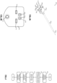
- thermocouple system 100 is used to measure temperature.
- the thermocouple system 100 may be used in the food service industry, for example, to measure internal temperature of food or to measure temperature of equipment surfaces. Monitoring the internal temperature of food may help determine whether the food has been cooked properly and ensure proper food safety and food quality.
- the thermocouple system 100 may also be used in other suitable industries, such as pharmaceutical, oil and gas, power generation, etc. For example, in the pharmaceutical industry, it may be important to monitor temperature of drugs because the effectiveness of some drugs decreases with exposure to cold and heat.
- the thermocouple system 100 includes a measurement instrument 104 and a temperature probe 108.
- the measurement instrument 104 includes a grip 112 that allows a user to grasp onto the measurement instrument 104 securely.
- a status indicator 116 e.g., light emitting diode (LED) or incandescent bulb
- the status indicator 116 may illuminate green to indicate that the measurement instrument 104 is powered on.
- the status indicator 116 may, for example, illuminate blue when the measurement instrument 104 is ready to take a temperature measurement via the temperature probe 108.
- the temperature measurement is a measurement reading of temperature of a sample (e.g., food, surface of equipment, etc.).
- the user may insert the temperature probe 108 into the sample or place it on a surface of the sample.
- the user may depress a button 120 to take the temperature measurement.
- the temperature measurement may be displayed on a display 124, such as a touchscreen, a liquid crystal display (LCD), etc. Additionally or alternatively, the temperature measurement may be displayed on a smart device, such as a smartphone, a tablet, etc.
- the measurement instrument 104 may communicate with the smart device using, for example, Bluetooth protocol or Bluetooth Low Energy (BLE) protocol that is compliant with the BLE specification, including, for example, version 5 of the BLE specification.
- the measurement instrument 104 may be powered with a DC power source (e.g., battery).
- a DC power source e.g., battery
- the measurement instrument 104 includes a first connector 128 that is configured to receive a second connector 132 of the temperature probe 108.
- the temperature probe 108 includes a shaft 136.
- the second connector 132 is coupled to a first end of the shaft 136.
- a tip 140 is coupled to a second end of the shaft 136.
- the first connector 128 and the second connector 132 are discussed in further detail below with reference to FIGs. 2A-2B and 3A-3B , respectively.
- the tip 140 includes a first wire and a second wire that are each made from different alloys.
- the alloy material varies based on the type of temperature probe used.
- the first wire may be Nickel-Chromium and the second wire may be Nickel-Aluminum for a type-K temperature probe.
- the first and second wires may be electrically connected, forming a junction in the tip 140 of the temperature probe 108.
- the junction may be formed, for example, by welding the first and second wires together and potting them in a thermally conductive potting.
- the temperature measurement of the sample is measured at the junction in the tip 140.
- a voltage is generated based on the temperature experienced at the junction.
- a control module 144 may be configured to determine the temperature measurement using one or more lookup tables and/or equations that relate the change in voltages to temperature measurements. Voltage may increase as the temperature increases and vice versa. The control module 144 is discussed in further detail below.
- the first connector 128 has a first surface 204 having a pair of apertures 208, a first slot 212, and a second slot 214.
- the first connector 128 is received in a recess such that the first surface 204 of the first connector 128 is flush with the measurement instrument 104.
- the first connector 128 is fixedly coupled to the measurement instrument 104.
- the first connector 128 may be a female type connector.
- the pair of apertures 208 extend from the first surface 204 of the first connector 128 through the length of the first connector 128.
- a pair of terminals 216 are disposed within the pair of apertures 208.
- the pair of terminals 216 extend from the first surface 204 of the first connector 128 to the control module 144.
- the pair of terminals 216 are electrically connected (e.g., by solder) to the control module 144.
- the pair of terminals 216 are configured to transmit signals and electrical power between the measurement instrument 104 and the temperature probe 108.
- the pair of terminals 216 may be made from alloy, for example, copper alloy, silver alloy, or other suitable electrically conductive materials.
- the first slot 212 and the second slot 214 extend from the first surface 204 of the first connector 128 through the length of the first connector 128.
- the first slot 212 may be a different size than the second slot 214.
- the first slot 212 may be wider than the second slot 214.
- the first slot 212 may be a different size than the second slot 214 so that the user does not improperly connect the temperature probe 108 to the measurement instrument 104.
- the first slot 212 is shown and discussed as having a different size than the second slot 214, the first slot 212 and the second slot 214 may be the same size.
- the first surface 204 of the first connector 128 may include a visual indicator 220 to indicate to the user the type of temperature probe (e.g., type-K, type-J, type-T, type-E, etc.) that may be received by the measurement instrument 104 (via the first connector 128).
- the visual indicator 220 indicates that the measurement instrument 104 (via the first connector 128) receives a type-K temperature probe.
- the visual indicator 220 may be recessed within the first surface 204 of the first connector 128.
- the visual indicator 220 is shown and discussed as indicating the type-K temperature probe, the visual indicator 220 may indicate a type-J, type-T, type-E, or another suitable temperature probe type, such as a thermistor, RTD, etc.
- the second connector 132 has a second surface 304 having a pair of pin connectors 308 protruding from the second surface 304.
- the pair of pin connectors 308 are configured to transmit signals and electrical power between the measurement instrument 104 and the temperature probe 108.
- the pair of pin connectors 308 may be made from alloy, for example, copper alloy, silver alloy, or other suitable electrically conductive materials.
- the pair of pin connectors 308 may be spring-loaded allowing the pair of pin connectors 308 to be in an extended position, a compressed position, or any position between the extended and compressed positions.
- the pair of pin connectors 308 may be in the extended position when the second connector 132 is not connected to the first connector 128.
- the pin connectors 308 may be in the compressed position when the second connector 132 is connected to the first connector 128.
- the second connector 132 may also include a first spade connector 312 and a second spade connector 314.
- the first and second wires extend from the junction in the tip 140 (through the shaft 136) to the second connector 132.
- the first spade connector 312 may be coupled to the first wire and the second spade connector 314 may be coupled to the second wire.
- the first spade connector 312 and the second spade connector 314 protrude from the second surface 304 of the second connector 132.
- the first spade connector 312 and the second spade connector 314 may be made from alloy, for example, corresponding to the material types used in the corresponding type of temperature probe.
- the first spade connector 312 may be Nickel-Chromium and the second spade connector 314 may be Nickel-Aluminum for a type-K temperature probe.
- the second connector 132 is connected to the first connector 128, the first spade connector 312 is received within the first slot 212, the second spade connector 314 is received within the second slot 214, and the pair of pin connectors 308 are coupled to the pair of terminals 216.
- the first spade connector 312 and the second spade connector 314 are configured to transmit signals and electrical power between the measurement instrument 104 and the temperature probe 108.
- the temperature probe 108 (via the second connector 132) may be fastened to the measurement instrument 104 with a fastener 316, such as a screw or clip.
- the fastener 316 securely holds the temperature probe 108 in place (with the measurement instrument 104) as the user may insert and remove the temperature probe 108 from the sample (e.g., food).
- the second connector 132 may be a male type connector.
- a temperature probe may have an accuracy tolerance.
- the temperature probe may be manufactured by various manufactures and must follow American National Standards Institute (ANSI) standards. According to ANSI standards, the temperature probe may have a standard limit accuracy tolerance and a special limit accuracy tolerance.
- the type of wires used e.g., first wire and second wire
- the standard limit accuracy tolerance may be determined when standard grade wires (e.g., first wire and second wire) are used to form the junction.
- the special limit accuracy tolerance may be determined when higher grade wires (e.g., first wire and second wire) are used to form the junction.
- the standard limit accuracy tolerance and special limit accuracy tolerance vary based on the type of temperature probe used.
- the standard limit accuracy tolerance of a type-K temperature probe is plus or minus ( ⁇ ) 4 degrees Fahrenheit (°F), i.e. about 2.2 °C.
- the special limit accuracy tolerance, for example, of a type-K temperature probe is ⁇ 2 °F (about ⁇ 1.1 °C).
- a measurement instrument may also have an accuracy tolerance.
- the accuracy tolerance of the temperature probe and the accuracy tolerance of the measurement instrument may collectively be referred to as system accuracy.
- the system accuracy may be determined, for example, by adding the accuracy tolerance of the temperature probe to the accuracy tolerance of the measurement instrument.
- a temperature probe having an accuracy tolerance of ⁇ 2°F (about ⁇ 1.1 °C) and a measurement instrument having an accuracy tolerance of ⁇ 0.5°F (about 0.3 °C) may have a system accuracy of ⁇ 2.5 °F (about ⁇ 1.4 °C).
- Each temperature probe may have an offset value that is within the accuracy tolerance of the temperature probe.
- the offset value may be determined based on empirical data derived at a factory. For example, the offset value may be a difference between a first observed temperature measurement and an expected temperature measurement. To prevent inaccurate temperature measurements, the measurement instrument may be calibrated based on the offset value of the temperature probe. For example, if it is determined that a temperature probe has an offset value of +1 °F (about 0.5 °C) the measurement instrument may be calibrated with a -1°F (about -0.5 °C) value at the factory to compensate for the offset value of the temperature probe
- the user may replace the original temperature probe with a replacement temperature probe.
- the replacement temperature probe may have a different offset value than the original temperature probe (that was calibrated with the measurement instrument) and the user may not have the equipment necessary to recalibrate the measurement instrument with the offset value of the replacement temperature probe.
- the temperature measurement e.g., with the replacement probe
- the measurement instrument may be calibrated with a +4°F (about +2.2 °C) value to compensate for the offset value at the factory.
- the temperature measurement may be inaccurate by up to +8 °F, i.e. about 4.4 °C (e.g., +4°F from the calibrated measurement instrument and +4 from the replacement temperature probe).
- the offset value of the temperature probe 108 is stored within the temperature probe 108. Storing the offset value of the temperature probe 108 may prevent inaccurate temperature measurements from being measured by the replacement temperature probe.
- the offset value of the temperature probe 108 is stored in a storage module 320.
- the storage module 320 is housed within the second connector 132 and is electrically connected to the pair of pin connectors 308. According to the invention, the storage module 320 transmits (via the pair of pin connectors 308 and the pair of terminals 216) the stored offset value of the temperature probe 108 to the control module 144 when the temperature probe 108 is connected to the measurement instrument 104.
- the control module 144 is configured to receive the offset value of the temperature probe 108 from the storage module 320. According to the invention, the control module 144 adjusts the temperature measurement based on a first correction value.
- the control module 144 may determine the first correction value based on a value that is opposite of the offset value. For example, the control module 144 may determine a first correction value of -3°F (about -1.7 °C) if the temperature probe 108 has an offset value of +3 °F (about +1.7 °C).
- the measurement instrument 104 may display the adjusted temperature measurement on the display 124 or on the smart device.
- the control module 144 may determine the adjusted temperature measurement, for example, by adding the first correction value to the temperature measurement.
- the adjusted temperature measurement may prevent inaccurate temperature measurements when the temperature probe 108 may be replaced as the temperature probe 108 degrades over time.
- the control module 144 may include one or more other modules, such as a BLE module to communicate with the smart device.
- the control module 144 may determine a temperature measurement of +210°F (about 99 °C) at the tip 140.
- the storage module 320 may store an offset value of -2°F (about -1.1 °C) of the temperature probe 108.
- the control module 144 may receive the offset value and determine a first correction value of +2 °F (about +1.1 °C).
- the control module 144 may determine an adjusted temperature measurement of +212°F (about +100 °C). (by adding the first correction value to the temperature measurement).
- the adjusted temperature measurement may be displayed on the display 124 or on the smart device.
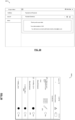
- Control begins with 404 where the control module 144 determines the temperature measurement.
- the control module 144 receives and determines the offset value of the temperature probe 108 from the storage module 320.
- the control module 144 determines the first correction value.
- the control module 144 determines the adjusted temperature measurement.
- the measurement instrument 104 may display the adjusted temperature measurement on the display 124 or on the smart device. While control is shown and discussed as ending, the example of FIG. 4 may be illustrative of one control loop and control may return to 404.
- an offset value of a temperature probe may vary over time based on factors, such as aging of a junction, and/or if the temperature probe may have been exposed to temperatures outside of an operational range.
- the aging of the junction may be, for example, determined based on a usage period of the temperature probe.
- the offset value that has been stored in a storage module may be adjusted (e.g., updated) to compensate for the variation in the offset value over time. As such, the useful life of the temperature probe may be extended.
- the adjusted offset value may be stored in the storage module 320.
- the adjusted offset value may replace the offset value.
- the adjusted offset value may be determined based on empirical data derived at the factory. For example, the adjusted offset value may be a difference between a second observed temperature measurement and the expected temperature measurement.
- the user may send the temperature probe 108 to the factory.
- the adjusted offset value may be determined based on the difference between the second observed temperature measurement and the expected temperature measurement.
- the adjusted offset value may replace the offset value and be stored in the storage module 320 of the temperature probe 108.
- the factory may send the temperature probe 108 back to the user.
- the control module 144 receives the adjusted offset value from the storage module 320.
- the control module 144 determines the adjusted temperature measurement based on the adjusted offset value instead of the offset value.
- thermocouple system may not wait long enough for a temperature measurement to reach a stable temperature, causing an inaccurate temperature measurement to be taken. Under some circumstances, the user may wait too long before determining that the temperature measurement has reached the stable temperature, causing an unnecessary delay.
- the stable temperature is an indication that a tip is able to maintain a consistent voltage (indicative of a consistent temperature measurement) of a sample (e.g., food or surface of environment). As such, a thermocouple system may optimize a period before displaying the temperature measurement (e.g., stable temperature).
- the storage module 320 is configured to store a response time of the temperature probe 108.
- the storage module 320 transmits the response time of the temperature probe 108 to the control module 144 (via the pair of pin connectors 308 and the pair of terminals 216).
- the response time of the temperature probe 108 is the period it takes the junction to respond to the change in voltage in the tip 140.
- the response time of the temperature probe 108 may be determined based on factors, such as placement of the junction in the tip 140, size of the tip 140, size of the shaft 136, material of the tip 140 and/or thermal conductivity of the potting used.
- the response time of the temperature probe 108 may improve (e.g., quicker response time) as the junction moves closer to the surface of the tip 140 and vice versa.
- the control module 144 may be configured to store thermal conductivity of the sample.
- the thermal conductivity of the sample is a measure of how quickly heat moves through the sample and may be used to determine an expected period that the sample takes to reach the stable temperature. For example, the thermal conductivity of each meat product (e.g., steak, beef, etc.), poultry (e.g., chicken, turkey, etc.), and fish may be stored on the control module 144.
- the thermal conductivity of the sample may be determined based on water content of the sample. Thermal conductivity of the sample may improve (e.g., quicker response time) as the water content of the sample increases and vice versa.
- the control module 144 receives the response time of the temperature probe 108 from the storage module 320. According to the invention, the control module 144 determines a stable time of the sample.
- the stable time of the sample is a period that elapses before indicating to the user that the temperature measurement has reached the stable temperature.
- the control module 144 determines the stable time of the sample by a combination of the thermal conductivity of the sample and the response time of the temperature probe 108.
- the temperature measurement may be displayed on the display 124 after a period greater than or equal to the stable time has elapsed after the temperature probe 108 has been inserted into the sample (indicative of a stable temperature).
- the status indicator 116 may illuminate (e.g., red) to indicate to the user that the sample has not reached a stable temperature until a period greater than or equal to the stable time has elapsed after the temperature probe 108 has been inserted into the sample (indicative of a stable temperature).
- the control module 144 determines the thermal conductivity of the sample.
- the control module 144 receives the response time of the temperature probe 108 from the storage module 320.
- the control module 144 determines the stable time by, according to the invention, using the combination of the thermal conductivity of the sample and the response time of the temperature probe 108.
- the temperature probe 108 is inserted into the sample.
- the temperature measurement may be displayed on the display 124 after a period greater than or equal to the stable time has elapsed after the temperature probe 108 has been inserted into the sample (indicative of a stable temperature). Additionally or alternatively, the status indicator 116 may illuminate (e.g., red) until a period greater than or equal to the stable time has elapsed after the temperature probe 108 has been interested into the sample (indicative of a stable temperature).
- Control begins with 504 where the display 124 may prompt the user to select the sample type.
- the control module 144 determines the thermal conductivity of the sample that the user selected.
- the control module 144 receives and determines the response time of the temperature probe 108 from the storage module 320.
- the control module 144 may determine the stable time. At 520, the control module 144 may determine whether a period greater than or equal to the stable time has elapsed. If 520 is true, the measurement instrument 104 may display the temperature measurement on the display 124 or on the smart device at 524. If 520 is false, the measurement instrument 104 (via the display 124) and/or the smart device does not display the temperature measurement. While control is shown and discussed as ending, the example of FIG. 5 may be illustrative of one control loop and control may return to 504, or 520, or to another suitable step in the flowchart.
- an identification (ID) label may be attached to a thermocouple system.
- the ID label may include a physical serial number and/or an optically recognizable identifier (e.g., barcode corresponding to the physical serial number).
- a record that associates a particular temperature measurement to the thermocouple system (e.g., serial number) may need to be maintained for management audits or equipment traceability.
- the information on the ID label may be recorded by hand, on a computer, or by a handheld electronic device (e.g., including a scanner) if a record must be maintained.
- the storage module 320 may store a unique identifier (e.g., serial number) of the temperature probe 108.
- the storage module 320 may transmit the unique identifier to the control module 144 (via the pair of pin connectors 308 and the pair of terminals 216).
- the control module 144 determines the temperature measurement
- the unique identifier of the temperature probe 108 may be stored with the corresponding temperature measurement in the control module 144. Storing the unique identifier with the corresponding temperature measurement may increase accuracy of equipment traceability and decrease record keeping by the user.
- a storage module comprising one or more parameters including at least one of an offset value, an adjusted offset value, a response time, and a unique identifier of a temperature probe of a thermocouple system
- the present disclosure is applicable to a storage module comprising one or more parameters of other types of probes housed within the respective other types of probes.
- the other types of probes include thermistor probes, RTD probes, etc.
- the comprehensive software platform receives data from multiple sources including internet of things (IoT) devices 601.
- the loT may include enterprise monitoring, test / measurement, process control, navigation control, kitchen equipment or other types of equipment typically used in the food service industry.
- Enterprise monitoring includes point of sale (POS), enterprise resource planning (ERP), and billing automation system (BAS) as well as building automation systems.
- POS point of sale
- ERP enterprise resource planning
- BAS billing automation system
- the Integrated Food Safety Intelliware Dashboard may be referred to as a dashboard.
- the dashboard integrates data received from one or more sources, such as from Blue2 hardware 701, Blue2DXX hardware 702, Hazard Analysis and Critical Control Points (HACCP) Manager hardware 703, and NotifEye hardware 704.
- An application program interface provides the ability to pass information to and from other systems which may be on-site or remote.
- a user interface is provided by the dashboard or potentially, a customized user interface may be created utilizing the API.
- the API communicates with the loT.
- the loT may send and receive data to and from the API.
- the dashboard may be used by several different users within an organization. For example, an operational employee might use the dashboard to check on temperatures of the food being prepared across several pieces of equipment or to ensure that certain processes are followed (e.g., instructions for checking and recording that work instructions are completed).
- An operational manager may utilize the dashboard to preconfigure certain kitchen operations and processes for employees to follow or to check the status of a particular piece of equipment.
- the manger may also utilize the dashboard to provide metrics of how the kitchen is running similar to the way a plant manager uses information from various factory floor equipment to ensure that overall operation is optimized.
- the Blue2 hardware 701 and the Blue2DXX hardware 702 may receive a temperature probe, such as temperature probe 108.
- the Blue2 hardware 701 and the Blue2DXX hardware 702 communicate with a smart device and the smart device communicates with the dashboard via HACCP Manager Enterprise 703.
- the dashboard may receive a temperature measurement measured by the temperature probe.
- the HACCP Manager hardware 703 may be a handheld device that allows the user to take temperature measurements based on a predetermined schedule and a predetermined route. Temperature measurements are transmitted to the dashboard via HACCP Manager Enterprise.
- the NotifEye hardware 704 includes transmitters and probes that monitor and transmit temperature measurements, humidity measurements, and door contact information (e.g., whether a door is open or closed) to the dashboard.
- the NotifEye hardware 704 communicates to the dashboard wirelessly using 900 Megahertz (MHz).
- the dashboard may receive data from an application, such as a Hand Hygiene Monitoring (HHM) system 705.
- HHM system 705 determines when a healthcare worker may have been exposed to a patient and may need to rewash their hands. Further details of the HHM system may be found in U.S. Pub. No. 2017/0076056 .
- TempTrak application is a wireless monitoring system that integrates data received from one or more wireless sensors.
- the user accesses the TempTrak application through an application program interface (API).
- API application program interface
- the API communicates with the loT.
- the loT may send and receive data to and from the API.
- the one or more wireless sensors include temperature sensors 801, humidity sensors 802, differential pressure sensors 803, door contact sensors 804, air velocity sensors 805, carbon dioxide sensors 806, or oxygen sensors 807.
- the one or more wireless sensors may also include a Wi-Fi sensor that operates using, for example, 5.1 gigahertz (GHz) or 2.4 MHz legacy.
- the Wi-Fi sensor may include a visual display and increase system capacity / speed while improving battery life compared to current wireless sensors.
- the dashboard may be implemented using a cloud computing environment.
- the cloud computing environment may be a cloud service that is configured to allow a user to perform cloud computing operations.
- the cloud computing environment may include a plurality of virtual computers that are accessible by an administrator device and/or client devices.
- a user of the administrator device may deploy the dashboard via an application streaming service, thereby enabling the client devices to access the dashboard using a web browser.
- the cloud computing environment may include one or more processors that are configured to execute instructions stored in a nontransitory computer-readable medium, such as a read-only memory (ROM) and/or a random-access memory (RAM).
- a nontransitory computer-readable medium such as a read-only memory (ROM) and/or a random-access memory (RAM).
- the cloud computing environment may be implemented by Amazon Elastic Compute Cloud (EC2) provided by Amazon Web Services ® .
- EC2 Amazon Elastic Compute Cloud
- Azure Microsoft ® Azure
- the user of the administrator device may create and manage templates and any dependencies or runtime parameters associated with the templates, which configure the computing infrastructure of the cloud computing environment. Additionally, the user of the administrator device may deploy and/or update a template and its associated collection of resources by using an API, such as JSON or YAML templates. As an example, the user may deploy and/or update a template using Amazon CloudFormation provided by Amazon Web Services ® .
- the dashboard may be streamed to the client devices via an HTML5 web browser.
- the cloud computing environment may stream, using Amazon AppStream 2.0 provided by Amazon Web Services ® , encrypted pixels to the client devices, and the dashboard may be executed using a streaming instance dedicated to the corresponding user to ensure that computing resources are not shared. Therefore, the user of the administrator device can maintain a single, secure, and ubiquitous version of the dashboard that is remotely accessible by many types of client devices.
- the cloud computing environment may include a monitoring service that monitors an amount of computing resources that the administrator device and/or client devices are consuming at a given time.
- the monitoring service may measure and provide metrics corresponding to CPU utilization, data transfer, and disk usage activity of the instances generated by the cloud computing environment.
- the monitoring service may be implemented by Amazon Web Services ® CloudWatch.
- the cloud computing environment may include a scaling service that scales an amount of computing resources based on a number of active instances.
- the monitoring service may send notifications and/or terminate/create instances based on the scaling policy.
- FIG. 9 a block diagram 900 of various industries that may provide data is shown.
- a screenshot 1000 of an example proposed solution capability and security is shown.
- a screenshot 1100 of an example logical solution is shown.
- a screenshot 1200 of an example project module classification is shown.
- a screenshot 1300 of an example current architecture is shown.
- a screenshot 1400 of an example proposed architecture is shown.
- FIG. 15 a screenshot 1500 of an example integrated gateway framework is shown.
- FIG. 16 a screenshot 1600 of another example integrated gateway framework is shown. Referring now to FIG.
- FIG. 17 a screenshot 1700 of an example framework provided to a security service layer is shown.
- FIG. 18 a screenshot 1800 of an example use client security service provider is shown.
- FIG. 19 a screenshot 1900 of an example security service authorization is shown.
- FIG. 20 a screenshot 2000 of an example notification service is shown.
- FIG. 21 a screenshot 2100 of an example payment service is shown.
- FIG. 22 a screenshot 2200 of an example configuration service is shown.
- FIG. 23 a screenshot 2300 of another example integrated gateway framework is shown.
- FIG. 24 a screenshot 2400 of an example dashboard alert is shown. Referring now to FIG.
- FIG. 25 a screenshot 2500 of an example dashboard activity graph.
- FIG. 26 a screenshot 2600 of an example dashboard history is shown.
- FIG. 27 a screenshot 2700 of an example dashboard map view is shown.
- FIG. 28 a screenshot 2800 of an example payment and renewal cart view is shown.
- FIG. 29 a screenshot 2900 of an example payment and renewal checkout is shown.
- FIG. 30 a screenshot 3000 of an example NotifEye checklist is shown.
- FIG. 31 a screenshot 3100 of an example map is shown.
- FIG. 32 a screenshot 3200 of an example location summary is shown.
- Spatial and functional relationships between elements are described using various terms, including “connected,” “engaged,” “coupled,” “adjacent,” “next to,” “on top of,” “above,” “below,” and “disposed.” Unless explicitly described as being “direct,” when a relationship between first and second elements is described in the above disclosure, that relationship can be a direct relationship where no other intervening elements are present between the first and second elements, but can also be an indirect relationship where one or more intervening elements are present (either spatially or functionally) between the first and second elements.
- the phrase at least one of A, B, and C should be construed to mean a logical (A OR B OR C), using a non-exclusive logical OR, and should not be construed to mean "at least one of A, at least one of B, and at least one of C.”
- the direction of an arrow generally demonstrates the flow of information (such as data or instructions) that is of interest to the illustration.
- information such as data or instructions
- the arrow may point from element A to element B. This unidirectional arrow does not imply that no other information is transmitted from element B to element A.
- element B may send requests for, or receipt acknowledgements of, the information to element A.
- module or the term “controller” may be replaced with the term “circuit.”
- the term “module” may refer to, be part of, or include: an Application Specific Integrated Circuit (ASIC); a digital, analog, or mixed analog/digital discrete circuit; a digital, analog, or mixed analog/digital integrated circuit; a combinational logic circuit; a field programmable gate array (FPGA); a processor circuit (shared, dedicated, or group) that executes code; a memory circuit (shared, dedicated, or group) that stores code executed by the processor circuit; other suitable hardware components that provide the described functionality; or a combination of some or all of the above, such as in a system-on-chip.
- ASIC Application Specific Integrated Circuit
- FPGA field programmable gate array
- the module may include one or more interface circuits.
- the interface circuits may include wired or wireless interfaces that are connected to a local area network (LAN), the Internet, a wide area network (WAN), or combinations thereof.
- LAN local area network
- WAN wide area network
- the functionality of any given module of the present disclosure may be distributed among multiple modules that are connected via interface circuits. For example, multiple modules may allow load balancing.
- a server (also known as remote, or cloud) module may accomplish some functionality on behalf of a client module.
- Some or all hardware features of a module may be defined using a language for hardware description, such as IEEE Standard 1364-2005 (commonly called “Verilog”) and IEEE Standard 1076-2008 (commonly called “VHDL”).
- the hardware description language may be used to manufacture and/or program a hardware circuit.
- some or all features of a module may be defined by a language, such as IEEE 1666-2005 (commonly called “SystemC”), that encompasses both code, as described below, and hardware description.
- code may include software, firmware, and/or microcode, and may refer to programs, routines, functions, classes, data structures, and/or objects.
- shared processor circuit encompasses a single processor circuit that executes some or all code from multiple modules.
- group processor circuit encompasses a processor circuit that, in combination with additional processor circuits, executes some or all code from one or more modules. References to multiple processor circuits encompass multiple processor circuits on discrete dies, multiple processor circuits on a single die, multiple cores of a single processor circuit, multiple threads of a single processor circuit, or a combination of the above.
- shared memory circuit encompasses a single memory circuit that stores some or all code from multiple modules.
- group memory circuit encompasses a memory circuit that, in combination with additional memories, stores some or all code from one or more modules.
- the term memory circuit is a subset of the term computer-readable medium.
- the term computer-readable medium does not encompass transitory electrical or electromagnetic signals propagating through a medium (such as on a carrier wave); the term computer-readable medium may therefore be considered tangible and non-transitory.
- Non-limiting examples of a non-transitory computer-readable medium are nonvolatile memory circuits (such as a flash memory circuit, an erasable programmable read-only memory circuit, or a mask read-only memory circuit), volatile memory circuits (such as a static random access memory circuit or a dynamic random access memory circuit), magnetic storage media (such as an analog or digital magnetic tape or a hard disk drive), and optical storage media (such as a CD, a DVD, or a Blu-ray Disc).
- nonvolatile memory circuits such as a flash memory circuit, an erasable programmable read-only memory circuit, or a mask read-only memory circuit
- volatile memory circuits such as a static random access memory circuit or a dynamic random access memory circuit
- magnetic storage media such as an analog or digital magnetic tape or a hard disk drive
- optical storage media such as a CD, a DVD, or a Blu-ray Disc
- the apparatuses and methods described in this application may be partially or fully implemented by a special purpose computer created by configuring a general purpose computer to execute one or more particular functions embodied in computer programs.
- the functional blocks and flowchart elements described above serve as software specifications, which can be translated into the computer programs by the routine work of a skilled technician or programmer.
- the computer programs include processor-executable instructions that are stored on at least one non-transitory computer-readable medium.
- the computer programs may also include or rely on stored data.
- the computer programs may encompass a basic input/output system (BIOS) that interacts with hardware of the special purpose computer, device drivers that interact with particular devices of the special purpose computer, one or more operating systems, user applications, background services, background applications, etc.
- BIOS basic input/output system
- the computer programs may include: (i) descriptive text to be parsed, such as HTML (hypertext markup language), XML (extensible markup language), or JSON (JavaScript Object Notation), (ii) assembly code, (iii) object code generated from source code by a compiler, (iv) source code for execution by an interpreter, (v) source code for compilation and execution by a just-in-time compiler, etc.
- source code may be written using syntax from languages including C, C++, C#, Objective-C, Swift, Haskell, Go, SQL, R, Lisp, Java ® , Fortran, Perl, Pascal, Curl, OCaml, Javascript ® , HTML5 (Hypertext Markup Language 5th revision), Ada, ASP (Active Server Pages), PHP (PHP: Hypertext Preprocessor), Scala, Eiffel, Smalltalk, Erlang, Ruby, Flash ® , Visual Basic ® , Lua, MATLAB, SIMULINK, and Python ® .
- languages including C, C++, C#, Objective-C, Swift, Haskell, Go, SQL, R, Lisp, Java ® , Fortran, Perl, Pascal, Curl, OCaml, Javascript ® , HTML5 (Hypertext Markup Language 5th revision), Ada, ASP (Active Server Pages), PHP (PHP: Hypertext Preprocessor), Scala, Eiffel, Smalltalk, Erlang, Ruby, Flash
Landscapes
- Physics & Mathematics (AREA)
- General Physics & Mathematics (AREA)
- Investigating Or Analyzing Materials Using Thermal Means (AREA)
- Measuring And Recording Apparatus For Diagnosis (AREA)
Claims (7)
- System, das umfasst:ein Messinstrument (104), das einen ersten Anschluss (128) und ein Steuermodul (144) enthält, das elektrisch mit dem ersten Anschluss (128) verbunden ist,eine Temperatursonde (108), die einen Schaft (136), eine Spitze (140) und einen zweiten Anschluss (132) enthält, wobei der Schaft (136) ein erstes Ende und ein zweites Ende hat, wobei der zweite Verbinder (132) mit dem ersten Ende gekoppelt ist, wobei die Spitze (140) mit dem zweiten Ende gekoppelt und dafür konfiguriert ist, eine Änderung der Spannung zu messen, die durch eine Verbindung von Drähten innerhalb der Spitze (140) erzeugt wird, wenn die Temperatursonde (108) in eine Probe eingeführt wird, und wobei der zweite Anschluss (132) von dem ersten Anschluss (128) aufgenommen wird, wenn die Temperatursonde (108) an dem Messinstrument (104) angebracht ist, undein Speichermodul (320), das in dem zweiten Verbinder (132) untergebracht und dafür konfiguriert ist, einen oder mehrere Parameter der Temperatursonde (108) zu speichern, wobei der eine oder die mehreren Parameter eine Reaktionszeit der Temperatursonde und einen der Temperatursonde (108) zugeordneten Offset-Wert enthalten, wobei der Offset-Wert basierend auf einer Differenz zwischen einer beobachteten Temperaturmessung, die unter Verwendung der Temperatursonde (108) erzeugt wurde, und einer erwarteten Temperaturmessung bestimmt wird,wobei das Steuermodul (144) für Folgendes konfiguriert ist:Empfangen des einen oder der mehreren Parameter, die die Reaktionszeit der Temperatursonde (108) und den der Temperatursonde (108) zugeordneten Offset-Wert enthalten, von dem in dem zweiten Anschlussstück (132) untergebrachten Speichermodul (320),Auffordern eines Benutzers, einen Probentyp der Probe auszuwählen;Bestimmen einer Wärmeleitfähigkeit der Probe basierend auf dem ausgewählten Probentyp;Bestimmen einer stabilen Zeit der Probe basierend auf der Reaktionszeit der Temperatursonde (108) und der thermischen Leitfähigkeit der Probe;Bestimmen einer Temperaturmessung der Probe basierend auf der Änderung der Spannung als Reaktion auf eine Zeitspanne, die größer oder gleich der stabilen Zeit ist, die nach dem Einführen der Temperatursonde (108) in die Probe verstrichen ist, undBestimmen einer angepassten Temperaturmessung basierend auf der Temperaturmessung und dem Offset-Wert.
- System nach Anspruch 1, wobei:der erste Verbinder (128) ein Paar von Anschlüssen (216) enthält, die elektrisch mit dem Steuermodul (144) verbunden sind;der zweite Verbinder (132) ein Paar von Stiftverbindern (308) enthält, die elektrisch mit dem Speichermodul (320) verbunden sind; unddas Paar von Anschlüssen (216) und das Paar von Stiftverbindern (308) dafür konfiguriert ist, den einen oder die mehreren Parameter von dem Speichermodul (320) zu dem Steuermodul (144) zu übertragen.
- System nach Anspruch 1, wobei der eine oder die mehreren Parameter zusätzlich mindestens einen eingestellten Offset-Wert der Temperatursonde (108) und einen eindeutigen Identifikator der Temperatursonde (108) enthalten.
- System nach Anspruch 1, das ferner ein Display (124) umfasst, das sich auf dem Messinstrument (104) befindet und dafür konfiguriert ist, die angepasste Temperaturmessung anzuzeigen.
- System nach Anspruch 3, wobei der eine oder die mehreren Parameter die eindeutige Kennung der Temperatursonde (108) enthalten und das Steuermodul (144) ferner dafür konfiguriert ist, einen Datensatz zu speichern, der die eindeutige Kennung der Temperatursonde (108) der angepassten Temperaturmessung zuordnet.
- Verfahren zur Bestimmung einer Temperatur, das umfasst:Speichern eines oder mehrerer Parameter einer Temperatursonde (108) mit einem Speichermodul (320), das in einem Anschluss (132) der Temperatursonde (108) untergebracht ist, wobei der eine oder die mehreren Parameter eine Reaktionszeit der Temperatursonde (108) und einen der Temperatursonde (108) zugeordneten Offset-Wert enthalten, wobei der Offset-Wert basierend auf einer Differenz zwischen einer beobachteten Temperaturmessung, die unter Verwendung der Temperatursonde (108) erzeugt wurde, und einer erwarteten Temperaturmessung bestimmt wird,Empfangen des einen oder der mehreren Parameter, einschließlich der Reaktionszeit der Temperatursonde (108) und des der Temperatursonde (108) zugeordneten Offset-Wertes, von dem Speichermodul (320), das in dem Verbinder (132) untergebracht ist, mit einem Messinstrument (104), das mit dem Verbinder (132) der Temperatursonde (108) verbunden ist,Auffordern eines Benutzers, einen Probentyp der Probe auszuwählen;Bestimmen einer Wärmeleitfähigkeit der Probe basierend auf dem ausgewählten Probentyp;Bestimmen einer stabilen Zeit der Probe basierend auf der Reaktionszeit der Temperatursonde (108) und der thermischen Leitfähigkeit der Probe;Bestimmen einer Temperaturmessung der Probe basierend auf einer Änderung der Spannung der Temperatursonde (108) als Reaktion auf eine Zeitspanne, die größer oder gleich der stabilen Zeit ist, die nach dem Einführen der Temperatursonde (108) in die Probe verstrichen ist,Bestimmen einer angepassten Temperaturmessung basierend auf der Temperaturmessung und dem Offset-Wert; undAnzeigen der angepassten Temperaturmessung auf einem Display (124).
- Verfahren nach Anspruch 6, wobei der eine oder die mehreren Parameter zusätzlich mindestens einen eingestellten Offset-Wert der Temperatursonde (108) und einen eindeutigen Identifikator der Temperatursonde (108) enthalten.
Applications Claiming Priority (3)
| Application Number | Priority Date | Filing Date | Title |
|---|---|---|---|
| US201862650101P | 2018-03-29 | 2018-03-29 | |
| US16/368,408 US11274973B2 (en) | 2018-03-29 | 2019-03-28 | Systems and methods for smart thermocouple temperature probe |
| PCT/US2019/024925 WO2019191639A1 (en) | 2018-03-29 | 2019-03-29 | Systems and methods for smart thermocouple temperature probe |
Publications (3)
| Publication Number | Publication Date |
|---|---|
| EP3775812A1 EP3775812A1 (de) | 2021-02-17 |
| EP3775812A4 EP3775812A4 (de) | 2021-12-08 |
| EP3775812B1 true EP3775812B1 (de) | 2024-05-01 |
Family
ID=68055903
Family Applications (1)
| Application Number | Title | Priority Date | Filing Date |
|---|---|---|---|
| EP19774677.9A Active EP3775812B1 (de) | 2018-03-29 | 2019-03-29 | Systeme und verfahren für eine intelligente thermoelement-temperatursonde |
Country Status (4)
| Country | Link |
|---|---|
| US (2) | US11274973B2 (de) |
| EP (1) | EP3775812B1 (de) |
| CN (1) | CN112272762B (de) |
| WO (1) | WO2019191639A1 (de) |
Families Citing this family (6)
| Publication number | Priority date | Publication date | Assignee | Title |
|---|---|---|---|---|
| EP4196031B1 (de) * | 2020-08-14 | 2024-06-19 | Covidien LP | Mikrowellengenerator mit dynamischer korrektur von temperaturmessungen |
| USD988150S1 (en) * | 2021-04-15 | 2023-06-06 | Shenzhen Flamingo Technology Co., Ltd. | Wireless thermometer |
| KR102772550B1 (ko) * | 2021-09-30 | 2025-02-26 | 주식회사 아도반테스토 | ATE(Automated Test Equipment)를 제어하기 위한 제어 디바이스, ATE, ATE를 제어하기 위한 방법, ATE를 작동하기 위한 방법 및 온도 추정 또는 결정을 포함하는 이러한 방법을 수행하기 위한 컴퓨터 프로그램 |
| US12584797B1 (en) | 2022-03-31 | 2026-03-24 | Arxsine | Multisensor temperature monitor and alerting system |
| CN116818116A (zh) * | 2023-03-16 | 2023-09-29 | 珠海美佳音科技有限公司 | 测温组件、温度监测交互方法、终端设备、存储介质 |
| US20250369806A1 (en) * | 2024-06-04 | 2025-12-04 | ThermoWorks Inc. | Wireless temperature sensing system |
Family Cites Families (27)
| Publication number | Priority date | Publication date | Assignee | Title |
|---|---|---|---|---|
| US4962765A (en) | 1987-03-12 | 1990-10-16 | Abiomed, Inc. | Diagnostic temperature probe |
| US5088835A (en) * | 1990-12-31 | 1992-02-18 | Gordon Shigezawa | Reusable probe connector apparatus |
| CH691122A5 (de) * | 1995-12-20 | 2001-04-30 | Gate Gourmet Zuerich Ag | Lebensmittelverpackung mit einer flexiblen Hülle, die ein durchstechbares Dichtungselement aufweist. |
| JP2729599B2 (ja) | 1996-01-26 | 1998-03-18 | 理化工業株式会社 | 熱電対の温度補正装置 |
| US5857777A (en) | 1996-09-25 | 1999-01-12 | Claud S. Gordon Company | Smart temperature sensing device |
| FR2788663B1 (fr) * | 1999-01-22 | 2001-06-01 | Frima Sa | Procede et appareil de cuisson d'une pluralite d'aliments mettant en oeuvre une sonde de mesure de la temperature a coeur dans l'un d'entre eux |
| ITPN20010047A1 (it) * | 2001-06-29 | 2002-12-29 | Electrolux Professional Spa | Forno di cottura con dispositivo di controllo dello spillone |
| US20050157775A1 (en) * | 2003-11-17 | 2005-07-21 | Maverick Industries, Inc. | Temperature probe and use thereof |
| DE102005023468B4 (de) * | 2005-05-20 | 2009-08-20 | Electrolux Home Products Corporation N.V. | Gargerät |
| US7561982B2 (en) | 2005-11-10 | 2009-07-14 | Shake Awake Products, LLC | Physical attribute recording method and system |
| DE102005057884A1 (de) * | 2005-12-02 | 2007-06-06 | Rational Ag | Verfahren zum Führen eines Garprozesses mit einem Mehrpunkttemperatursensor |
| US7507019B2 (en) * | 2006-05-19 | 2009-03-24 | Covidien Ag | Thermometer calibration |
| US8308355B2 (en) | 2008-07-29 | 2012-11-13 | Welch Allyn, Inc. | Cycle counting |
| WO2010017192A1 (en) * | 2008-08-05 | 2010-02-11 | Ph Diagnostics Inc. | Apparatus, method and system for determining a physiological condition within a mammal |
| US8931400B1 (en) * | 2009-05-28 | 2015-01-13 | iDevices. LLC | Remote cooking systems and methods |
| US20110044370A1 (en) * | 2009-08-18 | 2011-02-24 | Ysn Imports, Inc. | Barbecue Tongs With Temperature Sensor |
| US20120065923A1 (en) * | 2010-09-14 | 2012-03-15 | General Electric Company | Integrated cold junction compensation circuit for thermocouple connections |
| CN102865933A (zh) * | 2011-07-06 | 2013-01-09 | 苏州泰升电热设备有限公司 | 感温探针装置 |
| CN202255629U (zh) * | 2011-07-12 | 2012-05-30 | 深圳华盛昌机械实业有限公司 | 一种多功能食品测温计 |
| JP2013075032A (ja) * | 2011-09-30 | 2013-04-25 | Univ Of Tsukuba | 調理器具、及び調理器具システム |
| CA2888096A1 (en) | 2013-03-14 | 2014-09-25 | Primex Wireless, Inc. | Method and apparatus for probe calibration |
| CN204202762U (zh) * | 2014-11-13 | 2015-03-11 | 张虞旭驹 | 更换探针便捷的高温检测计 |
| DE202016102171U1 (de) | 2016-04-25 | 2017-07-26 | SAB Bröckskes GmbH & Co. KG. | Elektrische Steckverbindung |
| CN106821017A (zh) * | 2017-02-24 | 2017-06-13 | 广东美的厨房电器制造有限公司 | 温度探针、烹饪器具及加热控制方法 |
| CN107607224B (zh) * | 2017-08-16 | 2021-02-09 | 广东美的厨房电器制造有限公司 | 温度探针 |
| DE102017009401B4 (de) * | 2017-10-10 | 2019-04-25 | Ipetronik Gmbh & Co. Kg | Stecker, buchse, in die jeweils eine thermoleitung aufgenommen ist und elektrische steckverbinung bestehend aus einem solchen stecker und einer solchen buchse |
| EP3767967B1 (de) * | 2019-07-15 | 2023-08-23 | Nokia Technologies Oy | Fernmessung |
-
2019
- 2019-03-28 US US16/368,408 patent/US11274973B2/en active Active
- 2019-03-29 WO PCT/US2019/024925 patent/WO2019191639A1/en not_active Ceased
- 2019-03-29 CN CN201980023778.5A patent/CN112272762B/zh active Active
- 2019-03-29 EP EP19774677.9A patent/EP3775812B1/de active Active
-
2022
- 2022-01-27 US US17/585,659 patent/US11703394B2/en active Active
Also Published As
| Publication number | Publication date |
|---|---|
| CN112272762A (zh) | 2021-01-26 |
| WO2019191639A1 (en) | 2019-10-03 |
| EP3775812A1 (de) | 2021-02-17 |
| US20220146328A1 (en) | 2022-05-12 |
| CN112272762B (zh) | 2024-03-19 |
| US20190301948A1 (en) | 2019-10-03 |
| US11703394B2 (en) | 2023-07-18 |
| EP3775812A4 (de) | 2021-12-08 |
| US11274973B2 (en) | 2022-03-15 |
Similar Documents
| Publication | Publication Date | Title |
|---|---|---|
| US11703394B2 (en) | Systems and methods for smart thermocouple temperature probe | |
| US11002747B2 (en) | Systems and methods for assuring quality compliance of point-of-care instruments used with single-use testing devices | |
| CN104471506B (zh) | 用于工作流程监测系统的温度监测装置 | |
| US9341518B2 (en) | Method and apparatus for remotely monitoring liquid food products | |
| US20140269812A1 (en) | Method and Apparatus for Probe Calibration | |
| CN112469979B (zh) | 柔性传感器标签系统 | |
| JP2018518782A (ja) | 食品加工および食品貯蔵を監視するシステムおよび方法 | |
| US20190101460A1 (en) | Temperature gauge systems for remotely monitoring cooking sessions and methods thereto | |
| JP6467181B2 (ja) | 動的ワークフロー優先順位付けおよびタスキングのための方法およびシステム | |
| CN109716071B (zh) | 一种环境参数测量的系统和方法 | |
| US12359980B2 (en) | Systems and methods for monitoring food temperatures | |
| US11437185B2 (en) | Temperature based fluid level estimation in an electrical device | |
| US11015983B2 (en) | Indicator of sterilization efficacy using a data logger with cloud/software application | |
| JP6639952B2 (ja) | 携帯端末を用いた警報器の点検システム、及び、これを用いた点検方法 | |
| KR102116613B1 (ko) | LoRa통신기능을 가지는 음식 온도 측정기 및 이를 이용한 원격 관리 시스템 | |
| Patel et al. | Cloud based temperature and humidity alert system to prevent food poisoning | |
| Lakshmi Narayan et al. | IoT based food inventory tracking system | |
| Singh et al. | IoT-based food tracking and management system employing NodeMCU and the Blynk App | |
| JP2018055766A (ja) | 照明監視システム | |
| Papolonias et al. | Development of water quality monitoring system for fish farming | |
| US11963062B1 (en) | System and method for identifying product engagements | |
| Horalek et al. | Measuring of electric energy consumption in households by means of Arduino platform | |
| KR20230174669A (ko) | 로드셀을 활용한 무게감지에 따른 자동주문 시스템 | |
| US20190112126A1 (en) | Smart jar | |
| RU131156U1 (ru) | Термоиндикатор для контроля температурных диапазонов среды хранения продукта |
Legal Events
| Date | Code | Title | Description |
|---|---|---|---|
| STAA | Information on the status of an ep patent application or granted ep patent |
Free format text: STATUS: THE INTERNATIONAL PUBLICATION HAS BEEN MADE |
|
| PUAI | Public reference made under article 153(3) epc to a published international application that has entered the european phase |
Free format text: ORIGINAL CODE: 0009012 |
|
| STAA | Information on the status of an ep patent application or granted ep patent |
Free format text: STATUS: REQUEST FOR EXAMINATION WAS MADE |
|
| 17P | Request for examination filed |
Effective date: 20201008 |
|
| AK | Designated contracting states |
Kind code of ref document: A1 Designated state(s): AL AT BE BG CH CY CZ DE DK EE ES FI FR GB GR HR HU IE IS IT LI LT LU LV MC MK MT NL NO PL PT RO RS SE SI SK SM TR |
|
| AX | Request for extension of the european patent |
Extension state: BA ME |
|
| DAV | Request for validation of the european patent (deleted) | ||
| DAX | Request for extension of the european patent (deleted) | ||
| A4 | Supplementary search report drawn up and despatched |
Effective date: 20211105 |
|
| RIC1 | Information provided on ipc code assigned before grant |
Ipc: G01K 15/00 20060101ALI20211101BHEP Ipc: G01K 7/14 20060101ALI20211101BHEP Ipc: G01K 7/02 20210101AFI20211101BHEP |
|
| RAP1 | Party data changed (applicant data changed or rights of an application transferred) |
Owner name: EMERSON DIGITAL COLD CHAIN, INC. |
|
| GRAP | Despatch of communication of intention to grant a patent |
Free format text: ORIGINAL CODE: EPIDOSNIGR1 |
|
| STAA | Information on the status of an ep patent application or granted ep patent |
Free format text: STATUS: GRANT OF PATENT IS INTENDED |
|
| INTG | Intention to grant announced |
Effective date: 20231128 |
|
| GRAS | Grant fee paid |
Free format text: ORIGINAL CODE: EPIDOSNIGR3 |
|
| GRAA | (expected) grant |
Free format text: ORIGINAL CODE: 0009210 |
|
| STAA | Information on the status of an ep patent application or granted ep patent |
Free format text: STATUS: THE PATENT HAS BEEN GRANTED |
|
| RAP3 | Party data changed (applicant data changed or rights of an application transferred) |
Owner name: COPELAND COLD CHAIN LP |
|
| AK | Designated contracting states |
Kind code of ref document: B1 Designated state(s): AL AT BE BG CH CY CZ DE DK EE ES FI FR GB GR HR HU IE IS IT LI LT LU LV MC MK MT NL NO PL PT RO RS SE SI SK SM TR |
|
| REG | Reference to a national code |
Ref country code: GB Ref legal event code: FG4D |
|
| REG | Reference to a national code |
Ref country code: CH Ref legal event code: EP |
|
| REG | Reference to a national code |
Ref country code: IE Ref legal event code: FG4D |
|
| REG | Reference to a national code |
Ref country code: DE Ref legal event code: R096 Ref document number: 602019051468 Country of ref document: DE |
|
| REG | Reference to a national code |
Ref country code: LT Ref legal event code: MG9D |
|
| REG | Reference to a national code |
Ref country code: NL Ref legal event code: MP Effective date: 20240501 |
|
| PG25 | Lapsed in a contracting state [announced via postgrant information from national office to epo] |
Ref country code: IS Free format text: LAPSE BECAUSE OF FAILURE TO SUBMIT A TRANSLATION OF THE DESCRIPTION OR TO PAY THE FEE WITHIN THE PRESCRIBED TIME-LIMIT Effective date: 20240901 |
|
| PG25 | Lapsed in a contracting state [announced via postgrant information from national office to epo] |
Ref country code: BG Free format text: LAPSE BECAUSE OF FAILURE TO SUBMIT A TRANSLATION OF THE DESCRIPTION OR TO PAY THE FEE WITHIN THE PRESCRIBED TIME-LIMIT Effective date: 20240501 |
|
| PG25 | Lapsed in a contracting state [announced via postgrant information from national office to epo] |
Ref country code: FI Free format text: LAPSE BECAUSE OF FAILURE TO SUBMIT A TRANSLATION OF THE DESCRIPTION OR TO PAY THE FEE WITHIN THE PRESCRIBED TIME-LIMIT Effective date: 20240501 Ref country code: HR Free format text: LAPSE BECAUSE OF FAILURE TO SUBMIT A TRANSLATION OF THE DESCRIPTION OR TO PAY THE FEE WITHIN THE PRESCRIBED TIME-LIMIT Effective date: 20240501 |
|
| PG25 | Lapsed in a contracting state [announced via postgrant information from national office to epo] |
Ref country code: GR Free format text: LAPSE BECAUSE OF FAILURE TO SUBMIT A TRANSLATION OF THE DESCRIPTION OR TO PAY THE FEE WITHIN THE PRESCRIBED TIME-LIMIT Effective date: 20240802 |
|
| PG25 | Lapsed in a contracting state [announced via postgrant information from national office to epo] |
Ref country code: PT Free format text: LAPSE BECAUSE OF FAILURE TO SUBMIT A TRANSLATION OF THE DESCRIPTION OR TO PAY THE FEE WITHIN THE PRESCRIBED TIME-LIMIT Effective date: 20240902 |
|
| REG | Reference to a national code |
Ref country code: AT Ref legal event code: MK05 Ref document number: 1682938 Country of ref document: AT Kind code of ref document: T Effective date: 20240501 |
|
| PG25 | Lapsed in a contracting state [announced via postgrant information from national office to epo] |
Ref country code: NL Free format text: LAPSE BECAUSE OF FAILURE TO SUBMIT A TRANSLATION OF THE DESCRIPTION OR TO PAY THE FEE WITHIN THE PRESCRIBED TIME-LIMIT Effective date: 20240501 |
|
| PG25 | Lapsed in a contracting state [announced via postgrant information from national office to epo] |
Ref country code: ES Free format text: LAPSE BECAUSE OF FAILURE TO SUBMIT A TRANSLATION OF THE DESCRIPTION OR TO PAY THE FEE WITHIN THE PRESCRIBED TIME-LIMIT Effective date: 20240501 |
|
| PG25 | Lapsed in a contracting state [announced via postgrant information from national office to epo] |
Ref country code: AT Free format text: LAPSE BECAUSE OF FAILURE TO SUBMIT A TRANSLATION OF THE DESCRIPTION OR TO PAY THE FEE WITHIN THE PRESCRIBED TIME-LIMIT Effective date: 20240501 |
|
| PG25 | Lapsed in a contracting state [announced via postgrant information from national office to epo] |
Ref country code: PL Free format text: LAPSE BECAUSE OF FAILURE TO SUBMIT A TRANSLATION OF THE DESCRIPTION OR TO PAY THE FEE WITHIN THE PRESCRIBED TIME-LIMIT Effective date: 20240501 |
|
| PG25 | Lapsed in a contracting state [announced via postgrant information from national office to epo] |
Ref country code: LV Free format text: LAPSE BECAUSE OF FAILURE TO SUBMIT A TRANSLATION OF THE DESCRIPTION OR TO PAY THE FEE WITHIN THE PRESCRIBED TIME-LIMIT Effective date: 20240501 |
|
| PG25 | Lapsed in a contracting state [announced via postgrant information from national office to epo] |
Ref country code: PT Free format text: LAPSE BECAUSE OF FAILURE TO SUBMIT A TRANSLATION OF THE DESCRIPTION OR TO PAY THE FEE WITHIN THE PRESCRIBED TIME-LIMIT Effective date: 20240902 Ref country code: PL Free format text: LAPSE BECAUSE OF FAILURE TO SUBMIT A TRANSLATION OF THE DESCRIPTION OR TO PAY THE FEE WITHIN THE PRESCRIBED TIME-LIMIT Effective date: 20240501 Ref country code: NO Free format text: LAPSE BECAUSE OF FAILURE TO SUBMIT A TRANSLATION OF THE DESCRIPTION OR TO PAY THE FEE WITHIN THE PRESCRIBED TIME-LIMIT Effective date: 20240801 Ref country code: NL Free format text: LAPSE BECAUSE OF FAILURE TO SUBMIT A TRANSLATION OF THE DESCRIPTION OR TO PAY THE FEE WITHIN THE PRESCRIBED TIME-LIMIT Effective date: 20240501 Ref country code: LV Free format text: LAPSE BECAUSE OF FAILURE TO SUBMIT A TRANSLATION OF THE DESCRIPTION OR TO PAY THE FEE WITHIN THE PRESCRIBED TIME-LIMIT Effective date: 20240501 Ref country code: IS Free format text: LAPSE BECAUSE OF FAILURE TO SUBMIT A TRANSLATION OF THE DESCRIPTION OR TO PAY THE FEE WITHIN THE PRESCRIBED TIME-LIMIT Effective date: 20240901 Ref country code: HR Free format text: LAPSE BECAUSE OF FAILURE TO SUBMIT A TRANSLATION OF THE DESCRIPTION OR TO PAY THE FEE WITHIN THE PRESCRIBED TIME-LIMIT Effective date: 20240501 Ref country code: GR Free format text: LAPSE BECAUSE OF FAILURE TO SUBMIT A TRANSLATION OF THE DESCRIPTION OR TO PAY THE FEE WITHIN THE PRESCRIBED TIME-LIMIT Effective date: 20240802 Ref country code: FI Free format text: LAPSE BECAUSE OF FAILURE TO SUBMIT A TRANSLATION OF THE DESCRIPTION OR TO PAY THE FEE WITHIN THE PRESCRIBED TIME-LIMIT Effective date: 20240501 Ref country code: ES Free format text: LAPSE BECAUSE OF FAILURE TO SUBMIT A TRANSLATION OF THE DESCRIPTION OR TO PAY THE FEE WITHIN THE PRESCRIBED TIME-LIMIT Effective date: 20240501 Ref country code: BG Free format text: LAPSE BECAUSE OF FAILURE TO SUBMIT A TRANSLATION OF THE DESCRIPTION OR TO PAY THE FEE WITHIN THE PRESCRIBED TIME-LIMIT Effective date: 20240501 Ref country code: AT Free format text: LAPSE BECAUSE OF FAILURE TO SUBMIT A TRANSLATION OF THE DESCRIPTION OR TO PAY THE FEE WITHIN THE PRESCRIBED TIME-LIMIT Effective date: 20240501 Ref country code: RS Free format text: LAPSE BECAUSE OF FAILURE TO SUBMIT A TRANSLATION OF THE DESCRIPTION OR TO PAY THE FEE WITHIN THE PRESCRIBED TIME-LIMIT Effective date: 20240801 |
|
| PG25 | Lapsed in a contracting state [announced via postgrant information from national office to epo] |
Ref country code: DK Free format text: LAPSE BECAUSE OF FAILURE TO SUBMIT A TRANSLATION OF THE DESCRIPTION OR TO PAY THE FEE WITHIN THE PRESCRIBED TIME-LIMIT Effective date: 20240501 |
|
| PG25 | Lapsed in a contracting state [announced via postgrant information from national office to epo] |
Ref country code: EE Free format text: LAPSE BECAUSE OF FAILURE TO SUBMIT A TRANSLATION OF THE DESCRIPTION OR TO PAY THE FEE WITHIN THE PRESCRIBED TIME-LIMIT Effective date: 20240501 |
|
| PG25 | Lapsed in a contracting state [announced via postgrant information from national office to epo] |
Ref country code: CZ Free format text: LAPSE BECAUSE OF FAILURE TO SUBMIT A TRANSLATION OF THE DESCRIPTION OR TO PAY THE FEE WITHIN THE PRESCRIBED TIME-LIMIT Effective date: 20240501 |
|
| PG25 | Lapsed in a contracting state [announced via postgrant information from national office to epo] |
Ref country code: SK Free format text: LAPSE BECAUSE OF FAILURE TO SUBMIT A TRANSLATION OF THE DESCRIPTION OR TO PAY THE FEE WITHIN THE PRESCRIBED TIME-LIMIT Effective date: 20240501 Ref country code: RO Free format text: LAPSE BECAUSE OF FAILURE TO SUBMIT A TRANSLATION OF THE DESCRIPTION OR TO PAY THE FEE WITHIN THE PRESCRIBED TIME-LIMIT Effective date: 20240501 |
|
| PG25 | Lapsed in a contracting state [announced via postgrant information from national office to epo] |
Ref country code: SM Free format text: LAPSE BECAUSE OF FAILURE TO SUBMIT A TRANSLATION OF THE DESCRIPTION OR TO PAY THE FEE WITHIN THE PRESCRIBED TIME-LIMIT Effective date: 20240501 |
|
| PG25 | Lapsed in a contracting state [announced via postgrant information from national office to epo] |
Ref country code: SM Free format text: LAPSE BECAUSE OF FAILURE TO SUBMIT A TRANSLATION OF THE DESCRIPTION OR TO PAY THE FEE WITHIN THE PRESCRIBED TIME-LIMIT Effective date: 20240501 Ref country code: SK Free format text: LAPSE BECAUSE OF FAILURE TO SUBMIT A TRANSLATION OF THE DESCRIPTION OR TO PAY THE FEE WITHIN THE PRESCRIBED TIME-LIMIT Effective date: 20240501 Ref country code: RO Free format text: LAPSE BECAUSE OF FAILURE TO SUBMIT A TRANSLATION OF THE DESCRIPTION OR TO PAY THE FEE WITHIN THE PRESCRIBED TIME-LIMIT Effective date: 20240501 Ref country code: EE Free format text: LAPSE BECAUSE OF FAILURE TO SUBMIT A TRANSLATION OF THE DESCRIPTION OR TO PAY THE FEE WITHIN THE PRESCRIBED TIME-LIMIT Effective date: 20240501 Ref country code: DK Free format text: LAPSE BECAUSE OF FAILURE TO SUBMIT A TRANSLATION OF THE DESCRIPTION OR TO PAY THE FEE WITHIN THE PRESCRIBED TIME-LIMIT Effective date: 20240501 Ref country code: CZ Free format text: LAPSE BECAUSE OF FAILURE TO SUBMIT A TRANSLATION OF THE DESCRIPTION OR TO PAY THE FEE WITHIN THE PRESCRIBED TIME-LIMIT Effective date: 20240501 |
|
| REG | Reference to a national code |
Ref country code: DE Ref legal event code: R097 Ref document number: 602019051468 Country of ref document: DE |
|
| PG25 | Lapsed in a contracting state [announced via postgrant information from national office to epo] |
Ref country code: IT Free format text: LAPSE BECAUSE OF FAILURE TO SUBMIT A TRANSLATION OF THE DESCRIPTION OR TO PAY THE FEE WITHIN THE PRESCRIBED TIME-LIMIT Effective date: 20240501 |
|
| PLBE | No opposition filed within time limit |
Free format text: ORIGINAL CODE: 0009261 |
|
| STAA | Information on the status of an ep patent application or granted ep patent |
Free format text: STATUS: NO OPPOSITION FILED WITHIN TIME LIMIT |
|
| 26N | No opposition filed |
Effective date: 20250204 |
|
| PG25 | Lapsed in a contracting state [announced via postgrant information from national office to epo] |
Ref country code: SI Free format text: LAPSE BECAUSE OF FAILURE TO SUBMIT A TRANSLATION OF THE DESCRIPTION OR TO PAY THE FEE WITHIN THE PRESCRIBED TIME-LIMIT Effective date: 20240501 |
|
| PG25 | Lapsed in a contracting state [announced via postgrant information from national office to epo] |
Ref country code: SE Free format text: LAPSE BECAUSE OF FAILURE TO SUBMIT A TRANSLATION OF THE DESCRIPTION OR TO PAY THE FEE WITHIN THE PRESCRIBED TIME-LIMIT Effective date: 20240501 |
|
| PG25 | Lapsed in a contracting state [announced via postgrant information from national office to epo] |
Ref country code: MC Free format text: LAPSE BECAUSE OF FAILURE TO SUBMIT A TRANSLATION OF THE DESCRIPTION OR TO PAY THE FEE WITHIN THE PRESCRIBED TIME-LIMIT Effective date: 20240501 |
|
| REG | Reference to a national code |
Ref country code: CH Ref legal event code: H13 Free format text: ST27 STATUS EVENT CODE: U-0-0-H10-H13 (AS PROVIDED BY THE NATIONAL OFFICE) Effective date: 20251023 |
|
| PG25 | Lapsed in a contracting state [announced via postgrant information from national office to epo] |
Ref country code: LU Free format text: LAPSE BECAUSE OF NON-PAYMENT OF DUE FEES Effective date: 20250329 |
|
| REG | Reference to a national code |
Ref country code: BE Ref legal event code: MM Effective date: 20250331 |
|
| PG25 | Lapsed in a contracting state [announced via postgrant information from national office to epo] |
Ref country code: BE Free format text: LAPSE BECAUSE OF NON-PAYMENT OF DUE FEES Effective date: 20250331 |
|
| PG25 | Lapsed in a contracting state [announced via postgrant information from national office to epo] |
Ref country code: CH Free format text: LAPSE BECAUSE OF NON-PAYMENT OF DUE FEES Effective date: 20250331 |
|
| PG25 | Lapsed in a contracting state [announced via postgrant information from national office to epo] |
Ref country code: IE Free format text: LAPSE BECAUSE OF NON-PAYMENT OF DUE FEES Effective date: 20250329 |
|
| PGFP | Annual fee paid to national office [announced via postgrant information from national office to epo] |
Ref country code: GB Payment date: 20260220 Year of fee payment: 8 |
|
| PGFP | Annual fee paid to national office [announced via postgrant information from national office to epo] |
Ref country code: DE Payment date: 20260219 Year of fee payment: 8 |
|
| PGFP | Annual fee paid to national office [announced via postgrant information from national office to epo] |
Ref country code: FR Payment date: 20260220 Year of fee payment: 8 |