EP3775428B1 - Verkleidungspaneel - Google Patents
Verkleidungspaneel Download PDFInfo
- Publication number
- EP3775428B1 EP3775428B1 EP19718192.8A EP19718192A EP3775428B1 EP 3775428 B1 EP3775428 B1 EP 3775428B1 EP 19718192 A EP19718192 A EP 19718192A EP 3775428 B1 EP3775428 B1 EP 3775428B1
- Authority
- EP
- European Patent Office
- Prior art keywords
- facing
- building
- building member
- front face
- members
- Prior art date
- Legal status (The legal status is an assumption and is not a legal conclusion. Google has not performed a legal analysis and makes no representation as to the accuracy of the status listed.)
- Active
Links
Images


Classifications
-
- B—PERFORMING OPERATIONS; TRANSPORTING
- B24—GRINDING; POLISHING
- B24C—ABRASIVE OR RELATED BLASTING WITH PARTICULATE MATERIAL
- B24C1/00—Methods for use of abrasive blasting for producing particular effects; Use of auxiliary equipment in connection with such methods
- B24C1/04—Methods for use of abrasive blasting for producing particular effects; Use of auxiliary equipment in connection with such methods for treating only selected parts of a surface, e.g. for carving stone or glass
- B24C1/045—Methods for use of abrasive blasting for producing particular effects; Use of auxiliary equipment in connection with such methods for treating only selected parts of a surface, e.g. for carving stone or glass for cutting
-
- B—PERFORMING OPERATIONS; TRANSPORTING
- B26—HAND CUTTING TOOLS; CUTTING; SEVERING
- B26F—PERFORATING; PUNCHING; CUTTING-OUT; STAMPING-OUT; SEVERING BY MEANS OTHER THAN CUTTING
- B26F3/00—Severing by means other than cutting; Apparatus therefor
- B26F3/004—Severing by means other than cutting; Apparatus therefor by means of a fluid jet
-
- E—FIXED CONSTRUCTIONS
- E04—BUILDING
- E04B—GENERAL BUILDING CONSTRUCTIONS; WALLS, e.g. PARTITIONS; ROOFS; FLOORS; CEILINGS; INSULATION OR OTHER PROTECTION OF BUILDINGS
- E04B2/00—Walls, e.g. partitions, for buildings; Wall construction with regard to insulation; Connections specially adapted to walls
- E04B2/02—Walls, e.g. partitions, for buildings; Wall construction with regard to insulation; Connections specially adapted to walls built-up from layers of building elements
-
- E—FIXED CONSTRUCTIONS
- E04—BUILDING
- E04C—STRUCTURAL ELEMENTS; BUILDING MATERIALS
- E04C1/00—Building elements of block or other shape for the construction of parts of buildings
- E04C1/40—Building elements of block or other shape for the construction of parts of buildings built-up from parts of different materials, e.g. composed of layers of different materials or stones with filling material or with insulating inserts
-
- E—FIXED CONSTRUCTIONS
- E04—BUILDING
- E04C—STRUCTURAL ELEMENTS; BUILDING MATERIALS
- E04C2/00—Building elements of relatively thin form for the construction of parts of buildings, e.g. sheet materials, slabs, or panels
- E04C2/02—Building elements of relatively thin form for the construction of parts of buildings, e.g. sheet materials, slabs, or panels characterised by specified materials
- E04C2/04—Building elements of relatively thin form for the construction of parts of buildings, e.g. sheet materials, slabs, or panels characterised by specified materials of concrete or other stone-like material; of asbestos cement; of cement and other mineral fibres
- E04C2/041—Building elements of relatively thin form for the construction of parts of buildings, e.g. sheet materials, slabs, or panels characterised by specified materials of concrete or other stone-like material; of asbestos cement; of cement and other mineral fibres composed of a number of smaller elements, e.g. bricks, also combined with a slab of hardenable material
-
- E—FIXED CONSTRUCTIONS
- E04—BUILDING
- E04C—STRUCTURAL ELEMENTS; BUILDING MATERIALS
- E04C2/00—Building elements of relatively thin form for the construction of parts of buildings, e.g. sheet materials, slabs, or panels
- E04C2/02—Building elements of relatively thin form for the construction of parts of buildings, e.g. sheet materials, slabs, or panels characterised by specified materials
- E04C2/04—Building elements of relatively thin form for the construction of parts of buildings, e.g. sheet materials, slabs, or panels characterised by specified materials of concrete or other stone-like material; of asbestos cement; of cement and other mineral fibres
- E04C2/06—Building elements of relatively thin form for the construction of parts of buildings, e.g. sheet materials, slabs, or panels characterised by specified materials of concrete or other stone-like material; of asbestos cement; of cement and other mineral fibres reinforced
-
- E—FIXED CONSTRUCTIONS
- E04—BUILDING
- E04C—STRUCTURAL ELEMENTS; BUILDING MATERIALS
- E04C2/00—Building elements of relatively thin form for the construction of parts of buildings, e.g. sheet materials, slabs, or panels
- E04C2/02—Building elements of relatively thin form for the construction of parts of buildings, e.g. sheet materials, slabs, or panels characterised by specified materials
- E04C2/26—Building elements of relatively thin form for the construction of parts of buildings, e.g. sheet materials, slabs, or panels characterised by specified materials composed of materials covered by two or more of groups E04C2/04, E04C2/08, E04C2/10 or of materials covered by one of these groups with a material not specified in one of the groups
-
- E—FIXED CONSTRUCTIONS
- E04—BUILDING
- E04C—STRUCTURAL ELEMENTS; BUILDING MATERIALS
- E04C2/00—Building elements of relatively thin form for the construction of parts of buildings, e.g. sheet materials, slabs, or panels
- E04C2/44—Building elements of relatively thin form for the construction of parts of buildings, e.g. sheet materials, slabs, or panels characterised by the purpose
- E04C2/52—Building elements of relatively thin form for the construction of parts of buildings, e.g. sheet materials, slabs, or panels characterised by the purpose with special adaptations for auxiliary purposes, e.g. serving for locating conduits
- E04C2/526—Building elements of relatively thin form for the construction of parts of buildings, e.g. sheet materials, slabs, or panels characterised by the purpose with special adaptations for auxiliary purposes, e.g. serving for locating conduits with adaptations not otherwise provided for, for connecting, transport; for making impervious or hermetic, e.g. sealings
-
- E—FIXED CONSTRUCTIONS
- E04—BUILDING
- E04F—FINISHING WORK ON BUILDINGS, e.g. STAIRS, FLOORS
- E04F13/00—Coverings or linings, e.g. for walls or ceilings
- E04F13/07—Coverings or linings, e.g. for walls or ceilings composed of covering or lining elements; Sub-structures therefor; Fastening means therefor
- E04F13/08—Coverings or linings, e.g. for walls or ceilings composed of covering or lining elements; Sub-structures therefor; Fastening means therefor composed of a plurality of similar covering or lining elements
- E04F13/0862—Coverings or linings, e.g. for walls or ceilings composed of covering or lining elements; Sub-structures therefor; Fastening means therefor composed of a plurality of similar covering or lining elements composed of a number of elements which are identical or not, e.g. carried by a common web, support plate or grid
-
- E—FIXED CONSTRUCTIONS
- E04—BUILDING
- E04F—FINISHING WORK ON BUILDINGS, e.g. STAIRS, FLOORS
- E04F13/00—Coverings or linings, e.g. for walls or ceilings
- E04F13/07—Coverings or linings, e.g. for walls or ceilings composed of covering or lining elements; Sub-structures therefor; Fastening means therefor
- E04F13/08—Coverings or linings, e.g. for walls or ceilings composed of covering or lining elements; Sub-structures therefor; Fastening means therefor composed of a plurality of similar covering or lining elements
- E04F13/14—Coverings or linings, e.g. for walls or ceilings composed of covering or lining elements; Sub-structures therefor; Fastening means therefor composed of a plurality of similar covering or lining elements stone or stone-like materials, e.g. ceramics concrete; of glass or with an outer layer of stone or stone-like materials or glass
- E04F13/142—Coverings or linings, e.g. for walls or ceilings composed of covering or lining elements; Sub-structures therefor; Fastening means therefor composed of a plurality of similar covering or lining elements stone or stone-like materials, e.g. ceramics concrete; of glass or with an outer layer of stone or stone-like materials or glass with an outer layer of ceramics or clays
-
- E—FIXED CONSTRUCTIONS
- E04—BUILDING
- E04B—GENERAL BUILDING CONSTRUCTIONS; WALLS, e.g. PARTITIONS; ROOFS; FLOORS; CEILINGS; INSULATION OR OTHER PROTECTION OF BUILDINGS
- E04B2/00—Walls, e.g. partitions, for buildings; Wall construction with regard to insulation; Connections specially adapted to walls
- E04B2/02—Walls, e.g. partitions, for buildings; Wall construction with regard to insulation; Connections specially adapted to walls built-up from layers of building elements
- E04B2002/0202—Details of connections
- E04B2002/0232—Undercut connections, e.g. using undercut tongues and grooves
- E04B2002/0234—Angular dovetails
-
- E—FIXED CONSTRUCTIONS
- E04—BUILDING
- E04B—GENERAL BUILDING CONSTRUCTIONS; WALLS, e.g. PARTITIONS; ROOFS; FLOORS; CEILINGS; INSULATION OR OTHER PROTECTION OF BUILDINGS
- E04B2/00—Walls, e.g. partitions, for buildings; Wall construction with regard to insulation; Connections specially adapted to walls
- E04B2/02—Walls, e.g. partitions, for buildings; Wall construction with regard to insulation; Connections specially adapted to walls built-up from layers of building elements
- E04B2002/0202—Details of connections
- E04B2002/0232—Undercut connections, e.g. using undercut tongues and grooves
- E04B2002/0239—Round dovetails
-
- E—FIXED CONSTRUCTIONS
- E04—BUILDING
- E04C—STRUCTURAL ELEMENTS; BUILDING MATERIALS
- E04C2/00—Building elements of relatively thin form for the construction of parts of buildings, e.g. sheet materials, slabs, or panels
- E04C2002/005—Appearance of panels
- E04C2002/007—Panels with the appearance of a brick wall
Definitions
- This invention concerns a method of forming a cladding panel.
- Cladding is widely used on buildings to provide an aesthetically pleasing exterior to the building.
- a wide variety of facing materials can be used to provide a required finish.
- One type of cladding includes a plurality of facing building members mounted in a required pattern on a cementitious backing layer.
- the building members are often bricks, though many other types of building members can be used.
- brick slips are often used which are relatively thin bricks, which can be formed by cutting conventional bricks for instance into two brick slips. Where bricks are cut this is generally achieved using a diamond tipped saw which inter alia often leaves a layer of dust or slurry upon the cut bricks which can affect their adhesion to the backing layer. Cutting conventional bricks enables any required bricks to be used, such that for instance local bricks can be used to match with existing buildings and structures.
- Difficulties can though be encountered in providing a good bond between the brick slips and the cementitious backing layer and also between adjacent brick slips, and especially at the peripheral edges of the cladding where the brick slips may only have two other adjacent brick slips to bond to.
- Fig. 1 diagrammatically shows a plan view of a conventional cladding panel 10 with brick slips 12 mounted on a cementitious backing layer 14.
- the brick slips comprise two corner members 16 referred to as "pistols", a full length brick 18, a “stretcher”, and a half length brick 20, a "header”.
- the mechanical key between the cementitious material 14 and the brick slips 12 is provided between the cementitious material 14 on the rear faces of the brick slips 12, and also between the cementitious material 14 located between adjacent brick slips 12, where the cementitious material 14 has flowed between the brick slips 12.
- the cementitious material 14 will not flow as far between the brick slips as is shown diagrammatically in Fig. 1 .
- Fig. 2 shows a conventional stretcher brick slip 18 with a layer of cementitious material therebehind 14.
- mechanical key on a building member is to be understood as a formation which prevents there being a direct line of sight perpendicularly from the rear of a front face of the building member, to a rear of the building member, at any point.
- DE 26 03 827 A1 discloses a composite external wall facing panel made up from concrete, using artificial or natural stone with a glass-fibre-reinforced polyester coating, combining rigidity with comparatively light weight and a saving in materials. It can be used for rear ventilated wall cladding. Stone slabs are provided on the rear side with conical recesses, and given the coating of reinforced polyester, and a firm connection is established between these, producing a composite unit.
- the polyester coating may also comprise the facing sides of the panel, with a frame encompassing it produced by a recess. A peripheral carrier and retainer frame may be applied behind the panel. It may be given a reinforcing profile on the rear side, and anchors, connecting elements and profiled sections may be embedded with the polyester coating.
- Another prior art assembly of bricks and settable material is shown in US 2010/107534 A1 . A method of forming a cladding panel is known from FR 2 300 185 A1 .
- the invention is as defined in claim 1.
- Some examples provide a cladding panel formed by a settable material located on the rear of a plurality of facing building members, each facing building member having a front face and a rear side, the rear side being profiled by cutting with a water jet so as to provide at least a pair of mechanical keys provided with edges inclined relative to the front face, with the pair having one edge inclined relative to the front face in a first direction, and a second edge inclined relative to the front face in an opposite second direction, wherein the pair of mechanical keys are provided by a recess with a dovetail profile in plan view relative to the front face, in the rear side of the facing building member, and wherein the settable material extends into the recess of each facing building member and extends into joins between adjacent facing building members of the cladding panel.
- the dovetail profile may have rounded edges.
- the facing building member may be in the form of a brick facing member, and may be formed by cutting a brick into two or more parts.
- the or each recess may extend from between 10 and 60% of the thickness of the facing building member, and more particularly between 25 and 45% of the thickness of the facing building member.
- the rear side of the facing building member may have a regular pattern of recesses, and the recesses may be separated by correspondingly profiled projections.
- the rear side of the facing building member may have a recess which extends to one end of the building member, and preferably such a recess only at one end of the facing building member.
- the profile of the rear side may be configured with an inclination such that the distance between the rear side and the front face decreases in one or more directions across the building member.
- the facing building member may be in the form of a corner member with a front face and a side face, with at least one mechanical key on the rear side from the front face.
- a mechanical key may also be provided on the rear side of the side face.
- a method of forming a cladding panel comprising cutting an original facing building member with a water jet to form a facing building member with a front face and a profiled rear side with at least a pair of mechanical keys provided with edges inclined relative to the front face, with the pair having one edge inclined relative to the front face in a first direction, and a second edge inclined relative to the front face in an opposite second direction, wherein the pair of mechanical keys are provided by a recess with a dovetail profile in plan view relative to the front face in the rear side of the facing building member; the method further comprising locating the facing building members in a required pattern in a mould, and locating a settable material onto the rear of the facing building members to form a cladding panel once set, and wherein the settable material extends into the recess of each facing building member and extends into the joins between adjacent facing building members of the cladding panel, as defined in claim 1.
- a solid abrasive may be provided in the water jet, which abrasive may be garnet.
- the original building member may be cut into two or more pieces so as to provide two or more facing building members, with opposite sides of the original member providing the respective front faces, and the respective rear sides being provided by a cut through the original building member.
- the original building member may be cut so as to provide two substantially identical facing building members.
- the original building member is a moulded clay brick.
- the settable material may be cementitious, may be ultra high performance concrete, which may be fibre reinforced.
- Figs. 3 to 15 all show building members according to the invention. These building members are formed by cutting a moulded clay brick to a required profile using a high pressure water jet with a solid abrasive medium such as garnet in the water flow.
- the water jet may be CNC controlled to permit automatic and accurate profiling.
- Figs. 3 and 4 show a first facing building member 30 which has a front face 32 and a rear side 34.
- the rear side 34 has a profile comprising a complete rounded dovetail shape recess 36 in plan view, and a second partial rounded dovetail shape recess 38 which extends to one end, the right hand end as shown of the member 30.
- the two recesses 36, 38 are separated by correspondingly profiled rounded dovetail shape projections 40, 42, one 40 of which is only partial and extends to the left hand end as shown of the building member 30.
- the building member 30 can be cut from a single brick to provide two identical building members 30.
- This building member 30 is suitable for use in half bond brickwork and will provide significantly enhanced bonding between the building member and cementitious material 14, for instance as shown in Fig. 4 . This is due to the larger contact surface area between the member 30 and cementitious material 14, and the mechanical keys formed by the recess 36, 38 and respective projections 40, 42.
- Figs. 5 and 6 show a further facing building member 46 which is similar to the building member 30 but is suitable for use in quarter bond brickwork and therefore includes essentially double the number of recesses 48 and projections 50 relative to the building member 30.
- Figs. 5 and 6 show a further facing building member 46 which is similar to the building member 30 but is suitable for use in quarter bond brickwork and therefore includes essentially double the number of recesses 48 and projections 50 relative to the building member 30.
- three full dovetail profile projections 50 are provided, with a further projection 56 extending to the left hand end.
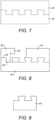
- this building member 46 can be cut from a single brick to provide two identical building members 46 as illustrated in Fig. 7 .
- Fig. 8 diagrammatically illustrates how a brick could be cut into three building members using quarter bond brickwork.
- the first being the building member 46
- a second being a short member 58 usable in forming a corner, with a dovetail profiled projection 60 at one end, and a dovetail profiled other end 62 to permit joining to a dovetail part shape projection 56 on another building member 46.
- a third building member 64 is provided which is equivalent to a half brick, i.e. a header. As can be seen this building member 64 extends for a little under a half of the length of the building member 46, to provide a space for the cementitious material to extend between adjacent building members.
- Fig. 9 shows this building member 64.
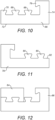
- Fig. 10 shows a further building member 66 usable as a corner or pistol with two full 68 and one part dovetail shape projection 70 on the rear of the front face 72, and a side face 74 with part of a dovetail shape projection 76 at the end thereof.
- Fig. 11 shows a similar corner member 78, but in this instance only two full dovetail shape projections 80 are provided such that a dovetail shape recess 82 extends to the right hand end as shown.
- Figs. 12 and 13 respectively show the corner building members 66, 78 connected to the half brick building member 64, with the orientation of the half brick building member 64 determined by which of the corner building members 66, 78 is used, depending on the orientation of the corner.
- Fig. 14 shows the stretcher building member 46 with two half brick building members 64 located thereon, illustrating the gap provided between the half brick building members 64 to enable cementitious material to locate therebetween in a conventional manner, relative to mortar used to join bricks together.
- Fig. 15 is a similar view to Fig. 1 but showing use of building members 78, 64, 46, 66 according to the invention. This illustrates the significantly increased surface area of the join between the cementitious material 14 and the building members 78, 64, 46, 66. As also can be seen the join between adjacent building members 78, 64, 46, 66 is provided between a part recess and a part projection which permits cementitious material 14 to extend further between the adjacent building members 78, 64, 46, 66 to provide a strong bond therebetween.
- the above described examples therefore provide a system for significantly enhanced bonding between the cementitious material and building members due to the increased surface area of the contact surface therebetween, and the mechanical keys.
- the use of the water jet cutting permits different profiles to be achieved with a greater surface area of contact faces between the cementitious material and the building members.
- the water jet cutting exposes the rough nature of the bricks providing a positive keying thereto of the cementitious material.
- the water jet cutting also removes any slurry from the surface of the brick in contrast to sawing.
- the rounded edges of the dovetail profile allows the cementitious material to flow around corners to fill voids, and to avoid trapped air which can occur with sharply angled corners. This cutting readily permits computer control for automatic cooperation whilst providing consistent profiles.
- the building members may gently diverge in one or both directions to provide increased bonding, with the rear side of the building members being cut at an inclination.
- the recesses and projections may have a different profile. Whilst the above invention is described in relation to bricks, other building members could be cut in this way.
Landscapes
- Engineering & Computer Science (AREA)
- Architecture (AREA)
- Civil Engineering (AREA)
- Structural Engineering (AREA)
- Ceramic Engineering (AREA)
- Chemical & Material Sciences (AREA)
- Mechanical Engineering (AREA)
- Electromagnetism (AREA)
- Physics & Mathematics (AREA)
- Life Sciences & Earth Sciences (AREA)
- Forests & Forestry (AREA)
- Dispersion Chemistry (AREA)
- Finishing Walls (AREA)
Claims (6)
- Verfahren zum Bilden eines Verkleidungspaneels, wobei das Verfahren Schneiden ursprünglicher gegenüberliegender Bauelemente umfasst, um gegenüberliegende Bauelemente zu bilden, die jeweils eine Vorderseite (32) und eine profilierte Rückseite (34) mit mindestens einem Paar mechanischer Tasten aufweisen, die mit bezogen auf die Vorderseite geneigten Kanten bereitgestellt sind, wobei das Paar eine Kante, die bezogen auf die Vorderseite in eine erste Richtung geneigt ist, und eine zweite Kante aufweist, die bezogen auf die Vorderseite in eine entgegengesetzte zweite Richtung geneigt ist, wobei das Paar mechanischer Tasten durch eine Aussparung (36, 38), die in der Draufsicht bezogen auf die Vorderseite ein Schwalbenschwanzprofil aufweist, und Vorsprünge auf der Rückseite des gegenüberliegenden Bauelements bereitgestellt ist; wobei das Verfahren ferner Anordnen der gegenüberliegenden Bauelemente in einem erforderlichen Muster in einer Form und Anordnen eines aushärtbaren Materials (22) auf der Rückseite der gegenüberliegenden Bauelemente umfasst, um nach dem Aushärten ein Verkleidungspaneel zu bilden, und wobei sich das aushärtbare Material in die Aussparung jedes gegenüberliegenden Bauelements erstreckt und in die Verbindungsstücke zwischen benachbarten Bauelementen des Verkleidungspaneels erstreckt,
und dadurch gekennzeichnet, dass das Schneiden durch einen Wasserstrahl durchgeführt wird und dass das ursprüngliche Bauelement ein geformter Lehmziegel ist. - Verfahren nach Anspruch 1, wobei das ursprüngliche Bauelement in zwei oder mehr Stücke geschnitten wird, um zwei oder mehr gegenüberliegende Bauelemente bereitzustellen, wobei entgegengesetzte Seiten des ursprünglichen Elements die jeweiligen Vorderseiten bereitstellen und die jeweiligen Rückseiten durch einen Schnitt durch das ursprüngliche Bauelement bereitgestellt werden.
- Verfahren nach Anspruch 1 oder 2, wobei das ursprüngliche Bauelement so geschnitten wird, dass zwei im Wesentlichen identische, gegenüberliegende Bauelemente bereitgestellt werden.
- Verfahren nach einem der Ansprüche 1 bis 3, wobei in dem Wasserstrahl ein festes Schleifmittel bereitgestellt wird.
- Verfahren nach einem der Ansprüche 1 bis 4, wobei das Schwalbenschwanzprofil abgerundete Kanten aufweist.
- Verfahren nach einem der Ansprüche 1 bis 5, wobei sich die oder jede Aussparung zwischen 25 % und 45 % der Dicke des gegenüberliegenden Bauelements erstreckt.
Applications Claiming Priority (2)
| Application Number | Priority Date | Filing Date | Title |
|---|---|---|---|
| GB1805184.7A GB2573501B (en) | 2018-03-29 | 2018-03-29 | Building member |
| PCT/GB2019/050939 WO2019186209A1 (en) | 2018-03-29 | 2019-03-29 | Facing building member |
Publications (3)
| Publication Number | Publication Date |
|---|---|
| EP3775428A1 EP3775428A1 (de) | 2021-02-17 |
| EP3775428B1 true EP3775428B1 (de) | 2025-01-01 |
| EP3775428C0 EP3775428C0 (de) | 2025-01-01 |
Family
ID=62142274
Family Applications (1)
| Application Number | Title | Priority Date | Filing Date |
|---|---|---|---|
| EP19718192.8A Active EP3775428B1 (de) | 2018-03-29 | 2019-03-29 | Verkleidungspaneel |
Country Status (4)
| Country | Link |
|---|---|
| US (2) | US20210363754A1 (de) |
| EP (1) | EP3775428B1 (de) |
| GB (1) | GB2573501B (de) |
| WO (1) | WO2019186209A1 (de) |
Families Citing this family (2)
| Publication number | Priority date | Publication date | Assignee | Title |
|---|---|---|---|---|
| GB2579769B (en) | 2018-10-25 | 2023-08-23 | Tectonic Facades Ltd | Cladding panel |
| US11352785B2 (en) * | 2020-01-31 | 2022-06-07 | B & B Flying Service, Inc. | Construction block units |
Citations (1)
| Publication number | Priority date | Publication date | Assignee | Title |
|---|---|---|---|---|
| US20100107534A1 (en) * | 2008-11-03 | 2010-05-06 | Scott System, Inc. | Modular layout form for embedding objects in a settable material |
Family Cites Families (49)
| Publication number | Priority date | Publication date | Assignee | Title |
|---|---|---|---|---|
| US707444A (en) * | 1901-10-10 | 1902-08-19 | J N Moses & Co | Masonry wall and bricks for same. |
| US802903A (en) * | 1904-10-04 | 1905-10-24 | Zacharias Anderson | Building-block and wall construction. |
| US1661037A (en) * | 1924-03-27 | 1928-02-28 | Goodrich Co B F | Paving tile |
| US1894371A (en) * | 1927-08-22 | 1933-01-17 | Prodorite S A | Acidproof tank |
| US2016382A (en) * | 1933-03-10 | 1935-10-08 | Owens Illinois Glass Co | Furnace tank construction |
| GB470858A (en) * | 1936-02-24 | 1937-08-24 | Eric Russell Harrap | Improvements relating to building blocks |
| GB1110114A (en) * | 1964-04-28 | 1968-04-18 | Proctor & Lavender Ltd | Improvements in, or relating to, panels |
| US3562988A (en) * | 1969-06-24 | 1971-02-16 | Lock Block Co Z | Building blocks, bricks, tile, panels and the like |
| US3562989A (en) * | 1969-06-24 | 1971-02-16 | Lock Block Co Z | Building blocks, bricks, tile, panels and the like |
| GB1301860A (de) * | 1969-12-23 | 1973-01-04 | ||
| US3817013A (en) * | 1971-08-26 | 1974-06-18 | D Selby | Insulated concrete block |
| DE2211747C3 (de) * | 1972-03-10 | 1979-03-22 | Buchtal Gmbh, 8472 Schwarzenfeld | Spaltplatte für Bekleidungen aus gebranntem keramischen Material |
| US3924056A (en) * | 1973-12-13 | 1975-12-02 | James T Locicero | Slotted masonry wall structure and metal stud therefor |
| FR2300185A1 (fr) * | 1975-02-07 | 1976-09-03 | Venturi Dominique | Dispositif d'element prefabrique pour la construction |
| US4003172A (en) * | 1975-09-30 | 1977-01-18 | Pawl Walter S | Peripherally grooved building blocks in a wall construction |
| DE2603827A1 (de) * | 1976-02-02 | 1977-08-04 | Berger Geb Braeunig Hildegard | Fassaden-verbundplatte |
| DE2632457A1 (de) * | 1976-07-19 | 1978-01-26 | Peter Paul Dichtl | Vorfabrizierte blendplatten fuer fassaden- und bauelementeverkleidung |
| JPS6026093A (ja) * | 1983-07-22 | 1985-02-08 | Hitachi Zosen Corp | 脱灰炭の製造方法 |
| US4551959A (en) * | 1983-10-19 | 1985-11-12 | Schmid Donald T | Building block |
| US4700527A (en) * | 1984-01-13 | 1987-10-20 | National Concrete Masonry Association | Concrete masonry block wall cladding construction system and blocks for same |
| ATE44299T1 (de) * | 1986-02-21 | 1989-07-15 | Rolf Scheiwiller | Bausatz zur erstellung von mauerwerken. |
| US4809470A (en) * | 1986-12-23 | 1989-03-07 | U.S. Brick, Inc. | Panel system and method |
| DE3740646A1 (de) * | 1987-12-01 | 1989-06-15 | Willi Ruckstuhl | Mauerstein aus beton zur erstellung einer trockenmauer |
| NO890861D0 (no) * | 1989-03-01 | 1989-03-01 | Mindor Sunde | Grunnmurselement. |
| US5281047A (en) * | 1992-05-28 | 1994-01-25 | Richard Skaug | Masonry landscaping modules and methods of landscaping |
| US5775046A (en) * | 1996-05-10 | 1998-07-07 | Massachusetts Institute Of Technology | Modular construction member |
| CA2206671C (en) * | 1996-06-21 | 2000-02-15 | Rolf C. Holzkaemper | Prefabricated composite building panel |
| US6041567A (en) * | 1996-11-05 | 2000-03-28 | Passeno; James Kenneth | Formliner for decorative wall |
| GB9708650D0 (en) * | 1997-04-30 | 1997-06-18 | Rudheath Construction Services | Building structures |
| CA2479258A1 (en) * | 2002-03-14 | 2003-09-18 | Wienerberger Bricks N.V. | Acoustic construction element |
| US6951086B2 (en) * | 2002-05-20 | 2005-10-04 | James Kenneth Passeno | Method and apparatus for making thin brick wall facing |
| AU2003901351A0 (en) * | 2003-03-24 | 2003-04-03 | Judi Collier | Composite building block having moisture barrier and insulation element |
| TW200513351A (en) * | 2003-07-17 | 2005-04-16 | Availvs Corp | High pressure water jet surface cutting device and cutting method |
| US7410328B2 (en) * | 2006-06-14 | 2008-08-12 | Transpavé Inc. | Concrete block system |
| ITMI20062056A1 (it) * | 2006-10-25 | 2008-04-26 | Techlever S P A | Parete ventilata comprendente elementi di supporto e relativa struttura di rivestimento |
| CA2686077A1 (en) * | 2007-06-21 | 2008-12-24 | Keystone Retaining Wall Systems, Inc. | Veneers for walls, retaining walls, retaining wall blocks, and the like |
| CH707224B1 (de) * | 2007-07-23 | 2014-05-30 | Serge Lunin | Flächiges Bauelement. |
| WO2009051463A1 (es) * | 2007-10-17 | 2009-04-23 | Silvia Rosa Zambrano Hornedo | Sillares ensamblables para el armado de módulos de construcción |
| US20100107531A1 (en) * | 2008-11-06 | 2010-05-06 | Garrick Hunsaker | Thin brick matrix panel and related methods and systems |
| GB0922112D0 (en) * | 2009-05-22 | 2010-02-03 | Oldcastle Apg Inc | Building block and cladding system |
| CN201762932U (zh) * | 2010-09-09 | 2011-03-16 | 南安市贝斯泰石业有限公司 | 一种半宝石石材大板 |
| US8708608B2 (en) * | 2010-09-15 | 2014-04-29 | Allan Block Llc | Stackable segmental retaining wall block |
| EP2683887B1 (de) * | 2011-03-09 | 2019-09-11 | Quadrosera Corporation | Klammern für ein mauersystem mit dünnen backsteinen |
| US9032684B2 (en) * | 2011-03-09 | 2015-05-19 | Quadrosera Corporation | Clips for thin brick wall system |
| US9260864B2 (en) * | 2012-04-03 | 2016-02-16 | James Hardie Technology Limited | Integrated fiber cement and foam as insulated cladding with enhancements |
| GB201405793D0 (en) * | 2014-03-31 | 2014-05-14 | Keystone Lintels Ltd | A covering for a building component |
| USD911556S1 (en) * | 2019-03-21 | 2021-02-23 | Brickworks Building Products Pty Ltd | Brick |
| USD912279S1 (en) * | 2019-03-21 | 2021-03-02 | Brickworks Building Products Pty Ltd | Brick |
| USD911557S1 (en) * | 2019-08-06 | 2021-02-23 | Brickworks Building Products Pty Ltd | Brick |
-
2018
- 2018-03-29 GB GB1805184.7A patent/GB2573501B/en active Active
-
2019
- 2019-03-29 WO PCT/GB2019/050939 patent/WO2019186209A1/en not_active Ceased
- 2019-03-29 US US17/043,513 patent/US20210363754A1/en not_active Abandoned
- 2019-03-29 EP EP19718192.8A patent/EP3775428B1/de active Active
-
2023
- 2023-05-26 US US18/202,843 patent/US20230295925A1/en not_active Abandoned
Patent Citations (1)
| Publication number | Priority date | Publication date | Assignee | Title |
|---|---|---|---|---|
| US20100107534A1 (en) * | 2008-11-03 | 2010-05-06 | Scott System, Inc. | Modular layout form for embedding objects in a settable material |
Also Published As
| Publication number | Publication date |
|---|---|
| US20210363754A1 (en) | 2021-11-25 |
| GB201805184D0 (en) | 2018-05-16 |
| EP3775428A1 (de) | 2021-02-17 |
| GB2573501B (en) | 2020-09-16 |
| US20230295925A1 (en) | 2023-09-21 |
| WO2019186209A1 (en) | 2019-10-03 |
| EP3775428C0 (de) | 2025-01-01 |
| GB2573501A (en) | 2019-11-13 |
Similar Documents
| Publication | Publication Date | Title |
|---|---|---|
| US6777063B2 (en) | Composite backerboard for bullnose support | |
| US20230295925A1 (en) | Facing building member | |
| US20220307272A1 (en) | Fiber enforced thin brick sheet and process | |
| CN106460393B (zh) | 具有通用连接系统的地板 | |
| US9027302B2 (en) | Wall panel | |
| US9297160B2 (en) | Composite panel made from cementitious mortar with properties of transparency | |
| CN1074264A (zh) | 镶面的建筑板 | |
| CN105804353A (zh) | 一种可快速安装的建筑表面装饰材料 | |
| CN103790334A (zh) | 复合拼接地砖及其铺贴工艺 | |
| GB2291079A (en) | Insulated building blocks | |
| CN210685267U (zh) | 一种拼接瓷砖 | |
| US4952445A (en) | Marble tile trim | |
| US11959285B2 (en) | Cladding panel | |
| WO1990012932A1 (en) | Corner joint for building units of stone | |
| US5620278A (en) | Tile | |
| JPH10331394A (ja) | Pc工法用天然石材タイル及びコンクリートパネル | |
| JP2653624B2 (ja) | 外壁横張用中空押出成形板 | |
| JP2001049830A (ja) | 目 地 | |
| KR20030072274A (ko) | 건축 내, 외장재용 석재 타일 및 이의 제조방법 | |
| KR100300781B1 (ko) | 석재판넬 | |
| WO2001066874A3 (en) | Stone surfacing for counters, walls, and floors | |
| FR2300185A1 (fr) | Dispositif d'element prefabrique pour la construction | |
| KR200300628Y1 (ko) | 건축용 인조석 타일 | |
| TWM583468U (zh) | 輕質水泥板 | |
| GB2620548A (en) | Stone veneered building block |
Legal Events
| Date | Code | Title | Description |
|---|---|---|---|
| STAA | Information on the status of an ep patent application or granted ep patent |
Free format text: STATUS: UNKNOWN |
|
| STAA | Information on the status of an ep patent application or granted ep patent |
Free format text: STATUS: THE INTERNATIONAL PUBLICATION HAS BEEN MADE |
|
| PUAI | Public reference made under article 153(3) epc to a published international application that has entered the european phase |
Free format text: ORIGINAL CODE: 0009012 |
|
| STAA | Information on the status of an ep patent application or granted ep patent |
Free format text: STATUS: REQUEST FOR EXAMINATION WAS MADE |
|
| 17P | Request for examination filed |
Effective date: 20201029 |
|
| AK | Designated contracting states |
Kind code of ref document: A1 Designated state(s): AL AT BE BG CH CY CZ DE DK EE ES FI FR GB GR HR HU IE IS IT LI LT LU LV MC MK MT NL NO PL PT RO RS SE SI SK SM TR |
|
| AX | Request for extension of the european patent |
Extension state: BA ME |
|
| DAV | Request for validation of the european patent (deleted) | ||
| DAX | Request for extension of the european patent (deleted) | ||
| STAA | Information on the status of an ep patent application or granted ep patent |
Free format text: STATUS: EXAMINATION IS IN PROGRESS |
|
| 17Q | First examination report despatched |
Effective date: 20221219 |
|
| RIN1 | Information on inventor provided before grant (corrected) |
Inventor name: THORP, HARVEY RICHARD |
|
| GRAP | Despatch of communication of intention to grant a patent |
Free format text: ORIGINAL CODE: EPIDOSNIGR1 |
|
| STAA | Information on the status of an ep patent application or granted ep patent |
Free format text: STATUS: GRANT OF PATENT IS INTENDED |
|
| INTG | Intention to grant announced |
Effective date: 20240311 |
|
| GRAJ | Information related to disapproval of communication of intention to grant by the applicant or resumption of examination proceedings by the epo deleted |
Free format text: ORIGINAL CODE: EPIDOSDIGR1 |
|
| STAA | Information on the status of an ep patent application or granted ep patent |
Free format text: STATUS: EXAMINATION IS IN PROGRESS |
|
| GRAP | Despatch of communication of intention to grant a patent |
Free format text: ORIGINAL CODE: EPIDOSNIGR1 |
|
| STAA | Information on the status of an ep patent application or granted ep patent |
Free format text: STATUS: GRANT OF PATENT IS INTENDED |
|
| INTC | Intention to grant announced (deleted) | ||
| INTG | Intention to grant announced |
Effective date: 20240723 |
|
| GRAS | Grant fee paid |
Free format text: ORIGINAL CODE: EPIDOSNIGR3 |
|
| GRAA | (expected) grant |
Free format text: ORIGINAL CODE: 0009210 |
|
| STAA | Information on the status of an ep patent application or granted ep patent |
Free format text: STATUS: THE PATENT HAS BEEN GRANTED |
|
| AK | Designated contracting states |
Kind code of ref document: B1 Designated state(s): AL AT BE BG CH CY CZ DE DK EE ES FI FR GB GR HR HU IE IS IT LI LT LU LV MC MK MT NL NO PL PT RO RS SE SI SK SM TR |
|
| REG | Reference to a national code |
Ref country code: GB Ref legal event code: FG4D |
|
| REG | Reference to a national code |
Ref country code: CH Ref legal event code: EP |
|
| REG | Reference to a national code |
Ref country code: DE Ref legal event code: R096 Ref document number: 602019064235 Country of ref document: DE |
|
| REG | Reference to a national code |
Ref country code: IE Ref legal event code: FG4D |
|
| U01 | Request for unitary effect filed |
Effective date: 20250117 |
|
| U07 | Unitary effect registered |
Designated state(s): AT BE BG DE DK EE FI FR IT LT LU LV MT NL PT RO SE SI Effective date: 20250123 |
|
| U20 | Renewal fee for the european patent with unitary effect paid |
Year of fee payment: 7 Effective date: 20250304 |
|
| PGFP | Annual fee paid to national office [announced via postgrant information from national office to epo] |
Ref country code: IE Payment date: 20250226 Year of fee payment: 7 |
|
| PGFP | Annual fee paid to national office [announced via postgrant information from national office to epo] |
Ref country code: GB Payment date: 20250304 Year of fee payment: 7 |
|
| PG25 | Lapsed in a contracting state [announced via postgrant information from national office to epo] |
Ref country code: PL Free format text: LAPSE BECAUSE OF FAILURE TO SUBMIT A TRANSLATION OF THE DESCRIPTION OR TO PAY THE FEE WITHIN THE PRESCRIBED TIME-LIMIT Effective date: 20250101 |
|
| PG25 | Lapsed in a contracting state [announced via postgrant information from national office to epo] |
Ref country code: ES Free format text: LAPSE BECAUSE OF FAILURE TO SUBMIT A TRANSLATION OF THE DESCRIPTION OR TO PAY THE FEE WITHIN THE PRESCRIBED TIME-LIMIT Effective date: 20250101 |
|
| PG25 | Lapsed in a contracting state [announced via postgrant information from national office to epo] |
Ref country code: NO Free format text: LAPSE BECAUSE OF FAILURE TO SUBMIT A TRANSLATION OF THE DESCRIPTION OR TO PAY THE FEE WITHIN THE PRESCRIBED TIME-LIMIT Effective date: 20250401 Ref country code: IS Free format text: LAPSE BECAUSE OF FAILURE TO SUBMIT A TRANSLATION OF THE DESCRIPTION OR TO PAY THE FEE WITHIN THE PRESCRIBED TIME-LIMIT Effective date: 20250501 |
|
| PG25 | Lapsed in a contracting state [announced via postgrant information from national office to epo] |
Ref country code: HR Free format text: LAPSE BECAUSE OF FAILURE TO SUBMIT A TRANSLATION OF THE DESCRIPTION OR TO PAY THE FEE WITHIN THE PRESCRIBED TIME-LIMIT Effective date: 20250101 |
|
| PG25 | Lapsed in a contracting state [announced via postgrant information from national office to epo] |
Ref country code: GR Free format text: LAPSE BECAUSE OF FAILURE TO SUBMIT A TRANSLATION OF THE DESCRIPTION OR TO PAY THE FEE WITHIN THE PRESCRIBED TIME-LIMIT Effective date: 20250402 |
|
| PG25 | Lapsed in a contracting state [announced via postgrant information from national office to epo] |
Ref country code: CZ Free format text: LAPSE BECAUSE OF FAILURE TO SUBMIT A TRANSLATION OF THE DESCRIPTION OR TO PAY THE FEE WITHIN THE PRESCRIBED TIME-LIMIT Effective date: 20250101 |
|
| PG25 | Lapsed in a contracting state [announced via postgrant information from national office to epo] |
Ref country code: SM Free format text: LAPSE BECAUSE OF FAILURE TO SUBMIT A TRANSLATION OF THE DESCRIPTION OR TO PAY THE FEE WITHIN THE PRESCRIBED TIME-LIMIT Effective date: 20250101 |
|
| PG25 | Lapsed in a contracting state [announced via postgrant information from national office to epo] |
Ref country code: MC Free format text: LAPSE BECAUSE OF FAILURE TO SUBMIT A TRANSLATION OF THE DESCRIPTION OR TO PAY THE FEE WITHIN THE PRESCRIBED TIME-LIMIT Effective date: 20250101 |
|
| REG | Reference to a national code |
Ref country code: CH Ref legal event code: H13 Free format text: ST27 STATUS EVENT CODE: U-0-0-H10-H13 (AS PROVIDED BY THE NATIONAL OFFICE) Effective date: 20251023 |
|
| PG25 | Lapsed in a contracting state [announced via postgrant information from national office to epo] |
Ref country code: SK Free format text: LAPSE BECAUSE OF FAILURE TO SUBMIT A TRANSLATION OF THE DESCRIPTION OR TO PAY THE FEE WITHIN THE PRESCRIBED TIME-LIMIT Effective date: 20250101 |
|
| PLBE | No opposition filed within time limit |
Free format text: ORIGINAL CODE: 0009261 |
|
| STAA | Information on the status of an ep patent application or granted ep patent |
Free format text: STATUS: NO OPPOSITION FILED WITHIN TIME LIMIT |